RD600T1 使用说明书
RD600T变压器保护使用说明书资料
RDRD600T型微机变压器保护测控装置2006年6月使用说明书V1.01、概述装置适用于35KV及以下电压等级厂用、站用变压器的保护、测量及控制。
既可以分散在开关柜就地安装,也可以集中组屏安装。
完善的设计保证了装置可以在恶劣环境下长期、可靠地运行。
现场总线技术和标准通信规约的使用,保证了自动化系统通讯的可靠性、快速性和易用性。
装置具有独立的操作回路和防跳继电器。
2、主要功能2.1 保护功能配置:高压侧速断保护高压侧定时限过流保护高压侧反时限过流保护⏹一次曲线/二次曲线可选高压侧过负荷保护⏹告警/跳闸可以选择高压侧定时限不平衡电流保护高压侧反时限不平衡电流保护⏹一次曲线/二次曲线可选高压侧零序过流保护⏹零序电压闭锁低电压保护低压侧定时限零序电流保护低压侧反时限零序电流保护⏹一次曲线/二次曲线可选轻瓦斯告警重瓦斯跳闸高温告警超温跳闸PT断线检测2.2 数据采集功能遥测⏹实时采集三相电流、三相电压、零序电流、零序电压⏹正负有功功率、无功功率、频率、功率因数遥信⏹15路遥信量(控制回路4路,外部11路)遥控⏹两路遥控继电器,远方控制断路器合、分电度采集⏹2路电度脉冲输入2.3 事件记录保护事件告警事件遥信变位事件操作记录事件2.4 控制功能就地/远方分、合闸控制122.5 操作箱功能跳合位指示可靠的自保持及防跳设计 跳、合闸电流自适应 控制回路断线告警2.6 通讯功能高速光电隔离CAN 总线 高速光电隔离RS485总线2.7 故障记录及查询功能 3、保护配置及工作原理3.1 速断保护本装置提供高压侧电流速断保护。
任一相保护电流大于速断整定值并达到整定延时保护动作。
3.2 定时限过流保护本装置提供高压侧定时限过流保护。
任一相保护电流大于过流整定值并达到整定延时保护动作。
3.3 反时限过流保护本装置提供高压侧反时限过电流保护。
提供两种曲线的反时限特性,反时限曲线可以选择。
一次反时限曲线: 1)(-=fs fsI I T t二次反时限曲线:1)(2-=fs fs I I T t式中: Tfs -- 时间常数; Ifs – 反时限启动电流;I – 高压侧实际运行电流 3.4 过负荷保护本装置提供高压侧过负荷保护。
TR600 使用说明书
TR600数字式应变电阻传感器变送器使用说明书LONGTEC 珠海市长陆工业自动控制系统有限公司用前须知:u初次使用前,请详细阅读本说明书,现场使用许多疑难问题,在本说明书中将找到答案。
u使用前,请检查称重系统其他部件是否匹配。
u使用本仪表,注意防晒、防雨水、防撞击。
u使用本仪表,请尽可能配备常用安装、检修工具:小型一字螺丝刀,数字式万用表,称重传感器模拟器(mV信号发生器)。
目录用前须知: (1)1概述 (5)1-1简介 (5)1-2有关术语 (5)1-3特点 (5)2技术参数 (6)2-1一般参数 (6)2-2数字部分 (6)2-3模拟部分 (6)3安装 (7)3-1安装注意事项 (7)3-2变送器输入灵敏度 (7)3-3传感器与变送器之连接法 (8)3-4变送器最长可联接的称重信号电缆长度表 (8)3-5称重传感器接线方式 (8)3-6安装尺寸图(单位:MM) (8)4显示面板及按键说明 (9)4-1前面板及打开保护盖示意图 (9)4-2保护盖 (9)4-3接线端子说明 (10)4-4数码显示说明 (10)4-5在称重状态下各功能键的说明 (10)4-6波特率选择说明 (10)4-7ID地址选择说明 (10)5功能设置 (11)5-1参数设定 (11)5-1-1“FUNC”进入设定 (11)5-1-2“F10”零位跟踪时间 (12)5-1-3“F20”动态检测范围 (12)5-1-4“F30”RS232/485通讯输出速率 (12)5-1-5“F40”小数点选择 (13)5-1-6“F50”分度间距 (13)5-1-7“F6 0”最大量程 (13)5-1-8“F70”数字滤波 (14)5-2经由RS232/RS485接口设定功能(配RS232或RS485有此功能) (15)5-2-1零位跟踪范围 (15)5-2-2动态检测范围 (15)5-2-3RS232/RS485通讯输出速率 (15)5-2-4小数点 (15)5-2-5分度间距 (16)5-2-6最大量程 (16)5-2-7数字滤波 (16)6.仪表标定 (16)6-1标定的意义 (16)6-2操作 (17)6-2-1零位标定 (18)6-2-2秤量间距标定 (18)6-2-3标定错误提示 (19)6-3经由RS232/RS485接口标定(配RS232或RS485有此功能) (20)6-3-1 TR600可经由RS232/RS485接口直接调校 (20)7.称重定值比较量设置按键操作: (21)7-1设置参数步骤 (21)7-2经由RS232/RS485设定比较值(配RS232或RS485有此功能) (23)8.通讯参数的设定 (23)8-1通讯格式说明 (23)8-2波特率的设定 (25)8-3通讯ID地址的设定 (25)9.输入/输出 (25)9-1控制输入 (25)9-1-1输入接口(内置) (25)9-1-2输入接口与外接开关的联接 (26)9-1-3输入接口与PLC的联接......................................................................................错误!未定义书签。
佳能600D使用说明书(共2篇)

篇一:佳能eos600d相机最基本使用说明1,一般使用1.1基本模式a+模式用于一般拍摄禁止闪光模式用于博物馆等场景ca模式1.2佳能还提供了几种常用配置。
人像模式景色模式微距模式运动模式夜间模式1.3常用按钮作用1.3.1镜头上:af/mf,是否允许镜头自动对焦【半按拍摄按钮时,镜头自动对焦功能】。
af允许。
mf 不允许。
stabilizer on/of,防抖功能。
在手持相机时,能够减少手抖对照片的影响。
·手持拍摄且曝光时间超过1/100秒开着。
·上架子或者强光下拍摄时关掉更好。
·拍摄视频时最好关掉,不关闭稳定器会有持续的噪音并且很费电。
1.3.2机身:,2,快门优先和光圈优先的区别照片的好坏与曝光量有关,也就是说应该通多少的光线使ccd能够得到清晰的图像。
曝光量与通光时间(快门速度决定),通光面积(光圈大小决定)有关。
那么,为了得到正确的曝光量,就需要正确的快门与光圈的组合。
快门快时,光圈就要大些;快门慢时,光圈就要小些。
快门优先【佳能的tv模式】是指由机器自动测光系统计算出曝光量的值,然后根据你选定的快门速度自动决定用多大的光圈。
光圈优先【佳能的av模式】是指由机器自动测光系统计算出曝光量的值,然后根据你选定的光圈大小自动决定用多少的快门。
手动模式【佳能的m模式】是指你自己指定光圈的大小与快门的速度。
快门优先用于你对快门有要求的时候,如你拍摄高速运动的物体,快门必须要快一些,所以你控制快门,由相机控制光圈。
需要注意的是,光圈的可调范围小于快门,所以用快门优先时,如果你把快门调得太快或太慢,相机是没有办法正确曝光的。
速度控制:在同一环境下,光圈和快门是相辅相成的,光圈越大,进入的光线就越多,所需的快门时间就越短,反之,光圈越小,快门速度就越慢,因而可以通过光圈来调节快门。
比如在光线较暗的场合,用光圈优先设定大光圈,相机会选择较高的快门速度,从而保证手持相机时的稳定性。
TR600 使用说明书

TR600数字式应变电阻传感器变送器使用说明书LONGTEC 珠海市长陆工业自动控制系统有限公司用前须知:u初次使用前,请详细阅读本说明书,现场使用许多疑难问题,在本说明书中将找到答案。
u使用前,请检查称重系统其他部件是否匹配。
u使用本仪表,注意防晒、防雨水、防撞击。
u使用本仪表,请尽可能配备常用安装、检修工具:小型一字螺丝刀,数字式万用表,称重传感器模拟器(mV信号发生器)。
目录用前须知: (1)1概述 (5)1-1简介 (5)1-2有关术语 (5)1-3特点 (5)2技术参数 (6)2-1一般参数 (6)2-2数字部分 (6)2-3模拟部分 (6)3安装 (7)3-1安装注意事项 (7)3-2变送器输入灵敏度 (7)3-3传感器与变送器之连接法 (8)3-4变送器最长可联接的称重信号电缆长度表 (8)3-5称重传感器接线方式 (8)3-6安装尺寸图(单位:MM) (8)4显示面板及按键说明 (9)4-1前面板及打开保护盖示意图 (9)4-2保护盖 (9)4-3接线端子说明 (10)4-4数码显示说明 (10)4-5在称重状态下各功能键的说明 (10)4-6波特率选择说明 (10)4-7ID地址选择说明 (10)5功能设置 (11)5-1参数设定 (11)5-1-1“FUNC”进入设定 (11)5-1-2“F10”零位跟踪时间 (12)5-1-3“F20”动态检测范围 (12)5-1-4“F30”RS232/485通讯输出速率 (12)5-1-5“F40”小数点选择 (13)5-1-6“F50”分度间距 (13)5-1-7“F6 0”最大量程 (13)5-1-8“F70”数字滤波 (14)5-2经由RS232/RS485接口设定功能(配RS232或RS485有此功能) (15)5-2-1零位跟踪范围 (15)5-2-2动态检测范围 (15)5-2-3RS232/RS485通讯输出速率 (15)5-2-4小数点 (15)5-2-5分度间距 (16)5-2-6最大量程 (16)5-2-7数字滤波 (16)6.仪表标定 (16)6-1标定的意义 (16)6-2操作 (17)6-2-1零位标定 (18)6-2-2秤量间距标定 (18)6-2-3标定错误提示 (19)6-3经由RS232/RS485接口标定(配RS232或RS485有此功能) (20)6-3-1 TR600可经由RS232/RS485接口直接调校 (20)7.称重定值比较量设置按键操作: (21)7-1设置参数步骤 (21)7-2经由RS232/RS485设定比较值(配RS232或RS485有此功能) (23)8.通讯参数的设定 (23)8-1通讯格式说明 (23)8-2波特率的设定 (25)8-3通讯ID地址的设定 (25)9.输入/输出 (25)9-1控制输入 (25)9-1-1输入接口(内置) (25)9-1-2输入接口与外接开关的联接 (26)9-1-3输入接口与PLC的联接......................................................................................错误!未定义书签。
600系列说明书

600系列三相电力仪表(版本号:4.00)使用说明书(使用前请详细阅读此说明书)目录1、简述 (1)1.1 600的功能 (1)1.2 600功能描述 (1)1.3 600的特点 (1)2、安装、接线与配置 (2)2.1 尺寸与安装 (2)2.2 接线与配置 (3)3、界面显示说明 (5)3.1 显示模式下按键功能示意图 (5)3.2 编程模式下参数查询及修改按键功能示意图 (5)3.3 显示模式下功能显示灯指示说明 (6)4、操作说明 (6)4.1 循环显示说明 (6)4.2 键盘编程说明 (6)4.3 功能设置 (6)5、运输与贮藏 (7)6、保修期限及订货说明 (7)附表:常见故障排除 (8)1、简述1.1 600系列的功能600系列三相电力仪表是用于低压电力系统的智能化装置,该系列产品包括电流表、电压表、有功功率表、无功功率表、功率因数表、电度表等适合用户不同应用需求的仪表产品,该系列仪表可以完全替各种代指针式电力仪表,且精确度更好、性能更加稳定。
600系列三相电力仪表具有选配4路开关量输入、2路脉冲输出、RS485通讯接口,通讯协议为MODBUS通讯协议或其它指定通讯协议。
1.2 600系列功能描述1.2.2 通讯功能(扩展功能)600系列产品均可选配RS485通讯接口,通讯协议为MODBUS通讯协议或其它指定通讯协议。
可通过通讯口,可查询全部的测量监控信息。
面板带有带有LED指示灯,用于通讯收/发指示。
1.2.3 1~4路开关量输入功能(扩展功能)600系列产品均可选配1~4路开关量输入,为无源节点输入。
可在测量显示区查看开关量的状态。
1.2.4 模拟量输出功能(扩展功能)600系列部分产品可选配1~2路DC4~20mA,通过编程设置可将模拟量(DC 4-20mA)输出设置为与某一被测参数(定货时需指定)成比例的输出。
模拟量输出的最大负载为300Ω,可选择项为三相电流表的IA、IB、IC,三相电压表的UA、UB、UC。
德能 D-T1 操作说明书

D-T1CD RECEIVER SYSTEM 操作说明书附件5安装电池6遥控器的操作范围6特点7部件名称与功能8前面板8后面板11遥控器13连接方法连接扬声器17连接扬声器电缆17连接扬声器18连接模拟设备19连接数字设备19连接FM/AM天线20连接电源线22播放基本操作24开启电源24切换电源至待机24选择输入源25调节主音量25暂时关闭声音(静音)25播放CD26播放CD26以特定顺序播放曲目(编程播放)27播放DATA CD28播放文件29收听FM/AM广播30收听FM/AM广播30预设FM/AM电台31收听预设电台31在主机上设置预设频道和更改接收频率32在蓝牙设备上收听音乐33在蓝牙设备上收听音乐34与其他蓝牙设备配对35断开蓝牙连接36设置蓝牙待机模式36从蓝牙设备重新连接至本机37播放数字输入38播放模拟输入39便捷功能40调节音调41切换显示屏亮度42设置设置时钟、定时器播放和睡眠定时器44设定当前时间44持续显示时钟45设置定时器播放46设置定时器播放模式47睡眠定时器功能47设置自动待机模式48开启自动待机模式48关闭自动待机模式48提示提示50故障诊断51恢复出厂设置59保修和修理60附录播放DATA CD61 DIGITAL IN62播放蓝牙设备62关于光碟63最新功能记忆65术语解释66商标信息67规格68索引72感谢您选购本款Denon产品。
为确保正确操作,使用该产品前请仔细阅读操作说明书。
阅读之后,请务必妥善保管以备将来参考。
附件请检查并确认本产品附带下列部件。
安装电池12按照指示将两节电池正确插入电池匣内。
3装上后盖。
注0为防止损坏电池或电池漏液 :0请勿将新旧电池混合使用。
0请勿使用两种不同类型的电池。
0如果打算长时间不使用遥控器,请取出遥控器中的电池。
0如果电池漏液,须仔细地擦去电池匣内的漏液,然后装入新电池。
遥控器的操作范围操作遥控器时,请将其指向遥控感应窗。
RD8000 管线仪使用参考手册3.0

infeng® 英凤科技
目录 1
RD8000 管线仪用户使用参考手册
3.13 音讯……………………………………………………………………………………13 3.14 背光……………………………………………………………………………………13 3.15 发射机输出功率………………………………………………………………………13 3.16 增压功能………………………………………………………………………………14 3.17FREQ……………………………………………………………………………………15 3.18 导线信号夹钳图标……………………………………………………………………15
7.3 追踪………………………………………………………………………………………27 7.4 精确定位…………………………………………………………………………………27 7.5 扫描和搜索………………………………………………………………………………28
第 8 节 深度和电流读数……………………………………………………………………31
第 6 节 iLOCM™…………………………………………………………………………………22
百得燃烧器说明书
t3
<t2>
<t3>
4
t2 <t2> 1
t4 LGB 21... LGB 22...
B-B’ C C-D
<t4>
IIII tw t10 tw t11
(LGB21) (LGB22)
(LGB22)
P LGB22
t2
t1 t3 t2
t1 t3(t12)
(LGB21) (LGB22)
(LGB22)
1 )
2
(LGB21)
SPARKGAS 20 SPARKGAS 20W SPARKGAS 30 SPARKGAS 30W SPARKGAS 35 SPARKGAS 35W
/ OVERAL DIMENSIONS
A A1 A2 B B1 B2 B3 C
D
EF G
L
MN
R/P 490 245 245 575 275 300 170 765 120 280 126 95 3/4 105 - - M8 130
= 1mbar =1kg/cm2
L.P.G. L.P.G.
= 30mbar=0.03kg/cm2 =
BT 8721/2 REV. 21/03/90
1)
1)
2)
2)
1)
1)
2)
2)
3)
3)
1)
1)
18
Rev.
-
-
AD-PE(
-)
-
SS
PN 40(
40 bar)
1)
2)
3)
4)
18 bar
19
BERGER STA 5 B0. 36/8 2/N 36L
600系列报警主机说明书
600系列主机基本功能一、型号说明:600系列主机有以下几个型号:TTX6084、TTX6164、TTX6224、TTX6324,分别为8进4出、16进4出、24进4出,键盘为TTX600VJ (一主机可带4键盘)二、功能说明1、8、16、24、32路视频输入可选,标准为4路视频输出2、C 型控制方式(同轴视控)或D 型控制方式(RS485方式)3、带有视频环通输出4、128路报警输入,带报警联动功能,1个报警继电器输出(50V A )600系列键盘操作说明变速摇杆键盘,支持变速操作一 .键盘基本操作选择一个摄象机、视频序列和监视器1. nn + [CAMERA]:选择nn 号摄象机在当前监视器上进行操作(nn=1—32);2. nn + [SEQUENCE RECALL];选择一个预先编程好的视频序列(nn=1—4);3. 选择监视器:扭动钥匙,键盘显示PR ,再按[CAMERA],可改变监视器号,根据需要选择几号监视器;(或者是按住[CAMERA]保持5S ,然后再按[CAMERA],可改变监视器号,根据需要选择几号监视器)选择预置位4. nn + [PRESET RECALL]:调用一个预先编程好的预置位;(nn=1—16)5. [PRESET RECALL]:瞬时功能6. 操作杆: 控制云台水平、垂直方向功能;7.[LENS FUNCTIONS ]: 光圈开、关,聚焦远、近,视角大、小;8.[HOME]: 使云台回到初始点,即预置位1;[WASH]: 开启喷水器,[AUX2]:使用直流云台时,会使其速度加倍。
开关控制功能键[LENS SLOW]、[AUTO IRIS]、[LAMPS]、[CAMARA ON/OFF]、[WIPE]、[AUX1]分别为镜头慢速,自动光圈,灯光,摄象机开关,雨刮器,辅助功能键(以上各功能要求设备具有相应的功能才能实现)。
[ALL ON]、[ALL OFF]全开和全关功能,例如:[ALL ON] [WIPE]就是将所有的雨刷器都打开。
多回转电动装置使用说明书
1.概述多回转阀门电动装置,简称为Z型电装,是阀门实现开启、关闭或调节控制的驱动设备。
Z型电装适用于闸阀、截止阀、隔膜阀、柱塞阀、节流阀、水闸门等。
可用于明杆阀,也可用于暗杆阀。
本系列电装具有功能全、性能可靠、控制系统先进、体积小、重量轻、使用维护方便等特点。
可对阀门实行远控、集控和自动控制。
广泛用于电力、冶金、石油、化工、造纸、污水处理等行业。
本产品的性能符合JB/T8528-1997《普通型阀门电动装置技术条件》的规定。
隔爆型的性能符合GB3836.1-2000《爆炸性气体环境用电气设备第1部分:通用要求》,GB3836.2-2000《爆炸性气体环境用电气设备第2部分:隔爆型“d”》及JB/T8529-1997《隔爆型阀门电动装置技术条件》的规定。
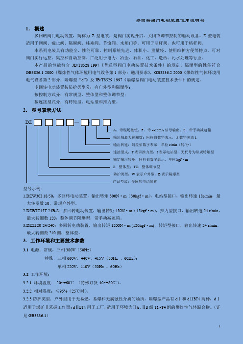
多回转电动装置按防护类型分:有户外型和隔爆型;按控制方式分:有常规型、整体型和整体调节型;按连接型式分:有转矩型、电站型和推力型。
2.型号表示方法DZ —/A:带现场按钮;F:带4-20mA信号输出;S:带手动减速箱输出轴最大转圈数:阿拉伯数字表示,无数字见表1输出转速:阿拉伯数字表示,单位r/min(转/分)连接型式:T表示推力型,I表示电站型,无代号为常规转矩型额定输出转矩:阿拉伯数字表示,单位kgf·mZ:整体型;TZ:整体调节型防护类型:W表示户外型;B表示隔爆型产品型式:多回转电动装置型号示例:1.DZW30I-18/50:多回转电动装置,输出转矩300N·m(30kgf·m),电站型接口,输出转速18r/min,最大转圈数50,常规户外型。
2.DZBTZ45T-24B/S:多回转电动装置,输出转矩450N·m(45kgf·m),推力型接口,输出转速24 r/min,最大转圈数120,整体调节隔爆型,带手动减速箱。
3.DZZ120-24/240:多回转电动装置,输出转矩1200N·m (120kgf·m),转矩型接口,输出转速24 r/min,最大转圈数240圈,整体型。
RD600F 使用说明书

6
KZ1(控制字 1)各位定义如下:(1-投入;0-退出)
D7 D6 D5 D4 D3 D2 D1 D0
D0 母充保护投退 D1 速断保护投退 D2 速断低压闭锁投退 D3 速断方向闭锁投退
D4 限时速断投退 D5 限时速断低压闭锁投退 D6 限时速断方向闭锁投退 D7 限时速断后加速投退
KZ2(控制字 2)各位定义如下:(1-投入;0-退出)
D0 检同期重合投退 D1 PT 断线告警投退 D2 PT 断线闭锁投退 D3 备用
D4 备用 D5 备用 D6 备用 D7 备用
7
5、RD600F 型微机线路保护测控装置端子图
8
编号
名称
A01 屏蔽地
A02
A03
装 AC/DC+ 置
A04
电
A05
AC/DC-
源
A06
A07
A08 +24V
电
A09
本装置提供母线充电保护。在检测到手动合闸 3 秒内,任一相保护电流大于整定值并达到整
2
定延时后保护即动作。手合 3 秒后,母充保护自动退出运行。 3.2 三段过流保护(速断、限时速断、定时限过流)
本装置配置了三段过流保护,可分别选择方向元件和复合电压元件闭锁。二、三段可选择是
否投入后加速功能,后加速时间可以单独设定。
源
A10 -24V
输 出
A11
A12
A13 电源消失 信
A14
号
A15 备用出口1
A16
保
A17 备用出口2 A18
护 出
口
A19 备用出口3
A20
编号
名称
B01 遥控正电源入
RD6000中文说明书
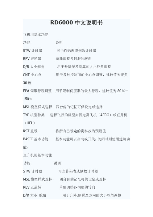
RD6000中文说明书飞机用基本功能功能说明STW计时器可当作码表或倒数计时器REV正逆器单独调整各伺服的转向D/R大小舵角用于升降舵及副翼的大小舵角调整CNT中心点用于各种控制面的中心点调整,建议值为正负30度EPA伺服行程调整用于限制伺服器的最大行程,建议值为80%-150%MSL模型样式选择四台份的记忆可供设定或选择TYP机型种类选择飞行的机型如固定翼飞机(AERO)或直升机(HEL)RST重设将所有已设定的资料改为预设值BASIC基本功能基本功能可以启动或开关,关闭时则使用进阶功能。
直升机用基本功能功能说明STW计时器可当作码表或倒数计时器MSL模型样式选择四台份的记忆可供设定或选择REV正逆转单独调整各伺服的转向D/R大小舵角用于升降,副翼及方向的大小舵角调整CNT中心点用于各控制面的中心点调整。
建议值为正负30度。
EPA伺服行程调整用于限制伺服器的最大行程。
建议值为80%-150%TH-C油门曲线设定油门曲线PI-C螺距曲线设定螺距曲线RV旋转混控旋转混控点可设定TYP机型种类选择飞行的机型如固定翼飞机(AERO)或直升机(HELI) RST重设将所有已设定的资料改为预设值BASIC基本功能基本功能可以启动或关闭。
关闭时则使用进阶功能。
初学者建议使用基本功能。
进阶飞行者使用者则可关闭基本功能而使用进阶功能。
进阶功能中已包括所有的基本功能选项。
(page 14)RD6000 使用说明---飞机用互补混控1.2及副翼-方向舵混控液晶显示器升降大小舵角切换开关副翼大小舵角值调整钮,互补混控2切换开关训练开关油门切断开关油门(上/下),方向舵(左/右) 升降舵(上/下),副翼(左/右)油门数位微调升降舵数位微调方向舵数位微调副翼数位微调输入键面板电源开关起落架襟翼/襟翼-升降舵混控92777接收机指定频道接收机插座号码伺服机功能1升降舵(EL)2副翼(AI)3油门(TH)4方向舵(RU)5起落架(G)6襟翼或第二副翼伺服(P/F)7/B 电池(Page 15)飞机用基本功能选单结构设定飞机用基本功能设定TYP 模型样式初始设定RD6000 发射机的原始设定是Model#1 AR1基本飞机用Model#2 HL2 基本直升机用Model#3 AR3 基本飞机用Model#4 HL4 基本直升机用改变初始设定的程序如下:打开发射机并按下END键,荧幕显示ARI及电池计量。
RD600GL通讯管理机使用说明书
RD600GL通讯管理机使用说明书(Vision 1.0)(版权所有,翻版必究)2006年7月目录1 概述............................................. - 1 -1.1 应用范围 ................................... - 1 -1.2 主要配置 ................................... - 1 -1.3 性能特点 ................................... - 1 -2 硬件原理及使用说明 ............................... - 1 -2.1 装置整体结构 ............................... - 1 -2.2 装置通讯接口 ............................... - 2 -3 软件使用说明 ..................................... - 3 -3.1 建立调试环境 ............................... - 3 -3.2 配置各通道通讯参数文件...................... - 1 -3.3 下载配置参数 ............................... - 6 -4 调试方法......................................... - 7 -4.1 物理通道测试 ............................... - 7 -4.2 报文监视 ................................... - 8 -1概述1.1应用范围RD600GL主要应用于35K伏以上变电站的远动通讯,作为变电站的通讯网关,连接继电保护、测控装置和变电站后台,以及运动系统向调度转发数据;同时用于变电站内直流电源系统监控终端的规约转发,环境采集终端的数据转发。
RD6000中文说明书

RD6000中文说明书飞机用基本功能功能说明STW计时器可当作码表或倒数计时器REV正逆器单独调整各伺服的转向D/R大小舵角用于升降舵及副翼的大小舵角调整CNT中心点用于各种控制面的中心点调整,建议值为正负30度EPA伺服行程调整用于限制伺服器的最大行程,建议值为80%-150%MSL模型样式选择四台份的记忆可供设定或选择TYP机型种类选择飞行的机型如固定翼飞机(AERO)或直升机(HEL)RST重设将所有已设定的资料改为预设值BASIC基本功能基本功能可以启动或开关,关闭时则使用进阶功能。
直升机用基本功能功能说明STW计时器可当作码表或倒数计时器MSL模型样式选择四台份的记忆可供设定或选择REV正逆转单独调整各伺服的转向D/R大小舵角用于升降,副翼及方向的大小舵角调整CNT中心点用于各控制面的中心点调整。
建议值为正负30度。
EPA伺服行程调整用于限制伺服器的最大行程。
建议值为80%-150%TH-C油门曲线设定油门曲线PI-C螺距曲线设定螺距曲线RV旋转混控旋转混控点可设定TYP机型种类选择飞行的机型如固定翼飞机(AERO)或直升机(HELI) RST重设将所有已设定的资料改为预设值BASIC基本功能基本功能可以启动或关闭。
关闭时则使用进阶功能。
初学者建议使用基本功能。
进阶飞行者使用者则可关闭基本功能而使用进阶功能。
进阶功能中已包括所有的基本功能选项。
(page 14)RD6000 使用说明---飞机用互补混控1.2及副翼-方向舵混控液晶显示器升降大小舵角切换开关副翼大小舵角值调整钮,互补混控2切换开关训练开关油门切断开关油门(上/下),方向舵(左/右) 升降舵(上/下),副翼(左/右)油门数位微调升降舵数位微调方向舵数位微调副翼数位微调输入键面板电源开关起落架襟翼/襟翼-升降舵混控92777接收机指定频道接收机插座号码伺服机功能1升降舵(EL)2副翼(AI)3油门(TH)4方向舵(RU)5起落架(G)6襟翼或第二副翼伺服(P/F)7/B 电池(Page 15)飞机用基本功能选单结构设定飞机用基本功能设定TYP 模型样式初始设定RD6000 发射机的原始设定是Model#1 AR1基本飞机用Model#2 HL2 基本直升机用Model#3 AR3 基本飞机用Model#4 HL4 基本直升机用改变初始设定的程序如下:打开发射机并按下END键,荧幕显示ARI及电池计量。
Eaton T1600RD产品说明书
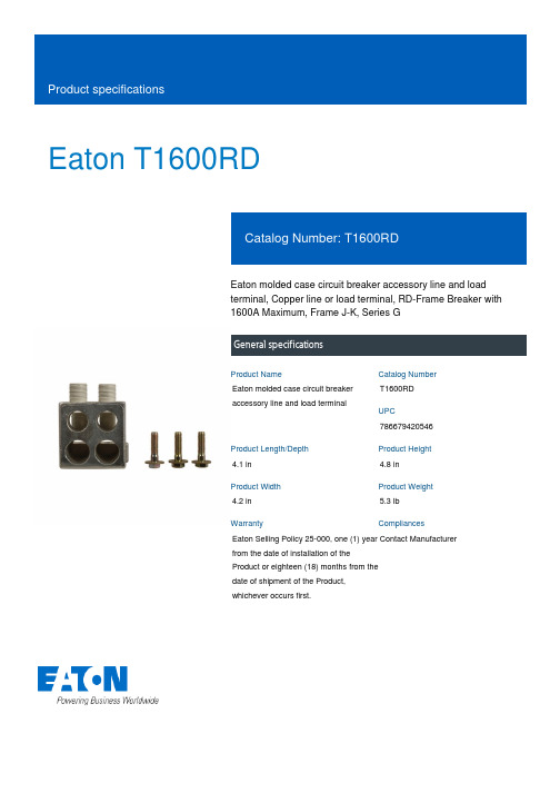
Eaton T1600RDEaton molded case circuit breaker accessory line and load terminal, Copper line or load terminal, RD-Frame Breaker with 1600A Maximum, Frame J-K, Series GGeneral specificationsEaton molded case circuit breaker accessory line and load terminalT1600RD 7866794205464.1 in 4.8 in4.2 in5.3 lb Eaton Selling Policy 25-000, one (1) year from the date of installation of the Product or eighteen (18) months from the date of shipment of the Product, whichever occurs first.Contact Manufacturer Product NameCatalog Number UPCProduct Length/Depth Product Height Product Width Product Weight WarrantyCompliancesFrame J-KUsed with RD-frame Breaker with 1600A Maximum Series GCopper line or load terminalRD-frame breaker with 1600A Maximum Application of Multi-Wire Terminals for Molded Case Circuit Breakers Application of Tap Rules to Molded Case Breaker TerminalsMotor protection circuit breakers product aidPower metering and monitoring with Modbus RTU product aidPlug-in adapters for molded case circuit breakers product aidCurrent limiting molded case circuit breaker module for series G, JG and CLMolded case circuit breakers providing higher levels of selective coordination product aidStrandAble terminals product aidMulti-wire lugs product aidCurrent limiting molded case circuit breaker module product aidHigh performance operating handles for Series G circuit breakers product aidCircuit breaker motor operators product aidSeries G MCCB quick selectorComprehensive circuit protection for control panel applicationsBreaker service centersEaton's Volume 4—Circuit ProtectionMolded case circuit breakers catalogFlex shaft handle installation tutorialEaton Specification Sheet - T1600RDNG and ND-Frame molded case circuit breakersMOEM MCCB product selection guideR-Frame 310+ molded-case circuit breaker 800–2500AFrame size Special features SeriesTypeUsed with Application notesBrochuresCatalogsMultimediaSpecifications and datasheetsEaton Corporation plc Eaton House30 Pembroke Road Dublin 4, Ireland © 2023 Eaton. All Rights Reserved. Eaton is a registered trademark.All other trademarks areproperty of their respectiveowners./socialmedia。
RD600GL通讯管理机使用说明书
RD600GL通讯管理机使⽤说明书RD600GL通讯管理机使⽤说明书(Vision 1.0)(版权所有,翻版必究)2006年7⽉⽬录1 概述............................................. - 1 -1.1 应⽤范围 ................................... - 1 -1.2 主要配置 ................................... - 1 -1.3 性能特点 ................................... - 1 -2 硬件原理及使⽤说明 ............................... - 1 -2.1 装置整体结构 ............................... - 1 -2.2 装置通讯接⼝ ............................... - 2 -3 软件使⽤说明 ..................................... - 3 -3.1 建⽴调试环境 ............................... - 3 -3.2 配置各通道通讯参数⽂件...................... - 1 -3.3 下载配置参数 ............................... - 6 -4 调试⽅法......................................... - 7 -4.1 物理通道测试 ............................... - 7 -4.2 报⽂监视 ................................... - 8 -1概述1.1应⽤范围RD600GL主要应⽤于35K伏以上变电站的远动通讯,作为变电站的通讯⽹关,连接继电保护、测控装置和变电站后台,以及运动系统向调度转发数据;同时⽤于变电站内直流电源系统监控终端的规约转发,环境采集终端的数据转发。
保护600立位患者抬升器说明书

PROTEKT® 600 STAND SIT-TO-STAND PATIENT LIFTMODEL: 34600OWNER’S MANUALThank you for choosing the Protekt® 600 Stand!To better serve you, please record the following information: Supplier Name: _____________________________________ Telephone: ________________________________________ Serial #: __________________________________________ Date of Purchase:__________________________________ INSPECT YOUR MERCHANDISEUpon receipt of your patient lift, verify that all merchandise is complete and free from any shipping damage. Refuse delivery if the packaging appears to be badly damaged. If the merchandise is received damaged or is missing components, contact the shipping company immediately and file a claim.For further assistance, contact your local dealer or Proactive Medical Products at the following:ARNING 6SAFETY PRECAUTIONSThe Protekt® 600 Stand lift allows a caregiver to lift and transfer a patient safely with minimum physical effort. Before attempting to lift anyone, one should practice operating the lift and explain to the patient the lifting procedures.Arrange all necessary items (e.g. lift, sling, commode chair or wheelchair) properly for a smooth procedure.•Special care must be taken with patients who cannot provide assistance while being lifted. (i.e. patients who are comatose, spastic, agitated or otherwise severely handicapped).•The Protekt® 600 Stand should be used solely for transferring a patient from one object (beds, bathtubs, toilets, etc.) to another. The lift should not be used for transporting or moving any patient fromone location to another location.•During lifting or lowering, whenever possible, always keep lift base widened.•Always keep the patient being lifted centered over the base and facing the caregiver operating the lifter.•Do not roll casters over any object while the user is in the sling.•Proactive Medical slings are specially designed to be used in conjunction with Proactive lifts. Do not use slings manufactured byother companies on the lift. Proactive Medical is not responsible forany consequence resulting from the use of non-Proactive slings on this equipment.•Do not put anything (e.g. cushion, pad, etc…..) between the user and the sling. This may cause user to slide out of the sling and causeinjury.•Use only genuine Proactive Medical parts or components. Proactive Medical is not responsible for any consequence resulting from using non-Proactive parts and components.•Service and repair of this equipment should be performed only by an authorized dealer. Proactive Medical is not responsible for anyconsequence resulting from any unauthorized service or repair.•Do not lift over the Maximum Weight limit of 600 lbs.FEATURES C ART:BaseMastControl BoxPendantActuatorLifting BoomKneepad AssemblyFootrest Brake շոչղձճմյնASSEMBLY INSTRUCTIONS:Open the box and take lift out.2.Unscrew nuts and bolts at top and bottom of the mast.3.Attach boom to mast and hand tight bolt and nut.4.Attach the L-shaped arms to back of the kneepad.(For desired height of the kneepad, use proper holes on the L-shaped arms).5.Attach kneepad assembly to the mast.6.Attach actuator and pendant to the control box.STEP 1:Attach the L-shaped arms to the mast.Make adjustment to the desired position.STEP 2:Use the bolt to fasten the L-shaped arms to the Mast.:1.Turn on the power by twisting the RED RESET BUTTON clockwise.2.Press the UP or DOWN button on the hand control once. Check if the batteryindicator lights are on. To proceed with lifting, make sure there is at least one green light. Batteries are fully charged when three (3) green lights are shown.3.After the battery indicator lights go out, push the UP button and the DOWNbutton on the hand control and ensure that the lift is operating correctly.4.Position of the base of lift around or under the object.5.Widen the base and engage the caster bakes.Fitting Stand Assist Sling1.Position the patient in a sitting position.2.Slide the sling down patient’s back to lumbar position.3.Draw the shoulder straps to the front of the patient close to the chest.4.Draw the waist belt around patient’s waist and press together to fasten.5.Attach the shoulder straps to the hooks.Lift and Transfer From Bed1.Fit sling as described in “Fitting Stand Assist Sling”.2.Push lift towards patient. Open the base of the lift.Apply the brakes in both rear casters.3.Position patient’s feet on the foot platform and kneesagainst the knee pad.4.Attached the sling straps to the hooks.5.Have the patient’s hands holding the handles. Forpatient’s who cannot hold the handles, have themhold their arms around the chest.6.Press the “UP” button on the hand control.7.Before the patient’s body is lifted from the bed, stopand make sure the sling is secured and patient’sknees are against the knee pad.8.The patient should be comfortable with the pressureunder the arms. If not, adjust the sling and tryanother loop option to release pressure.9.Press the “UP” button until the patient’s body hascompletely left the bed.10.Transfer to another object can be done at thisposition without the patient attending a full standingposition.11.Release the brakes, close the base, and pull the liftaway from the bed.12.Lower the patient to the object intended.13.To lift patient in a standing position, continue to liftuntil the patient’s knees are locked in a standingposition.14.At the standing position, patient’s knees may moveaway from the knee pad.15.Release the brakes, close the base, and pull the liftaway from the bed.16.Lower the patient to the object intended.17.Reverse the above procedures when lowering thepatient to the bed.Lift and Transfer From Wheelchair1.sling as described in tingAssistush lift towards patient. the baseof the lift to go around the chair. Apply thebrakes in both rear casters.3. patient’s feet on the foot platformand knees against the knee pad.4.Attached the sling straps to the hooks.5. the patient’s hands holding thehandles. patients who cannot holdthe handles, have them hold their armsaround the chest.6. the button on the handcontrol.7. the patient’s body is lifted fromthe chair, stop and make sure the slingis secured and patient’s knees areagainst the knee pad.The patient should be comfortable withthe pressure under the arms. not,adjust the sling and try another loopoption to release pressure.the button until the patient’sbody is completely left the chair.Transfer to another object can be doneat this position without the patientattending a full standing position.11.Release the brakes, close the base, andpull the lift away from the bed.Lower the patient to the object intended.13.To lift patient in a standing position,continue to lift until the patient’s knees arelocked in a standing position.14.At the standing position, patient’s kneesmay move away from the knee pad.15.Release the brakes, close the base, andpull the lift away from the bed.16.Lower the patient to the object intended.17.Reverse the above procedures whenlowering the patient to the bed.USER GUIDECHARGING THE BATTERY -The lift can be charged by plugging the charger directly into the control box w hile it is attached to the lift .OrThe battery pack can be charged while seated in the optional wall /desk charging c addy.OPERATING INSTRUCTIONS — USING THE CONTROL BOX1.If you press either control button (shown at right) for less than 0.5 seconds, you can access the screensshown below.Control ButtonsR Right buttonL Left buttonPressing the left button for more than 0.5 secondswill begin actuatorextension.Pressing the rightbutton for morethan 0.5 secondswill begin actuator retraction.Raise / Lower LiftLong press to raise liftLong press to lower liftbutton to raise or the button to lower the lift.3.Press the 2.OPERATING INSTRUCTIONS —USING THE HAND PENDANTRaise / Lower LiftLong pressto raise liftLong pressto lower lift1.Press thebu�on to raise or the bu�on to lower the li�.•The operator of the lift shall inspect the lift before each use. Check all bolts for tightness. Make sure the base can be easily widened, and that all lift parts are in place. Make sure that casters can be turned freely, and that caster brakes can be engaged. Make certain all necessary items (i.e. slings, andwheelchairs, etc.) are ready for use.•At least once a month, the lift should be thoroughly inspected by a person qualified to recognize any signs of wear and tear, and looseness of bolts orparts. Replace any worn parts immediately.•To lubricate, put a drop of oil on the following points when the lift is placed into service and every month thereafter. Top of Mast, Spreader Hinge, and Casters.WARNING: If you experience a problem with your lift and are unable to service it yourself, contact Proactive Medical or your Proactive authorized distributor.Toileting Sling6Fitting The Toileting SlingSlide the sling down pa �ents back to lumbar posi �on .Draw shoulder straps under the arms and around the chest into the front.Draw Velcro waist belt around waist and press together to fasten.Draw each leg support under the thigh.Crisscross leg straps by feeding one of the leg straps through the other strap.A�ach shoulder straps to hooks in upper ends of the li �ing arms.A�ach leg straps to hooks in the lower ends of the li �ing arms.LIMITED WARRANTY1.. 2.3.4.This warranty shall not apply to any product which has been repaired or altered in any way so as, in our judgment, to affect its functionality and durability, nor to any product subject to abuse, misuse, negligence or accident, improper maintenance, improper installation, nor to any product used with other parts, components and/or accessories with quality and/or specifications not compatible with this product. This warranty does not cover products that have been impaired by occurrences considered Acts of God over which authorized dealer has no control. This warranty shall also be voided if any required periodic maintenance, if applicable, has not been properly performed on this product.This warranty and the aforementioned remedies presented are exclusive and in lieu of all other express or implied warranties. No other representations or claims shall be binding or obligate authorized dealer in any way. Any warranty applicable to this product is limited to the aforementioned period indicated. In no event shall authorized dealer be liable for any special, incidental, or consequential damages; loss of revenue; or cost of replacement goods; resulting from the use or malfunction of this product to the associated equipment on which and with which it is used. This warranty gives specific legal rights and you may be entitled to other rights that vary from state to state.。
戴森超音速吹风机用户手册说明书
目录页数特性和优势3零配件组装6使用和操作7 LED显示灯的故障诊断7滤网清洁8零配件指导9部件识别图(分解图)10热线诊断12安全警告20戴森两年保修期21高压高速的气流高速喷射而出,实现可控的吹干和造型。
周围的空气被吸入并产生形成3倍的气流。
戴森第九代数码马达其转速相比其他吹风机马达快8倍,而重量却减半。
在手持处的气流倍增技术每秒推动13公升的空气。
全面稳定的气流快速吹干不只是需要高速的气流,对双组加热元件进行智能调整。
因为戴森独有设计的减震系统。
戴森第九代数码马达每分钟旋转高达110,000次,产生一种人耳听不到的频率。
没有格栅的出风口设计,带给客户更好的体验效果负离子技术避免静电产生。
内置强劲数码马达戴森第九代数码马达叶片增加至13片,每分钟旋转高达110,000次。
马达旋转时产生3.5kPa的压力。
转速相较于其他吹风机一部分马达高8倍,而重量却减少了一半。
简易的过滤器清洁方法只需转动一下,松开即可清洁过滤器。
4 supersonic环形元件构造未产生加热情况下的环形加热双栈元件磁性连接设计唯一一款配有磁性连接设计的机器, 可以快速方便地更换或转动风嘴减震支架橡胶安装架可帮助防止马达接触 手柄时的震动,从而降低马达和 壳之间的噪音传递只需转动一下,松开 即可清洁过滤器特性和优势脉宽调制精确控制加热元件LED 显示灯清晰地显示选项设置4档精确温度设置 • 快速吹干和造型 • 常规吹干• 轻柔吹干(头皮模式) • 恒冷风 3档风速设置: • 快速 • 常规 • 造型 Cool shot 按钮 自定义设计发型.消音技术同时降低了机器内部和外部的噪音,但是 并没有牺牲其干发的速度。
简易的存储方式为了快速,方便的存储,可以 使用挂绳和防滑垫磁性连接设计独一无二的吹风机体验,磁性连接设计,可以快速方便地更换或转动风嘴。
隔热可触碰技术通过Heat Shield 隔热技术,风嘴表面可保持低温, 即便长时间使用也可随时触碰风嘴。
PJB D-600 低音电子设备说明书

PJB D-600OWNER’S MANUALThank you for purchasing the PJB D-600. A great deal of dedication and passion went into designing and building this no compromise, high performance compact amplifier. It was conceived to be a dedicated amplifier for the “connoisseur” bassist. Reading this manual will enable you to get the best performance from it so that you may enjoy many years of service.READ THIS FIRST•Before using the D-600 please read ALL the instructions.•On receipt of product, check for any signs of physical damage arising from shipping. If any damage is visible contact your dealer.•Keep all original packing.•Do not use this amplifier in a way that would compromise its ventilation system.When operating, never cover the heat sink on rear panel.•Do not locate this amplifier near any heat source.•This amplifier must be connected only to a power source specified in this manual.•For safety do not leave the amplifier plugged into a power source for long periods of time when not in use.•Do not let any liquid or foreign objects fall into any openings on the amplifier.•Never use this amplifier if it has:1. Suffered any physical damage.2. Been subjected to any liquids, rain or moisture.3. Damaged cables connected to it.If any of the above occurs, the amplifier should be examined by qualified servicepersonnel.•Always operate this amplifier with the correctly rated fuse.•Never use this amplifier without proper grounding.•The mains plug is used as disconnect device, the disconnect device shall remain readily operable.•Protective earthing terminal. The apparatus should be connected to a mains socket outlet with a protective earthing connection.• Correct Disposal of this product. This marking indicates that this product should not be disposed with other household wastes throughout the EU. Toprevent possible harm to the environment or human health fromuncontrolled waste disposal, recycle it responsibly to promote the sustainablereuse of material resources.•The apparatus shall not be exposed to dripping or splashing.FRONT PANEL AND BACK PANEL OVERVIEWFRONT AND BACK PANEL DESCRIPTION1. INSTRUMENT INPUT JACK CHANNEL AThis is a standard ¼ inch mono jack socket. This is a high impedance input that can be used with Piezo pickups on double basses.2. CLIP/ MUTE INDICATORWhen the amplifier output is clipping, the LED will light up with red. When muted, the LED will light up with green.3. INPUT GAIN SWITCH CHANNEL AHigh: Higher sensitivity, high impedance input.Low: Lower sensitivity input setting for guitars with onboard electronics.Mute: mute the input stage, when switch on, the clip LED will light up with green.4. INPUT LEVEL SENSITIVITY CHANNEL A5. LOW BASS EQ CONTROL.This will adjust the fundamental tones of E and A strings on 4 string basses and B, E & A on 5 string basses.6. BASS EQ CONTROL.This will adjust the fundamental tones of D and G-strings on 4 & 5 string basses.7. MID RANGE EQ CONTROL.8. LOW TEBLE EQ CONTROL.9. HIGH TREBLE (PRESCENCE) EQ CONTROL.10. COMPRESSOR THRESHOLD LEVEL CONTROL.This will vary the level the limiter threshold. The compression ratio is 3dB to 1. Adjust this to suit your playing style and output power of your instrument. The blue LED will light up when the signal is being compressed. This will vary on how hard the instrument is played and how the threshold is adjusted.11. AUX INPUT VOLUME CONTROLUse to control the level of backing/rhythm track.12. HEADPHONE OUTPUT JACKThis jack accepts ¼ inch stereo headphone jacks.13. MASTER VOUME CONTROL.This is the master volume control and it controls how much power you send to your speakers as well as the line out socket on the back of the amp. When setting up your tone or plugging in your instrument, you should keep this control at a low level. All instruments are different when it comes to how much output is from the pickups. Likewise for players, depending on how hard or soft you play.14. INSTRUMENT INPUT JACK CHANNEL BThis is a standard ¼ inch mono jack socket. This is a high impedance input that can be used with Piezo pickups on double basses.15. CLIP/ MUTE INDICATORWhen the amplifier output is clipping, the LED will light up with red. When muted, the LED will light up with green.16. INPUT GAIN SWITCH CHANNEL AHigh: Higher sensitivity, high impedance input.Low: Lower sensitivity input setting for guitars with onboard electronics.Mute: mute the input stage, when switch on, the clip LED will light up with green.17. INPUT LEVEL SENSITIVITY CHANNEL B18. LOW BASS EQ CONTROL.This will adjust the fundamental tones of E and A strings on 4 string basses and B, E & A on 5 string basses.19. BASS EQ CONTROL.This will adjust the fundamental tones of D and G-strings on 4 & 5 string basses.20. MID RANGE EQ CONTROL.21. LOW TEBLE EQ CONTROL.22. HIGH TREBLE (PRESCENCE) EQ CONTROL.23. LIMITER IN/OUT SWITCH.Sends signal through limiter or bypass.24. COMPRESSOR INDICATOR.This blue L.E.D (Light Emitting Diode) will light up when the signal is being compressed. This will vary on how hard the instrument is played and how the threshold is adjusted.25. AUX INPUT JACKStereo input for Drum machine or I-pod/MP3 player.26. LINE INPUT.Input matched to accept high-level outputs from other bass/guitar pre-amps. This input is a direct feed to the power amp and does not pass through limiter or EQ sections.27. POWER ON/OFF SWITCH.This switches the main power on and off in the amplifier. When you turn on the power, it will have about 2 seconds delay to protect the speaker.Do not leave the amplifier plugged into a power source for long periods of time when not in use.28. AC INPUT -VOLTAGE SELECTOR.Switches the amplifier to run on either 110-115volt or 220-240volt AC power. Never try to run the amplifier on a 220-240volt supply when switched to 110-115volt. This can possibly cause major damage to the amplifier.29. AC INPUT SOCKET & FUSE.Connects the amplifier to AC power supply. Always use a grounded plug and make surethe AC cable is more than 3A rating at 250-volt AC. If you require a longer AC power cord, we recommend the PJB heavy-duty 20 foot power cords. These are available as an accessory. If fuse needs replacing, use a slow blow ¾ inch fuse.30. BALANCED LINE OUT.This is an ultra-low impedance (200Ω) balanced line out for use with recording or PA mixing consoles. This output is not controlled by the volume control. Changing the level on your instrument will however, vary the DI output.31. GROUND LIFT SWITCH.This allows the grounding of balanced out socket to be disconnected. This is useful if you are experiencing hum caused by grounding loops/problems.32. TUNER OUTConnect to instrument tuner. This output can also be used as an additional line out.33. PRE-AMP OUT.Can be used for driving a second amplifier.34. FX SEND SOCKET.Connect the FX send to auxiliary FX unit input.35. FX RETURN SOCKET HIGH.Connect the FX Return to auxiliary FX unit output.36. LOUDSPEAKER OUTPUTS (NEUTRIK SPEAKON CONNECTORS).The D-600 amplifier will work on any load from 16Ω down to 2Ω, which is the safe maximum load for this amplifier. The ‘Speakon’ sockets are in parallel so connecting two 8Ω speakers will result in a 4Ω total load. We recommend that you use PJB high current speaker cables: which are dedicated high-current, low-resistance cables. Using inferior cables will greatly impair the performance of your system.Just to avoid any confusion, a speaker that has a low impedance has a greater load on the amplifier. So a maximum load refers to a minimum speaker impedance as more current is flowing through the amplifier’s output stage, speaker cables and cabinets.OPERATION & POSITIONINGTURN THE VOLUME DOWN on the D-600 before plugging in your instrument.Connect the speaker or speakers to the D-600. For best results with this amplifier you should use PJB loudspeaker cabinets and PJB cables.ALWAYS USE A HIGH QUALITY GROUNDED AC POWER CABLE. NEVER USE THIS AMPLIFIER WITH THE GROUND CONNECTION REMOVED. We recommend you use PJB cables for speaker connections as they have virtually no loss so there is maximum transfer of power from amplifier to speaker.Setting Up the LimiterAlthough a limiter is not essential to bass amplification, it can be a useful tool in smoothing out the character of your instrument or playing style. The D-600 limiter has a preset compression ratio of 3 to 1. For each additional increase of 3dB above the set threshold, the increase in level is actually 1dB. So the dynamic range of your instrument is reduced.First set up the limiter by having the compression control (10) set fully clockwise. Now switch on the limiter (23). Start playing and turn control (10) counter-clockwise. You will see the blue light start to come on and that is the indication that the limiter is now working. Set this control to suit your taste.TRANSPORTING AND STORING THE D-600When transporting or storing the D-600, it is recommended that you always use the gig bag provided. That will ensure that you amp has the best protection from dust and will stay looking like new.When Storing:•Keep in a dry location preferably at room temperature in the gig bag.•Do not store in temperatures below -20 Degrees C or above 40 Degrees C.•Do not allow it to get wet. If this occurs, never turn it on in this condition.•Do not leave the D-600 permanently connected to a power source.SPECIFICATIONS AmplifierPJB 600watt, D class amplifier with digital switch mode power supply. Frequency Response30Hz -25KHzSignal to Noise RatioBetter than 90 dB (EQ off, Volume on Full.)ImpedanceHigh Input: >4MΩ/22pFLow Input: >100KΩ/22pFLine Input: >75KΩPre Amp Line Out: < 2KΩBal. Out: <200ΩLevelsHigh Input: 10mV-2.5VLow Input: 20mV-5VPre Amp Out: 1.2VFX send: 1VBal. Line Out: Typical 500mVCompressor / LimiterGain: 0dBCompression Ratio: 3dB: 1dBEQ CENTER FREQUENCIES50Hz, 160Hz, 630Hz, 2.5KHz, 12KHz at +/- 18dBIncluded Parts6 ft AC Power Cord.Padded gig bag with shoulder strap.SERVICE/WARRANTY INFORMATIONIN USAThe D-600 has a limited warranty period of 2 years, starting from the date of purchase. The buyer must complete and return the enclosed warranty card within 14 days of purchase. In other countriesPlease contact the local distributor as other warrantee terms may apply.This warranty covers defect in materials or workmanship that occurs in normal use. Within warranty period PJB will repair or replace the defect unit free of labor and parts charge. It is the buyer’s responsibility to use the unit strictly according to instructions written in this manual and amplifier manual.This warranty is not transferable; it is provided to original owner only. Damage/defectscaused by the following conditions are not covered by this warranty:•Improper handling, neglect or failure to operate the unit in compliance with the instructions given in user manual;•Connection or operation of the speakers in any way that does not comply with the technical or safely regulations applicable in the country where the product is used;•Repairs or modifications by anyone other than authorized PJB service agent; •Damages/defects caused by force majeure or any other condition that is beyond the control of PJB.Should you need any warranty service, please bring the D-600 back to the dealer from whom you purchased, along with your sales receipt. Depending on the complexity of the repair work, your dealer may return the defect unit to PJB service center for repair or replacement.Phil Jones BassAmerican Acoustic Development LLC8559 Page AvenueSt. Louis, MO 63114 USAPhone: 314 814 3383Fax: 636 536 1338******************************Phil Jones Bass is a division of American Acoustic Development LLC.。
- 1、下载文档前请自行甄别文档内容的完整性,平台不提供额外的编辑、内容补充、找答案等附加服务。
- 2、"仅部分预览"的文档,不可在线预览部分如存在完整性等问题,可反馈申请退款(可完整预览的文档不适用该条件!)。
- 3、如文档侵犯您的权益,请联系客服反馈,我们会尽快为您处理(人工客服工作时间:9:00-18:30)。
RD600T1型微机变压器差动保护2007年10月使用说明书V1.011、概述概述装置适用于110KV 及以下电压等级系统中双圈变压器的主保护。
完善的设计保证了装置可以在恶劣环境下长期、可靠地运行。
现场总线技术和标准通信规约的适用,保证了自动化系统通讯的可靠性、快速性和易用性。
2、主要功能主要功能 2.1 保护功能配置:差动速断保护二次谐波制动的比率差动保护 软件调整各侧CT 相位差 变压器本体保护 CT 断线告警CT 断线闭锁比率差动可选2.2 数据采集功能电流实时采集变压器各侧三相电流IA、IB、IC2.3 事件记录保护事件 告警事件 遥信变位事件 操作记录事件2.4 通讯功能高速光电隔离RS485总线2.5 故障记录及查询功能大屏幕液晶/中文汉字显示3、保护配置及工作原理保护配置及工作原理 3.1 3.1 差动差动差动速断保护速断保护速断保护当变压器任一相差电流大于差动速断保护定值,保护瞬时动作,用于快速切除变压器内部严重故障。
差动速断定值按躲过外部故障时最大不平衡电流和励磁涌流整定。
23.23.2 比率差动保护比率差动保护本装置采用比率制动特性的差动保护,动作特性如下图所示。
差动动作判据为:当Izd < Igd 时 Icd > Iqd当Izd ≥ Igd 时 Icd > Iqd + K * (Izd - Igd)装置采用按相判别,当三相任一相满足上面动作判据之一时,差动保护动作出口。
其中:Icd —— 差动电流 Izd —— 制动电流Iqd —— 差动电流动作门槛值(差动启动电流) Igd —— 拐点电流Kzd —— 比率制动系数Icd = ∣I1 + I2∣Izd = ∣I1 - I2∣/ 2 (I1 — 高压侧电流;I2 — 低压侧电流)注意:高低压侧电流接入本装置时电流必须反相接入。
3.3 3.3 二次谐波制动比率差动二次谐波制动比率差动二次谐波制动比率差动二次谐波制动判据为:I2 > K2 × I1式中: I1 --- 差电流的基波分量;I2 --- 差电流的二次谐波分量; K2 --- 二次谐波制动系数;当变压器任一相差流满足制动条件即闭锁比率差动保护。
3.3 CT 断线报警断线报警与闭锁与闭锁与闭锁当任一相的差电流大于10% 额定电流,且该相某一侧电流小于10% 额定电流,则装置判定为该相CT 发生断线,经过10秒延时,装置发出告警信号。
I zdgdI qd I cd当装置判出CT发生断线时,立刻闭锁比率差动保护,但发CT断线告警信号要经过10秒。
发生CT断线是否闭锁比率差动保护,用户可通过控制字选择。
本体保护3.4 4 本体保护本体保护对于变压器本体保护,其相应动作接点通过本装置重动出口并记录动作事件。
保护定值表及说明4、保护定值表及说明序号 定值名称定值范围说明序号1 KZ1 控制字1 见下表 1字节2 KZ2 控制字2 见下表 1字节3 Isd 差动速断电流 (1~99)A, 步长0.01A 2字节4 Iqd 差动启动电流 (1~10)A, 步长0.01A 2字节5 Igd 差动拐点电流 (1~10)A, 步长0.01A 2字节6 Kzd 比率制动系数 (0.1~1), 步长0.01 2字节7 Kxb 二次谐波制动系数 (0.1~0.5), 步长0.01 2字节8 IeH 高压侧二次额定电流 (1~10)A, 步长0.01A 2字节9 IeL 低压侧二次额定电流 (1~10)A, 步长0.01A 2字节KZ1(控制字1)各位定义如下:(1-投入;0-退出)D7 D6 D5 D4 D3 D2 D1 D0D0 差动速断保护投退 D4 备用D1 比率差动保护投退 D5 备用D2 CT断线告警投退 D6 备用D3 CT断线闭锁投退 D7 备用KZ2(控制字2)各位定义如下:(1-投入;0-退出)D7 D6 D5 D4 D3 D2 D1 D0D0 本体重瓦斯保护投退 D4 本体轻瓦斯保护投退D1 调压重瓦斯保护投退 D5 调压轻瓦斯保护投退D2 压力释放保护投退 D6 油温高保护投退D3 风冷消失保护投退 D7 油温低保护投退36、RD6RD60000系列系列安装开孔尺寸安装开孔尺寸安装开孔尺寸455、RD600T1型微机型微机变压器变压器变压器保护装置保护装置保护装置端子图端子图端子图本体保护输入备用本体出口跳低压侧开关跳高压侧开关-KM备用压力释放调压重瓦斯本体重瓦斯名 称名 称RD600T1型微机变压器差动保护端子图设 计校 核制 图审 核标准化批 准日 期珠海瑞捷电气有限公司RD 图 号:Ia1Ia1*Ib1*Ib1Ic1Ic1*Ia2*Ia2Ib2*Ib2Ic2*Ic2高压侧电流低压侧电流保护出口名 称本体保护出口名 称开入公共负端备用开入3RS485-A RS485-B 通讯屏蔽地CAN-A CAN-B通讯接口开关输入量编号A03A04A05A06A07A08A09A10A11A12A13A14A15A16A17A18A19A20A01A02B15B14B13B12B11B10B09B08B07B06B05B04B03B02B01B20B19B18B17B16编号C15C14C13C12C11C10C09C08C07C06C05C04C03C02C01C20C19C18C17C16编号D24D21D22D23D15D14D13D12D11D10D09D08D07D06D05D04D03D02D01D20D19D18D17D16编号电源输出本体重瓦斯调压重瓦斯压力释放风冷消失本体轻瓦斯调压轻瓦斯油温高油位低备用开入2备用开入1跳高压侧开关跳低压侧开关信号公共端保护跳闸告 警装置故障中央信号备用出口1备用出口2AC/DC+AC/DC-装置电源屏蔽地+24V -24V67、 调试大纲调试大纲 7.17.1 差动差动速断保护校验速断保护校验速断保护校验① 参照图1-1接线;② 将差动速断投入,整定控制字1令KZ1=0000 0001[01];③ 按下表整定差动速断电流,在各相分别通入单相电流,逐渐增大电流,直至差动速断保护动作。
测量动作电流值,记入下表。
保护动作时,测量B01-B02、B03-B04、B05-B06、B07-B08端子应分别导通, 面板“跳闸”灯亮。
如有条件,也可用微机保护测试仪在两侧加入两个电流来测试,注意两个电流必须反相加入。
高压侧电流测试:中点侧电流测试:差动速断定值(A)5 10 15 20 测A 相动作电流 (端子D01-D02) 动作值 差动速断定值(A)5 10 15 20 测B 相动作电流 (端子D03-D04) 动作值 差动速断定值(A)5 10 15 20 测C 相动作电流 (端子D05-D06)动作值差动速断定值(A)5 10 15 20 测A 相动作电流 (端子D07-D08) 动作值 差动速断定值(A)5 10 15 20 测B 相动作电流 (端子D09-D10) 动作值 差动速断定值(A)5 10 15 20 测C 相动作电流 (端子D11-D12)动作值Ia1 Ia1* Ia2 Ia2*图1-177.2 7.2 比率差动保护校验比率差动保护校验比率差动保护校验 7.2.1 7.2.1 差动差动差动启动电流启动电流启动电流校验校验校验① 参照图1-1接线;② 将比率差动保护投入,整定控制字1令KZ1=0000 0010[02];③ 将差动拐点电流整定为5.00A,即令Igd=5.00A。
在各相分别通入单相电流,逐渐增大电流,直至比率差动保护动作。
保护动作时,测量B01-B02、B03-B04、B05-B06、B07-B08端子应分别导通, 面板“跳闸”灯亮。
高压侧电流测试:中点侧电流测试:7.2.2 7.2.2 比率制动系数校验比率制动系数校验比率制动系数校验① 参照图1-1接线;④ 将比率差动保护投入,整定控制字1令KZ1=0000 0010[02];⑤ 将差动启动电流整定为2.00A,即令Iqd=2.00A,差动拐点电流整定为5.00A,即令Igd=5.00A,按下表在高压侧、低压侧同时加入两个电流,直至比率差动保护动作。
保护动作时,测量B01-B02、B03-B04、B05-B06、B07-B08端子应分别导通, 面板“跳闸”灯亮。
注意:加入的两个电流必须反相加入!计算公式:设高压侧电流为I1,低压侧电流为I2,则差动电流为:Icd=I1-I2,制动电流为Izd=1/2(I1+I2),则比率制动系数为:K=(Icd – Iqd)/( Izd - Igd),差动速断定值(A)1 2 3 4 测A 相动作电流 (端子D01-D02) 动作值 差动速断定值(A)1 2 3 4 测B 相动作电流 (端子D03-D04) 动作值 差动速断定值(A)1 2 3 4 测C 相动作电流 (端子D05-D06)动作值差动速断定值(A)1 2 3 4 测A 相动作电流 (端子D07-D08) 动作值 差动速断定值(A)1 2 3 4 测B 相动作电流 (端子D09-D10) 动作值 差动速断定值(A)1 2 3 4 测C 相动作电流 (端子D11-D12)动作值8其中:Iqd------差动启动电流,Igd------差动拐点电流⑴ 当Izd=1/2(I1+I2)=6.00A 时,理论值I1=7.20A,I2=4.80A。
实验时,I1=7.20A 固定不动,I2加5.00A,然后I2以0.01A 的级差递减,直至保护动作。
记下此时的I1和I2,即可按上式求出K 值。
⑵ 当Izd=1/2(I1+I2)=8.00A 时,理论值I1=9.60A,I2=6.40A。
实验时,I1=9.60A 固定不动,I2=6.70A。
重复上述步骤。
数据记入表4-2。
7.3 本体本体保护保护保护校验校验校验① 参照图1-2接线;注:图中未画出 C08、C09、C10端子,其接法同C07一样。
② 将本体保护全部投入,则整定控制字2即令KZ2=1111 1111[FF];③ 将端子A08分别和端子C04-C10分别短接,则各本体保护分别动作,保护动作时,液晶屏幕上会显示相应信息,同时当本体重瓦斯、调压重瓦斯、压力释放动作时,测量B01-B02、B03-B04、B05-B06、B07-B08端子应分别导通, 面板“跳闸”灯亮。
而当风冷消失、本体轻瓦斯、调压轻瓦斯、油温高、油温低动作时,测量B16-B19端子应导通, 面板“告警”灯亮。
制动电流 (A) 6 8 理论制动系数Kzd0.4 0.4 测A 相比率差动 (电流需反相加入)实测Kzd制动电流 (A) 68 理论制动系数Kzd0.4 0.4 测B 相比率差动 (电流需反相加入)实测Kzd制动电流 (A) 6 8 理论制动系数Kzd0.4 0.4 测C 相比率差动 (电流需反相加入) 实测Kzd图1-2风冷消失开入公共端本体重瓦斯 调压重瓦斯 压力释放97.4 C 4 CT T 断线断线告警告警告警校验校验校验 ① 参照图1-1接线;② 将CT 断线告警投入,整定控制字1令KZ1=0000 0100[04];③ 在Ia1、Ia2加入两个同相等值电流,电流值大于10%额定电流,拉掉任一相电流持续10秒,装置发CT 断线告警信号;发告警信号时,测量B16-B19端子应导通,面板“告警”灯亮。
