铝电解电容器的使用说明书
铝电解电容器使用指南(中文PDF)
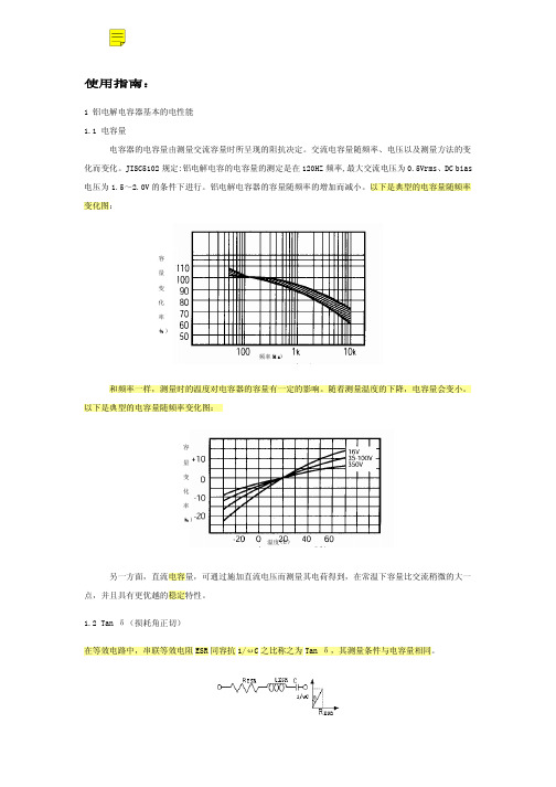
8 组装使用 8.1 组装使用时,请遵守以下内容:电容器的端子间不要直接接触,另外,不要让导体物质引起正负极 短路。 8.2 请确认所安装电容器所处环境 a) 不要与水或油污接触或处于结露状态 b) 不要让日光、O3,紫外线及放射线直接照射到电容器上 c) 不要处于充满有害气体的环境(硫化氢、亚硫酸、亚硝酸、氨水、CI2 等) d) 震动及冲击不要超过样本或规格说明中规定值:
1.3
1.4
1.6
1.65
寿命的推算公式,原则上适用于周围环境温度为+40℃到最高工作温度范围内,但由于封口材料的老 化等因素,实际的推算寿命时间一般最大为 15 年。
(表 2-1 寿命推算曲线)
3. 冗余电压
铝电解电容器先充电,再放电,而后再将两引线短接,再将其放置一段时间后,两端子间存在电压上 升的现象;由这种现象所引起的电压称之为再生电压。当电压施加在介质之上时,在介质内部引起电子的 转移,从而在介质内部产生感应电场,其方向与电压的方向相反,这种现象称之为极化反应。在施加电压 引起介质极化后,如果两端子进行放电一直到端子间的电压为零,而后将其开路放置一段时间后,一种潜 在的电势将出现在两端子上,这样就引起了再生电压。再生电压在电容器开路放置 10~20 天时达到峰值, 然后逐渐降低,再生电压有随元件变大而增大的趋势(基板自立形)如果电容器在产生再生电压后,两端 子短路,瞬间高电压放电可能引起组装线上的操作员工的恐惧感,并且,有可能导致一些低压驱动元件(如 CPU,存储器等)被击穿的危险,预防出现这种情况的措施是在使用前加 100Ω~1KΩ的电阻进行放电,或 者在产品包装中用铝箔覆盖引起两端子间短路。 4. 极性
铝电解电容器的使用说明书分析
铝电解电容器的使用说明书铝电解电容器如在非规定条件下使用的话,会导致爆炸失火等重大故障,请先确认下述注意事项后使用。
工作温度与纹波电流1.检查电容器的工作和安装环境,确保在产品目录或规格书的规定条件下。
2.工作温度、纹波电流应在规定的范围内,电容器如通过太大电流则引起异常发热、短路、失火等致命不良。
3.电容器本身为发热元件,会使机器内温度上升,这点请注意,确认机器正常状态下,电容器周围的温度。
4.允许通过的纹波电流应随环境温度(电容器周围的温度)上升而降低,允许通过纹波电流应考虑最高环境温度。
5.电气参数随着频率的变化而变化。
选好电容器必须考虑频率的变化。
特别需要注意无论在低频和高频使用时,电容器的自身发热会使等效串联电阻和自感变化,缩短了使用寿命。
施加电压和其它工作条件1.电容器有极性,施加反向电压或交流电压后,会导致压力阀释放或短路失火等致命不良。
交流电压情况下使用特殊的交流电容器。
2.在极性转换电路中请使用双极性电容,但这种情况不使用于交流电路。
3.不要施加过电压,即直流电压上叠加交流成分时,峰值不要超过额定电压,否则会引起短路失火等致命重大不良。
4.浪涌电压有严格的条件限制,在此条件下不能保证长时间工作。
工作电压即使短时间内也不要超过额定电压,请慎重选择电容器。
5.多只电容器并联时,应考虑导线电阻,使每个电容器上的导线电阻值相等。
6.多只电容器串联时使用同一规格的电容,请并联均压电阻,设计时要考虑这时加在电容上的电压完全一样,确保施加在电容器上的电压不超过额定电压。
7.使用电容器时需要考虑设备的使用寿命。
超过使用寿命时,继续使用则电容器存在压力阀释放或短路隐患,定期点检时按需替换。
8.不能用于重复急剧充放电电路。
熔接机器等充放电时,电容器请特别设计。
一些旋转设备的控制电路,如伺服驱动和充放电电路中选用合适的电容器,请与海立联系。
9.即使非快速充放电,但电压变化大则会导致寿命特性恶化,要实际上机认真确认或与海立联系。
正确使用铝电解电容器的方法
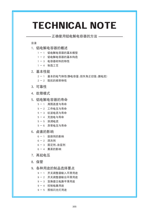
(图-9)是电容器等效电路的简化模型。(图14)的虚线部分 代表这个电路中的组成成分(C,R,L)。从图可得之,阻抗-频率特 性是由C,R,L的频率特性组合而成。
1/ωC是容抗,图中容抗的直线向下角成45°角。ωL是感抗, 它的直线向右上角成45°角。R代表等效串联电阻。在低频率区间, 有频率依存性的电介质损失影响大,因而 R曲线向下。在高频区间, 电解液和电解纸的阻值占主导地位,不再受频率的影响,因而R值 趋于稳定。阻抗表达式如式(3)所示。
封口材料
目录中记载的内容有可能未经提示而变更。贵司在购买、使用时请要求敝司提供规格书,并以此为基准去使用。
356
CAT. No. C1001O
正确使用铝电解电容器的方法
1-3 电容器材料的特性
铝箔是铝电解电容器主要材料,将铝箔设置为阳极,在电解液 中通电后,铝箔的表面会形成氧化膜(Al2O3),此氧化膜的功能为电 介质。 如图-5所示,形成氧化膜后的铝箔在电解液中是具有整流特性 的金属,被称之为阀金属。
③ 裁剪
按照不同产品的尺寸要求将铝箔 (阴极箔和阳极箔)和电解纸剪切为 需要的尺寸
④ 卷绕
将阴极箔和阳极箔之间插入电解 纸,然后卷绕成圆柱形,在卷绕工艺 上阴极箔和阳极箔上连接端子。
铝 箔
立创片式铝电解电容器规格书说明书
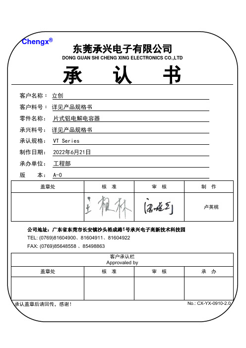
公司地址:广东省东莞市长安镇沙头裕成路1号承兴电子高新技术科技园81604911、81604922版 本version日 期Date A-02022/6/21第一次发行卢英桃变更申请记录/Change Request Record变更内容 Change The Content制 作ProducerPart Number System(产品编码)12345679101112131415182021TOL.CodeLG LR 104J B P0ER PR 224K C PH MV 334L D VT VD 474M E SM SX 105N F KS KF 225G GM KM 335I GS EF 475K ZF GR 106L LF GF 226N EL AL 336O KL HL 476P FL GL 107Q ML ZL 227R PL RL 337S LM LK 687T LH LL 158U NM NS 229X NP NH 339CodeBP PZ 479G6MZ FZ 10T 5D LZ PF 15T 5E AP PE 22T 5T LS LP 33T 6B FP PN 10M 7G MN MG 22M 9MBPG187A512C5D5E5F516G51720212530354045458161719COLORSHAPERROBlack SERIESCAPCITANCEVOLTAGECASE SIZETYPESLEEVEOTHERSCase Size Liameten BackgroundCode Special 0.1±5%40043 Bulk 0.22±10% 6.36R34PCB Termial 80085Ammo Taping H No special Green L Violet Other trademark Navy blue 0.47±20%10010 6.3 2.0mm Pitch 2.5mm Pitch T250.33±15% 3.5mm Pitch T20Light purple 1±30%160168Sky blue 3.303503512.5 5.0mm Pitch T50Coffee 2.2-20%5005016Lead Cut & FormT35-40%2502510Orange red 1006306318C-Type CXX Transparentblue 4.7V-Type VXX 22-20%8008022E-Type 12012030Q-Type EXX 3310%10010025QXX 10040%16016035P-Type PXX 47-20%Printing color 220-10%20020040W-Type WXX Black 1HXX 33020%22022051K-Type GoldenKXX White 2680025025063.5H-Type 150020%31531576Y-Type22000035035090I 3300050%400400Len.(mm)47000-5+204204206100000450450 5.4150000500500 5.5220000550550 5.8PET S E Plane F 3300006006006.2PVC9V-chipConvex T 10000007.7Snap-in V18010.522000001212.513.514.515.51616.517202125303540Code Code W AC X V R Code WO X0G0VXCXSeries Cap(MFD)Tolerance VoltageCode Feature Code Z Ø8 F=2.5mm Finite height KSpecial voltageMSpecial capacitanceS T Transparent yellowYSleeve MaterialCode Rubber Shape Code 4Silvery 3YXX V-CHIPNB116.17.18 CODE Polymer NB2V序号No 目录INDEX页page1 概述SCOPE 32 外形尺寸图及尺寸表Case size table 33 技术性能 SPECIFICATIONS 44 称电容量、额定电压、额定纹波电流与外形尺寸对应表Nominal capacitance, rated voltage, rated ripple current and casesize table5-65 构造图及材料表 Frame drawing and materials 76 试验方法及要求 TESTS8-117 标志 Marking 128 片式铝电解电容的编带V- Chip Type Aluminum Electrolytic Capacitors13一、概述 SCOPE本产品规格书适用于东莞承兴电子科技有限公司VT型片式铝电解电容器产品。
铝电解电容器 GRSeries 商品说明书
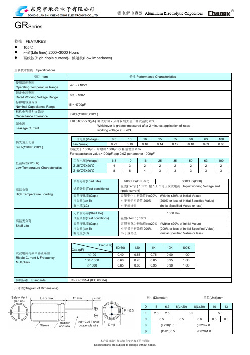
铝电解电容器Aluminum Electrolytic Capacitors GR Series特性FEATURES⚫105℃⚫寿命(Life time):2000~3000 Hours⚫高纹波(High ripple current)、低阻抗(Low Impedance)主要技术性能Specifications项目Item 特性Performance Characteristics使用温度范围Operating Temperature Range-40 ~ +105℃额定电压范围Rated Working Voltage Range6.3 ~ 100V标称电容量范围Nominal Capacitance Range15 ~ 4700μF标称电容量允许偏差Capacitance Tolerance±20%(120Hz,+20℃)漏电流Leakage Current L≤0.01CV or 3(μA) 测试时间2分钟取最大值,测试温度20℃;Whichever is greater measured after 2 minutes application of ratedworking voltage at +20℃损失角正切值tan δ(120Hz,+20℃)工作电压(Voltage) 6.3 10 16 25 35 50 63 100 tan δ(max)0.22 0.19 0.16 0.14 0.12 0.10 0.09 0.08 容量大于1000μF,每增加1000μF损耗值增加0.02For capacitance value>1000μF,app 0.02 per another 1000μF低温特性(120Hz)Low Temperature Characteristics 工作电压(Voltage) 6.3 10 16 25 35 50 63 100 Z-25℃/Z+20℃ 4 3 2 2 2 2 2 2 Z-40℃/Z+20℃8 6 4 3 3 3 3 3高温负荷High Temperature Loading 负荷寿命(Load Life) 2000Hrs(D:5~6.3) 3000Hrs(D≥8)试验条件(Test conditions)温度(Temp.) 105℃输入工作电压纹波电流(Input working Voltage andripple current)容量变化率(Cap.) 容量变化为初始值的±20% (Within ±20% of Initial Value)损失角(tan δ) 小于等于初始值200% (200% or less of Initial Specified Value)漏电流(LC) 小于规格值(Initial Specified Value or less)高温无负荷Shelf Life 无负荷寿命(Shelf life) 1000 Hrs试验条件(Test conditions) 温度(Temp.) 105℃容量变化率(Cap.) 容量变化为初始值的±20% (Within ±20% of Initial Value)损失角(tan δ) 小于等于初始值200% (200% or less of Initial Specified Value) 漏电流(LC) 小于规格值(Initial Specified Value or less)纹波电流与频率补正系数Ripple Current & Frequency MultipliersFreq.(Hz)Cap.(μF)50(60) 120 1K 10K 100K ≤100 0.40 0.55 0.75 0.90 1.00100~1000 0.60 0.70 0.85 0.95 1.00≥1000 0.65 0.80 0.95 0.98 1.00参照标准Standards JIS- C-5101-4 (IEC 60384)尺寸图(Diagram of Dimensions):.尺寸(Diameter): 单位(Unit):mmD 5 6.3 8(L<20) 8(L≥20) 10 13F 2.0 2.5 3.5 5.0d 0.5 0.5 0.6 0.6 0.6α(L<20)1.5 (L≥20)2.0β(D<20)0.5 (D≥20)1.0Voltage(Code) 6.310 16 Cap.(μF) D x L IMP R.C D x L IMP R.C D x L IMP R.C 100 5*11 0.580 140 5*11 0.58 140 6.3*12 0.250 300 120 5*11 0.530 165 5*11 0.53 140 6.3*12 0.250 320150 6.3*12 0.250 185 6.3*12 0.25 340 6.3 *12 0.220 340 8*12 0.150 500180 6.3*12 0.250 255 6.3*12 0.250 340 6.3*12 0.220 340 8*12 0.150 580220 6.3*12 0.250 275 6.3*12 0.220 340 6.3*12 0.220 340 8*12 0.150 600270 6.3*12 0.220 280 6.3*12 0.220 3408*12 0.150 640 8*12 0.130 580330 6.3*12 0.220 340 6.3*12 0.220 3408*12 0.130 640 8*12 0.130 580 8*12 0.130 640390 8*12 0.130 600 8*12 0.130 640 8*12 0.130 640470 8*12 0.130 640 8*12 0.130 6408*12 0.130 640 10*13 0.100 865560 8*12 0.130 640 8*12 0.130 640 10*13 0.100 880680 8*12 0.130 640 8*12 0.130 6408*16 0.087 750 10*13 0.087 8658208*12 0.130 64010*13 0.080 865 10*17 0.075 1210 10*13 0.110 86510008*12 0.130 640 8*16 0.087 76010*17 0.075 1210 10*13 0.087 865 10*17 0.075 121012008*16 0.096 84010*20 0.060 1400 10*20 0.060 1400 10*13 0.087 88015008*20 0.069 105010*20 0.060 1430 10*20 0.060 1430 10*17 0.069 12101800 10*20 0.060 1400 10*20 0.060 1460 10*25 0.052 1650 13*20 0.046 19002200 10*20 0.060 1460 10*20 0.060 1490 13*20 0.045 19202700 10*25 0.050 1650 10*25 0.050 1650 13*25 0.040 2124 13*20 0.050 1650 13*20 0.035 19003300 10*25 0.050 165013*25 0.030 2124 13*20 0.050 18703900 13*20 0.046 19004700 13*25 0.046 2124﹡13mm may be replaced by 12.5mm upon customer’s request.Voltage(Code) 2535 50 Cap.(μF) D x L IMP R.C D x L IMP R.C D x L IMP R.C33 6.3*12 0.500 23039 6.3*12 0.500 26547 6.3*12 0.250 300 6.3*12 0.500 29556 6.3*12 0.250 315 8*12 0.420 51568 6.3*12 0.240 340 8*12 0.420 53582 6.3*12 0.220 320 8*12 0.230 625 8*12 0.420 555100 6.3*12 0.220 340 8*12 0.220 640 10*13 0.200 760120 8*12 0.200 565 8*12 0.200 6558*16 0.200 730 10*13 0.200 780150 8*12 0.180 580 8*12 0.180 670 10*17 0.130 825180 8*12 0.150 600 10*13 0.130 7608*20 0.130 825 10*17 0.130 855220 8*12 0.130 6208*12 0.130 64010*17 0.130 875 8*16 0.100 83010*13 0.100 8302708*12 0.130 64010*17 0.075 1210 10*25 0.093 1025 10*13 0.100 8253308*12 0.130 6658*20 0.087 105013*20 0.090 166010*17 0.075 86510*13 0.100 845 10*17 0.075 1210390 10*13 0.100 865 10*17 0.075 1210 13*20 0.090 16804708*16 0.087 84010*17 0.075 1210 13*25 0.088 1950 10*13 0.100 885560 10*17 0.075 1210 10*20 0.060 1380 13*25 0.088 1970 680 10*17 0.075 1210 10*20 0.058 1400820 10*20 0.060 1370 10*25 0.054 1650 13*20 0.046 19001000 10*20 0.058 1400 13*20 0.046 1920 13*25 0.042 21241200 10*20 0.055 14201500 10*25 0.050 1650 13*20 0.047 19001800 13*25 0.043 21042200 13*25 0.040 2124Voltage(Code) 63100 Cap.(μF) D x L IMP R.C D x L IMP R.C15 6.3*12 1.880 11522 6.3*12 1.050 115 8*12 1.530 23027 6.3*12 1.050 120 8*12 1.320 23233 6.3*12 1.050 125 8*12 1.280 33039 8*12 0.800 200 8*16 0.980 30047 8*12 0.780 212 10*13 0.650 37056 8*12 0.760 222 8*20 0.480 36268 10*13 0.750 234 10*17 0.460 35782 10*13 0.700 314 10*20 0.430 4661008*16 0.630 30010*20 0.430 480 10*13 0.580 314120 10*17 0.324 357 13*20 0.368 530 150 8*20 0.324 362 13*20 0.357 680 180 10*20 0.190 466 13*25 0.328 750 220 10*20 0.190 466 13*25 0.328 880 270 13*20 0.128 670330 13*20 0.128 690390 13*25 0.118 922﹡13mm may be replaced by 12.5mm upon customer’s request.。
铝电解电容器指产品的使用手册-NCC
铝电解电容器指产品的使用手册-NCC [文档标题]
铝电解电容器使用手册-NCC
[章节1:产品介绍]
[内容]
在本章节中,将介绍铝电解电容器的基本知识和产品特点。
包括电容器的构成、工作原理、适用范围等等。
[章节2:产品规格]
[内容]
本章节详细描述了铝电解电容器的规格参数。
包括容量、电压等级、尺寸、温度特性等等。
[章节3:安装与接线]
[内容]
本章节将提供铝电解电容器的安装指南。
包括安装位置选择、安装过程步骤、接线方法等等。
[章节4:使用及维护]
[内容]
本章节将详细介绍如何正确使用铝电解电容器,并提供维护方法。
包括使用注意事项、存储条件、维护周期等等。
[章节5:故障排除]
[内容]
本章节将常见的故障情况,并提供相应的排除方法和建议。
包括电容器不工作、温度过高等问题的解决方法。
[章节6:安全警示]
[内容]
在本章节中,提供了与铝电解电容器相关的安全警示信息。
包括使用过程中的安全注意事项、避免火灾和触电等相关警示。
[附件]
附件1:铝电解电容器产品规格表
附件2:电容器安装示意图
[法律名词及注释]
1、电容器:指具备存储电荷并能释放电能的器件。
根据构造和材料的不同可分为不同种类,如铝电解电容器、电解电容器等。
2、规格参数:是指衡量产品性能的各项指标。
3、安装位置选择:根据具体应用场景选择最佳的安装位置。
4、维护周期:指对产品进行检查和保养的时间间隔。
[全文结束]。
UT系列V-chip铝电解电容器商品说明书

供应商:客户:MESSRS制品名贴片型铝电解电容器220UF35V 10*10.2100UF80V10*10.233UF100V 10*10.22000HPRODUCT NAME:V-chip Aluminum Electrolytic Capacitors 系列:UT SERIES:UT Series,105︒C,±20%,Standard规格料号:(详见电气参数及料号)DESCRIPTIONMaterial NO:(See electrical parameters and material number)客户承认栏发行确认栏APPROVAL COLUMN APPROVED BY审核CHECKED BY 确认APPROVED BY 审核CHECKED BY 确认APPROVED BY何远娣林洁芝发行日期Release Date:2021年01月11日发行编号:Issue NO:CU20210111006承认书SPECIFICATIONS FOR APPROV AL签认后,敬请惠返一份,多谢!Please chop,sign and return to us a copy after approval.Thank you!UT SERIES V-chip Aluminum Electrolytic Capacitors1.范围:Scope适用“UT系列”立式片式铝电解电容器This specification covers“UT Series”V-chip aluminum electrolytic capacitors.2.参考标准:Reference Standard国际标准IEC60384与日本工业标准JIS C-5101The international standard IEC60384and Japanese industrial standard JIS C-5101.3.环境保护标准:Environmental Protection Standard遵照欧盟指令2002/95/EC.Comply with the EU directive2002/95/EC.4.使用温度范围:Operating Temperature Range-55︒C~+105︒C5.电压范围:Voltage RangeDC:4~100V6.容量范围:Capacitance RangeCAP:0.47~2200μF7.容量偏差范围:Capacitance Tolerance±20%at120Hz,+20︒C8.漏电流:Leakage Current2分钟后读数(After2minutes of reading)I≤0.01CV or3(μA)whichever is greater9.损耗角:Tanδ测试频率:120Hz,温度:20℃Measurement frequency:120Hz,Temperature:20︒CRated Voltage(V)4 6.310162535506380100 Tanδ(max.)0.350.300.240.200.180.160.140.140.140.1410.低温特性:Stability at Low Temperature测试频率:120Hz(Measurement frequency:120Hz)Low Temperature Stability Impedance Ratio(MAX)Rated Voltage(V)4 6.310162535506380100 Z-25︒C/Z+20︒C(120Hz)<Ф87432222222≥Ф87543222222UT SERIES V-chip Aluminum Electrolytic Capacitors120Hz Z-40℃/Z+20℃(120Hz)<Ф815884433333≥Ф815108643333311.耐久性:Load Life105℃施加额定电压2000小时后,放置16小时后,电容器应满足以下要求After applying rated voltage with max ripple current for2000hrs at+105℃,and then resumed 16hours,the capacitors Shall meet the following requirements.容量变化率Capacitance Change ±30%初始值内Within±30%of initial value损耗角正切值Dissipation Factor ≤200%初始规定值Not more than200%of the specified value漏电流Leakage Current ≤初始规定值Not more than the specified value12.高温储存:Shelf Life105℃贮存1000小时后,放置16小时后,电容器应满足以下要求After storage for1000hrs at+105℃,then resumed16hours,the capacitors Shall meet the following requirements容量变化率Capacitance Change ±30%初始值内Within±30%of initial value损耗角正切值Dissipation Factor ≤200%初始规定值Not more than200%of the specified value漏电流Leakage Current ≤300%初始规定值Not more than300%of the specified value13.耐焊接热:Resistance to Soldering Heat在250℃的条件下,电容器在热板上保持30秒,然后从热板上取下电容器,让其在室温下恢复,电容器应满足以下要求:The capacitors shall be kept on then hot plate maintained at250℃for30seconds.After removing from the hot plate and restored at room temperature,they meet the following requirement:容量变化率Capacitance Change ±10%初始值内Within±10%of the initial value损耗角正切值Dissipation Factor ≤初始规定值Not more than the specified value漏电流Leakage Current ≤初始规定值Not more than the specified value14.标识:Marking电容器标识内容如下:Capacitors shall be legibly marked with the following:1)产品系列:Manufacture’s mark2)额定电压和额定电容:Rated voltage and nominal capacitanceUT SERIES V-chip Aluminum Electrolytic Capacitors3)负极标识:Negative polarity15.图样:Drawing (Unit:mm)(∅4~∅6.3)(∅8~∅10)(≥∅12.5)U TSERIESV-chip Aluminum Electrolytic CapacitorsPlastic platformPlastic platform16.尺寸:Dimensions (Unit:mm)SizeФ4×5.4Ф5×5.4Ф6.3×5.4Ф6.3×7.7Ф6.3×10.2Ф8×6.5Ф8×10.2Ф8×12.5A 1.8 2.1 2.4 2.4 2.4 2.9 2.9 2.9B 4.3 5.3 6.6 6.6 6.68.38.38.3C 4.3 5.3 6.6 6.6 6.68.38.38.3E 1.0 1.5 2.1 2.1 2.1 3.1 3.1 3.1L 5.45.45.47.710.26.510.212.5H 0.5~0.90.8~1.1Size Ф10×10.2Ф10×12.5Ф12.5×13.5Ф12.5×16.5A 3.2 3.2 4.0 4.0B 10.310.313.013.0C 10.310.313.013.0E 4.5 4.5 4.4 4.4L 10.212.513.516.5H0.8~1.1 1.0~1.417.编带说明:Taping Specifications符合标准JIS C0806与IEC 602863Applicable standard JIS C0806and IEC 60286.(US、UT、UE、UN、UH、UW、UL、UD series)17.1.盒带图样与尺寸Carrier Tape and DimensionFig.1(D≤ 10mm 以下产品)Fig.2(D≥Φ12.5mm 以上产品)UTSERIESV-chip Aluminum Electrolytic Capacitors尺寸SizeW(MM)P(MM)F(MM)A0(MM)B0(MM)T2(MM)S形状ApplicableΦ4*5.4128 5.5 4.5 4.5 5.8--Fig.1Φ5*5.41212 5.5 5.6 5.6 5.8--Φ6.3*5.416127.57.07.0 5.8--Φ6.3*7.716127.57.07.08.2--Φ6.3*10.216127.57.07.010.5--Φ8*6.516127.58.68.67.0--Φ8*10.2241611.58.78.711.0--Φ8*12.5241611.58.78.713.0--Φ10*10.2241611.510.710.711.0--Φ10*12.5241611.510.710.713.0--Φ12.5*13.5322413.714.014.014.228.4Fig.2Φ12.5*16.5322413.714.014.017.528.417.2.卷盘:ReelUTSERIESV-chip Aluminum Electrolytic CapacitorsA32.0∅50 Min.13±0.52317.3.包装数量:Package quantity规格Specification卷装数量Quantity/Reel盒装数量Quantity/BagA±0.3(MM)B±2(MM)Φ4*5.42000pcs20000pcs14382Φ5*5.41000pcs10000pcs14382Φ6.3*5.41000pcs10000pcs18382Φ6.3*7.71000pcs10000pcs18382Φ6.3*10.2700pcs7000pcs18382Φ8*6.51000pcs10000pcs18382Φ8*10.2500pcs5000pcs26382Φ8*12.5400pcs4000pcs26382Φ10*10.2500pcs5000pcs26382Φ10*12.5400pcs4000pcs26382Φ12.5*13.5200pcs1600pcs34382Φ12.5*16.5200pcs1600pcs34382Φ16*16.5125pcs250pcs46332Φ16*21.575pcs150pcs46332Φ18*16.5125pcs250pcs46332Φ18*21.575pcs150pcs46332Φ20*16.5100pcs200pcs46332Φ20*21.550pcs100pcs4633218.无铅回流焊接:Lead-free Reflow Soldering ConditionA.回流焊条件推荐:Recommended Conditions for Reflow Soldering:(1)应采用红外线及热风回流焊接,不宜采用汽相加热回流焊接;A thermal condition system such as infrared radiation(IR)or hot blast should beadopted,and vapor heat transfer systems(VPS)are not recommended.(2)推荐回流焊只进行一次,回流焊次数如果需要二次,必须相隔30分钟以上;Reflow soldering should be performed one time.If the capacitor has to be reflowedtwice,30minutes must be layout between each time.(3)无铅回流焊,请符合下述条件:For lead-free type reflow soldering,please observe proper conditions below: UT SERIES V-chip Aluminum Electrolytic CapacitorsB.表面安装推荐尺寸:Recommended Land Size(Unit:mm)尺寸Size X Y a尺寸SizeX Y aΦ4 1.6 2.6 1.0Φ12.5 3.0 6.0 4.0Φ5 1.6 3.0 1.4Φ16 3.27.0 6.0Φ6.3 1.6 3.5 1.9Φ18 3.28.0 6.0Φ8 2.5 3.5 3.0////Φ10 2.5 4.0 4.0////UT SERIES V-chip Aluminum Electrolytic Capacitors19.引线原材料:The Raw Materials of Lead WireName MaterialPercentage TPCSFe 71.35%Cu 20%Sn8.65%20.电容器代码标志:Explanation of Part Number1234567891011121314Series Voltage (WV)Capacitance ( F)Cap.Tol.(%)Case Size Type/CodeSeries:产品系列Voltage:产品额定工作电压Capacitance:产品标称静电容量Cap.Tol:产品静电容量误差范围Case Size:产品外壳尺寸Type/Code:产品加工形状例如:Example:UT1V221M1010VG产品加工形状Type/Code :片式产品外壳尺寸Case Size :10*10.2产品静电容量误差范围Cap.Tol :±20%产品标称静电容量Capacitance:220μF 产品额定工作电压Voltage:35V 产品系列Series:UT21.结构:ConstructionUTSERIESV-chip Aluminum Electrolytic Capacitors-底座Base plate 铝壳Aluminum case铝箔(阳极和阴极)Aluminum foil (Anode &cathode foil)电解纸Electrolytic paper电解液Electrolytic封口胶粒Rubber seal引出线Lead wire22.额定纹波电流的频率导数:Frequency Coefficient of Allowable Ripple CurrentFrequency 50Hz 120Hz 300Hz 1kHz ≥10kHz Coefficient0.701.001.171.361.5023.电气参数及料号:Electric parameter and Material number电气参数:Electric parameter料号:Material Number 24.片式铝电解电容器一般使用注意事项Application guideline for V-CHIP aluminum electolytic capacitors A)电路设计:Circuit Design1)充分考虑电容器使用和安装条件在产品目录的规定范围内.Please make sure the environmental and mounting conditions to which the capacitor will be exposed are within the conditions specified in catalogue.NOSerie sName (WV /uF)DΦ*LCap.tol.(%)120Hz 20℃DF (%)120Hz 20℃≤LC (uA)(2min)≤E ±0.5Allowable ripple current (mA rms)at 105 C,120HzESR 100KHz (Ω)20℃≤Remarks1UT 220UF35V 10*10.2±201677 5.0230//2UT 100UF80V 10*10.2±201480 5.0175//3UT 33UF100V10*10.2±201433 5.0136/////////////NO Series Name DΦ*L Material number Remarks1UT 220UF35V 10*10.2UT1V221M1010VG /2UT 100UF80V 10*10.2UT1K101M1010VG /3UT 33UF100V10*10.2UT2A330M1010VG///////2)工作温度和施加的纹波电流应在产品目录的规定范围内.Operating temperature and applied ripple shall be within specification.3)在设计电路时,应选择符合寿命要求的产品.Appropriate capacitors which comply with the life requirement of the products should be selected when designing the circuit.4)铝电解电容器是有极性的,不应加反向电压或交流电压。
MURATA 聚合物铝电解电容器 说明书

C90C.pdf 10.12.28
电压 (VDC)
产品一览
Capacitance Value:电容值(µF)
6.8 8.2
10
15
22
33
47
56
68
82 100 150 180 220 270 330 470
2 4 6.3 10 12.5 16 D4
70
聚合物电容和 MLCC 解决方案
D4 D4
D4
静电容量 公差
%
20 20 20 20 20 20 20 20 20 20 20 20 20 20 20 20 20 20 20 20 20 20 20 20 20 20 20 20 20 20 20 20 20 20 20 20 20
代号
D4 D4 D4 D4 D6 D6 D4 D4 D4 D6 D6 D9 D4 D4 D4 D4 D4 D4 D6 D9 D4 D4 D4 D6 D9 D9 D4 D4 D4 D6 D6 D9 D9 D4 D4 D4 D6
16
9
9
D4 D4 20 16
D4 D6 D6 16 12 10
D4 D6 D6 67 6
D9 8
D4
D4 D4 D4
D4
D4 D6
D9
55
45
25
25
15
15
10
10
D4
D4 D4
55
28
25
D6
D9 D9
15
10
10
D4 D4 D4 D6 D6 D9
D9
55
45
30
25
20
20
12
D4 D4 D6 60 40 30
铝电解电容 说明书

+ 铝电解电容应用指南 2005.02这个应用指南这个应用指南是铝电解电容的完全手册,当然重点是CDE的型号。
它从结构上深入的揭示了世界上主要的铝电解电容型号的性能和应用的最新信息。
希望你能告诉我们更多你所想知道的,使我们能够完善这本手册。
铝电解电容总论除了一些表面安装技术(SMT)的铝电解电容有固态的电解液之外,一般的电解电容都有一个卷绕电容元件,然后注入电解液,连上端子,密封装入一个罐里。
这个卷绕电容元件包含了一个阳极金属箔,浸透在电解液中的纸隔离物和阴极金属箔。
这个金属箔是高纯度的铝,它的表面用蚀刻技术蚀刻了几十亿的细微管道以增加与电解液的接触面积。
看起来电容量是在两个金属箔之间,实际上是在阳极金属箔和电解液之间。
正极板是阳极金属箔;电介质是阳极金属箔上的绝缘铝氧化物;真正的负极板是导电的液态电解质,阴极金属箔仅仅是连接电解液。
这个结构能产生巨大的电容量,因为蚀刻金属箔可以增加100倍以上的表面积并且铝氧化物的电解质的厚度不超过1微米。
这样的电容器有很大的金属盘面积并且金属盘非常靠近。
这些电容器一般提供0.1UF---3UF的电容值,额定电压从5V---500V。
他们是有极性的器件,有明显的正负极端子,并且有非常多的各种各样的类型,包括浇铸和罐型的SMT的器件,轴向和经向引线罐型,牛角端子型和大罐,螺栓端子型。
最典型的电容电压值是330UF/100V 和6800UF/10V SMT器件100UF/450V,6800UF/50V,10000UF/10V 微型罐型1200UF/450V 和 39000UF/50V 牛角罐型9000UF/450V和390000UF/50V 大罐,螺栓端子型如果两个相同容量的铝电解电容串联,背靠背连接正极端子和负极端子,结果是一个有一半电容值的无极性电容。
两个电容调整所承担的电压,其作用相当于被二极管旁路过来的电压。
当加上电压,极性正确的电容器承担全压。
在无极性的铝电解电容和马达启动铝电解电容里一个第二阳极金属箔替代阴极金属箔,结果在一个壳里里得到一个无极性的电容器。
湖南艾华集团股份有限公司-EGH1EM221F12OTGOS0-铝电解电容器说明书
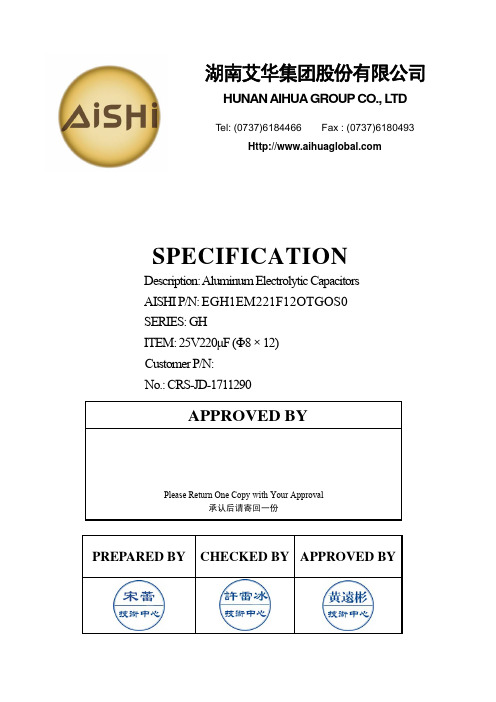
PREPARED BY CHECKED BY APPROVED BYSPECIFICATIONDescription: Aluminum Electrolytic Capacitors AISHI P/N: EGH1EM221F12OTGOS0 SERIES: GHITEM: 25V220μF (Φ8×12) Customer P/N: No.: CRS-JD-1711290APPROVED BYPlease Return One Copy with Your Approval承认后请寄回一份湖南艾华集团股份有限公司HUNAN AIHUA GROUP CO., L TDTel: (0737)6184466 Fax : (0737)6180493变更记录版本更改原因更改内容生效日期CRS-JD-1711290 新建新建 2017-11-24Customer深圳市仁天芯科技有限公司SERIES GH DATE 2017-11-24FIG-1 TABLE-1No.Customer Part No.Aishi Part No.Capacitance (μF)Toleranceon RatedCapacitance (%)Rated V oltage (Vdc)SurgeV oltage(Vdc)Operating Temp. Range (℃) tan δ (120Hz) (Max) Leakage Current (μA)(2min.)Max Ripple Current(mArms)at105℃100kHz ESR (Ω) at 20℃,100kHz Endurance at 105℃(Hours)Dimensions (mm) Appearance Drawing No. ΦDL αd F 1 EGH1EM221F12OTGOS0 220 ±20 25 32 -40~+1050.18 55 210 0.46 7000 81220.6 3.5 FIG-1注:料号第15码“G ”表示橡胶塞特殊要求,第16码“O ”表示CP 线特殊要求,料号第17、18码“S0” 表示套管体现容量偏差代码的要求。
铝电解电容器使用指南(中文PDF)

铝电解电容器使用指南(中文PDF)铝电解电容器使用指南1.简介铝电解电容器是一种常见的电子元件,具有高电容量和高电压稳定性的特点。
本文档旨在提供有关铝电解电容器的详细使用指南。
2.材料和工具准备在使用铝电解电容器之前,需要准备以下材料和工具:- 铝电解电容器- 电路板- 铅线- 锡焊- 钳子- 鼓风机- 隔热垫3.安装步骤3.1 将铝电解电容器连接到电路板上- 在选定的位置上,将铝电解电容器的正极和负极分别连接到电路板上的正负极引脚上。
- 注意正确安装铝电解电容器的极性,避免正负极连接错误。
3.2 进行焊接- 使用钳子将铅线固定在电路板上的引脚上。
- 使用锡焊将铅线与引脚焊接固定。
3.3 提供良好散热条件- 在电路板周围放置隔热垫,避免热量传导到其他组件。
- 使用鼓风机为铝电解电容器提供良好的散热条件,避免过热引发故障。
4.使用注意事项4.1 避免过高电压- 确保将铝电解电容器的额定电压范围内使用,避免过高电压损坏电容器。
- 在设计电路时,选用合适额定电压的铝电解电容器。
4.2 温度限制- 注意铝电解电容器的工作温度范围,避免过高或过低温度环境下使用。
4.3 极性正确- 使用铝电解电容器时,确保正负极连接正确。
反向使用可能导致电容器破损或发生爆炸。
4.4 长时间存储- 如果需要长时间存储铝电解电容器,在存储期间要保持电容器的干燥状态。
5.附件本文档涉及的附件包括:- 铝电解电容器数据手册- 铝电解电容器安装示意图6.法律名词及注释本文中涉及的法律名词及其注释如下:- 铝电解电容器:一种电子元件,能够存储和释放电荷。
7.结束语本文档提供了关于铝电解电容器的详细使用指南,包括安装步骤、使用注意事项和附件信息。
如有其他问题,请参阅铝电解电容器数据手册或咨询相关专业人士。
铝电解电容器使用指南(中文PDF)

铝电解电容器使用指南(中文PDF)铝电解电容器使用指南1:引言铝电解电容器是一种常用的电子元器件,广泛应用于电路中的滤波、耦合和储能等功能。
本指南旨在介绍铝电解电容器的基本原理、使用方法和注意事项,帮助用户正确选择和使用铝电解电容器。
2:基本原理2.1 铝电解电容器的结构铝电解电容器由电解质、铝箔、隔膜和外壳组成。
其中,电解质是两个电极之间的绝缘物质,铝箔即正负极板,隔膜用于隔离正负极板,外壳则起到保护作用。
2.2 电容器的电容值电容器的电容值取决于电容器的尺寸、电极材料和电解质的种类。
通常用法拉第(F)作为电容值的单位,常见的铝电解电容器容值范围从几微法(F)到数百毫法(F)不等。
3:选择铝电解电容器3.1 工作电压选择铝电解电容器时,需要注意其工作电压是否符合实际应用的需求。
工作电压应略大于电路中的最高工作电压。
3.2 容值根据电路需求,选择合适的电容值。
注意,在高频电路中,电容器的实际电容值会因频率而降低。
3.3 极性铝电解电容器有极性,在安装时必须连接正确。
正极端通常标有“+”符号,负极端则为消极引线。
4:使用铝电解电容器4.1 安装在安装铝电解电容器时,应注意保持电容器干燥和无尘的环境。
正确连接极性,安装时不得施加过大的力以免损坏电容器。
4.2 工作电压与温度铝电解电容器的工作电压和温度密切相关,应确保电解电容器的工作电压和温度在规定范围内。
温度过高会缩短电解质的寿命,降低电容值。
4.3 长寿命和高温型电容器对于需要长时间工作或在高温环境中使用的应用,建议选择具有长寿命和高温型特性的铝电解电容器。
5:注意事项5.1 频率特性铝电解电容器的电容值会随频率的变化而发生变化。
在使用时,应注意频率特性对电容器性能的影响。
5.2 极性错误铝电解电容器是极性元器件,接线时务必正确连接极性。
极性连接错误可能导致电容器损坏甚至发生短路、爆裂等危险。
5.3 耐压电容器的耐压是指电容器能承受的最大工作电压。
铝电解电容器指产品的使用手册-NCC

铝电解电容器指产品的使用手册-NCC铝电解电容器指产品的使用手册-NCC1.引言1.1 目的本手册旨在提供有关铝电解电容器的详细信息,以便用户正确安装、操作和维护该产品。
1.2 适用范围本手册适用于铝电解电容器的所有型号和规格,由NCC公司生产和销售。
2.产品概述2.1 产品介绍铝电解电容器是一种用于存储电能和平滑电流的重要电子元件。
它由铝箔和电解介质构成,具有高电容量、低ESR和长寿命等特点。
2.2 产品分类铝电解电容器根据用途和特性分为多个系列,包括低阻抗型、高温型、超低ESR型等。
3.环境要求3.1 安装环境铝电解电容器应在干燥、防尘、无腐蚀气体的环境下安装。
3.2 工作温度根据产品规格书所示,铝电解电容器在指定的工作温度范围内正常工作。
4.安装与操作4.1 安装准备在安装之前,请确保您已阅读并理解本手册中的安全事项和注意事项。
4.2 安装方法按照产品规格书中的指示进行安装,确保端子正确连接,并且固定牢固。
4.3 使用注意事项避免超过产品规格书中的额定电压和额定温度,防止过电流和过热等情况发生。
5.维护与保养5.1 清洁定期清洁铝电解电容器的表面,确保无灰尘和腐蚀物。
5.2 检查定期检查铝电解电容器的端子和接线,确保连接可靠。
6.故障排除与维修6.1 常见问题与解决方法一些常见问题及其可能的解决方法,如电容值异常、电容器发热等。
6.2 维修与更换如果铝电解电容器出现故障或过期,应进行适当的维修或更换,遵循相关的规程和安全标准。
7.附件本文档涉及以下附件,详见附件清单。
附件清单:- 产品规格书- 安装示意图- 维护记录表8.法律名词及注释8.1 法律名词- 铝电解电容器:根据相关法规定义,指使用铝箔和电解介质构成的电子元件。
- ESR(Equivalent Series Resistance):等效串联电阻,指铝电解电容器内部电阻。
8.2 注释- 安装示意图:为了更清晰的展示安装步骤,故意简化的图示,实际操作请严格按照产品规格书进行。
电解电容器使用方法说明书
电解电容器使用方法说明书一、概述本说明书旨在提供关于电解电容器的使用方法和注意事项的详细说明。
请在使用电解电容器之前认真阅读本说明书,并按照指导进行操作,以确保电解电容器的正常使用。
二、电解电容器的种类电解电容器分为铝电解电容器和钽电解电容器两种。
铝电解电容器适用于一般用途,钽电解电容器适用于高频和小型化的电子设备。
用户应根据实际需求选择合适的电解电容器。
三、电解电容器的使用方法1. 电压极性的连接在使用电解电容器时,应注意其极性。
一般来说,电解电容器具有正负极之分,应根据电解电容器本身的标记或标识,将正极连接到正电源上,将负极连接到负电源或地线上。
接线时应轻拿轻放,避免损坏电容器引脚。
2. 额定电压的选择使用电解电容器时,应根据电路工作电压的要求选择适当的额定电压。
电解电容器的额定电压应大于或等于电路工作电压,以确保电容器在使用过程中不会损坏。
3. 电解电容器的温度范围每种电解电容器都有一定的工作温度范围,用户应根据实际情况选择合适的电容器类型。
在使用过程中,应避免将电容器暴露在过高或过低的温度环境中,以免影响电容器的性能或造成损坏。
4. 电解电容器的极性反转为了防止电解电容器损坏,用户在使用过程中应注意避免出现极性反转的情况。
极性反转可能导致电容器烧毁或发生爆炸。
如需更换或拆卸电解电容器,应先切断电源,并按照正确的极性连接方式进行操作。
5. 电解电容器的装配和固定在安装电解电容器时,应确保电容器引脚与电路板上的焊盘正确对应。
焊接电容器时应注意避免温度过高,以免损坏电容器。
安装完毕后,应检查电容器的固定状态,确保电容器牢固可靠,不易发生松动。
四、电解电容器的注意事项1. 避免振动和冲击由于电解电容器内部结构较为脆弱,因此在使用过程中应避免强烈的振动和冲击,以免引起电容器内部结构松动或破裂。
2. 避免过高温度电解电容器的使用温度应在规定范围内,过高的温度可能导致电容器的性能下降或引起内部电解液的挥发。
高分子(固液混合)固态铝电解电容器使用注意事项说明书
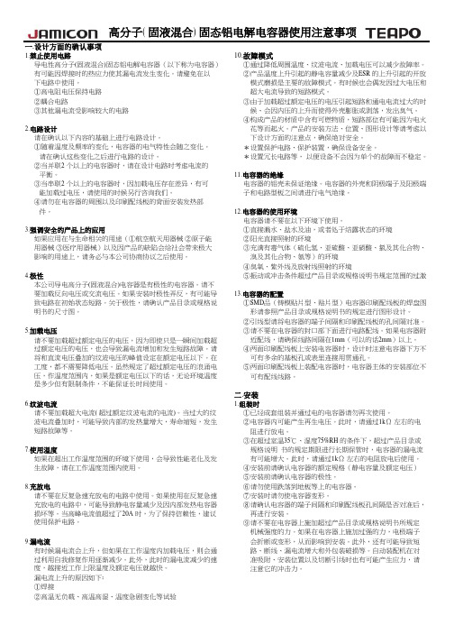
一.设计方面的确认事项1.禁止使用电路10.故障模式导电性高分子(固液混合)固态铝电解电容器(以下称为电容器)①通过降低周围温度、纹波电流、加载电压可以减少故障率。
有可能因焊接时的热应力使其漏电流发生变化。
请避免在以②产品温度上升引起的静电容量减少及ESR 的上升引起的开放下电路中使用。
模式磨损是主要的故障模式。
有时候也会偶发因过大电压和①高电阻电压保持电路 超大电流导致的短路模式。
②耦合电路③由于加载超过额定电压的电压引起短路和通电电流过大的时③其他漏电流受影响较大的电路 候、会因内压的上升而使得外壳膨胀或剥落,发出臭气。
④构成产品的材质中含有可燃物质,短路部位有可能因为电火2.电路设计花等而起火。
产品的安装方法、位置、图形设计等请考虑以请在确认以下内容的基础上进行电路设计。
下设计方面的注意点,确保绝对安全。
①随着温度及频率的变化,电容器的电气特性会随之变化。
*设置保护电路、保护装置,确保设备安全。
请在确认这些变化之后进行电路的设计。
*设置冗长电路等, 以便设备不会因为单个的故障而不稳定。
②当并联2 个以上的电容器时,请在设计电路时考虑电流的 平衡。
11.电容器的绝缘③当串联2 个以上的电容器时,因加载电压存在差异,有可电容器的铝壳未保证绝缘。
电容器的外壳和阴极端子及阳极端 能加载过电压,请使用的时候另行咨询我们。
子和电路型板之间请进行电气绝缘。
④请勿在电容器的周围以及印刷配线板的背面安装发热部 件。
12.电容器的使用环境电容器请不要在以下环境下使用。
3.强调安全的产品上的应用①直接溅水、盐水及油,或者处于结露状态的环境②阳光直接照射的环境③充满有毒气体(硫化氢、亚硫酸、亚硝酸、氯及其化合物、 溴及其化合物、氨等)的环境④臭氧、紫外线及放射线照射的环境4.极性⑤振动或冲击条件超过产品目录或规格说明书规定范围的过激13.电容器的配置①SMD 品(铸模贴片型、贴片型)电容器印刷配线板的焊盘图 形请参照产品目录或规格说明书的规定进行图形设计。
Rubycon MXE系列铝电解电容器规格说明书
APPROVALHIROKAZU HORIKAWAFAX No. +81-265-73-3380DESIGNHIROAKI OKUMURACHECKKOUICHI WADA1938-1, NISHIMINOWA, INA-SHI, NAGANO-KEN, JAPANTEL No. +81-265-72-7116RUBYCON PART No.MXE SeriesDRAWING No.ISSUE DATE 26 April 2022RUBYCON CORPORATIONENGINEERING DIVISIONISSUE No.1REE-050162Messrs. ALMAR ENTERPRISES CO.,LTD.ALUMINUM ELECTROLYTIC CAPACITORSSPECIFICATION SHEETRoHS ComplianceCUSTOMER PART No.6. MarkingUnless otherwise specified, capacitor shall be clearly marked the following items on its body. <Example> Sleeve color: Black, Lettering color: White(1)Trade mark(2)Mark Indicating Electrolytic Capacitor(3)Upper Operating Temperature(4)Rated Voltage(5)Nominal Capacitance (Tolerance)(6)Series (Sleeve material)(7)Polarity(8)Lot No.CE 105℃450V 100 uF(M) MXE(PET)Lot No.7. PERFORMANCE<Table-1>〔Standard Test Conditions 〕Standard conditions: In the absence of provision, test and measurement shall be conducted in the following standard condition.Temperature :15℃~35℃Relative Humidity :25%~75%Atmospheric Pressure :86kPa ~106kPa 〔Post Processing 〕If there are no provision, please leave the capacitor in the standard conditions for 1~2 hours. <Condition ><Criteria>Not more than the value of Table-2<Condition >Measuring Frequency :120Hz±20%Measuring Voltage :Not more than 0.5Vrms Measuring Temperature :20±2℃Measuring Circuit :Series circuit<Criteria>The value of Table-2( -20 ~ +20 % )<Condition >Measuring Frequency :120Hz±20%Measuring Voltage :Not more than 0.5Vrms Measuring Temperature :20±2℃Measuring Circuit :Series circuit<Criteria >Not more than the value of Table-2<Definition ><Criteria >The value of Table-2〔Frequency Coefficient 〕〔Temperature Coefficient 〕 1.252.26Ambient Temperature (℃)Temperature coefficient shows the limit that can pass the ripple current exceeding the rated ripple current (table 1) at each temperature when the life expectancy of the capacitor becomes nearly equal.Coefficient 1.00 1.88Coefficient3005001k 10k≤0.801.4010585Nominal Capacitance (Capacitance Tolerance)Dissipation Factor (tanδ)Rated Ripple CurrentThe rated ripple current is the maximum A.C.current at 120Hz which can be applied at maximum operating temperature.The combined value of the D.C.voltage and the peak A.C.voltage shall not exceed the rated voltage.60(50) 1.20120(100)As a post processing after the test, please leave the capacitor in the measurement temperature(20℃±2℃) for enough time until whole of it reaches the measurement temperature.1Leakage Current23465≥Frequency (Hz)1.001.15D.C. voltage applied to capacitors to measure leakage current shall be controlled so that the voltage reaches the rated voltage within one minute. Leakage current shall be measured for 5minutes after the D.C.voltage applied has reached the rated voltage across a 1000 ±10 ohm series protection resistor.(20±2℃)<Condition >Capacitance, D.F. and Impedance shall be measured at 120Hz.<Criteria ><Condition >Impedance shall be measured at -25℃, 20℃ and 120Hz.<Criteria >Z(-25℃) : Impedance at -25℃ Z(20℃) : Impedance at 20℃<Condition ><Criteria ><Condition ><Criteria >6Low Temperature Stability Impedance Ratio(MAX)SurgeThis item provides for overvoltage at abnormal situations, and not be hypothesizing that overvoltage is always applied.The capacitor shall be applied surge voltage through a (100±50) / CR <KΩ> resistor in series for 30±5 seconds in every 6±0.5 minutes at 15 ~ 35℃. The procedure shall be repeated 1000times.Then the capacitors shall be left under the normal temperature and normal humidity for1 to 2hours before measurement. [CR : Nominal Capacitance (μF )]Leakage CurrentSTEP2Impedance Ratio The ratio of STEP 1 and STEP 2 shall be less than value of Table-1-6STEP3Z(-25℃) / Z(20℃)Rated Voltage (V.DC)400 ~ 4508Items Required performanceDissipation Factor Not more than the value of Table-2〃Within ±10% of the initial value Dissipation Factor No visible damage and clearly markingNot more than the value of Table-2Leakage Current Not more than the value of Table-2Appearance7Within ±15% of the initial value Dissipation Factor Not more than the value of Table-2Not more than the value of Table-2Appearance No visible damage and no leakage of electrolyteCapacitance Change 8Resistance to Soldering Heat◇Solder bath methodTerminals of the capacitor shall be immersed into solder bath at 260±3°C for 10±1 seconds up to 2.0 to 2.5mm from the body of capacitor.Then the capacitor shall be left under the standard conditions for 1 to 2 hours before measurement.◇Solder iron method370±10℃(Soldering Iron top) 5±1sec.ItemsRequired performanceCapacitance Change 5Variation of Characteristics by TemperatureSTEPTesting Temperature (℃)Time120±2Time to reach thermal equilibrium2-25±3〃3105±2Capacitance ChangeWithin ±20% of the value of STEP 1Leakage CurrentNot more than 8 times the value of Table-2<Condition ><Criteria ><Condition >D.C.voltage and rated ripple current shall be applied to capacitors for a period of 2000 +72/0 hoursat maximum operating temperature ±2℃.The D.C.voltage and peak A.C.voltage combined must not exceed the rated voltage.The capacitors under test shall be protected against direct heat radiation from the heat source.After the test, the capacitor shall meet the following requirements.<Criteria ><Condition ><Criteria ><Condition >◇Tensile Strength of Terminals◇Bending Strength of Terminals<Criteria >No visible damage.<Condition ><Criteria >Leakage Current Not more than the value of Table-2Not more than 200% of the value of Table-211Shelf Life TestAfter capacitors shall be stored at maximum operating temperature ±2℃ for a period of 1000+48/-0 hours with no voltage applied, then the capacitors shall be left under the normal temperature and normal humidity for 16 hours before measurement.(If any doubt arises on the judgment, the capacitors shall be subjected to the voltage treatment in JIS C 5101-4,4.1.)Dissipation Factor Not more than 200% of the value of Table-2AppearanceNo visible damage and no leakage of electrolyte.Leakage Current Not more than the value of Table-2ItemsRequired performanceCapacitance Change Within ±20% of the initial valueThe capacitor shall be stored in the ambient of 40±2℃ and relative humidity 90~95% for 240±8 hours.After the test, the test sample shall be stored under normal temperature and normal humidity for 1~2 hours before measurement.At least over 95% of circumferential surface of dipped portion of the terminal shall be covered with new solder.Required performanceTerminals of the capacitor shall be immersed in flux (ethanol solution of the rosin, 25 wt%rosin) and shall be immersed in the solder bath.Solderability9Resistance to Damp Heat(Steady State)ItemsRequired performanceCapacitance Change Within ±20% of the initial valueDissipation Factor 13AppearanceNo visible damage and no leakage of electrolyte.No visible damage and clearly marking, no leakage of electrolyte.12Terminal StrengthThe body of capacitors shall be fixed and the tensile force of 20N(2.0 kgf) shall be applied to the terminal in the lead out direction of the terminal for 10±1 secondsThe body of capacitors shall be fixed.The weight of 25N(2.5 kgf) shall be applied to the terminal in the perpendicular direction against the lead out direction of the terminal at the part of 1.6mm from the body for 30±5 seconds.At this time, if permanent change occurs in the terminal , the weight shall be removed,and the terminal shall be made straight to be the original form.Then the weight shall be applied in the opposite direction with the same way.10EnduranceCapacitance Change Within ±10%of the initial value Dissipation Factor Not more than the value of Table-2Leakage Current Not more than the value of Table-2AppearanceItems<Condition >Vibration frequency range : 10 to 55Hz Peak to peak amplitude : 1.5mmSweep rate: 10 to 55 to 10Hz, In about 1min<Criteria ><Condition >◇D.C. reverse voltage method<Criteria >The capacitor shall meet the either of the following two requirement.① When the pressure relief vent operates, a flame shall not be observed or neither some piece ofelements nor cases shall disperse, And a capacitor shall not be in a dangerous state. ② The vent shall not operate for 30 minutes and any abnormalities shall not be observed.8. Factory9. Indication of Lot No□ □ □ □ □Factory code・・・Rubycon Corporation, Main Plant A ・・・Akita Factory.I ・・・P.T. Rubycon IndonesiaTwice of Manufactured day Manufactured month(Manufactured month : October = O, November = N, December = D)Manufactured year (the last one digit of A.D)10. Structure of Electrolytic Capacitors№12345678910111213Separator Electrolytic Capacitor Paper Electrolyte Etylene glycol ItemsRequired performanceManufacturing FactoriesResistance toVibrationTesting shall be done out in 3 AXIS for 2 hours each (total 6 hours) as below.Fix it by using mounting device separately.Within ±5% of the initial valueAppearanceNo visible damage and clearly marking, no leakage of electrolyte.Cathode Foil Vent TestCapacitor shall be subjected to D.C. current given in the table below at reverse polarity.1Φ22.4 or less P.T. Rubycon IndonesiaLot 224, Batamindo Industrial park, Mukakuning, Batam, INDONESIABlank Winding Tape PP Anode Tab RivetAluminum Cathode Tab Aluminum SleeveP.E.T.Appearance :Black Rubycon Corporation, Akita Factory 1-1,Tateai Aza uenodai,Yurihonjyou-city,Akita-pref,JAPANAluminumName 14 more than Φ22.4Norminal body diameter of the capacitorD.C.current (A)Capacitance Change Anode FoilAluminum AddressMaterial NoteAluminum 15Rubycon Corporation, Main Plant 1938-1,Nishi-minowa,Ina-city,Nagano-pref,JAPAN10Aluminum TerminalSPCC Cu over 2μm + Sn over 6μmTerminal Board Rubber(EPT)Terminal Board Bakelite Case11. Compliance for RoHS Directive12. Export Trade Control Ordinance13. Notes on use of aluminum electrolytic capacitors(1)Charge and dischargeDo not use for the circuit that repeats quick charge or discharge.(2) External stressDo not apply excessive force of pushing, pulling bending, and/or twisting to the main body and terminals.(3) Heat resistance at soldering process(4) Insulation and PC board mounting(5) Adhesives and coating materialsDo not use the adhesives and coating materials that contain halogenated organic solvents or chloroprene as polymer.(6) StorageStorage time after shipment from Rubycon factory is less than 2 years.<Storage Condition>**Aluminum electrolytic capacitors should not be stored in damp conditions such as water, saltwater spray or oil spray.**Aluminum electrolytic capacitors should not be stored under exposure to ozone, ultraviolet rays or radiation.(7) Fumigation and halogenated flame retardantIt may cause corrosion of internal electrodes, aluminum cases and terminal surface when the following conditions exist.*Fumigation of wooden pallets before shipment to disinfect vermin.*Existence of components or parts that contain halogenated flame retardant agent (bromine etc.) together with capacitors.*When halogenated detergents or antiseptics for preventing intection of epidemic diseases contact directly to capacitors.(8)PC board cleaning after solderingPlease consult us when cleaning is subjected.(9)PolarityPlease confirm the polarity before use because this capacitor has polarity.(10)Others*Do not cover pressure relief vent with sometihing or do not use in the condition which cause a problem of pressure relief vent operation.**Do not print coppoer line or circuit patterns under the sealing(terminal) side of capacitors.* Guide to application except the above are described in our catalog and JEITA RCR-2367D (including any amendments).JEITA RCR-2367D: "Safety application guide for fixed aluminum electrolytic capacitors for use in electronic equipment."Published by Japan Electronics and Information Technology Industries Association.Keep at a normal temperature and humidity. During a long storage time, leakage current will be increased. To prevent heat rise or any trouble that high leakage current possibly causes, voltage treatment is recommended for the capacitors that have been stored for a long time.The pressure relief vent bulges right before operation. Please provide the clearance space 3mm or more over the pressure relief vent of a capacitor.This capacitor complies with the RoHS Directive. So this product don't use substances regulated by RoHS Directive intentionally.Products described in this specification are not applicable because they do not meet the regulation values for pulse capacitors and high voltage capacitors described in Appendix 1, Items 1 to 15 of the Export Trade Control Ordinance.Products described in this specification are applicable to goods under Export Regulation based on Section 16 of Appendix Table 1 in Export Trade Control Ordinalce. In case that there is a certain danger of the products conflicting with the use and activity for the developments of weapons of mass destruction, the procedures based upon the relevant export regulation laws are absolutely needed.Aluminum electrolytic capacitors should not be stored in high temperatures or where there is a high level of humidity. The suitable storage condition is 5℃-35℃ and less than 75% in relative humidity.In the soldering process of PC board with Capacitors mounted, secondary shrinkage or crack of sleeve may be observed when soldering temperature is too high and /or soldering time is too long.If lead wire of other components or pattern of double sided PC board touches the capacitor, the similar failure may be also originated at pre-heating, heating at hardening process of adhesive and soldering process.Do not store aluminum electrolytic capacitors in an environment full of hazardous gas (hydrogen sulfide, sulfurous acid gas, nitrous acid, chlorine gas, ammonia or bromine gas).Aluminum electrolytic capacitors are covered with P.E.T. sleeve which purpose is mainly indication of necessary items.The case of capacitor and the cathode terminal are not insulated.Table - 2 SIZE AND CHARACTERISTICS TABLE400M 22X 25400M 22X 30400M 25X 25400M 22X 35400M 22X 40400M 25X 30400M 22X 45400M 25X 35400M 30X 30400M 22X 55400M 25X 45400M 30X 35400M 25X 50400M 30X 40400M 25X 60400M 30X 45400M 30X 50400M 30X 60420M 22X 25420M 22X 30420M 25X 25420M 22X 35420M 25X 30420M 22X 40420M 25X 35420M 22X 50420M 25X 40420M 30X 30420M 22X 60420M 25X 45420M 30X 35420M 25X 55420M 30X 40420M 25X 60420M 30X 50420M 30X 55450M 22X 25450M 22X 30450M 25X 25450M 22X 35450M 25X 30450M 22X 40450M 25X 35450M 22X 45450M 25X 40450M 30X 30450M 22X 55450M25X 4522022022027022022039047047056068010027027033033033039040Rubycon Part Number120120150150180180270MXEEFCSN4503030MXE EFC SN 450500270±20500220±200.20943 1.32MXE EFC SN 4502545500270±20MXE EFC SN 4502245MXE EFC SN 450500220±20500220±200.20943 1.43943 1.42250.2010451.610.201045 1.6622550.20MXE EFC SN 4502240MXE EFC SN 450500180±20500180±200.20853 1.260.20853 1.252535MXE EFC SN 4502235MXE EFC SN 450500150±20500150±200.20779 1.120.20779 1.102530MXE EFC SN 4502230MXE EFC SN 450500120±20500120±200.206970.960.206970.952525MXE EFC SN 4203055MXE EFC SN 450500100±20470560±200.201454 2.320.206360.842225560100MXE EFC SN 4202560MXE EFC SN 420470470±20470470±200.201332 2.190.201332 2.123050470470MXE EFC SN 4202555MXE EFC SN 420470390±20470390±200.201214 1.980.201214 1.803040390390MXE EFC SN 4202545MXE EFC SN 420470330±20470330±200.201116 1.720.201116 1.613035330330MXE EFC SN 4203030MXE EFC SN 420470330±20470270±200.201010 1.400.201116 1.842260270330MXE EFC SN 4202250MXE EFC SN 420470270±20470270±200.201010 1.590.201010 1.532540270270MXE EFC SN 4202240MXE EFC SN 420470220±20470220±200.20911 1.360.20911 1.352535MXE EFC SN 4202235MXE EFC SN 420470180±20470180±200.20824 1.190.20824 1.182530180180MXE EFC SN 4202230MXE EFC SN 420470150±20470150±200.20752 1.050.20752 1.022*********MXE EFC SN 4003060MXE EFC SN 420470100±20450680±200.201564 2.600.206140.832225MXE EFC SN 4003045MXE EFC SN 400450560±20450470±200.201300 2.050.201419 2.263050MXE EFC SN 4003040MXE EFC SN 400450470±20450390±200.201184 1.840.201300 2.242560MXE EFC SN 4003035MXE EFC SN 400450390±20450330±200.201089 1.640.201184 1.952550MXE EFC SN 4002255MXE EFC SN 400450330±20450330±200.201089 1.830.201089 1.762545MXE EFC SN 4002535MXE EFC SN 400450270±20450270±200.20985 1.480.20985 1.443030MXE EFC SN 4002530MXE EFC SN 400450270±20450220±200.20889 1.290.20985 1.562245220270MXE EFC SN 4002235MXE EFC SN 400450220±20450180±200.20804 1.210.20889 1.3822401802200.912225MXE EFC SN 4002230MXE EFC SN 400450150±20450150±200.20734 1.070.20734 1.042525120150150ΦDLMXE EFC SN 400450120±20Rated Voltage (V.DC)SurgeVoltage(V.DC)Nominal Capaci-tance (μF)Cap.Toler-ance(%)tanδMAX.MAX.Leakage Current (μA)Rated Ripple Current (A r.m.s.)105deg.C /120HzDimen-sion (mm)0.20657450M 30X 35450M 25X 50450M 30X 40450M 25X 60450M 30X 50450M 30X 55450M 30X 60Rubycon Part NumberRated Voltage (V.DC)SurgeVoltage(V.DC)Nominal Capaci-tance (μF)Cap.Toler-ance(%)tanδMAX.MAX.Leakage Current (μA)Rated Ripple Current (A r.m.s.)105deg.C /120HzDimen-sion (mm)ΦDL1045 1.523035MXE 330EFC SN 450500330±200.201156 1.812550MXE 270EFC SN 450500270±200.201156 1.723040MXE 390EFC SN 450500390±200.201256 2.052560MXE 330EFC SN 450500330±200.201256 2.003050MXE 470EFC SN 450500470±200.201379 2.213055MXE 390EFC SN 450500390±200.2015052.413060MXE 560EFC SN 450500560±200.20。
立创铝电解电容器说明书

公司地址:广东省东莞市长安镇沙头沙区裕成路1号承兴高新科技园81604911、81604922版 本versionA-0版 本version日 期Date A-02021/2/3东莞市承兴电子有限公司DONG GUAN SHI CHENG XING ELECTRONICS CO.,LTD第一次发行刘蜜产品编号PART UNMBERKM Series页 码PAGE共13页变更申请记录/Change Request Record变更内容 Change The Content制 作Producer 客户料号CUSTOMER PART NO产品类型PRODUCT TYPE铝质电解电容器日 期DATE 2021/2/3铝电解电容使用注意事项:1、电路设计(1)在确认使用及安装环境时,作为按产品样本设计说明书所规定的(3)焊接后处理应不产生以下机械应力额定性能范围内使用电容器,应当避免在下述情况下使用: a)电容器发生倾倒,扭转;a)高温(温度超过最高使用温度); b)电容器碰到其它的线路板;b)过流(电流超过额定纹波电流); c)使其它的物体碰撞到电容器。
c)过压(电压超过额定电压);(4)电容器不要用洗净剂洗净,但是在有必要洗净的情况下对d)施加反向电压或交流电压; 电容器进行洗净,必须在产品规格书规定范围内进行。
e)使用于反复多次急剧充放电的电路中。
(5)对有必要洗净的电容器,洗净时,必须确认以下内容:另:1、在电路设计时,请选用与机器寿命相当的电容器. a)洗净剂污染管理(电导率,PH值,比重,水分等);2、机器性能有特殊要求时,可与研发人员探讨,制造适用的特规电容. b)洗净后,不能保管在洗净液环境中及密闭容器中,要采用(2)电容器外壳,辅助引出端子与正负以及电路析间必须完全隔离。
(最高使用温度以下的)热风干燥印刷电路板及电容器,使之(3)当电容器套管的绝缘不能保证时,在有绝缘性能特定要求的地方, 不残留洗净液成份.请不使用。
松下铝电解电容器ECA-1CM100-说明书

Aluminum Elec trolytic Capac itors/ MAluminum Elec trolytic Capac itors/ M ■Standard Prod u ctsW.V.Cap.(±20 %)Case size Specifi c ation Lead LengthPart N o.Min. Packaging Q'ty Dia.LengthRippleCurrent(120 Hz)(+85 °C)tan δ(120 Hz)(+20 °C)LeadDia.Lead SpaceStraightLeadsTapingStraightTaping✽BTaping✽i(V)(µF)(mm)(mm)(mA r.m.s.)(mm)(mm)(mm)(mm)(pcs)(pcs)6.32205112400.280.5 2.0 5.0 2.5ECA0JM221( )2002000 470 6.311.23800.280.5 2.5 5.0 2.5ECA0JM471( )2002000 1000811.55800.280.6 3.5 5.0ECA0JM102( )2001000 220010168900.300.6 5.0 5.0ECA0JM222( )200500 3300102010200.320.6 5.0 5.0ECA0JM332( )200500 470012.52011700.340.6 5.0 5.0ECA0JM472( )200500 680012.52512700.380.6 5.0 5.0ECA0JM682( )200500 10000162514500.460.87.57.5ECA0JM103( )100250 150001631.517000.560.87.5ECA0JM153100 220001835.519000.700.87.5ECA0JM2235010330 6.311.23300.240.5 2.5 5.0 2.5ECA1AM331( )2002000 10001012.56300.240.6 5.0 5.0ECA1AM102( )200500 220010209200.260.6 5.0 5.0ECA1AM222( )200500 330012.52010900.280.6 5.0 5.0ECA1AM332( )200500 470012.52512000.300.6 5.0 5.0ECA1AM472( )200500 6800162514000.340.87.57.5ECA1AM682( )100250 100001631.516000.420.87.5ECA1AM103100 150001835.518500.520.87.5ECA1AM153501610511300.200.5 2.0 5.0 2.5ECA1CM100( )2002000 22511750.200.5 2.0 5.0 2.5ECA1CM220( )2002000 335111100.200.5 2.0 5.0 2.5ECA1CM330( )2002000 475111300.200.5 2.0 5.0 2.5ECA1CM470( )2002000 1005111800.200.5 2.0 5.0 2.5ECA1CM101( )2002000 220 6.311.22800.200.5 2.5 5.0 2.5ECA1CM221( )2002000 470811.54400.200.6 3.5 5.0ECA1CM471( )2001000 100010166800.200.6 5.0 5.0ECA1CM102( )200500 220012.52010000.220.6 5.0 5.0ECA1CM222( )200500 330012.52512000.240.6 5.0 5.0ECA1CM332( )200500 4700162513600.260.87.57.5ECA1CM472( )100250 68001631.516000.300.87.5ECA1CM682100 100001835.518000.380.87.5ECA1CM1035025100 6.311.21800.160.5 2.5 5.0 2.5ECA1EM101( )2002000 330811.53900.160.6 3.5 5.0ECA1EM331( )2001000 4701012.54800.160.6 5.0 5.0ECA1EM471( )200500 100010208500.160.6 5.0 5.0ECA1EM102( )200500 220012.52512000.180.6 5.0 5.0ECA1EM222( )200500 3300162513000.200.87.57.5ECA1EM332( )100250 47001631.515000.220.87.5ECA1EM472100 68001835.517500.260.87.5ECA1EM6825035475111300.140.5 2.0 5.0 2.5ECA1VM470( )2002000 100 6.311.22100.140.5 2.5 5.0 2.5ECA1VM101( )2002000 220811.53500.140.6 3.5 5.0ECA1VM221( )2001000Endurance : 85 °C 2000 hWhen requesting taped product, please put the letter "B" or "i" between the "( )". Lead wire pitch B=5 mm, 7.5 mm, i=2.5 mm.Aluminum Elec trolytic Capac itors/ M ■Standard Prod u ctsW.V.Cap.(±20 %)Case size Specifi c ation Lead LengthPart N o.Min. Packaging Q'ty Dia.LengthRippleCurrent(120 Hz)(+85 °C)tan δ(120 Hz)(+20 °C)LeadDia.Lead SpaceStraightLeadsTapingStraightTaping✽BTaping✽i(V)(µF)(mm)(mm)(mA r.m.s.)(mm)(mm)(mm)(mm)(pcs)(pcs)353301012.54400.140.6 5.0 5.0ECA1VM331( )200500 47010165500.140.6 5.0 5.0ECA1VM471( )200500 100012.5209000.140.6 5.0 5.0ECA1VM102( )200500 2200162512500.160.87.57.5ECA1VM222( )100250 33001631.514000.180.87.5ECA1VM332100 47001835.516000.200.87.5ECA1VM47250500.1511 1.30.120.5 2.0 5.0 2.5ECA1HM0R1( )2002000 0.22511 2.90.120.5 2.0 5.0 2.5ECA1HMR22( )2002000 0.33511 4.40.120.5 2.0 5.0 2.5ECA1HMR33( )2002000 0.4751150.120.5 2.0 5.0 2.5ECA1HMR47( )2002000 1511100.120.5 2.0 5.0 2.5ECA1HM010( )20020002.2511200.120.5 2.0 5.0 2.5ECA1HM2R2( )20020003.3511350.120.5 2.0 5.0 2.5ECA1HM3R3( )20020004.7511450.120.5 2.05.0 2.5ECA1HM4R7( )2002000 10511650.120.5 2.0 5.0 2.5ECA1HM100( )2002000 225111000.120.5 2.0 5.0 2.5ECA1HM220( )2002000 335111100.120.5 2.0 5.0 2.5ECA1HM330( )2002000 476.311.21300.120.5 2.5 5.0 2.5ECA1HM470( )2002000 100811.52500.120.6 3.5 5.0ECA1HM101( )2001000 2201012.54000.120.6 5.0 5.0ECA1HM221( )200500 33010165000.120.6 5.0 5.0ECA1HM331( )200500 47010206500.120.6 5.0 5.0ECA1HM471( )200500 100012.52510500.120.6 5.0 5.0ECA1HM102( )200500 22001631.513000.140.87.5ECA1HM222100 33001835.515000.160.87.5ECA1HM332506310511700.110.5 2.0 5.0 2.5ECA1JM100( )2002000 225111050.110.5 2.0 5.0 2.5ECA1JM220( )2002000 33 6.311.21300.110.5 2.5 5.0 2.5ECA1JM330( )2002000 47 6.311.21600.110.5 2.5 5.0 2.5ECA1JM470( )2002000 100811.52700.110.6 3.5 5.0ECA1JM101( )2001000 22010164500.110.6 5.0 5.0ECA1JM221( )200500 33010205500.110.6 5.0 5.0ECA1JM331( )200500 47012.5207500.110.6 5.0 5.0ECA1JM471( )200500 1000162511000.110.87.57.5ECA1JM102( )100250 22001835.514000.130.87.5ECA1JM222501000.47511100.100.5 2.0 5.0 2.5ECA2AMR47( )2002000 1511200.100.5 2.0 5.0 2.5ECA2AM010( )20020002.2511300.100.5 2.0 5.0 2.5ECA2AM2R2( )20020003.3511400.100.5 2.0 5.0 2.5ECA2AM3R3( )20020004.7511500.100.5 2.05.0 2.5ECA2AM4R7( )2002000 10511700.100.5 2.0 5.0 2.5ECA2AM100( )2002000 226.311.21150.100.5 2.5 5.0 2.5ECA2AM220( )2002000Endurance : 85 °C 2000 hWhen requesting taped product, please put the letter "B" or "i" between the "( )". Lead wire pitch B=5 mm, 7.5 mm, i=2.5 mm.Aluminum Elec trolytic Capac itors/ M ■Standard Prod u ctsW.V.Cap.(±20 %)Case size Specifi c ation Lead LengthPart N o.Min. Packaging Q'ty Dia.LengthRippleCurrent(120 Hz)(+85 °C)tan δ(120 Hz)(+20 °C)LeadDia.Lead SpaceStraightLeadsTapingStraightTaping✽BTaping✽i(V)(µF)(mm)(mm)(mA r.m.s.)(mm)(mm)(mm)(mm)(pcs)(pcs)10033811.51450.100.6 3.5 5.0ECA2AM330( )2001000 47811.51800.100.6 3.5 5.0ECA2AM470( )2001000 10010163500.100.6 5.0 5.0ECA2AM101( )200500 22012.5205500.100.6 5.0 5.0ECA2AM221( )200500 33012.5257000.100.6 5.0 5.0ECA2AM331( )200500 47016259000.100.87.57.5ECA2AM471( )100250 10001835.513000.100.87.5ECA2AM102501601 6.311.2360.160.5 2.5 5.0 2.5ECA2CM010( )20020002.2 6.311.2530.160.5 2.5 5.0 2.5ECA2CM2R2( )20020003.3 6.311.2660.160.5 2.5 5.0 2.5ECA2CM3R3( )20020004.7 6.311.2780.160.5 2.55.0 2.5ECA2CM4R7( )2002000 101012.51050.160.6 5.0 5.0ECA2CM100( )200500 2210161750.160.6 5.0 5.0ECA2CM220( )200500 3310202350.160.6 5.0 5.0ECA2CM330( )200500 4712.5203200.160.6 5.0 5.0ECA2CM470( )200500 10012.5255150.160.6 5.0 5.0ECA2CM101( )200500 2201631.58300.160.87.5ECA2CM221100 3301831.510900.160.87.5ECA2CM33150 470184014400.160.87.5ECA2CM471502001 6.311.2340.180.5 2.5 5.0 2.5ECA2DM010( )20020002.2 6.311.2500.180.5 2.5 5.0 2.5ECA2DM2R2( )20020003.3 6.311.2620.180.5 2.5 5.0 2.5ECA2DM3R3( )20020004.7811.5860.180.6 3.55.0ECA2DM4R7( )2001000 101012.51000.180.6 5.0 5.0ECA2DM100( )200500 2210201800.180.6 5.0 5.0ECA2DM220( )200500 3310202200.180.6 5.0 5.0ECA2DM330( )200500 4712.5203000.180.6 5.0 5.0ECA2DM470( )200500 10016254750.180.87.57.5ECA2DM101( )100250 2201831.58350.180.87.5ECA2DM22150 330184011400.180.87.5ECA2DM331502501 6.311.2340.180.5 2.5 5.0 2.5ECA2EM010( )20020002.2 6.311.2500.180.5 2.5 5.0 2.5ECA2EM2R2( )20020003.3811.5720.180.6 3.5 5.0ECA2EM3R3( )20010004.7811.5860.180.6 3.55.0ECA2EM4R7( )2001000 1010161100.180.6 5.0 5.0ECA2EM100( )200500 2210201800.180.6 5.0 5.0ECA2EM220( )200500 3312.5202500.180.6 5.0 5.0ECA2EM330( )200500 4712.5253300.180.6 5.0 5.0ECA2EM470( )200500 1001631.55300.180.87.5ECA2EM101100 22018409300.180.87.5ECA2EM221503501 6.311.2320.200.5 2.5 5.0 2.5ECA2VM010( )20020002.2811.5550.200.63.5 5.0ECA2VM2R2( )2001000Endurance : 85 °C 2000 hWhen requesting taped product, please put the letter "B" or "i" between the "( )". Lead wire pitch B=5 mm, 7.5 mm, i=2.5 mm.Aluminum Elec trolytic Capac itors/ MW.V.Cap.(±20 %)Case size Specifi c ation Lead LengthPart N o.Min. Packaging Q'ty Dia.LengthRippleCurrent(120 Hz)(+85 °C)tan δ(120 Hz)(+20 °C)LeadDia.Lead SpaceStraightLeadsTapingStraightTaping✽BTaping✽i(V)(µF)(mm)(mm)(mA r.m.s.)(mm)(mm)(mm)(mm)(pcs)(pcs)3503.3811.5600.200.6 3.5 5.0ECA2VM3R3( )20010004.71012.5650.200.65.0 5.0ECA2VM4R7( )200500 1010201150.200.6 5.0 5.0ECA2VM100( )200500 2212.5201950.200.6 5.0 5.0ECA2VM220( )200500 3316253000.200.87.57.5ECA2VM330( )100250 4716253250.200.87.57.5ECA2VM470( )100250 1001831.55350.200.87.5ECA2VM101504001 6.311.2320.200.5 2.5 5.0 2.5ECA2GM010( )20020002.2811.5500.200.63.5 5.0ECA2GM2R2( )20010003.31012.5540.200.6 5.0 5.0ECA2GM3R3( )2005004.71016720.200.65.0 5.0ECA2GM4R7( )200500 1010201150.200.6 5.0 5.0ECA2GM100( )200500 2212.5252150.200.6 5.0 5.0ECA2GM220( )200500 3316252750.200.87.57.5ECA2GM330( )100250 471631.53500.200.87.5ECA2GM470100 10018406000.200.87.5ECA2GM101504501811.5370.200.6 3.5 5.0ECA2WM010( )20010002.21012.5440.200.6 5.0 5.0ECA2WM2R2( )2005003.31016600.200.6 5.0 5.0ECA2WM3R3( )2005004.71020790.200.65.0 5.0ECA2WM4R7( )200500 1012.5201300.200.6 5.0 5.0ECA2WM100( )200500 2216252100.200.87.57.5ECA2WM220( )100250 331631.52850.200.87.5ECA2WM330100■Standard Prod u ctsEndurance : 85 °C 2000 hWhen requesting taped product, please put the letter "B" or "i" between the "( )". Lead wire pitch B=5 mm, 7.5 mm, i=2.5 mm. The taping dimensions are explained on p.178 of our Catalog. Please use it as a reference guide.。
- 1、下载文档前请自行甄别文档内容的完整性,平台不提供额外的编辑、内容补充、找答案等附加服务。
- 2、"仅部分预览"的文档,不可在线预览部分如存在完整性等问题,可反馈申请退款(可完整预览的文档不适用该条件!)。
- 3、如文档侵犯您的权益,请联系客服反馈,我们会尽快为您处理(人工客服工作时间:9:00-18:30)。
铝电解电容器的使用说明书
铝电解电容器如在非规定条件下使用的话,会导致爆炸失火等重大故障,请先确认下述注意事项后使用。
工作温度与纹波电流
1.检查电容器的工作和安装环境,确保在产品目录或规格书的规定条件下。
2.工作温度、纹波电流应在规定的范围内,电容器如通过太大电流则引起异常发热、短路、失火等致命不良。
3.电容器本身为发热元件,会使机器内温度上升,这点请注意,确认机器正常状态下,电容器周围的温度。
4.允许通过的纹波电流应随环境温度(电容器周围的温度)上升而降低,允许通过纹波电流应考虑最高环境温度。
5.电气参数随着频率的变化而变化。
选好电容器必须考虑频率的变化。
特别需要注意无论在低频和高频使用时,电容器的自身发热会使等效串联电阻和自感变化,缩短了使用寿命。
施加电压和其它工作条件
1.电容器有极性,施加反向电压或交流电压后,会导致压力阀释放或短路失火等致命不良。
交流电压情况下使用特殊的交流电容器。
2.在极性转换电路中请使用双极性电容,但这种情况不使用于交流电路。
3.不要施加过电压,即直流电压上叠加交流成分时,峰值不要超过额定电压,否则会引起短路失火等致命重大不良。
4.浪涌电压有严格的条件限制,在此条件下不能保证长时间工作。
工作电压即使短时间内也不要超过额定电压,请慎重选择电容器。
5.多只电容器并联时,应考虑导线电阻,使每个电容器上的导线电阻值相等。
6.多只电容器串联时使用同一规格的电容,请并联均压电阻,设计时要考虑这时加在电容上的电压完全一样,确保施加在电容器上的电压不超过额定电压。
7.使用电容器时需要考虑设备的使用寿命。
超过使用寿命时,继续使用则电容器存在压力阀释放或短路隐患,定期点检时按需替换。
8.不能用于重复急剧充放电电路。
熔接机器等充放电时,电容器请特别设计。
一些旋转设备的控制电路,如伺服驱动和充放电电路中选用合适的电容器,请与海立联系。
9.即使非快速充放电,但电压变化大则会导致寿命特性恶化,要实际上机认真确认或与海立联系。
10.普通电容器不适用于急剧充放电或交流电路,如需要,请与海立联系。
根据电路中施加在电容器上的充放电电流、突入电流和电压的情况,检查电容器的温升。
安装准备
1.按照规格书要求安装电容器。
2.电容器极性不能接反;不能施加反向电压,即使电容器外观无异常。
不注意将导致重大不良。
3.落下或碰撞会导致电容器性能下降甚至失效。
不使用包装时出现明显异常的电容器。
4.电容器变形易导致漏液或短路等重大不良。
5.以前拆机时拆下的电容器不可重复使用,除定期点检时拆下测试电性能的电容器。
安装方法
1.压力阀附近不能有电线电路,因压力阀释放时电解液喷出,可能会引起短路失火等事故。
2.电容器的周围不要安装散热部品。
热辐射和局部高温会缩短电容器的寿命。
PCB板温度高于电容器内部温度时会明显妨碍电容器的散热、大幅缩短电容器的寿命。
所以,设备设计时首先检测内部的温度分布。
3.不要影响压力阀工作,压力阀上部应留有一定空间。
如果压力阀释放受阻,电容器内压上升,会引起爆炸失火或其它重大不良。
电容器直径间隔
φ36 3mm以上
φ40以上 5 mm以上
螺栓型电容器的安装
1.当电容器必须水平安装时,阳极端子必须朝上。
如果阳极端子位于阴极端子的下方,长时间使用会出现内部腐蚀。
2.螺栓型压力阀(盖板上)请不要朝下,因为担心电解液,固定剂从压力阀处流出。
3.端子的紧固扭距和端子允许电流如下,另外剧烈振动机器用,请另行讨论。
端子推荐扭距(允许值N〃M)端子允许电流(A)
M5 2.2 (1.5~3.0) 60
M6 3.5 (3.0~6.0) 100
M8 7.5 (7.0~8.0) 120
4.螺丝(M5×10和M6×12),使用于配线厚2mm以下,超过2mm相应的螺丝加长。
太小的螺丝接触面会发热导致电容器失效。
5.螺丝出现松动或弯曲,会局部发热,引起失火或其它重大不良。
检查螺丝是否正确插入而且安全固定。
6.M5螺丝推荐用6mm孔径垫圈,孔径过大的话,端子面与垫圈接触不良,则可能会局部发热,引起失火或其它重大不良。
7.不能在封口部安装支架或施加外力,否则会引起封口不良,可能产生漏液,套管破裂。
使用环境
1.电容器遇到水、油及其他导电液体或结晶状态下使用的话,会引发故障,另外,封口皮圈、防爆阀附着油的话,会降低气密性,电容器上应避免附着液体状态下使用。
2.硫化氢、亚硝酸、亚硫酸、溴等卤素化合物的气体,氨等有害气体场所不要放臵及使用电容器,这些气体一旦侵入电容器内部,则会引起腐蚀。
3.臭氧、紫外线、放射线照射处,请勿放臵及使用电容器。
4.落在端子之间的粉尘吸收了空气中的水分可能引起端子腐蚀及端子间形成通路。
当粉尘足够大,不但会阻止电流,而且造成电容器的放电,此时,用湿纸巾或湿毛巾(含水或乙醇)轻轻拭去,决不允许使用清洁剂或其它化学试剂。
5.振动冲击大的场所请勿使用电容器。
保管
1.电容器于室内保管,室内温度5~35℃,相对湿度不超过75%,应避免阳光直射。
最大储存期限3年。
3年以上的电容器漏电流增大,请进行电压处理。
2.除温湿度以外,与上述使用环境在同一环境下保管。
3.尽可能包装状态下保管。
4.即使放电后,电容器有恢复现象,会产生电荷。
裸手不能直接接触电容器端子,否则会遭电击。
使用前用电阻(1kΩ)或放电板放电。
试运行
1.因有可能触电,不能裸手直接接触电容器端子。
2.电容器端子间不能用导电体将其短路。
3.酸碱等导电性溶液不能附着在电容器上。
4.使用环境请确认设计上的使用环境栏。
维护保养
1.工业用设备上的电容器请定期点检。
点检项目:
(1)外观:压力阀状态(阀开、明显阀鼓)、漏液等明显异常。
(2)电性能:容量、损耗、漏电流及纳入规格书所规定的项目。
电性能测试以20℃为基准,20℃放臵,电容器内部达到一定温度后测试。
是否可使用请讨论。
定期点检,切断开关,完全放电后测试。
2.已超过使用年限的电容器请更换,更换时请全数更换,旧电容器与新电容器同时使用的话,纹波电流、分压可能不平衡,造成阀开或短路现象。
紧急情况
1.成套使用中,经确认有气体产生时,切断主电源,将电源插头从插座中拔下。
2.电容器的压力阀工作时,温度超过100℃气体会喷出,不要把脸靠上去,不要靠近气体直升处。
3.喷出的气体侵入眼中,请立即用净水洗净。
吸到口中,请立即漱口。
气体的成分主要有氢气和有机溶剂。
4.电解液附着皮肤上,请立即用肥皂清洗。
废弃场合
1.废弃电容器归属废弃金属。
由于电解液成分,可将其视为可控工业废物进行深埋。
请委托专门的产业废弃物处理商处理,确保废弃后的产品不能再流入市场。
2.因为是铝,大部分不能全部燃烧,燃烧时注意以下几点:密封燃烧的话会引起爆炸,开口或开口部弄坏;
外包装材料(塑料袋)低温燃烧会产生有毒气体,请高温(800℃以上)燃烧。
燃烧时需要将外部材料分开处理。
3.故意解剖电容器会造成外伤触电等。
其他
1.详细请参照EIAJ RCR-2367B(2002年3月的版本),电子设备用固定非固体铝电解电容器使用上的注意事项。
2.为保护环境,我们正加速替换对环境有影响的化学物质。
我们希望你们能主动减少使用对环境有影响的物质,也希望清洁电容器时不使用破坏臭氧层的清洁剂。
3.产品出口时,通常使用卤化物如溴化甲烷进行杀虫。
直接熏蒸处理电容器或成套设备或木材托盘,会造成电容器内部腐蚀失效。
即使外表覆盖塑料膜,化学物质通过微小的缝隙也能渗透。
存在电容器的地方不要直接喷洒杀虫剂。
4.当使用消毒剂处理SARS或其它传染性疾病时,不要直接喷洒或在电容器或成套设备附近喷洒。
一些消毒剂含有卤化物,渗透性很强。
消毒剂的喷洒会加速电容器内部腐蚀,导致失效。
对于电容器或成套设备喷洒了消毒剂,请使用新电容器全数替换。
5.不明点请垂询。
