YT600-ARM主机设置说明书
VM600配置软件通用说明说明书
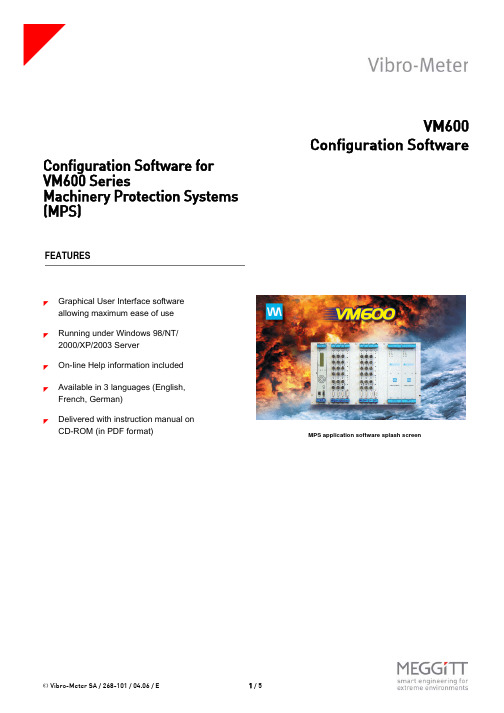
t © Vibro-Meter SA / 268-101 / 04.06 / E1 / 5VM600Configuration SoftwareConfiguration Software for VM600 SeriesMachinery Protection Systems (MPS)FEATURES]Graphical User Interface software allowing maximum ease of use ]Running under Windows 98/NT/2000/XP/2003 Server]On-line Help information included ]Available in 3 languages (English, French, German)]Delivered with instruction manual on CD-ROM (in PDF format)MPS application software splash screent d r a ft MPS1 & MPS2VM600 Configuration Software© Vibro-Meter SA / 268-101 / 04.06 / E 2 / 5DESCRIPTIONVibro-Meter has developed two configuration software packages for use with the VM600 series Machinery Protection Systems (MPS). The packages run under Windows 98/NT/2000/XP/2003 Server and are menu-driven for ease of use. MPS1 and MPS2 allow stand-alone configuration of MPC 4 and AMC 8 cards, via the cards’ serial connectors. Alternatively, if the cards are installed in a networked VM600 rack, i.e. one containing a modular CPU card (type CPU M) used for rack control and communication, they can be configured in "one-shot" mode using an Ethernet TCP/IP link from the PC to the CPU M.All major parameters concerning the speed and vibration channels processed by the cards can be configured. This includes the input of sensor characteristics, the choice of the type of vibration monitoring to perform, the definition ofmeasurement units, rectification types, alarm levels, etc.MPS2 is a configuration, visualization and trending package for MPC 4 and AMC 8 cards installed in a networked VM600 rack.It has the same configuration functionality as MPS1 plus additional data recording and display features. Data measured can be stored in a database and recalled later for trend analysis. Up to 50,000 data records can be stored using a cyclic ‘first-in-first-out’ method. The period of time that database records can cover depends on the data acquisition rate you have specified. These features let you display a number of different charts showing the real-time display of sensor values or alternatively, graphs for trend analysis. The following charts can be displayed :Configuration screen for a processing channelConfiguration screen for an MPC 4 cardr s t d r a f t © Vibro-Meter SA / 268-101 / 04.06 / E 3 / 5MPS1 & MPS2VM600 Configuration Software1.Bar chart (real-time values)Up to 8 bars can be displayed per page. Direct access to other pages available. Status of all bars on all pages can be seen at a glance.2.Strip chart (real-time values)Up to 16 lines can be displayed per page. Direct access to other pages available. Status of all lines on all pages can be seen at a glance. Zoom facilities and print function available.DESCRIPTION (Continued)Bar charts showing real-time display of monitored signals Strip charts showing real-time display of monitored signalst d r a ft MPS1 & MPS2VM600 Configuration Software© Vibro-Meter SA / 268-101 / 04.06 / E 4 / 53.Trend chart (historic values)Feature available for analysis of historic data acquired at the user’s request.Up to 16 lines can be displayed. Zoom facilities and print function available.4.Long-term (averages) trend chartUp to 16 lines can be displayed. Zoom facilities, print function and data export facilities availableDESCRIPTION (Continued)Short term trend chartLong term (averages) trend chart© Vibro-Meter SA / 268-101 / 04.06 / E 5/ 5MPS1 & MPS2VM600 Configuration SoftwareIn this publication, a dot (.) is used as the decimal separator and thousands are separated by spaces. Example : 12 345.678 90. Although care has been taken to assure the accuracy of the data presented in this publication, we do not assume liability for errors or omissions. We reserve the right to alter any part of this publication without prior notice.Sales officesYour local agentHead officeVibro-Meter has offices in more than 30 countries. For a complete list, please visit our website.Vibro-Meter SARte de Moncor 4P.O. BoxCH-1701 FribourgSwitzerland Tel: +41 26 407 11 11Fax: +41 26 407 13 01To order please specify :Note : “SSs” represents the firmware (embedded software) version.When ordering please also specify:Code 1 : 01=English, 02=French, 03=German (the language required)Code 2 : n=number of copies (how many paper copies of the user manual you require)Code 3: 00=MPC 1 not supported, 01=MPC1 supportedFor example: 209-500-100-SSs /01 /03/ 00 would request: MPS 1 software in English, with 3 user manuals and a MPC 1 card is not supported.HARDWARE REQUIREMENTSMinimum Computer Configuration•200 MHz, Pentium based personal computer •One 9-pin serial port •32 MByte memory•Ethernet port (TCP/IP)•200 MByte hard disk space free •Windows 98/NT/2000/XP/2003 Server •CD-ROM drive •VGA monitorPrinter•Any Windows compatible printerORDERING INFORMATIONTypeDesignationOrdering NumberMPS1Configuration Software for VM600 Protection System209-500-100-SSsMPS2Configuration and Trending Software for VM600 Protection System209-500-200-SSs。
PRIMERGY RX600 S2系统配置与订单信息指南说明书

System Configuration and order-information GuideRX600 S2October 2006®CD-ROM DriveHard Disk BaySystem FanDisplay 5 inch BaySerial Port Display 10/100/1000Base T ConnectorPCI SlotPower SupplyCPUMemory Expansionfront sideThis document contains basic product and configuration information that will enable you to configure your system.Only these tools will ensure a fast and proper configuration of your PRIMERGY server or your complete PRIMERGY Rack system.You can configure your individual PRIMERGY server in order to meet your specific requirements.Please follow the lines. If there is a junction, you can choose which way or component you would like to take.Go through the configurator by following the lines from the top to the bottom.The color of the junction means as follows.[Single-Core CPU models]4-Way Processor Rack ServerBase Unit PGUR6024APGUR6022APGUR6026ACPUFrequencies 64-bit Intel® Xeon® MP 3.66GHz64-bit Intel® Xeon® MP 3.16GHz64-bit Intel® Xeon® MP 3.33GHzSecond-Level-Cache 1MB 1MB Third-Level-Cache -8MBMulti-Processormax. 4 (2 for standard)Front-Side-Bus 667MHz Chipset Intel® E8500MemoryStandard 2GB (1GB ECC DDR2 SDRAM DIMM x 2)Maximum *132GB (2GB ECC DDR2 SDRAM DIMM x 16) when Memory Expansion Board (PG-RB105) is appliedGraphics Controller ATI Radeon 7000M, VRAM:16MB Resolution *2640x480/800x600/1024x768/1280x1024 dotInternal Bays Number of bays 5 (1" Height)3.5 inch Available HDD *373.4GB (PG-HDH71V) 10krpm, U320 SCSI HDD146.8GB (PG-HDH41V) 10krpm, U320 SCSI 300.0GB (PG-HDH31V) 10krpm, U320 SCSI 73.4GB (PG-HDH75V) 15krpm, U320 SCSI 146.8GB (PG-HDH45V) 15krpm, U320 SCSIStandard -Maximum *31.5TB (300.0GB x 5)5 inch Bay1CD-ROM/DVD-ROM CD-ROM (Max. 24 ATAPI): standard, DVD-ROM: optionalPCI SlotsPCI-X (64bit/100MHz) 2 (non hot plug)PCI-X (64bit/133MHz) 1 (hot plug)PCI-Express (x8) 1 (hot plug)PCI-Express (x4)3 (hot plug)RAID Controller onboard, 256MB Cache, BBUSCSI Controller Ultra320 SCSI x 2chFDDoptional *5Network Controller (onboard) 2 ports (1000 BASE-T/100 BASE-TX/10BASE-T)InterfacesDisplay x 2 (Analog RGB) *6, Serial Port (D-SUB 9pins) x 1,USB x 5(Front : x 3,Rear : x 2) (ver. 1.1) *5, *7Server Management Software ServerView (Standard)Power supplyVoltageAC 200VPower consumption 1100W / 3960kJ/h (max.)Redundant power supplystandard (1+1)Redundant Fanstandard (2+2)Dimensions (W x D x H (mm) )447 (482.6 incl. protruding parts )(W) x 706 (737 incl. protruding parts )(D) x 176 (4U) (H)Weight50kg (max.)Environmental Conditions Temperature10-35°C / Humidity 20-80% (non condensing)OS Support *4Windows Server 2003, Standard Edition / Windows Server 2003, Enterprise Edition Windows Server 2003, Standard x64 Edition / Windows Server 2003, Enterprise x64 EditionWindows® 2000 Server/Windows® 2000 Advanced ServerRed Hat Enterprise Linux AS (v.3 for x86)Red Hat Enterprise Linux AS (v.4 for x86) / Red Hat Enterprise Linux AS (v.4 for EM64T)Attached tool (Standard)ServerStart (Setup Support tool)*1. Available memory capacity will be changed by the type of OS. Please find more details in Notes[Memory OS Compatibility List].*2. Resolution is determined by functions of the display monitor and OS.*3. HDD capacity is calculated according to the formulas 1GB=10003 byte and 1TB=10004 byte.*4. Drivers for Linux are not attached. Please download and use drivers of the following URL./global/services/computing/server/ia/driver/*5: One USB-FDD is required as a minimum in multiple servers. It is necessary to procure USB-FDD separately.USB-FDD can be connected to base unit with USB extension cable attached as standard.*6: Front and rear display connectors cannot be used at the same time.The Front display connector cannot be used with Windows® 2000 Server or Windows® 2000 Advanced Server.*7: PS/2-keyboard and PS/2-mouse can be connected to base unit with USB-PS/2 conversion cable.TypeData Sheet[Dual-Core CPU model]Type4-Way Processor Rack ServerBase Unit PGUR6028ACPU Frequencies Dual Core Intel® Xeon® 7040 3GHzSecond-Level-Cache2x2MBThird-Level-Cache-Multi-Processor max. 4 (2 for standard)Front-Side-Bus667MHzChipset Intel® E8500Memory Standard2GB (1GB ECC DDR2 SDRAM DIMM x 2)Maximum *132GB (2GB ECC DDR2 SDRAM DIMM x 16) when Memory Expansion Board (PG-RB105) is applied Graphics Controller ATI Radeon 7000M, VRAM:16MBResolution *2640x480/800x600/1024x768/1280x1024 dotInternal Bays Number of bays 5 (1" Height)3.5 inch Available HDD *373.4GB (PG-HDH71V) 10krpm, U320 SCSIHDD146.8GB (PG-HDH41V) 10krpm, U320 SCSI300.0GB (PG-HDH31V) 10krpm, U320 SCSI73.4GB (PG-HDH75V) 15krpm, U320 SCSI146.8GB (PG-HDH45V) 15krpm, U320 SCSIStandard-Maximum *3 1.5TB (300.0GB x 5)5 inch Bay1CD-ROM/DVD-ROM CD-ROM (Max. 24 ATAPI): standard, DVD-ROM: optionalPCI Slots PCI-X (64bit/100MHz) 2 (non hot plug)PCI-X (64bit/133MHz) 1 (hot plug)PCI-Express (x8) 1 (hot plug)PCI-Express (x4) 3 (hot plug)RAID Controller onboard, 256MB Cache, BBUSCSI Controller Ultra320 SCSI x 2chFDD optional *5Network Controller (onboard) 2 ports (1000 BASE-T/100 BASE-TX/10BASE-T)Interfaces Display x 2 (Analog RGB) *6, Serial Port (D-SUB 9pins) x 1,USB x 5(Front : x 3,Rear : x 2) (ver. 1.1) *5, *7Server Management Software ServerView (Standard)Power supply Voltage AC 200VPower consumption1100W / 3960kJ/h (max.)Redundant power supply standard (1+1)Redundant Fan standard (2+2)Dimensions (W x D x H (mm) )447 (482.6 incl. protruding parts)(W) x 706 (737 incl. protruding parts)(D) x 176 (4U) (H) Weight50kg (max.)Environmental Conditions Temperature10-35°C / Humidity 20-80% (non condensing)OS Support *4Windows Server2003, Standard Edition / Windows Server2003, Enterprise EditionWindows Server2003, Standard x64 Edition / Windows Server2003, Enterprise x64 EditionRed Hat Enterprise Linux AS (v.3 for x86)Attached tool (Standard)ServerStart (Setup Support tool)*1. Available memory capacity will be changed by the type of OS. Please find more details in Notes[Memory OS Compatibility List].*2. Resolution is determined by functions of the display monitor and OS.*3. HDD capacity is calculated according to the formulas 1GB=10003 byte and 1TB=10004 byte.*4. Drivers for Linux are not attached. Please download and use drivers of the following URL./global/services/computing/server/ia/driver/*5: One USB-FDD is required as a minimum in multiple servers.It is necessary to procure USB-FDD separately.USB-FDD can be connected to base unit with USB extension cable attached as standard.*6: Front and rear display connectors cannot be used at the same time.The Front display connector cannot be used with Windows® 2000 Server or Windows® 2000 Advanced Server.*7: PS/2-keyboard and PS/2-mouse can be connected to base unit with USB-PS/2 conversion cable.*Components installed as standard configuration marked in grey.PCI PCI-XPCI PCI-XExpressExpressInternal/External SCSI ConnectorExternal array*1. The maximum number of LAN cards is 4.*2 In case that 2 RAID controller cards are mounted, the following pattern1 and pattern2 are available. ( pattern 3 is not available.)High Low -○○×3○○2○ ○1○○ pattern 267---slot mount priorityavailable/ not available133 (*1)23(*1)Remarks4Max No.of Mount44 (*1)-71-3----4456-Full Height43.3V3.3V x8socketPCI Slot Priority122 (*2) 3 (*2)1----PG-128PCI/64bit ----11-PCI/64bitMount PriorityPGB286PCIExpress (x4)PCIExpress (x4)Fibre Channel ControllerEth. Ctrl dual 1000-BASE-TRemote Service BoardPG-FC201PG-286PGBFC201RAID Ctrl 2-Channel 128MB w/BBUPG-RSB104PGBRSB104--2PGB128PG-142E3SCSI Ctrl U160PGB142E32-2-Bus3x8laneMountable CardsEth. Ctrl 1000-BASE-T CuEth. Ctrl 1000-BASE-SX Fibre LC -Eth. 2x 1000-BASE-T Cu-PGB1892PG-1892PCI-X/64bitPG-1882PG-1862--1---22364bit/133M Hz x4lane 64bit/100MHz321-x4socket3-3PCI-X/64bit PCI-X/64bit1--22(*1)-1HighLowHigh LowProcessor Xeon 7040 3.0GHz/2x2MB PG-FG30KPGBFG30K (for CTO/ for 1st additional CPU) PGBFG30K2 (for CTO / for 2nd additional CPU)*. This option is available when the processors of the base unit are Processor Xeon 7040 3.0GHz/2x2MB.Processor Xeon MP 3.33GHz/8MB PG-FG209PGBFG209 (for CTO/ for 1st additional CPU) PGBFG2092 (for CTO / for 2nd additional CPU)*. This option is available when the processors of the base unit are Processor Xeon MP 3.33GHz/8MB.Processor Xeon MP 3.66GHz/1MB PG-FG208PGBFG208 (for CTO/ for 1st additional CPU) PGBFG2082 (for CTO / for 2nd additional CPU)*. This option is available when the processors of the base unit are Processor Xeon MP 3.66GHz/1MB.Processor Xeon MP 3.16GHz/1MB PG-FG207PGBFG207 (for CTO/ for 1st additional CPU) PGBFG2072 (for CTO / for 2nd additional CPU)*. This option is available when the processors of the base unit are Processor Xeon MP 3.16GHz/1MB.Standard Memory BoardMemory Module-2GB (1GB DIMM x 2)PG-RM2BDPGBRM2BD (for CTO)Memory Expansion Board Memory Module-4GB (2GB DIMM x 2)PG-RM4BDPGBRM4BD (for CTO)Memory Module Conversion kit-4GB (2GB DIMM x 2)PGBRU4BD (for CTO)4GBMax: 3Memory Module-2GB (1GB DIMM x 2)PG-RM2BDMemory Module-4GB (2GB DIMM x 2)PG-RM4BD1. The installation order of Memory Expansion Board is as following.Memory Expansion Board A(standard) → Memory Expansion Board B → Memory Expansion Board C → Memory Expansion Board D 2. Two same capacity DIMM cards should be installed at a time.Two different capacity DIMM cards shouldn't be installed at a time. Only one DIMM card shouldn't be installed at a time.3. The installation order of Memory is as following.(1) [DIMM slot 1A,1B(Bank1)] → [DIMM slot 2A,2B(Bank2)](2) [Memory Module-2GB(1GB-DIMMx2)] → [Memory Module-4GB(2GB-DIMMx2)]4. Available Memory CapacitySame as the size of mounted memory (Note: "0.1-1.0GB" which is being used for PCI resource management Size of Mounted Memory minus "0.1-1.0GB"depends on the type and the number of installed memory modules.Mounted MemoryAvailable Memory Area2.0GB CPUdummy dummy CPU CPU dummy 4.0~32.0GBCPUCPUCPU23CPU CPU 4CPU1socket CPU2socket CPU3socket CPU4socket CPU the number of CPUs5. Spare Memory FunctionSpare Memory function assigns Spare Memory by Memory Expansion Board.(1) Memory capacity of Bank1 and Bank2 should be same.(2) Spare Memory structure should be made on all installed Memory Expansion Board.(3) If spare Memory function is applied, Memory mirroring function and Memory RAID function cannot be applied.(4) Available memory capacity is the half of installed memory.The Memory installation for Spare Memory function is as following.0 : Memory is installed.- : Memory is not installed.6. Memory Mirroring FunctionMemory Mirroring function assigns mirror set by 2 Memory Expansion Board.(1) Memory capacity of 2 Memory Expansion Board of mirror set should be same.(2) The structure of mirror set is as following.- When 2 Memory Expansion Board are installed : mirror set #1 (Memory Expansion Board A + Memory Expansion Board B)- When 4 Memory Expansion Board are installed : mirror set #1 (Memory Expansion Board A + Memory Expansion Board B)mirror set #2 (Memory Expansion Board C + Memory Expansion Board D)(3) If Memory mirroring function is applied, spare Memory function and Memory RAID function cannot be applied.(4) Available memory capacity is the half of installed memory.The Memory installation for Memory Mirroring function is as following.0 : Memory is installed.- : Memory is not installed.7. Memory RAID FunctionMemory RAID function assigns Memory RAID by 4 Memory Expansion Board.(1) Memory capacity of all Memory Expansion Board should be same.(2) If Memory RAID function is applied, spare Memory function and Memory mirroring function cannot be applied.(3) Available memory capacity is three quarters of installed memory.The Memory installation for Memory RAID function is as following.0 : Memory is installed.- : Memory is not installed.8. Hot Plug FunctionIf Memory mirroring function or Memory RAID function is applied, hot plug function of Memory Expansion Board is available.Memory Expansion Board B Memory Expansion Board CMemory Expansion Board D Bank21A 1B 2A 2B 1A 1B 2A 2B 1A Bank1Bank2Bank1Bank21A 1B 2B 002A 00Bank1Bank2Bank100Memory Expansion Board A 0000000000Memory Expansion Board A Memory Expansion Board B Bank1Bank2Bank1Bank21A 1B 2A 2B ----00000000000Memory Expansion Board C Bank1Bank21A 1B 2A 2B --------0000000Memory Expansion Board D Bank1Bank21A 1B 2A 2B ------------0001B 2A 2B 1A 1B 2A 2B 00--00----------00--00--00--00--0000000-0------000000000mirror set #1mirror set #200-0Memory Expansion Board A Memory Expansion Board B Memory Expansion Board C Memory Expansion Board D Bank1Bank2Bank1Bank2Bank1Bank2Bank1Bank21A 1B 2A 2B 1A 1B 2A 2B 1A 1B 2A 2B 1A 1B 2A 2B 00--00--00--00--000000000(''1) Wide Backup Devices: PG-DT501/PG-VX201(''2) Narrow Backup Devices: None(''3) Wide Backup Devices: PG-DT501/PG-LT201/PGBLT201/PG-VX201(''4) Backup Devices which occupies 2 bays: NoneTape Drv DAT72 36GB internal PG-DT501SCSI Cable 1.0m PGBDT501 (for CTO)Tape Drv LTO2 Ultrium2 200GB PG-LT201PGBLT201 (for CTO)Tape Drv VXA-2 80GB PG-VX201HDD HDDSCSI Cable HDCI 1.5mRemote Service Board Twist Pair CablePG-RSB104PGBRSB104 (for CTO)Specifications are subject to change without notice. For the latest detailed information, contact your local representative. All brand names and product names are trademarks and registered trademarks of their respective holders.©2006 Fujitsu Limited. All rights reserved. Printed in Japan.Global Business Development & MarketingBusiness Strategy & PlanningSystem ProductsURL 。
华为电源柜 用户手册

前言
前言
概述
本文档提供了直流电源系统的产品介绍、部件介绍和系统维护。 本文档中的图片仅供参考,具体结构以实物为准。
读者对象
本文档(本指南)主要适用于以下工程师: 销售工程师 技术支持工程师 维护工程师
符号约定
在本文中可能出现下列标志,它们所代表的含义如下。
符号
说明
用于警示紧急的危险情形,若不避免,将会导致人员死亡或严重 的人身伤害。
华为专有和保密信息
iii
版权所有 © 华为技术有限公司
TP48600T-N20A3 用户手册
目录
目录
前 言................................................................................................................................................. ii
4 系统维护........................................................................................................................................27
4.1 例行维护 ................................................................................................................................................................... 27 4.2 告警处理 ................................................................................................................................................................... 28 4.2.1 交流停电 ................................................................................................................................................................ 28 4.2.2 交流过压 ................................................................................................................................................................ 28 4.2.3 交流欠压 ................................................................................................................................................................ 28 4.2.4 交流 A/B/C/缺相.................................................................................................................................................... 29 4.2.5 直流过压 ................................................................................................................................................................ 29 4.2.6 直流欠压 ................................................................................................................................................................ 29 4.2.7 LLVD 下电 .............................................................................................................................................................. 30 4.2.8 BLVD 下电.............................................................................................................................................................. 30
旗滨东山600t冷端线控系统操作说明书.
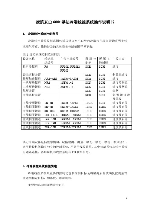
旗滨东山600t浮法冷端线控系统操作说明书1. 冷端线控系统控制范围冷端线控系统控制范围包括从退火窑出口处的冷端拉引辊道开始直到主线末端气浮桌。
线控涉及的具体设备控制范围详见下表:其它冷端设备包括紧急横切,缺陷检测、测量、纵切、横切、喷粉、吹风清扫、水平堆垛机等均有独立的控制系统,不属于线控系统。
其中切割系统与线控系统有通讯连接;各堆垛机与线控系统有I/O联络信号。
2. 冷端线控系统功能简述冷端线控系统最重要的控制功能和控制目标是将横掰后的玻璃板按质量等级送到指定目标,如落板、堆垛机等。
主要控制功能简要描述如下:线控系统的控制程序就是模拟生产线的实际运行状态,以辊道运行速度、玻璃行走距离、玻璃板长度、玻璃质量等级为主要参数,形成全线玻璃信息队列。
并由此实现玻璃全线自动跟踪控制。
每片玻璃在横掰后,将包含了板规格、玻璃等级信息的玻璃板加入到玻璃队列,并开始以辊道的运行速度计算其在生产线的位置,直到玻璃落板、堆垛、或走出主线进入到气浮桌为止。
各玻璃运行到各特定的位置上将触发不同的控制输出信号,如加速辊道的变速控制,掰边、纵掰电磁阀动作控制,落板装置动作控制,堆垛辊道减速、爬行定位及堆垛控制,辊道联锁停车定位控制等等。
其中,玻璃板规格数据由切割系统通讯传来。
玻璃等级信息通过缺陷检测及打标信号提供。
辊道速度由人工设定或由线控系统根据退火速度自动计算。
整个玻璃队列的移动只受辊道运行状态和运行速度影响。
生产线上的光电开关主要用于玻璃位置的实际校验。
综上所述,线控系统的核心是玻璃队列的模拟控制,其关键点主要是二个:横掰位置的准确控制:即横掰辊抬起并掰断玻璃的重复位置要求较高,否则进入玻璃队列的初始位置偏差会变大,不利于后续的跟踪控制。
横掰位置的调节是在切割系统上操作的,需要相关操作人员注意。
同时横掰汽缸的气压应保持相对稳定。
辊道的运行状态要准确,包括辊道运行状态信号的反馈要准确,辊道变频器、伺服驱动器中与速度、加减速相关的参数值必须按供货商的要求进行准确设置,不得随意变更。
TR600 使用说明书
TR600数字式应变电阻传感器变送器使用说明书LONGTEC 珠海市长陆工业自动控制系统有限公司用前须知:u初次使用前,请详细阅读本说明书,现场使用许多疑难问题,在本说明书中将找到答案。
u使用前,请检查称重系统其他部件是否匹配。
u使用本仪表,注意防晒、防雨水、防撞击。
u使用本仪表,请尽可能配备常用安装、检修工具:小型一字螺丝刀,数字式万用表,称重传感器模拟器(mV信号发生器)。
目录用前须知: (1)1概述 (5)1-1简介 (5)1-2有关术语 (5)1-3特点 (5)2技术参数 (6)2-1一般参数 (6)2-2数字部分 (6)2-3模拟部分 (6)3安装 (7)3-1安装注意事项 (7)3-2变送器输入灵敏度 (7)3-3传感器与变送器之连接法 (8)3-4变送器最长可联接的称重信号电缆长度表 (8)3-5称重传感器接线方式 (8)3-6安装尺寸图(单位:MM) (8)4显示面板及按键说明 (9)4-1前面板及打开保护盖示意图 (9)4-2保护盖 (9)4-3接线端子说明 (10)4-4数码显示说明 (10)4-5在称重状态下各功能键的说明 (10)4-6波特率选择说明 (10)4-7ID地址选择说明 (10)5功能设置 (11)5-1参数设定 (11)5-1-1“FUNC”进入设定 (11)5-1-2“F10”零位跟踪时间 (12)5-1-3“F20”动态检测范围 (12)5-1-4“F30”RS232/485通讯输出速率 (12)5-1-5“F40”小数点选择 (13)5-1-6“F50”分度间距 (13)5-1-7“F6 0”最大量程 (13)5-1-8“F70”数字滤波 (14)5-2经由RS232/RS485接口设定功能(配RS232或RS485有此功能) (15)5-2-1零位跟踪范围 (15)5-2-2动态检测范围 (15)5-2-3RS232/RS485通讯输出速率 (15)5-2-4小数点 (15)5-2-5分度间距 (16)5-2-6最大量程 (16)5-2-7数字滤波 (16)6.仪表标定 (16)6-1标定的意义 (16)6-2操作 (17)6-2-1零位标定 (18)6-2-2秤量间距标定 (18)6-2-3标定错误提示 (19)6-3经由RS232/RS485接口标定(配RS232或RS485有此功能) (20)6-3-1 TR600可经由RS232/RS485接口直接调校 (20)7.称重定值比较量设置按键操作: (21)7-1设置参数步骤 (21)7-2经由RS232/RS485设定比较值(配RS232或RS485有此功能) (23)8.通讯参数的设定 (23)8-1通讯格式说明 (23)8-2波特率的设定 (25)8-3通讯ID地址的设定 (25)9.输入/输出 (25)9-1控制输入 (25)9-1-1输入接口(内置) (25)9-1-2输入接口与外接开关的联接 (26)9-1-3输入接口与PLC的联接......................................................................................错误!未定义书签。
LT-600使用手册

视频输入:1V p-p视频信号
接线芯数:8芯超五类网线
视频阻抗:75欧
外形尺寸:230*160*22mm
主要功能:
四防区及密码布防、现场报警与管理中心报警、访客二次确认等功能。四防区分别为:烟感、瓦斯、红外、门磁。豪华型设计,铃声、对比度、亮度可调节。
免提通话
门口机呼叫通话并显示访客影像
智能化楼宇对讲系统
智能化楼宇对讲系统
使用手册
深圳市中联泰电子有限公司
SHEN ZHEN CHINALOGIC TECHNOLOGY CO.,LTD.
前言
欢迎您成为中联泰大家庭的一员。
我们非常高兴您选择了中联泰智能化楼宇对讲系统。
在使用CLT产品前,请您仔细阅读本《使用手册》,并妥善保管,以便备用。
联网接口:RS-485
面板尺寸:328X230(mm)
后壳尺寸:313X213X45(mm)
三、LT-W600围墙机
※主要功能:
可呼叫小区内任一单元住户及管理中心。高亮度数码管显示、密码或增加门禁开锁、呼叫用户遥控开锁、时间显示。
※技术参数:
通话时间:≤3分钟
输入电压:DC18V,由LT-SP供给
联网接口:RS-485
例二:需设置单元门牌为8号的门口主机。按上述流程操作,待操作显示“ ”时,在键盘上输入“008”三位数字,主机显示“ ”字样,表示操作成功。
2.修改房号操作流程为:按“*”键两次,门口主机显示“ ”,此时输入13283388,门口机显示“ ”,此时按一次“3”键,门口机显示“ ”,在显示“ ”时,接着按一次“*”键,
显示“ ”连按“*”键,数码管会不断显示不同的解码器端口及房号。
在显示解码器及端口号的状态时,可直接找出所需要的第几号解码器的第几号端口号。例如:在操作至显示“01J1”时,需直接找出05号解码器的第一个端口进行房号修改,在键盘上输入“051”三位数,门口机显示“05J1”,此时按“*”键一次,显示房号“0501”,此时,可进行房号修改,在键盘上输入新的房号(实际用的房号),输入后门口机会自动显示下一个端口号“05J2”,此时按“*”键一次,显示房号“0502”,此时,可进行房号修改。依次类推,可一次性快速将房号修改完成,修改好的解码器端口插上室内机,在门口机键盘上输入新的房号进行呼叫,呼通后室内机可对讲及遥控开锁。
600系列报警主机说明书
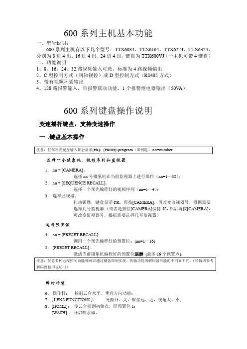
600系列主机基本功能一、型号说明:600系列主机有以下几个型号:TTX6084、TTX6164、TTX6224、TTX6324,分别为8进4出、16进4出、24进4出,键盘为TTX600VJ (一主机可带4键盘)二、功能说明1、8、16、24、32路视频输入可选,标准为4路视频输出2、C 型控制方式(同轴视控)或D 型控制方式(RS485方式)3、带有视频环通输出4、128路报警输入,带报警联动功能,1个报警继电器输出(50V A )600系列键盘操作说明变速摇杆键盘,支持变速操作一 .键盘基本操作选择一个摄象机、视频序列和监视器1. nn + [CAMERA]:选择nn 号摄象机在当前监视器上进行操作(nn=1—32);2. nn + [SEQUENCE RECALL];选择一个预先编程好的视频序列(nn=1—4);3. 选择监视器:扭动钥匙,键盘显示PR ,再按[CAMERA],可改变监视器号,根据需要选择几号监视器;(或者是按住[CAMERA]保持5S ,然后再按[CAMERA],可改变监视器号,根据需要选择几号监视器)选择预置位4. nn + [PRESET RECALL]:调用一个预先编程好的预置位;(nn=1—16)5. [PRESET RECALL]:瞬时功能6. 操作杆: 控制云台水平、垂直方向功能;7.[LENS FUNCTIONS ]: 光圈开、关,聚焦远、近,视角大、小;8.[HOME]: 使云台回到初始点,即预置位1;[WASH]: 开启喷水器,[AUX2]:使用直流云台时,会使其速度加倍。
开关控制功能键[LENS SLOW]、[AUTO IRIS]、[LAMPS]、[CAMARA ON/OFF]、[WIPE]、[AUX1]分别为镜头慢速,自动光圈,灯光,摄象机开关,雨刮器,辅助功能键(以上各功能要求设备具有相应的功能才能实现)。
[ALL ON]、[ALL OFF]全开和全关功能,例如:[ALL ON] [WIPE]就是将所有的雨刷器都打开。
WISE PT600 安装设置手册

PT600安装设置手册PT600控制系统安装设置手册目录目录第一部分系统介绍简介4技术参数4典型应用4设备及配件装箱清单5端口说明6第二部分系统设置系统设置向导软件的安装7系统设置连接8确定设置用串口8选择设置方式9选择被控制设备的控制方式10选择被控制设备型号11RS232串口通信参数设置12被控制设备红外码类别识别13PT600面板按键功能设置14 PT600柜门探测功能设置15系统功能维护16增加功能17被控制设备RS232串口控制指令码设置18被控制设备红外码学习19延时时间设置20组合功能设置21最后一步22设置报告查看22保存设置22数据传输22第三部分设备连接PT600控制系统安装设置手册目录面板与主机连接示意图23 UPS系统连接示意图24投影机、门探连接示意图25计算机信号连接示意图26电动屏幕连接27第四部分技术支持常见故障及解决方法28技术支持途径29第五部分附录PT600面板安装尺寸30技术参数31编程电缆引脚定义32投影机控制接线图32系统功能表33 PT600控制系统安装设置手册第部分系统介绍第一部分系统介绍简介PT600控制系统是专为多媒体投影机设计的一套控制系统。
它与WISE DP700一样具有安装方便、操作简易、高度的稳定可靠、故障率极低等特点。
在功能上作了更进步的简化在信号切换上依靠投影机本身所带端口主要应用在些控制功能要求一步的简化,在信号切换上依靠投影机本身所带端口,主要应用在一些控制功能要求简单的多媒体教室建设中。
主要技术参数1.一路RS232/IR控制接口(复用)2.一路AC220V电源可控制输出(用于投影机供电,延时时间可设定)两路开关量信号探测口3.两路开关量信号探测口(UPS和门锁)4.四键式按键面板(键功能可自由设置)5.一路电动屏幕控制端口6.一路VGA信号输入,两路输出7.一路UPS开关控制端口8.两路电源输入(UPS和市电)典型应用一台具备VIDEO端口和RGB端口的投影机、一台PC机、一台视频展示台-4-PT600控制系统安装设置手册系统设置连接步骤:1、确认PT600主机开关处于OFF 状态。
HAT600P_600PB_600PI_600PBI_600PS 中文说明书

HAT600P系列(HAT600P/HAT600PB/HAT600PI/HAT600PBI/HAT600PS)双电源自动切换控制器用户手册目次前言 (4)1概述 (6)2命名规范及型号对比 (7)2.1命名规范 (7)2.2型号对比 (7)3性能特点 (8)4规格 (9)5测量和显示数据 (11)6操作 (12)6.1指示灯描述 (12)6.2按键功能描述 (13)7屏幕显示 (14)7.1主显示 (14)7.2状态描述 (15)7.3主菜单 (19)8发电机组开停机操作 (20)8.1手动模式开停机 (20)8.1.1面板开停机 (20)8.1.2通讯遥控开停机 (20)8.2自动模式开停机 (20)8.2.1开机条件 (20)8.2.2两组发电机开停机 (21)8.2.3定时巡检开机 (22)8.2.4定时不开机 (22)9参数设置 (23)9.1说明 (23)9.2参数配置表 (23)9.3开关量输入口功能描述 (31)9.4开关量输出口功能描述 (32)9.5自定义组合输出 (34)9.6过流定时限与反时限设置 (35)10历史记录 (36)11黑匣子记录 (37)12谐波分析 (39)13开关操作运行 (40)13.1手动操作运行 (40)13.2自动操作运行 (40)13.2.1自投自复 (40)13.2.2自投不自复(互为备用有效) (41)13.2.3自投不自复(互为备用无效) (41)13.3同步合闸 (42)13.3.1S1同步合闸 (43)13.3.2S2同步合闸 (43)13.3.3手动同步合闸 (44)13.3.4自动同步合闸 (44)14ATS供电电源 (45)14.1直流供电 (45)14.2交流供电 (45)15非重要负载NEL控制 (47)15.1说明 (47)15.2自动操作 (47)15.3手动操作 (47)16通信配置及连接 (48)16.1说明 (48)16.2RS485通信口 (48)16.3USB通信口 (48)16.4ETHERNET通信口 (48)17端口定义 (50)17.1控制器端口描述 (50)17.2控制器供电说明 (52)17.2.1直流供电 (52)17.2.2交流供电 (52)17.3RS485连接说明 (52)18典型应用图 (54)19安装尺寸 (60)20故障排除 (61)前言表1 版本发展历史表2 本文档所用符号说明符号说明该图标提示或提醒操作员正确操作。
YT送丝机使用说明书

YT送丝机使用说明书成都振中电焊机厂邮政编码:厂址:成都外东西河镇南街105号电话:传真:首先感谢您购买本厂产品,从此您将同时拥有本厂优质的产品和优质的服务!为了正确和安全使用设备,使用前请仔细阅读使用说明书,如有疑问,请联系本厂技术支持部门。
目录1、产品描述 (2)2、技术参数 (3)3、安装 (4)4、操作 (4)5、维护 (5)6、故障及处理 (5)7、零部件清单 (7)8、随机文件 (11)9、附图(附后) (11)1、产品描述YT送丝机是埋弧焊专用送丝机构,适合直径范围为φ2.4~φ6的焊丝的送给。
配合MZ悬挂式控制器和ZX5或ZD5L弧焊整流器可以在龙门或悬臂焊接机上实现自动埋弧焊接。
订货时需注明送丝机是正向还是反向。
1.1、产品特点□采用方箱齿轮减速器。
□压丝弹簧行程大,焊丝压紧力调节范围大。
□电机和送丝机构绝缘,保证良好的电气绝缘性能。
□送丝轮两斜面均有齿,其中一面磨损后换一面可继续使用。
□送丝机可分正反成对使用。
1.2、外观图一YT送丝机(正)外观图YT送丝机(正)图示说明:1—L板(正);2—弯柄(正);3—铰链轴;4—轴承;5—固定块(正);6—螺套;7—弹簧;8—拉杆;9—滑块;10—校丝轮;11—支座;12—减速电机;13—送丝轮。
图二YT送丝机(反)外观图YT送丝机(反)图示说明:1—L板(反);2—弯柄(反);3—铰链轴;4—轴承;5—固定块(反);6—螺套;7—弹簧;8—拉杆;9—滑块;10—校丝轮;11—支座;12—减速电机;13—送丝轮。
2、技术参数(1)电机额定电压:110VDC(2)电机最大电流:≤2.1A(3)功率:165W(4)额定转速:20 rmp(5)最大送丝速度:3m/min(6)焊丝直径范围:φ2.4~φ6mm(7)外形尺寸:278×154×188(8)安装尺寸:4-M10螺孔,孔距110×25(9)重量:3、安装3.1、环境(1)环境温度:贮存时,-25℃~55℃运行时,-10℃~40℃(2)空气相对湿度:在40℃时,≤50%在20℃时,≤90%(3)使用场合应无严重影响运行的灰尘、酸碱、腐蚀性介质和易燃易爆物质。
绎泰yt600变频器说明书

绎泰yt600变频器说明书绎泰YT600变频器说明书一、引言绎泰YT600变频器是一种高性能的电气设备,广泛应用于工业生产中。
本说明书旨在介绍YT600变频器的特点、使用方法、维护保养以及常见问题的解决方法,以帮助用户正确使用和维护该设备。
二、特点1. 高性能:YT600变频器采用先进的变频技术,具有高效、稳定的性能,可满足各类工业生产的需求。
2. 变频范围广:YT600变频器可灵活调节电机的转速,变频范围广,使得设备能够适应不同工况的要求。
3. 节能高效:通过变频控制,YT600变频器能够对电机进行精细调节,以减少能耗,提高生产效率。
4. 控制精度高:YT600变频器具有精确的控制能力,可实现精细的运行控制,提高生产质量和稳定性。
三、使用方法1. 安装:将YT600变频器正确安装在控制柜中,并连接各个电气元件,确保接线正确可靠。
2. 参数设置:根据实际需求,通过面板上的按键或者通信接口,设置YT600变频器的工作参数,包括电机额定功率、额定电流、变频范围等。
3. 运行控制:根据需要,设置YT600变频器的运行模式,如手动控制、自动控制、远程控制等,并进行相应的启停、转速调节等操作。
4. 故障诊断:YT600变频器配备了故障诊断功能,当设备出现故障时,可通过面板显示屏上的故障代码,快速定位和解决问题。
四、维护保养1. 清洁:定期清洁YT600变频器的外壳和散热器,确保散热效果良好,避免灰尘积累影响设备正常运行。
2. 检查:定期检查YT600变频器的接线是否松动、腐蚀,以及散热器是否堵塞,保证设备的正常运行。
3. 润滑:对于带有轴承的部件,定期添加适量的润滑油或脂,以减少摩擦,延长设备使用寿命。
4. 保护:YT600变频器应妥善保护,避免水、尘埃等外界物质进入设备内部,造成故障或损坏。
五、常见问题解决方法1. 变频器无法启动:检查供电电源是否正常;检查控制信号是否正确;检查保险丝是否熔断。
2. 变频器显示异常:检查面板显示屏是否损坏;检查控制板是否正常工作。
YT-CM6016-G-G16 变电站网络交换机使用说明书
YT-CM6016-G-G16变电站网络交换机使用说明书深圳市源拓光电技术有限公司(以下简称“源拓光电”)为客户提供全方位的技术支持和服务。
直接向源拓光电购买产品的用户,如果在使用过程中有任何问题,可与源拓光电各地办事处或用户服务中心联系,也可直接与公司总部联系。
读者如有任何关于源拓光电产品的问题,或者有意进一步了解公司其他相关产品,可通过下列方式与我们联系:公司网址:技术支持热线:(0755)26641737技术支持传真:(0755)26640197技术支持邮箱:market@技术文档邮箱:market@客户投诉热线:(0755)26641737公司总部地址:深圳市宝安区石岩街道石龙仔社区森海诺科创大厦11-12楼邮政编码:528109―――――――――――――――――――――――――――――――――――――――――――――声明©copyright2016by Shenzhen Wintop Optical Technology Co.,Ltd.All rights reserved.源拓光电科技发展股份有限公司版权所有,保留一切权利。
非经本公司书面许可,任何单位和个人不得擅自摘抄、复制本书内容的部分或全部,并不得以任何形式传播。
是源拓光电科技发展股份有限公司的注册商标。
对于本手册中出现的其它商标,由各自的所有人拥有。
由于产品版本升级或其它原因,本手册内容会不定期进行更新。
除非另有约定,本手册仅作为使用指导,本手册中的所有陈述、信息和建议不构成任何明示或暗示的担保目录1概述 (6)2维护界面登录 (6)3产品信息 (6)4管理IP设置 (7)4.1IP地址简介 (7)4.2管理IP地址维护界面 (8)5用户管理 (8)6端口 (9)6.1端口设置 (9)6.2光口千百兆设置 (10)6.3端口限速 (11)6.4镜像配置 (11)6.5光模块信息 (12)6.6端口统计 (13)6.7静态单播MAC地址表 (14)6.8TRUNK (14)7VLAN配置 (15)7.1VLAN概述 (15)7.2VLAN的成员配置 (15)7.3VLAN的端口配置 (16)8QoS (16)8.1QoS概述 (16)8.2常用优先级介绍 (16)8.3队列调度介绍 (17)8.4QoS模式设置界面 (17)8.5端口优先级 (18)8.6Cos映射界面 (18)8.7Dscp映射界面 (19)8.8QoS端口信任模式界面 (19)9STP (19)9.1生成树简介 (19)9.2spanning tree设置 (20)9.3spanning tree端口 (20)9.4spanning tree信息 (21)10LLDP (22)10.2LLDP设置 (22)10.3LLDP端口 (22)10.4LLDP信息 (23)10.5LLDP统计 (23)11恢复出厂设置 (24)12配置文件管理 (25)1361850配置文件管理 (25)14保存重启 (26)15退出 (26)16静态组播MAC地址 (27)17GMRP功能配置 (27)17.1GMRP定义 (27)17.2GMRP维护界面 (27)18IGMP snooping设置 (28)18.1IGMP原理 (28)18.2IGMP设置 (28)18.3IGMP路由端口 (29)18.4IGMP统计 (29)18.5IGMP组 (30)19组播流量限速 (31)20VLAN组播选项 (31)21Dos攻击防御 (31)22告警管理 (32)22.1简介 (32)22.2安全设置 (32)23风暴抑制 (32)24端口MAC地址绑定 (33)25端口MAC地址学习限制 (33)26VLAN MAC地址学习限制 (34)27非法访问控制 (34)28SV报文延时累加 (35)29SV报文限速 (35)30GOOSE报文限速 (36)31电力报文优先级设置 (36)32SNTP及系统时间 (37)32.1SNTP简介 (37)33SNMP设置 (38)33.1SNMP简介 (38)33.2SNMP视图 (38)33.3SNMP团体 (38)33.4SNMP群组 (39)33.5SNMP用户 (39)33.6SNMP主机 (40)34日志管理 (40)34.1日志主机设置 (40)34.2系统日志 (41)34.3告警日志 (41)1概述YT-CM6016-G-G16维护界面手册用于指导设备调试人员应如何正确通过维护界面配置需要的功能。
Dell PowerVault 600 系统 硬件用户手册说明书

Dell™ PowerVault™ 600系统硬件用户手册注、注意和警告注:“注”表示可以帮助您更好地使用计算机的重要信息。
注意:“注意”表示可能会损坏硬件或导致数据丢失,并告诉您如何避免此类问题。
警告:“警告”表示可能会导致财产损失、人身伤害甚至死亡。
____________________本说明文件中的信息如有更改,恕不另行通知。
©2007Dell Inc.。
版权所有,翻印必究。
未经 Dell Inc.书面许可,严禁以任何形式进行复制。
本文中使用的商标:Dell、DELL徽标、Inspiron、Dell Precision、Dimension、OptiPlex、Latitude、PowerEdge、PowerVault、PowerApp、PowerConnect、XPS和Dell OpenManage 是 Dell Inc. 的商标;Intel是 Intel Corporation 的注册商标;Microsoft、Windows和MS-DOS是Microsoft Corporation 在美国和/或其它国家/地区的商标或注册商标;EMC是 EMC Corporation 的注册商标。
本说明文件中述及的其它商标和产品名称是指拥有相应商标和产品名称的公司或其制造的产品。
Dell Inc. 对其它公司的商标和产品名称不拥有任何所有权。
2009 年 9 月P/N NN712Rev. A01目录1关于系统 (11)放置方式 (12)您可能需要的其它信息 (12)在系统启动过程中访问系统配置 (13)前面板部件和指示灯 (14)硬盘驱动器指示灯代码 (16)背面板部件和指示灯 (19)连接外部设备 (20)电源指示灯代码 (20)NIC 指示灯代码 (21)LCD 状态信息 (22)解决 LCD 状态信息描述的问题 (30)删除 LCD 状态信息 (30)系统信息 (30)警告信息 (42)诊断程序信息 (43)警报信息 (43)目录32使用系统设置程序 (45)进入系统设置程序 (45)响应错误信息 (45)使用系统设置程序 (46)系统设置程序选项 (47)主屏幕 (47)“CPU Information”(CPU 信息)屏幕 (49)“Integrated Devices”(集成设备)屏幕 (51)串行通信屏幕 (53)“System Security”(系统安全保护)屏幕 (53)“Exit”(退出)屏幕 (55)系统密码和设置密码功能 (55)使用系统密码 (55)使用设置密码 (58)禁用已忘记的密码 (59)底板管理控制器配置 (59)进入 BMC 设置模块 (60)“BMC Setup Module”(BMC 设置模块)选项 (60)3安装系统组件 (61)建议使用的工具 (61)打开与装上主机盖和挡板(如果有) (62)卸下挡板 (62)卸下外围设备托架面板(仅适用于塔式) (64)安装外围设备托架面板(仅适用于塔式) (65)安装挡板 (65)打开主机盖 (65)合上主机盖 (65)4目录热插拔硬盘驱动器 (67)开始之前 (68)卸下驱动器挡片 (68)安装驱动器挡片 (68)卸下热插拔硬盘驱动器 (69)安装热插拔硬盘驱动器 (69)更换硬盘驱动器托盘 (71)从驱动器托盘中卸下硬盘驱动器 (71)将 SAS 硬盘驱动器安装到 SATAu 驱动器托盘中 (71)将 SATA 硬盘驱动器安装到 SATA 驱动器托盘中 (73)将 SATA 硬盘驱动器和插入器卡安装到 SATAu硬盘驱动器托盘中 (74)电源设备 (76)卸下电源设备 (76)安装电源设备 (77)卸下电源设备挡片 (78)安装电源设备挡片 (78)风扇 (78)卸下和安装风扇 (79)卸下或安装冷却导流罩风扇 (80)扩充卡 (82)安装扩充卡 (83)卸下扩充卡 (85)内部 SCSI 磁带备份装置 (85)卸下内部 SCSI 磁带备份装置 (85)安装内部 SCSI 磁带备份装置 (86)光盘驱动器 (88)卸下光盘驱动器 (88)目录5安装光盘驱动器 (89)软盘驱动器 (90)卸下软盘驱动器 (90)将软盘驱动器安装到驱动器托盘中 (92)安装软盘驱动器 (92)系统电池 (93)更换系统电池 (93)冷却导流罩 (95)卸下冷却导流罩 (95)安装冷却导流罩 (97)风扇支架 (97)卸下中央风扇支架 (97)装回中央风扇支架 (97)卸下后部风扇支架 (98)装回后部风扇支架 (98)内存 (98)一般内存模块安装原则 (101)非优化的内存配置 (101)内存备用支持 (101)内存镜像支持 (102)安装内存模块 (102)卸下内存模块 (104)RAC 卡 (105)卸下 RAC 卡 (105)安装 RAC 卡 (105)启用集成 NIC TOE (107)微处理器 (107)更换处理器 (108)6目录1x8 SAS 背板 (112)卸下 1x8 SAS 背板 (112)安装 1x8 SAS 背板 (112)可选 1x2 可更换托架驱动器支架 (113)卸下 1x2 可更换托架驱动器支架 (113)安装 1x2 可更换托架驱动器支架 (114)SAS 控制器子卡 (115)更换 SAS RAID 控制器子卡电池 (115)卸下 SAS 控制器子卡 (116)安装 SAS 控制器子卡 (118)SAS 背板的布线 (118)电缆要求 (118)(非 RAID)SAS 控制器的布线 (119)SAS RAID 控制器的布线 (119)配置引导驱动器 (122)控制面板部件(仅提供服务步骤) (122)卸下控制面板部件 (122)安装控制面板部件 (123)系统板(仅提供服务步骤) (124)卸下系统板 (124)安装系统板 (126)配电板(仅维修过程) (127)卸下配电板 (127)安装配电板 (129)4排除系统故障 (131)安全第一 — 为您和您的系统着想 (131)目录7启动例行程序 (131)检查设备 (132)排除 IRQ 分配冲突故障 (132)排除外部连接故障 (133)排除视频子系统故障 (133)排除键盘故障 (134)排除鼠标故障 (134)排除基本 I/O 功能故障 (135)排除串行 I/O 设备故障 (135)排除 USB 设备故障 (136)排除 NIC 故障 (137)排除受潮系统故障 (137)排除受损系统故障 (138)排除系统电池故障 (139)排除电源设备故障 (140)排除系统冷却故障 (141)排除风扇故障 (141)排除系统内存故障 (142)排除软盘驱动器故障 (144)排除光盘驱动器故障 (145)排除外部 SCSI 磁带驱动器的故障 (146)排除硬盘驱动器故障 (147)排除 SAS 或 SAS RAID 控制器子卡故障 (148)排除扩充卡故障 (150)8目录排除微处理器故障 (151)5运行系统诊断程序 (153)使用服务器管理员诊断程序 (153)系统诊断程序功能 (153)何时使用系统诊断程序 (154)运行系统诊断程序 (154)系统诊断程序检测选项 (154)使用自定义检测选项 (155)选择要检测的设备 (155)选择诊断程序选项 (155)查看信息和结果 (155)6跳线和连接器 (157)系统板跳线 (157)系统板连接器 (159)SAS 背板连接器 (161)禁用已忘记的密码 (162)7获得帮助 (165)技术帮助 (165)联机服务 (165)自动技术支持服务 (166)订单状态自动查询服务 (167)目录9技术支持服务 (167)Dell 企业培训与认证 (167)订单相关问题 (167)产品信息 (167)退回物品以要求保修或退款 (167)致电之前 (170)与 Dell 联络 (170)词汇表 . . . . . . . . . . . . . . . . . . . . . . . . . . . . .191索引 (203)10目录1关于系统本节介绍了物理、固件和软件接口部件,它们提供了系统的必备功能,确保系统能够正常运行。
StressTech Twin Zone 600 双区温度控制器说明书
STRESSTECHTWIN ZONE600 OPERATING INSTRUCTIONS AND PARTS LISTTable of ContentsGeneral Information1 Post Weld Heat Treatment Set-up2-4 Top Temperature Controller5 Operating Instructions6-9 Trouble Shooting10-11 Service and Maintenance12 Parts List13-16 Wiring Diagram17Electrical Specifications:Rated Control Input120 VAC5 AMPS1 PHASE60 HERTZCurrent Capacity (per zone)300 AMPS DC80 VOLTS DCRated Duty Cycle Continuous – 100% Physical Dimensions:Height:8.5"Width:14.5"Length:16.5"Weight:30 lbs.General Information:The STRESSTECH TWIN ZONE 600 is a two zone temperature controller which can be operated semi-automatically (auto-ramping up and down, hold at temperature), or manually (manual ramping, no hold temperature). It consists of two 300 amp contactors, 0-2000 deg. F. temperature controllers, percentage timers for controlling the rate of heating and cooling, if desired. The TZ 600 also has a 0-500 DC ammeter, with polarity selection, to aid in monitoring the current supplied to the heating elements being used.(Each element will use approximately 50 amps @ 80 DC volts.) The top temperature controller will maintain any selected temperature between ambient and 2000 deg. for as long a period of time required. The controller will control the heating and cooling rate by opening or closing the contactor as needed.The contactor, normally open, will close providing current to the heating elements up to a maximum of 300 amps, at 80 DC volts.Post Weld Heat Treatment Set-up:1.Prepare thermocouple wire for attachment to work piece:a) Cut two thermocouple wires 24" or longer (thermocouplewires should extend beyond insulation).b) Strip insulation back approximately 1/4" - 3/8" on bothends of each wire.c) On one end of each wire, trim lead ends to a fine pointand bend the last 1/8" at a 90 degree angle.d) On the opposite end of one wire, install a malethermocouple plug. Yellow wire (+), Red wire (K).e) Lightly twist the two wires together. The wire without theplug will be a spare.2.Attach the prepared thermocouple wires onto the work piece using the capacitor-discharge spot welder (ZAP GUN). Operating instructions, for attachment of thermocouple wires, are on the inside of the Zapgun lid.3.Thermocouples shall be attached in the following minimum location(s):ON A HORIZONTAL WORK PIECE:a) Always at the bottom-dead-center.b) For component diameters 12 inches or more, add a secondthermocouple at the top-dead-center.c) For component diameters over 24 inches, placethermocouples at each 90 degree intermediate location.ON A VERTICAL WORK PIECE:a) The same number of thermocouples as above shall beattached, spaced evenly.4. Thermocouples shall be attached in each zone where heaters are separately controlled.5.Thermocouples should be placed so that the anticipated coolest and hottest areas within the heating band are monitored.Post Weld Heat Treatment Set-up Cont:6.When the component wall thickness adjacent to the wall vary significantly (such as by the thicker side being more than about 25% or 1/2" greater than the thinner) then:a) Additional thermocouples shall be attached so that each ofthe above required locations have thermocouples close tothe weld, but both on the thin and thick materials thatwill be under the heating band (e.g., for a pipe welded toa heavy valve) and,b) for even larger thickness differences (such as for a pipeto a very heavy vessel nozzle), even more thermocouplesshould be attached on the thicker material, at a distance from the weld equal to about 3 times the wall thickness at the weld. If such thermocouples are beyond the heating band, the gradient should be controlled if and as required by the Specific Project Instructions.7. A system shall be established for positive identification of each thermocouple with the location on the work piece. A sketch or written description of thermocouple locations should be made, identifying each thermocouple.8.Select the heating element(s) that best cover the area to be heat treated.9. Tape the heating element(s) onto the work piece using fiberglass strapping tape, and then use stainless steel banding to fasten them securely.10. Insulation shall completely cover the heating elements, and extend beyond their edges somewhat. If possible, the insulation should be at least twice as wide as the heating band.11.Fasten the insulation securely to the work piece by using tie wire or banding.12.Heating element tails should be brought directly out of the insulation, so as not to overheat the connectors.13.Connect thermocouple(s), using thermocouple extension leads, to the thermocouple jack strip on control unit. MAKE SURE thermocouples are plugged into proper jacks; i.e., thermocouple #1 on work piece must be connected to thermocouple jack #1, etc.Post Weld Heat Treatment Set-up Cont:14. Connect heating elements to splitter cables: (figure 1)a) Heating elements associated with thermocouple zone #1,must be connected to circuit #1. This sequence followsthrough for each zone of control.b) Connect a tail from each heating element in circuit #1,to a splitter cable.c) Connect the other tail from each heating element incircuit #1, to a different splitter cable.d) Using 2/0 power cable extension leads, connect the twosplitter cables from circuit #1 to the two correspondingjacks on the control unit.e) Repeat steps b-d, if connecting more thanone zone of control.ing 6 ft. male to male thermocouple jumper wires, you can connect a temperature recorder to the thermocouple jack strip on the control unit.(figure 1)TOP TEMPERATURE CONTROLLER KEY FUNCTIONS AND DISPLAYS:Operating Instructions:1.Be sure the auto/manual switches on the TZ 600 are in the OFF position.2.Insure power is off on your 80 vdc power supply.3.Connection of 80 vdc power leads: (figure 2)ZONE #1a) Connect the positive lead from the power supply to themale cam-lok on the rear of the TZ 600, marked “IN”.b) Connect a lead from the heating elements to the femalecam-lok on the rear of the cabinet marked "OUT".c) To complete the circuit, connect the remaining lead fromthe heating elements to the negative post on yourpower supply.4.Insert the thermocouple lead, from the work piece, into one of the (#1) thermocouple jacks on the rear of the TZ. The second (#1) jack is used for connecting a temperature recorder.(figure 2)5.Repeat steps 3 and 4 using Zone #2 if heating a second area.Operating Instructions Cont:AUTO OPERATION6.Plug the TZ 600 power cord into a 120 vac source.7.Do not turn on the 80 volt power supply until you finish programming the controller.8.Push the auto/manual switch to the auto position.9.Set the top temperature controller to the desired holding temperature (set value):a) The controller runs through a self test for about threeseconds and then displays the measured value.This is called the HOME display.b) To view the set value, press and release the UP or DOWNkey. The set value will be shown for approximately2 seconds.c) To change the set value, press the UP or DOWN keyuntil the desired soak temperature is displayed. After two seconds the new value will be accepted and the controller will return to the HOME display.10.Set the top temperature controller to the desired heating ramp rate:a) Press the SCROLL key twice and an indication of "SPrr"(set point ramp rate) appears.b) To view the ramp rate value, press the UP or DOWN key.The value shown is in degrees per minute.After two seconds the display will return to "SPrr".For example,If you wish to enter a ramp rate of 300 degrees/hour,you perform the following calculation:300 degrees/hour divided by 60 minutes = 5 degrees/minute.c) Change the data indication to the desired ramp rate, usingthe up and down-keys.d) The display will return to "SPrr" after two seconds.e) After 45 seconds the controller will return to the HOMEdisplay. Or you can press the PAGE or SCROLL key once toreturn to the HOME display.Operating Instructions Cont:11.Once you have the desired set value, and ramp rate entered into the controller, push the auto/manual switch to the off position.12.Turn the percentage timer to 100%.13.Turn the 80 vdc power supply on.14.Turn the temperature recorder on to record mode.15.Push the auto/manual switch to the auto position. This enables the unit to use both the top temperature controller and the percentage timer. In the manual position only the percentage timer is used, the top temperature controller does not effect the output.16.The controller will ramp from the present temperature, at the rate you entered into the "SPrr" parameter, to the soak temperature you entered for the set value.17.While the controller is ramping, the display may flash "1dLo".Which is a low deviation alarm, to let you know the workpiece is not keeping up with the controller.18.The display may also flash "2dHi". Which is a high deviation alarm to let you know the workpiece is not keeping up.19.The controller will hold the workpiece temperature at the set value until you change it to a new value.20.At the end of the soak time you will need to change the set point ramp rate "SPrr", if the cooling rate is different than the heating rate. If the rates are the same you won't have to change it.21.Once the correct cooling rate is entered into the "SPrr", you will need to change the set value to 0 degrees.22.The controller will now ramp from the soak temperature down to 0 degrees.Operating Instructions Cont:23.The weldment area shall be first brought up to about 200 degrees. The temperature recorder shall be checked then for temperature readings of each thermocouple, and for correct chart speed.24.During the PWHT cycle, the current should be occasionally checked, especially if any abnormal temperature readings are obtained. A significant drop, such as by the rating of one heater (about 50 amps), would indicate that a heater may be burned out. 25.At no time shall any two thermocouples, within the heating band, be allowed to differ by more than 150 degrees. If this temperature difference is approached during heating, the heating rate should be slowed.26. Heating shall continue until reaching the holding temperature required by the applicable Welding Procedure.27.At the completion of the holding time, begin the cooling.28.The power shall not be completely shut off until the temperature cools down to below 600 degrees, unless it is determined by continuous monitoring that the maximum cooling rate will not be exceeded, or that the temperature difference between any two thermocouples will not differ by more than 150 degrees. 29.Insulation coverings shall not be removed until the temperature drops below 200 degrees, although any stuffed in the ends to fill gaps may be removed if the work piece is in still air and will not exceed the maximum allowable cooling rate.30.Check all equipment for damage or wear. Any damaged equipment should be repaired immediately or replaced.Trouble Shooting:1.Temperature does not increase on controller:a) Be sure the 80 vdc power supply is on.b) Percentage timer is turned up to 100%.c) Check for correct connections of the cables.d) Check the ammeter on the front of the unit.(each heating element draws approximately 50 amps)e) Check the set value and set point ramp rate "SPrr"settings on the controller.2.Temperature does not increase on recorder:a) Check male to male thermocouple wire for a badconnection at one of the plugs.3.Temperature decreases on recorder or controller:a) The thermocouple wires have been reversed in one ofthe plugs. The yellow wire should be in the positive(+) slot and the red wire in the negative (-) slot.4.Contactor chatters:a) Check the thermocouple connections first. If all theconnections are ok, the contactor may be worn out. 5.Temperature swings when holding at a set point with the top temperature controller:a) Thermocouples are located too far from heatingelements. The swing can be reduced by turning thepercentage timer down, if the full power is notneeded to maintain the temperature.6.Temperature does not stop rising after reaching the set value:a) Be sure the auto/manual switch is in the autoposition.Trouble Shooting Cont:7.Fault indication on top temperature controller:a) The controller has a fault indicating function sothat the cause of fault can be removed quickly.These warn that a fault exists in either thecontroller or the connected devices.INDICATION : WHAT IT MEANS 1dLo:Deviation low alarm-------------------------------------------------------2dHi:Deviation high alarm-------------------------------------------------------S.br:Thermocouple sensor break -------------------------------------------------------LLLL:Out of range low reading-------------------------------------------------------HHHH:Out of range high reading -------------------------------------------------------EE.Er:----------------Err1:----------------Err2:Return for repair----------------Err3:----------------Err4 :REPAIR AND CALIBRATIONDue to the nature of its design, if a controller fails to operate correctly consult STRESSTECH. Special equipment is required for calibration and unit MAY have to be returned for repair.Service And Maintenance:NEVER work on a unit unless primary power has been disconnected or locked out.1.Keep control unit clean and dry.2.Periodically check all thermocouple wires and power cables for loose connections or damage. Any damage should be repaired immediately or replaced.3.Every six months remove the cover from the unit and, using clean dry air, blow out all dust and dirt from the inside. Do not exceed 25 psi.4. Keep cam-lok connectors clean using scotchbrite pads.5.Contactor maintenance:a) The main contacts should be given regular attention,especially where heavy loads are involved or a highnumber of operations per hour.b) These contacts are plated with silver cadmium oxidegiving it the same corrosion protection as puresilver, but greater resistance against contactwelding.c) Contact surfaces should not be polished or greased.d) Worn-off contact dust should be carefully brushedoff the insulating parts at each inspection. The de-ionizing laminations of the arc shield are made ofsteel plate to which beads of fused metal may stickso that the laminations become electricallyconnected. If this has occurred, the beads must beremoved by means of a smooth file or suchlike. Ifthere are layers of sintered contact dust on theinside of the arc shield, these should also bescraped off.e) Change all three contact points if any one becomesbadly worn or pitted.For further information or parts contact STRESSTECH,Clay City Industrial Park, Red Wing, Minnesota 55066;or call toll free 1-800-328-1488.( figure A)Parts List (figure A):1.Ammeter (0-500amp)120057212.Auto/Manual Switch (4)120084103.Top Temperature Controller (2)Eurotherm 2116 Controller12008645 4.Aluminum Knob12009959Dial Plate120099955.Stresstech Handle120045106.Male Cam-lok – Power In (2)120021507.Female Cam-lok – Power Out (2)120021608.Rubber Feet (4)120074109.Twin Zone 600 Cover1200203210.120 VAC Power Cord12007030Power Cord Connector1200703511.Twin Zone 600 Cabinet1200204112.Thermocouple Strip12008904(figure B)Parts List (figure 2):1.Cooling Fan120022252.Zone Contactor (2)120027603.Contactor Bussbar (4)120019284.500 Amp DC Shunt (2)120078205.Solid State Timer (2)120067026.Timer Adjusting Pot. (2)120099847.Thermostat12008471。
伊顿 机器配置器快速入门指南 说明书

Machine Configurator quick start guideIntroductionEaton’s Machine Configurator is a Microsoft® Windows®-based software that helpsmanage Eaton configuration tools such as Power Xpert inControl, XSOFT-CODESYS,and Galileo. This guide provides instructions on how to use Machine Configuratorto install, uninstall, launch, and update these tools from your laptop/desktop.Cybersecurity is at the core of Eaton’s “secure by design” philosophy. Our securedevelopment approach helps us manage cybersecurity risks in our productsthrough the entire product life cycle—from threat modeling, requirements analysisimplementation and verification, to ongoing maintenance. Machine Configuratorhas been tested by an authorized UL® cybersecurity test lab, following industryestablished frameworks and standards. Eaton’s Cybersecurity Center of Excellence(CCoE) is committed to ensuring our customers are aware of the importance ofcontinuing to review, implement, and maintain recommended cybersecuritybest practices.Machine Configurator system requirements • Software: Microsoft Windows 10 or 11 (32-bit or 64-bit)• Screen resolution: 1280x1024 pixels or higher resolutionUser registrationBefore you can use and log into Machine Configurator, you need to be registered. Click Register Now! to begin. You will be re-directed to the Registration page. Follow the online instructions to complete your registration.Log inAfter you have completed registration, click Log in on the Machine Configurator window.On the Sign In page, enter your Username and click Next.Enter your Password and click Verify .To reset password:1. Click Change Password . The Reset Password windowwill open.2. Enter your email address and click Reset via Email .3. Follow the online instructions to change the password.Log outClick the user icon in the upper right side of the blue bar. Select Log outfrom the dropdown menu to exit the portal.2EATON Machine Configurator quick start guideMachine Configurator home pageMachine Configurator provides several features to manage different configuration tools(see screenshot below). Machine Configurator has three main sections:• Installed Apps• Available Apps• NewsInstalled AppsMachine Configurator will search for the applications installed on the laptop/desktop.After the search is complete, all installed applications and their respective versions will be displayed inthe Installed Apps section.N See Supported Applications on page 5 for more information about the Eaton applications.ote:In the Installed Apps window, you can launch or see additional information about that specific application.3EATON Machine Configurator quick start guideTo display information about the application before it is launched, select View More. Please refer to Product Specific Page on page 7 for more details.Choose the application you want to install and click Launch.If there are multiple versions of the application, select the version you want from the dropdown options and then click Launch.Available AppsApplications that are available to install and update are listed in Available Apps section. SelectLearn more to display additional information about the application. (See Product Specific Pageon page 7.)4EATON Machine Configurator quick start guideSupported applicationsMachine Configurator supports the following Eaton applications:Power Xpert inControlPower Xpert inControl device configuration and control software makes programming networked drives and soft starters quick and easy. It provides a processor-generic, simple interface for configuration, monitoring, troubleshooting, firmware gradation, and logic editing functionality using communication protocols. Power Xpert inControl software supports the latest version update. An older version on the laptop/desktop can be launched, uninstalled, or updated; however, multiple versions of Power Xpert inControl cannot be installed on the same laptop/desktop.On availability of the newest version of the application, Machine Configurator will show the details in the product specific page and update the available tag. For more information, please visit Eaton’s Power Xpert inControl configuration software webpage.XSOFT-CODESYSXSOFT-CODESYS software is the ideal programming tool for machine and process applications in machine building and system integration. The software is the perfect solution for all applications in which a powerful PLC or HMI-PLC with various field bus connections is required.XSOFT-CODESYS supports the installation of multiple software versions on the same system and all versions can be managed on the laptop/desktop. Machine Configurator supports the followingXSOFT-CODESYS versions:On availability of the application’s newest version, Machine Configurator will show the details in the product specific page and update the available tag. For more information, visit Eaton’s XSOFT-CODESYS programming software webpage.GalileoGalileo is an intuitive, easy-to-learn and powerful project design environment that fulfills almost all requirements of an on-site machine operation. With its non-sector specific concept, the visualization software offers seamless project design for allXV/XP operator panels and all PC run-time solutions. It providesfull functionality for the project designer at any time without any gradation restrictions on variables or screens.With only a few clicks, existing Galileo visualizations can be turned into web visualizations, which then enables remote/mobile operation as well.Galileo supports installing multiple versions on the same system and all versions can be managed on the laptop/desktop. MachineConfigurator supports the following Galileo versions:On availability of the application’s newest version, Machine Configurator will show the details in the product specific page and update the available tag. For product specific details, visit Eaton’s Galileo webpage.NewsThe News section lists all the latest updates from Eaton, including application updates and new releases.The Help section can be used for customer support information.5 EATON Machine Configurator quick start guideTo view All News, click View All.Click the news title to display the entire content.6EATON Machine Configurator quick start guideProduct specific pageThe product specific page displays the product details and the versions installed, and allowsthe user to download and uninstall the available versions on the system.If a new version is available and it is not installed on the system, antag is shown. Click Download to install the update.If you would like to install an older version, select an option from the Older versions dropdown menu.Machine Configurator’s product specific page also displays product Documentation, Tutorialand FAQs.The Documentation section provides resources and product support that can be downloaded and therequired links to useful information to assist the user in effectively operating and using the application.The Tutorial section lists tutorials, learning videos and other instructional aids to help the user becomemore proficient with the application.The FAQs section provides the user with quick and easy access to helpful information and the answersto the most relevent questions.7EATON Machine Configurator quick start guideEaton is a registered trademark.All other trademarks are property of their respective owners.Eaton1000 Eaton Boulevard Cleveland, OH 44122United States ©2024 EatonAll Rights Reserved Printed in USAPublication No. MN040080EN / Z29177August 2024SettingsMachine Configurator offers three system settings to enhance user experience.Minimize to System Tray: When this setting is turned on, the application will continue to run in the background instead of closing completely. You can relaunch the application by using the system tray icon.Language: This setting allows you to choose the preferred language of the tool. Once you select the desired language, all the text and various elements will be displayed in that specific language.All languages other than English are sample texts and are marked as BETA. Valid translations for respective languages will be provided in future updates and the BETA tag will be removed.Update Machine Configurator Automatically: This setting enables the Machine Configurator application to be updated automatically when the latest version becomes available. This new version will be downloaded and updated whenever the application is restarted.To reach an EatonCare representative, please call:+1-877-ETN-CARE or +1-877-386-2273 (USA)+1-800-268-3578 (Canada)+1-828-651-0786 (International)Follow us on social media to get thelatest product and support information.。
MAN主机说明书(中文)

主机说明书MAN K9Z 60/105E转速:165RPM 功率:9000HP爆压:7.5MP喷油:6ºC发火:167258349(顺)194385276(逆)目录第一章总则┈┈┈┈┈┈┈┈┈┈┈┈┈┈┈┈┈┈┈┈┈┈┈┈┈4 第二章技术概要┈┈┈┈┈┈┈┈┈┈┈┈┈┈┈┈┈┈┈┈┈┈┈6 第三章结构(1)---底座、主轴承、曲轴、推力轴承┈┈┈┈┈┈┈┈12 第四章结构(2)---机架导板、缸体缸盖缸套、贯穿螺栓┈┈┈┈┈16 第五章运动件---曲柄连杆活塞组件、示功装置、减振器┈┈┈┈┈-21 第六章配气装置---配气轴及传动┈┈┈┈┈┈┈┈┈┈┈┈┈┈┈-32 第七章其他零件---安全阀、防爆阀┈┈┈┈┈┈┈┈┈┈┈┈┈┈-33 第八章增压系统(空气系统)┈┈┈┈┈┈┈┈┈┈┈┈┈┈┈┈┈┈34 第九章燃油系统┈┈┈┈┈┈┈┈┈┈┈┈┈┈┈┈┈┈┈┈┈┈┈38 第十章滑油系统┈┈┈┈┈┈┈┈┈┈┈┈┈┈┈┈┈┈┈┈┈┈┈48 第十一章冷却系统┈┈┈┈┈┈┈┈┈┈┈┈┈┈┈┈┈┈┈┈┈┈54 第十二章起动系统┈┈┈┈┈┈┈┈┈┈┈┈┈┈┈┈┈┈┈┈┈┈57 第十三章调速系统┈┈┈┈┈┈┈┈┈┈┈┈┈┈┈┈┈┈┈┈┈┈59 第十四章棘轮机构┈┈┈┈┈┈┈┈┈┈┈┈┈┈┈┈┈┈┈┈┈┈61 第十五章换向装置┈┈┈┈┈┈┈┈┈┈┈┈┈┈┈┈┈┈┈┈┈┈62 第十六章操纵装置┈┈┈┈┈┈┈┈┈┈┈┈┈┈┈┈┈┈┈┈┈┈62 第十七章重油工作┈┈┈┈┈┈┈┈┈┈┈┈┈┈┈┈┈┈┈┈┈┈66 第十八章备车起动换向┈┈┈┈┈┈┈┈┈┈┈┈┈┈┈┈┈┈┈┈71 第十九章主机运行┈┈┈┈┈┈┈┈┈┈┈┈┈┈┈┈┈┈┈┈┈┈75 第二十章主机停车┈┈┈┈┈┈┈┈┈┈┈┈┈┈┈┈┈┈┈┈┈┈83 第二十一章故障排除┈┈┈┈┈┈┈┈┈┈┈┈┈┈┈┈┈┈┈84第二十二章保养计划┈┈┈┈┈┈┈┈┈┈┈┈┈┈┈┈┈┈┈-90 第二十三章油料┈┈┈┈┈┈┈┈┈┈┈┈┈┈┈┈┈┈┈┈-94第一章总则说明1.对主机保养必须是业务很强的人,不允许不相干的人进入机舱或使用主机。
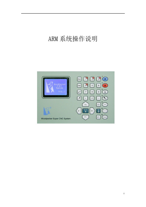
ARM系统说明书V6.5
ARM系统操作说明菜单总图第一章操作说明1. 系统开机后显示第0屏(系统信息屏),见图1:图11)按“”键,机床回零位后,取参数默认值进入第1屏“主界面”。
2)按“”键,机床回零位后,参数取上次保留值进入第1屏“主界面”。
3) 按“”键,机床直接进入第1屏“主界面”,参数取上次保留值。
4) 按“”键,机床直接进入第1屏“主界面”,参数取系统默认值。
2. 进入第1屏(主界面屏),见图2:图2图中(M)表示当前X,Y,Z为机械坐标,(C)表示当前X,Y,Z为工件坐标。
在此屏中可通过按“”键切换;F××表示设定的加工速度是××mm/min;S××表示主轴转速为××转/min;L××表示当前运行的行号;T××表示当前文件加工的时间;(U)表示当前加工的是U盘中的文件。
或(F)表示当前加工的是内存中的文件;05/12/22 16:53表示当天日期和北京时间。
3.按“”键进入参数设定屏(第2屏),见图3:图3按键盘中的复用键' ',' ',' ',' '进入对应屏。
1)按' '键进入机床参数屏(第3屏),见图4:图4在此屏:a)按‘’键进入速度设定屏(第7屏),见图5:图5在第7屏中可以设定加工时的雕刻速度(进给速度),空跑速度(空程速度),手动对刀时的速度(手动速度),此系统的最大速度。
(单位:mm/s)注:在主界面屏,按‘’快捷方式直接进入此屏。
b)按‘’键进入机床设定屏(第8屏),见图6:图6在第8屏中可以设定加工时的起始速度(0.8mm/s),加速度(250mm/ss).螺距数(10mm)和脉冲数(3200转/圈)只能查看不能修改。
c)按‘’键进入原点设定屏(第10屏),见图7:图7在第10屏中可以设定当前加工文件的零点坐标(即原点坐标)。
600TEU操作手册解析

船舶计算机装载系统使用说明书(版本:3.0)目录1、产品简介 (2)2、软件运行环境及硬件说明 (2)3、软件安装 (2)3.1安装 (2)3.2推荐系统 (4)4、软件运行 (4)5、计算条件选择 (5)6、液舱及船舶常数等重量输入 (7)9、集装箱参数输入 (9)7、冷藏集装箱、危险品集装箱配装识别及报警 (11)8、船舶强度核算 (11)9、船舶浮态及稳性核算 (12)10、保存、打开、打印及退出 (14)附录 (15)1 开机 (15)2 关机 (15)3 软件安装与使用密码 (15)4 软件数据保护 (15)船舶计算机装载系统使用说明书1、产品简介集装箱船装载仪(版本3.0)用于集装箱船的配载及船舶性能计算,其主要特点是:1)所设计的界面友好、简洁,操作方便。
2)具有随机计算船舶装载、浮态、强度与稳性的功能,并根据IMO相关规则予以判断。
3)集装箱Bay图操作功能完善。
具有快速装卸的功能,以及集装箱单箱拷贝、粘贴等功能,因而加快了集装箱参数的输入速度。
可用不同的颜色来区分不同卸货港的功能,用户能根据箱位颜色辨别不同卸货港。
4)具有对冷藏集装箱、危险品集装箱配装位置的的识别判断功能;根据IMDG Code要求,对不同种类危险品集装箱的隔离进行识别及报警。
5)输出结果实时、直观,核算结果在图形窗口中以数据和曲线图形相结合的方式显示。
6)完善了打印功能,可以打印完整的各集装箱Bay图以及集装箱Bay位总图,并能打印所有的校核内容。
7)数据库文件管理简便,便于维护、修改和贮存。
2、软件运行环境及硬件说明计算机:PC 586 以上操作系统:WIN98/WIN2000/WINXP/WINNT分辨率:1024X768(推荐)或800X600鼠标:MS-Mouse Compatible打印机:HP Laser Printer Or EPSON Line Printer3、软件安装3.1安装本软件安装步骤如下:(1)打开CD-ROM(2)打开光盘(3)双击“container_setup.exe”,如下图开始安装(4)选择“下一步”(5)选择“下一步”(6)输入安装密码,单击“确定”(7)单击“完成”,完成安装3.2推荐系统WIN98/WIN2000/WINXP/WINNT;1024*7684、软件运行本软件成功安装后,双击桌面图标(快捷方式)即可运行本软件。
yt500定位器说明书

yt500定位器说明书YTC2500智能定位器安装及操作说明书※气路连接●连接定位器的输出与气动执行器的气缸●使用与定位器气源端口处标识的标准接口连接气源●气源连接口前方必须安装过滤器或带有过滤器的空气过滤减压阀,防止水分、油污等异物渗入●确认定位器反馈杆动作方向与执行机构运行方向一致※电气连接根据下列接线端子图以及设计要求进行相应的配线接线端子名称接线方式IN+电流输入信号端子DC4-20mA负载等效电阻Max.410ΩIN-FG接地端子安全保护地OUT+反馈信号端子外接+24V供电反馈电流4-20mAOUT-※调试步骤1.接通气源,检查减压阀后压力是否符合执行器的铭牌参数要求,供气压力范围是0.14-0.7MPa(1.4‐7kgf/cm2),请不要超过这个范围使用;2.接通4---20mA输入信号。
(定位器的工作电源取自输入信号,由DCS二线制供电,不能将DC24V直接加至定位器,否则有可能损坏定位器电路);3.检查位置反馈杆的机械安装,拆下气缸锁定螺丝,并检查气源管路防止漏气;4.手动方式检查执行机构动作,●在运行模式下,按住键6秒,直至屏幕显示[AUTO CAL]●按键或键,切换屏幕显示[MANUAL]●按下键,进入手动方式,屏幕显示[*MA xxx],其中xxx为手动设定指令,可使用键盘操作执行机构动作●按下键或者键可以手动控制气缸慢速动作,按住键同时按下键或者键可以手动控制气缸快速动作,手动操作无误后,按键退出手动操作模式●手动操作时,检查气缸的开关位置能否到位,动作速度是否正常,定位器及管路是否有漏气。
5.进入自动整定●在运行模式下,按住键6秒,直至屏幕显示[AUTO CAL]●按下键,屏幕显示[AUTO1]●按键或键,切换屏幕显示[AUTO2]●按下键,定位器开始自动整定,整定结束后屏幕显示[COMPLETE],并自动保存退出至运行模式下6.如阀门动作方向与输入信号方向相反,则需要切换正反作用●在运行模式下,按住键6秒,直至屏幕显示[AUTO CAL]●按键或键切换,直至屏幕显示[VALVE]●按键进入菜单项,屏幕显示[ACT]●按键,屏幕显示[*ACT]●按键或键切换正反作用,并按键确认保存(屏幕显示为正作用[+ACT RA]或反作用[+ACT DA])7.如定位器屏幕显示与风门开度相反,则需要切换正反开度显示●在运行模式下,按住键6秒,直至屏幕显示[AUTO CAL]●按键或键切换,直至屏幕显示[VIEW]●按键进入菜单项,屏幕显示[YT2500L]或[YT2500R]●按键或键切换,直至屏幕显示[VM]●按键,屏幕显示[*VM]●按键或键切换正反方向开度显示,并按键确认保存(屏幕显示为[+VM NOR]正方向显示或反方向显示[+VM REV])智能定位器程序功能图解1.功能模式:运行模式:即定位器远方操作模式,定位器接收远方操作信号来控制气缸动作,并在屏幕上显示[RUN]。
- 1、下载文档前请自行甄别文档内容的完整性,平台不提供额外的编辑、内容补充、找答案等附加服务。
- 2、"仅部分预览"的文档,不可在线预览部分如存在完整性等问题,可反馈申请退款(可完整预览的文档不适用该条件!)。
- 3、如文档侵犯您的权益,请联系客服反馈,我们会尽快为您处理(人工客服工作时间:9:00-18:30)。
择 , 否 则,按 键 将 自 动 消 失 。 )
登 录 界 面(图6 - 1 )
(图6 - 2 )
系 统 主 界 面(图5 )
子 菜 单(图7 )
快速设置顺序依次为:① 业务设置(新增或修改业务、票面设置)
②
(新增或修改按键) ③ 系统设置( 本机为主机、 号码分段、
设置打印机类型) ④ 退出设置 ⑤正常取票出票。
AUDIO
自动开关机板接口
(图3 )
TOUCH
-4-
参数
物 理 尺 寸: 1 5 3 0 X 4 5 5 X 4 2 0 m m 机 柜 材 质:全 钢 板,金 属 烤 漆 主 控:嵌 入 式 双 处 理 工 控 主 机
S3S2440+SM502 64M SDRAM 64M NAND FLASH 1 0 / 1 0 0 M自 适 应 卡 显 示 器: 1 7寸 液 晶 显 示 器 触 摸 屏: 1 7寸 触 摸 屏 打 印 头 寿 命:大 于1 5 0 k m 切 刀 寿 命:大 于1 0 0万 次 打 印 速 度: 1 5 0 m m / s 打 印 纸 宽: 8 0 m m 电 源: A C 2 2 0 V 5 0 H Z 最 大 功 耗: 7 5 W
此 时 在 屏 幕 的 左 上 方 出 现 四 个 按 键,如 图6 - 2所 示 : 主 机 设 置 、
7 89
L E D显 示 屏 设 置 、L E D显 示 屏 测 试 、 退 出 。 选 择 主 机 设 置 , 进 入 后 0 清零 退格
台 设 置 界 面,如 图7所 示 。 ( 注 意 : 按 键 出 现 后 , 须 在3秒 内 进 行 选 确定 取消
客户听的
无线语音系统(或在显示屏里的语音系统)
工作人员用的
多功能叫号器
系统拓扑图:
请2 0 1 4号 到0 4窗 口 请2 0 1 3号 到0 2窗 口
欢迎光临
请2 0 1 3号
欢迎光临
请2 0 1 4号
系 统 拓 扑 图 ( 图4)
出 厂 前,主 机 显 示 的 背 景 图 、 业 务 按 钮 、 业 务 名 称 、 打 印 号 票 内 容 均 已 设 置 好 。
深 圳 永 泰 新 欣 科 技y o u n g t e k t e c h n o l o g y c o . , l t d
第一章 基本概念
永泰全无线排队系统,不需要布线,插上电源即可使用。
一般营业厅配置一套排队叫号系统包含以下部分:
客户用的
发号主机
客户看的
显示屏(集中呼叫显示屏、窗口屏、多媒体播放器等)
1.2 优先级设置思路 直 接 在 叫 号 器 上 设 置 , 每 个 叫 号 器 可 办 理 的 业 务 种 类 达26个 , 优 先 级 可 达
8层 。 举 一 个 银 行 的 例 子 :
1~5号窗口为储蓄窗口,6号窗口为对公窗口,可以这样设置: 1~4号 窗 口:贵 宾 业 务(优 先 级1 )、 储 蓄 业 务(优 先 级2 )、 对 公 业 务(优 先 级3 ) 5号 窗 口 : 贵 宾 业 务(优 先 级1)、 对 公 业 务(优 先 级2 )、 储 蓄 业 务(优 先 级3 ) 6号 窗 口 : 对 公 业 务(优 先 级1 )、 贵 宾 业 务(优 先 级2 )、 储 蓄 业 务(优 先 级3 ) 这 样 设 置 既 优 先 了 贵 宾 客 户,又 不 至 于 使 普 通 客 户 等 待 太 久,而 且 还 可 以 当 储 蓄
1.1 主机上的业务按钮可增加或减少
例如: 贵 宾 业 务1个 队 列 、 储 蓄 业 务1个 队 列 、 对 公 业 务1个 队 列 、 其 他 业 务1个 队 列,
号码分布分别按如下排列顺序: 贵 宾 业 务 队 列 :1 0 0 1 1 0 0 2 1 0 0 3至1 9 9 9 储 蓄 业 务 队列:2 0 0 1 2 0 0 2 2 0 0 3至2 9 9 9 对 公 业 务 队列:3 0 0 1 3 0 0 2 3 0 0 3至3 9 9 9 其 他 业 务 队 列 :4 0 0 1 4 0 0 2 4 0 0 3至4 9 9 9 四位号码的第一位表示业务种类,后三位表示排队号码。 业 务 种 类 用1 - 9或A - Z来 表 示 的 , 它 代 表 业 务 名 称 , 方 便 叫 号 器 上 的 设 置 。 用户设置前首先从发号主机上按出每个按钮的号票,号票上有业务名称和业务 种 类,然 后 再 按 照 营 业 厅 的 业 务 流 程 需 求 , 以 叫 号 器 为 单 位 单 独 设 置 工 作 人 员 窗 口 号、可办理的业务种类及优先级。叫号器设置方式请参考《多功能叫号器说明书》。
-5-
深 圳 永 泰 新 欣 科 技y o u n g t e k t e c h n o l o g y c o . , l t d
窗口暂无储蓄客户时分流对公客户,当对公窗口暂无对公客户时可分流储蓄客户,使 各窗口的工作负荷相对均衡,效率得以提高。
1.3 可以设置发号主机的背景图 1 . 4 可 以 修 改显示 屏 的信息(欢 迎 词、屏 地 址) 1.5 可以修改语音的音量 1.6 可以重新编辑号票的内容 1.7 按键可分时间段显示或隐藏 1 . 8 V IP刷卡 可以分 卡 段或分 类 设置
-3-
深 圳 永 泰 新 欣 科 技y o u n g t e k t e c h n o l o g y c o . , l t d
外 观 图 解:
触摸显示区 二代身份证识别区
出票口
发 号 主 机 正 面(图1 )
二代身份证 感应读卡器
V G A接 口
打印 控制板
打印纸
V G A接 口
电源 启动键 网口
3.1 进入主机设置界面 .................................6 3.2 业务设置(新 增或删 除 业务、 设 计票面 及 下载票 面) ...7 3.3 按键(钮)图片、背景图片、号票logo的预处理 ........8 3.4 背景图片和按键设置 ...............................8 3.5 系统设置 ..................................10 3.6 语音设置...................................14 3.7 屏幕校准...................................14 3.8 退出设置...................................14 第四章 LED显示屏设置 ...............................15 4.1 操作流程图 .................................15 4.2 使用说明 ...................................15 4.3 设置窗口显示屏 ..............................16 . 4.4 设置集中显示屏 ..............................20 第五章 常见故障排除 .................................22
深圳市永泰新欣科技有限公司
-1-
深圳永泰新欣科技 youngtek technology co.,ltd
安全信息:
发号主机放置点请勿靠近高温源(如火、加热器等)以免液晶屏受损、机壳变形。 请勿放置在潮湿、温度变化大、冷暖风直吹及灰尘多的地方,以免产生漏电、卷 纸转不动、误动作等故障。设备摆放好后,应避免冲击和敲打。 请勿用尖锐、锋利的器具点触或重压触摸屏。设备表面有灰尘时,用细布擦干即 可,不可使用清洁剂或其他化学溶剂,以免损坏机壳表面或流入设备内部损坏元 件。 开、关电源后一分钟内不要马上再关掉或打开电源,特别是在打印机工作时,严 禁中途关机,以防止出现卡纸、数字错乱等现象。 电源插头要插实,不要用力拉、拔、扭曲,造成接触不良导致主机无法正常工作。 为安全起见,长时间不用时请拔下电源插头。 若使用过程中发现机器有冒烟、异味等现象时,应立即关闭电源,检查排除故障。 显示屏应悬挂在等候区附近显眼处,面向顾客,避免阳光或强光直射显示屏。 多 功 能 叫 号 器 放 在 柜 台 人 员 的 台 面 上 , 方 便 操 作 。 几 个 叫 号 器 同 时 按 键 时,主 机 依 次受理。因此在按键后听到叫号器发出“嘀”的声响,说明已经受理,不要再次按 键,以免发生连续呼叫。
尊 敬 的 用 户:
您好! 非常感谢您购买永泰全无线排队机,使我们有机会为您提供服务。我们会 尽最大的努力,使排队机的功能更贴近您的业务流程和实际需求,让您充分享 受永泰排队机卓越的性能和优良的品质所带给您的便捷服务。 我们希望这本“使用说明书”能成为您在调整和设置业务种类、业务优先 级以及更多功能过程中的一个好帮手。 您的满意是我们服务的目标。我们会不断努力,秉承“专业精神,精益求 精”的理念,力求做到最好。
深圳永泰新欣科技 youngtek technology co.,ltd
触摸屏式无线排队机 使用说明书
请2 0 1 6号 到0 8窗 口 请2 0 1 3号 到0 2窗 口
欢迎光临
请2 0 1 3号
欢迎光临
请2 0 1 6号
深圳市永泰新欣科技有限公司
深圳永泰新欣科技 youngtek technology co.,ltd
打印纸卡纸的清除步骤:
1 .打 开 支 架 开 关 阀,逆 时 针 旋转支架,可看到打印机头。 2 .打 印 机 头 左 下 方 有 一 个 绿色按钮,向下掰。 3 .打 印 机 滚 轴 露 出 。 4 .轻 轻 将 纸 屑 拿 掉 。 5 .复 位 。
V G A接 口
C O M 4刷 卡 器
刷卡器主板安装放大图
主 机 内 部(图2 )
无线收发模块
