Testing Acoustic Frequency Response
Acoustic-Emission-TestingPPT课件

Acoustic Emission Testing
-
1
Introduction to Acoustic Emission Testing
• 材料中因裂缝扩展、塑性变形或相变等引 起应变能快速释放而产生应力波的现象称 为声发射。
-
2
声发射技术
•
通过接收和分析材料的声发射信号来
评定材料的性能或结构完整性。
• The first difference pertains to the origin of the signal. Instead of supplying energy to the object under examination, AET simply listens for the energy released by the object.
-
10
Attenuation (衰减)
• geometric spreading. • material damping • wave scattering
Geometric discontinuities (e.g. twin boundaries, nonmetallic inclusions, or grain boundaries) and structural boundaries both reflect some of the wave energy that was initially transmitted
-
6
Activity of AE Sources in Structural Loading
Basic AE history plot showing Kaiser effect (BCB), Felicity effect (DEF), and emission during hold (GH ) 2
无损检测种类

在不损伤被测材料的情况下,检查材料的内在或表面缺陷,或测定材料的某些物理量、性能、组织状态等的检测技术。
广泛用于金属材料、非金属材料、复合材料及其制品以及一些电子元器件的检测。
常用的无损检测技术有:①射线探伤(radiographic testing)。
利用X射线或γ射线在穿透被检物各部分时强度衰减的不同,检测被检物的缺陷。
若将受到不同程度吸收的射线投射到X射线胶片上,经显影后可得到显示物体厚度变化和内部缺陷情况的照片。
如用荧光屏代替胶片,可直接观察被检物体的内部情况。
②超声检测(ultrasonic testing)。
利用物体自身或缺陷的声学特性对超声波传播的影响,来检测物体的缺陷或某些物理特性。
在超声检测中常用的超声频率为0.5~5兆赫(MHz)。
最常用的超声检测是脉冲探伤。
③声发射检测(acoustic emission testing)。
通过接收和分析材料的声发射信号来评定材料的性能或结构完整性。
材料中因裂缝扩展、塑性变形或相变等引起应变能快速释放而产生应力波的现象称为声发射。
材料在外部因素作用下产生的声发射,被声传感器接收转换成电信号,经放大后送至信号处理器,从而测量出声发射信号的各种特征参数。
④渗透探伤(penetrant testing)。
利用某些液体对狭窄缝隙的渗透性来探测表面缺陷。
常用的渗透液为含有有色染料或荧光的液体。
⑤磁粉探伤(magnetic testing)。
通过磁粉在物体缺陷附近漏磁场中的堆积来检测物体表面或近表面处的缺陷,被检测物体必须具有铁磁性。
此外,中子射线照相法、激光全息照相法、超声全息照相法、红外检测、微波检测等无损检测新技术也得到了发展和应用。
在无损检测的五大常规检测中(UT 、RT、ET、MT、PT),没有声发射检测.应该是涡流检测(eddy current testing):涡流检测是建立在电磁感应原理基础之上的一种无损检测方法.它适用于导电材料.如果我们把一块导体置于交变磁场之中,在导体中就有感应电流存在,即产生涡流.由于导体自身各种因素(如电导率,磁导率,形状,尺寸和缺陷等)的变化,会导致感应电流的变化,利用这种现象而判知导体性质,状态的检测方法叫做涡流检测方法.。
电气英语专业英语词汇2

ance indicator------交流平衡指示器dge------交流电桥rent calibrator------交流电流校准器rent distortion------交流电流失真uced polarization instrument------交流激电仪entiometer------交流电位差计istance box------交流电阻箱ndard resistor------交流标准电阻器tage distortion------交流电压校准器tage distortion------交流电压失真mparator------阿贝比长仪on------象差f anti prereduced component------抗先还原物质能力 thickness transducer [sensor]------烧蚀厚度传感器n testing machine------磨损试验机e calibration------绝对法校准e coil------独立线圈e error------绝对误差e)error of measurement------测量的(绝对)误差e gravimeter------绝对重力仪e gravity survey------绝对重力测量e humidity------绝对湿度e method------绝对法e moisture of the soil------土壤(绝对)湿度e pressure------绝对压力e(pressure transducer------绝对压力表e pressure transducer[sensor]------绝对压力传感器e read-out------单独读出e resolution------绝对分辨率e salinity------绝对盐度e stability------绝对稳定性e stability of a linear system------线性系统的绝对稳定性e static pressure of the fluid------流体绝对静压e temperature scale------绝对温标nce------吸光度d current image------吸收电流象ance------吸收比iometer------吸收光度计ion cell------吸收池该帖子于2007-6-5 23:03:33被冰豆浆编辑过。
声发射检测
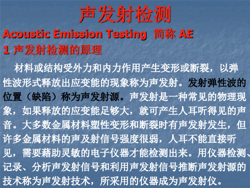
(5)复合材料:研究和测量复合材料内基体和纤维的断 复合材料: 脱开、分层和整体失效等; 裂、脱开、分层和整体失效等; 磁性材料:通过测量磁声发射的信号, (6)磁性材料:通过测量磁声发射的信号,研究磁性材 料的某些特性; 料的某些特性; 陶瓷材料:研究陶瓷材料的受力和破坏特性, (7)陶瓷材料:研究陶瓷材料的受力和破坏特性,对陶 瓷材料进行无损评估; 瓷材料进行无损评估; 核工业领域:对核容器和管道的泄漏进行监测, (8)核工业领域:对核容器和管道的泄漏进行监测,对 核压力容器进行无损检测和安全评定; 核压力容器进行无损检测和安全评定; 焊接过程控制: (9)焊接过程控制:通过实时监测焊接过程中金属冷却 产生的声发射信号来控制焊接质量; 产生的声发射信号来控制焊接质量; 10) 机械加工: ( 10 ) 机械加工 : 通过探测机械加工过程中产生的声发 射 信号,监测刀具的磨损情况; 信号,监测刀具的磨损情况; 11) 机械诊断: ( 11 ) 机械诊断 : 通过监测机器在运转过程中产生的声 发 诊断机器轴承的磨损情况。 射信号 ,诊断机器轴承的磨损情况。
12) 医学领域 : 研究骨头的摩擦 |受力和破坏特性 , 无 12)医学领域:研究骨头的摩擦|受力和破坏特性, 损 检测和评价骨关节的状况。 检测和评价骨关节的状况。
4
压力容器的声发射检测(球罐、尿素合成塔、 压力容器的声发射检测(球罐、尿素合成塔、
长管拖车) 长管拖车)
a 准备工作 b 布置换能器和校准声发射仪器 c 升压并进行声发射检测 d 检测结果的分析与评价
5 储油罐的泄漏检测(地下加油站) 储油罐的泄漏检测(地下加油站)
5 声发射检测特点
a 能够检测出活动的缺陷,即材料的断裂和裂纹的扩展, 能够检测出活动的缺陷,即材料的断裂和裂纹的扩展, 从而为使用安全性评价提供依据; 从而为使用安全性评价提供依据; b 可远距离操作,长期监控设备允许状态和缺陷扩展情 可远距离操作, 况; c 无法探测静态缺陷; 无法探测静态缺陷; d 设备价格昂贵; 设备价格昂贵; e 检测过程中干扰因素较多; 检测过程中干扰因素较多; f 声发射检测完成后,一般需要常规无损检测方法(UT) 声发射检测完成后,一般需要常规无损检测方法(UT) 复验。 复验。
AudioPresion测试项英文翻译

序號
模塊
測試項(英文)
1
Acoustic response
2
Impedance
3 acoustic(聲學) Loudspeaker production test
4
Modulated noise
5
Teds data
5
Crosstalk,one channel undriven
6
19
Continuous sweep
20
IMD(DFD/MOD/SMPTE/CCIF)
21
IMD(DFD/MOD/SMPTE/CCIF)Frequency Sweep
22
IMD(DFD/MOD/SMPTE/CCIF)Level Sweep
23 24
Distortion(
失真)
Measurement Recorder Modulated Noise
67
IMD(DFD/MOD/SMPTE/CCIF)Level Sweep
68
Measurement Recorder
69
Metadata Recorder
70
Noise Recorder(RMS)
71
Regulated Frequency Sweep
72
Stepped Frequency Sweep
73
Stepped Level Sweep
74
Rub & Buzz Rub & Buzz
照
中文
声波响应 阻抗 扬声器生产测试 调制噪声 撒开数据 串擾,一個通道 频率响应 通道间相位, 相位 电压和增压 信噪比 總諧波失真 連續掃描 相聲(串話干擾)掃描 串扰扫描,一个通道驱动 串扰扫描,一个通道不驱动 相聲(串話干擾),客戶自定義 串扰,一个通道驱动 串扰,一个通道不驱动 声波响应 连续扫描 互調失真 互調失真 互調失真 测量记录器 调制噪声 多频声分析仪 监管频率扫描 信噪比 步进频率扫描 步进电平扫描 带通等级 共模抑制比 相聲(串話干擾),客戶自定義 串扰,一个通道驱动 串扰,一个通道不驱动 直流电平 直流电平 動態範圍 频率 互調失真 输入采样率
Acoustic Emission Testing
返回
Acoustic Emission is unlike most other nondestructive testing (NDT) techniques in two regards.
• The first difference pertains to the origin of the signal. Instead of supplying energy to the object under examination, AET simply listens for the energy released by the object. • The second difference is that AET deals with dynamic processes, or changes, in a material. • (AE systems can only qualitatively gauge how much damage is contained in a structure.)
Equipment
AE Signal Featon Techniques
Linear Location Technique
Zonal Location Technique
Point Location
Applications
• Noise To compensate for the effects of background noise, various procedures can be implemented. Some possible approaches involve fabricating special sensors with electronic gates for noise blocking, taking precautions to place sensors as far away as possible from noise sources, and electronic filtering (either using signal arrival times or differences in the spectral content of true AE signals and background noise). • Pseudo Sources
无线蓝牙耳机电子产品可靠性试验标准中英文版模板
⽆线蓝⽛⽿机电⼦产品可靠性试验标准中英⽂版模板RODUCT reliability Test standard产品可靠性试验标准Product Type: True Wireless EarphonesModel:Document No.REVISIONSApprovalsContents1Purpose (1)2Policy (1)3Safety (1)4RESPONSIBILITY (1)5SAMPLING PLAN (1)5.1Total Samples Required (1)5.2Sample grouping (1)5.3Unit Marking: (2)5.3.1Sampling Plan Visual Tests (2)5.3.2Sampling Plan Function Tests (2)5.3.3Sampling Plan Product Reliability Tests (3)5.3.4Sampling Plan Mechanical Validation and Life Tests (3)5.3.5Sampling Plan Packaging Tests (4)5.3.6Sampling Plan Compliance Validation Tests (4)6PROCEDURE (5)6.1Test Definitions and Descriptions for Visual Tests (5)6.1.1External Visual Examination (5)6.1.2Internal Visual Examination (5)6.2Test Definitions and Descriptions for Function Tests (6)6.2.1Manual Listening and Calling Test (6)6.2.2Frequency Response (6)6.2.3Mic Sensitivity Test (6)6.2.4THD Test (7)6.2.5Audio Balance Test (7)6.2.5Audio Balance Test (ANR Off) (7)6.2.6Audio Balance Test (ANR On) (7)6.2.7NC Stability test (7)6.2.8Hiss Noise Test (7)6.2.9ANR Test (7)6.3Test Definitions and Descriptions for Product Reliability Tests (7)6.3.1Continuous Max. Output Power Test (7)6.3.2Non Operational Thermal Shock Test (7)6.3.3Operational Temperature / Humidity Cycle Test (8)6.3.4Non Operational Temperature / Humidity Cycle Test (9)6.3.5Driver Deformation Test (10)6.4Test Definitions and Descriptions for Mechanical Validation and Life Tests (10) 6.4.1Cable Flexing Test (10)6.4.2Cable Tensile Strength Test (11)6.4.3Insertion & Extracting Test (11)6.4.4Bluetooth test (11)6.4.5Switch Life Test (12)6.4.6Charging Pin Life Test (12)6.4.7USB Socket Withstand Force Test (12)6.4.8Drop Test (12)6.4.9Vibration Test (13)6.4.10Charge Time Test (13)6.4.11Music Play Time Test (13)6.4.12ESD Test (13)6.4.13Decorative Surface Tests (14)6.4.14Standby Time Test (18)6.4.15RCA Test For Coating Parts (18)6.4.16Free fall repeat Test (18)6.5Test Definitions and Descriptions for Packaging Validation (18)6.5.1Retail Packaging Drop Test (18)6.5.2Shipping Carton Vibration Test (19)6.5.3Shipping Carton Piling Up Test (19)6.5.4Shipping Carton Packaging Storage Test (19)6.5.5Shipping Carton Drop Test (20)6.6Test Definitions and Descriptions for Compliance Validation (21)6.6.1EMC Test (21)6.6.2RoHS Compliance Test (21)6.6.3REACH Compliance Test (21)6.7IPX5 Protection against water Test (21)7ANNEXES (23)1PurposeThis document explains the sequence of testing to be used to verify the Bluetooth headset .本⽂档诠释了⽤于验证蓝⽛⽿机的测试顺序。
国外主要无损检测标准题录(超声检测)

国外主要无损检测标准题录(超声检测)发布时间:10-10-15 来源:点击量:1740 字段选择:大中小国际标准:ISO 2400-72E 用于校准超声检测设备的钢焊件参考试块(用于t≤50mm钢管焊缝)(INDT,82-4)Welds in steel -- Reference block forthe calibration ofequipment for ultrasonic examinationISO 4064-3-99 封闭管道中液体流量的测量使用速调整超声流量计法ISO 4386/1:1992 金属多层滑动轴承第1部分:粘接强度的超声无损检验Plainbearings -- Metallic multilayer plain bearings -- Part1:Non-destructive ultrasonic testing of bondISO 4386/2 金属多层滑动轴承第2部分:支承面金属层厚度≥2mm的粘接破坏性试验ISO 5180-80 超声检验用钢制校准试块ISO 5577:2000 无损检测--超声检测--术语Non-destructive testing -- Ultrasonic inspection--VocabularyISO 9303:1989 无缝和焊接(埋弧焊除外)承压钢管--探测纵向缺陷的全圆周超声检验Seamless and welded (except submerged arc-welded) steeltubesfor p ressure purposes -- Full peripheral ultrasonictesting for thedetectio n of longitudinal imperfectionsISO 9305:1989 无缝承压钢管--探测横向缺陷的全圆周超声检验Seamless steel tubes for pressure purposes -- Full peripheralultr asonic testing for the detection of transverseimperfectionsISO 9764:1989 电阻焊和感应焊承压钢管--探测焊缝纵向缺陷的超声检验Electric resistance and induction welded steel tubes forpressure purposes -- Ultrasonic testing of the weld seam for thedetection of l ongitudinal imperfectionsISO 9765:1990 埋弧焊承压钢管--探测焊缝纵向及/或横向缺陷的超声检验Submerged arc-welded steel tubes for pressure purposes --Ultrason ic testing of the weld seam for the detection oflongitudinal and/or t ransverse imperfectionsISO 10124:1994 受压无缝和焊制(埋弧焊除外)钢管分层缺陷的超声检测Seamless andwelded (except submerged arc-welded) steel tubesfor p ressurepurposes -- Ultrasonic testing for the detection oflaminarimpe rfectionsISO 10332:1994 受压无缝和焊制(埋弧焊除外)钢管验证水压密封性的超声检测Seamless andwelded (except submerged arc-welded) steel tubesfor p ressurepurposes -- Ultrasonic testing for the verification ofhydrauli cleak-tightnessISO 10375:2002 无损检测--超声检验--探头及其声场的表征Non-destructive testing -- Ultrasonic inspection - -Characterizat ion of search unit and sound fieldISO 10543:1993 无缝和热拉缩径焊接承压钢管--全圆周超声厚度检查Seamless and hot-stretch-reduced welded steel tubes forpressure p urposes -- Full peripheral ultrasonic thicknesstestingISO 11496:1993 无缝和焊接承压钢管--探测管端头分层缺陷的超声检验Seamless and welded steel tubes for pressure purposes --Ultrasoni c testing of tube ends for the detection of laminarimperfectionsISO12094:1994 受压焊制钢管焊制钢管制造用钢带/钢板分层缺陷的超声检测Welded steel tubes for pressure purposes -- Ultrasonictestingfor the detection of laminar imperfections in strips/platesused inthe man ufacture of welded tubesISO12710:2002 无损检测超声检测超声检测仪的电子特性评估Non-destructive testing -- Ultrasonic inspection --Evaluatingelec tronic characteristics of ultrasonic testinstrumentsISO 12713:1998 无损检测--声发射检测--换能器的初次校正Non-destructive testing -- Acoustic emission inspection --Primary calibration of transducersISO 12714:1999 无损检测--声发射检查--声发射传感器的二次校准Non-destructive testing -- Acoustic emission inspection --Seconda ry calibration of acoustic emission sensorsISO 12715:1999 无损检测--超声检测--表征接触式探头声束轮廓的参考试块和测试方法Ultrasonic non-destructive testing -- Referenceblocks and testpro cedures for the characterization of contactsearch unit beamprofilesISO 12716:2001 无损检测--声发射检验--术语Non-destructive testing -- Acousticemission inspection --Vocabula ryISO13663:1995 受压焊制钢管焊缝附近分层缺陷的超声检测Welded steeltubes for pressure purposes -- Ultrasonic testingof t he areaadjacent to the weld seam for the detection oflaminarimperfect ionsISO 17640:2005 焊缝无损检测--焊缝超声检测Non-destructive testing of welds --Ultrasonic testing ofwelded jo intsISO 18175:2004 无损检测--超声脉冲回波检测系统工作特性评价(不用电子测量仪器)Non-destructive testing -- Evaluatingperformancecharacteristics o f ultrasonic pulse-echo testingsystemswithout the use of electronic m easurement instrumentsISO DIS 12709:1998 用超声脉冲回波水浸法检测和评价缺陷ISO 22825:2006 焊缝无损检测--超声检测--奥氏体不锈钢与镍基合金焊缝的检测Non-destructive testing of welds -- Ultrasonic testing--Testing o f welds in austenitic steels andnickel-basedalloysISO 23279 焊缝无损检测--超声检测--焊缝的指示特征ISO/CD 25902-2 钛管无损检测--第2部分:超声检验ISO/DP4992-83 铸钢件的超声波检测(INDT,85-2)ISO(1984-02-07) 铸钢件超声波探伤草案(WSTS,88-4,5)IIWVC-421-83,VF-141-83 焊缝常规超声检验验收标准(7-100mm铁素体钢对接焊缝)(INDT,85-3)IIW DOC V-527-76 焊缝超声检验手册IIW DOC V-664-79 用AVG图直接评估超声反射信号的验收标准(NDT,80-2)欧洲标准化委员会标准:EN 583/1:1998 无损检测超声检验第1部分:一般原理Non-destructivetesting-Ultrasonic examination-Part 1:Generalprinc iplesEN 583/2:2001 无损检测超声检验第2部分:灵敏度和范围的调整(NDI,2 004.4)(NDT2005.8)Non-destructive testing-Ultrasonicexamination-Part2:Sensitivity a nd range settingEN 583/3:1999 无损检测超声检验第3部分:透射技术Non-destructivetesting-Ultrasonic examination-Part3:Transmission techniqueEN 583/4:2002/A1:2003 无损检测超声检验第4部分:垂直于表面的不连续性的检验Non-destructive testing-Ultrasonicexamination-Part4:Examination f or discontinuities perpendicular tothesurfaceEN 583/5:2000/A1:2003 无损检测超声检验第5部分:缺陷的表征和尺寸确定Non-destructive testing-Ultrasonicexamination-Part5:Characterizat ion and sizing ofdiscontinuitiesENV 583/6:2000 无损检测超声检验第6部分:用于缺陷探测和定量的衍射时差法Non-destructive testing-Ultrasonicexamination-Part6:Time-of-fligh t diffraction technique as a methodfor detectionand sizing of discont inuitiesEN 1330/4:2000 无损检测词汇超声检测所用术语Non-destructivetesting-Terminology-Part 4:Terms used inultrasonic testingEN 1330/9:2000 无损检测词汇声发射检测所用术语EN 1712:1998(2003) 焊接的无损检验焊接接头的超声检验验收等级Non-destructive examination of welds-Ultrasonic examination ofwel dedjoints-Acceptance levelsEN 1713:1998(2003) 焊接的无损检验超声检验焊缝中的显示特征Non-destructive examination ofwelds-Ultrasonicexamination-Charact erization of indications inweldsEN 1714:1997(2003) 焊接的无损检验焊接接头的超声检验Non-destructive examination ofwelds-Ultrasonicexamination of weld ed jointsEN 10160:1999 厚度等于或大于6mm钢制平产品厚度的超声检测EN 10228/3:1998 钢锻件无损检测铁素体或马氏体钢锻件的超声检测EN 10228/4:1999 钢锻件无损检测奥氏体和奥氏体铁素体不锈钢锻件的超声检测EN 10246/6:1999 钢管的无损检测无缝钢管横向缺陷的全圆周超声检测EN 10246/7:1996 钢管的无损检测无缝和焊接(埋弧焊除外)钢管纵向缺陷的自动全圆周超声检测EN 10246/8:1999 钢管的无损检测电焊钢管焊缝纵向缺陷的自动超声检测EN 10246/9:2000 钢管的无损检测埋弧焊钢管焊缝纵向及/或横向缺陷的自动超声检测EN 10246/13:2000 钢管的无损检测无缝和焊接(埋弧焊除外)钢管全圆周自动超声测厚EN 10246/14:1999 钢管的无损检测无缝和焊接(埋弧焊除外)钢管层状缺陷的自动超声检测EN 10246/15:2000 钢管的无损检测制造焊接钢管用的带材/中厚板层状缺陷的自动超声检测EN 10246/16:2000 钢管的无损检测焊接钢管焊缝附近区域层状缺陷的自动超声检测EN 10246/17:2000 钢管的无损检测无缝和焊接钢管管端面层状缺陷的超声检测EN 12223:2000 无损检测超声检验1号校准块规范Non-destructivetesting-Ultrasonic examination-Specificationfor ca libration blockNo.1EN 12668/1:2000/A1:2004 超声检验设备的特性和校验第1部分:仪器Non-destructivetesting-Characterization and verification ofultras onic examinationequipment-Part 1:InstrumentsEN 12668/2:2001/A1:2004 超声检验设备的特性和校验第2部分:探头Non-destructivetesting-Characterization and verification ofultras onic examinationequipment-Part 2:ProbesEN 12668/3:2000/A1:2004 超声检验设备的特性和校验第3部分:组合设备Non-destructivetesting-Characterization and verification ofultras onic examinationequipment-Part 3:Combined equipmentEN 13477/1:2001 无损检测声发射设备表征第1部分:设备描述Non-destructivetesting-Acoustic emission-Equipmentcharacterisatio n-Part1:Equipment descriptionEN 13477/2:2001 无损检测声发射设备表征第2部分:工作特性的校验Non-destructive testing-Acousticemission-Equipmentcharacterisatio n-Part 2:Verification ofoperatingcharacteristicEN 13554:2002/A1:2003 无损检测声发射一般原理Non-destructive tes ting-Acousticemission-GeneralprinciplesEN 138052-1:2001 超声测厚EN 138052-2:2001 超声自动检测EN 14127:2004 无损检测超声测厚Non-destructivetesting-Ultrasonic thickness measurementCEN/TS 14751:2004 焊缝超声TOFD法检测EN 27963:1992 用于焊缝超声检验的2号校准试块规范Weldsin steel-Calibration block No.2 for ultrasonicexamination of welds(ISO 7963:1985)EN 61161: 在液体中频率范围0.5MHz~25MHz超声功率测量规范EN WI-188:1999 奥氏体钢焊缝超声检测方法EN WI-189:1999 铝和铝合金焊缝超声检测方法EN WI-190:1999 金属焊缝超声自动检测方法EN WI-191:2000 钢电子束和激光焊缝超声检测方法前苏联标准:гост 21397-75 铝合金制品超声检测用标准试块的基本参数与技术要求гост 23702-79 超声换能器基本参数及其测量方法(INDT,83-3)гост 23667-79 超声探伤仪基本参数测量方法гост 23049-78 超声检测的一般技术要求гост 22727-77 薄钢板致密性的超声检测гост 22368-77 对接焊缝超声检测的缺陷分类гост 21120-75 圆,方,矩形截面棒材与坯料的超声回波法检测гост 20415-82 声学检测一般规则гост 18576-80 铁路钢轨的超声检测гост 17410-78 圆柱形无缝金属管的超声检测гост 14782-76 焊缝的超声检测гост 12503-75 钢的超声检测一般要求гост 51017-71 涡轮机K-200-130-1转子锻件制造标准(含超声检测标准)ПИ1.2. 032-77 航空发动机涡轮盘和压气机盘的超声检验OCT1 90250-77 无损检验用于航空技术装备的半成品和零件的超声检验对检验方法内容和编制的一般要求ISO 5948-81E 铁路机车车辆部件的超声波验收试验(车辆,车轮及轮箍)(ND T,87-4)ISO5948:1994(E) 铁道车辆材料-超声波验收检验(NDT2002-3)Railwayrolling stock material -- Ultrasonic acceptancetestingISO 6721/8:1997 塑料-动态力学性能的测定第8部分:纵波和横波传播法ISO 6721/9:1997 塑料-动态力学性能的测定第9部分:拉伸振动-声脉冲传播法ISO 7963:2006 无损检测--超声检测--钢焊缝--2号校正试块的规范Welds insteel -- Calibration block No. 2 for ultrasonicexaminatio n ofwelds。
无损检测标准术语英语
无损检测标准术语英语无损检测标准术语A.C magnetic saturation^交流磁饱和 Absorbed dose^吸收剂量Absorbed dose rate^吸收剂量率 Acceptanc limits^验收范围Acceptance level^验收水平Acceptance standard^验收标准 Accumulation test^累积检测 Acoustic emission count^声发射计数 emission count^发射计数Acoustic emission transducer^声发射换能器(声发射传感器)Acoustic emission(AE)^声发射 Acoustic holography^声全息术 Acoustic impedance^声阻抗Acoustic impedance matching^声阻抗匹配 Acoustic impedance method^声阻法 Acoustic wave^声波Acoustical lens^声透镜Acoustic^—ultrasonic^声-超声 Activation^活化Activity^活度Adequate shielding^安全屏蔽 Ampere turns^安匝数Amplitude^幅度Angle beam method^斜射法 Angle of incidence^入射角Angle of reflection^反射角Angle of spread^指向角Angle of squint^偏向角Angle probe^斜探头Angstrom unit^埃(A)Area amplitude response curve^面积幅度曲线Area of interest^评定区Artificial discontinuity^人工不连续性 Artifact^假缺陷Artificial defect^人工缺陷Artificial discontinuity^标准人工缺陷 A-scan A^型扫描A-scope; A-scan A^型显示Attenuation coefficient^衰减系数 Attenuator^衰减器Audible leak indicator^音响泄漏指示器 Automatic testing^自动检测Autoradiography^自射线照片 Evaluation^评定Barium concrete^钡混凝土Barn^靶Base fog^片基灰雾Bath^槽液Bayard- Alpert ionization gage B- A^型电离计Beam^声束Beam ratio^光束比Beam angle^束张角Beam axis^声束轴线Beam index^声束入射点Beam path location^声程定位 Beam path; path length^声程 Beam spread^声束扩散Betatron^电子感应加速器Bimetallic strip gage^双金属片计 Bipolar field^双极磁场Black light filter^黑光滤波器 Black light; ultraviolet radiation^黑光 Blackbody^黑体Blackbody equivalent temperature^黑体等效温度Bleakney mass spectrometer^波利克尼质谱仪Bleedout^渗出Bottom echo^底面回波Bottom surface^底面Boundary echo(first)^边界一次回波 Bremsstrahlung^轫致辐射Broad-beam condition^宽射束 Brush application^刷涂B-scan presenfation B^型扫描显示 B-scope; B-scan B^型显示 C- scan C^型扫描Calibration,instrument^设备校准 Capillary action^毛细管作用 Carrier fluid^载液Carry over of penetrate^渗透剂移转 Cassette^暗合Cathode^阴极Central conductor^中心导体 Central conductor method^中心导体法Characteristic curve^特性曲线 Characteristic curve of film^胶片特性曲线Characteristic radiation^特征辐射Chemical fog^化学灰雾Cine-radiography^射线(活动)电影摄影术 Contact pads^接触垫Circumferential coils^圆环线圈 Circumferential field^周向磁场Circumferential magnetization method^周向磁化法Clean^清理Clean- up^清除Clearing time^定透时间Coercive force^矫顽力Coherence^相干性Coherence length^相干长度(谐波列长度)Coi1 test^测试线圈Coil size^线圈大小Coil spacing^线圈间距Coil technique^线圈技术Coil method^线圈法Coil reference^线圈参考Coincidence discrimination^符合鉴别 Cold-cathode ionization gage^冷阴极电离计Collimator^准直器Collimation^准直Collimator^准直器Combined colour comtrast and fluorescent penetrant^着色荧光渗透剂Compressed air drying^压缩空气干燥 Compressional wave^压缩波 Compton scatter^康普顿散射 Continuous emission^连续发射 Continuous linear array^连续线阵 Continuous method^连续法 Continuous spectrum^连续谱 Continuous wave^连续波Contract stretch^对比度宽限 Contrast^对比度Contrast agent^对比剂Contrast aid^反差剂Contrast sensitivity^对比灵敏度 Control echo^监视回波Control echo^参考回波Couplant^耦合剂Coupling^耦合Coupling losses^耦合损失Cracking^裂解Creeping wave^爬波Critical angle^临界角Cross section^横截面Cross talk^串音Cross-drilled hole^横孔 Crystal^晶片C-scope; C-scan C^型显示 Curie point^居里点Curie temperature^居里温度 Curie(Ci)^居里Current flow method^通电法 Current induction method^电流感应法Current magnetization method^电流磁化法Cut,off level^截止电平 Dead zone^盲区Decay curve^衰变曲线Decibel(dB)^分贝Defect^缺陷Defect resolution^缺陷分辨力 Defect detection sensitivity^缺陷检出灵敏度Defect resolution^缺陷分辨力 Definition^清晰度image definition^图像清晰度 Demagnetization^退磁Demagnetization factor^退磁因子 Demagnetizer^退磁装置 Densitometer^黑度计Density^黑度(底片)Density comparison strip^黑度比较片Detecting medium^检验介质 Detergent remover^洗净液 Developer^显像剂Developer station^显像工位 Developer^,agueons^水性显象剂Developer^,dry^干显象剂Developer^,liquid film^液膜显象剂nonaqueous Developer^非水(可悬浮)显象剂sus-pendible^非水(可悬浮)显象剂 Developing time^显像时间Development^显影Diffraction mottle^衍射斑 Diffuse indications^松散指示Diffusion^扩散Digital image acquisition system^数字图像识别系统Dilatational wave^膨胀波Dip and drain station^浸渍和流滴工位 Direct contact magnetization^直接接触磁化 Direct exposure imaging^直接曝光成像 Direct contact method^直接接触法 Directivity^指向性Discontinuity^不连续性Distance- gain- size^距离-增益-尺寸 Distance marker^距离刻度Dose equivalent^剂量当量Dose rate meter^剂量率计Dosemeter^剂量计Double crystal probe^双晶片探头 Double probe technique^双探头法Double transceiver technique^双发双收法 Double traverse technique^二次波法 Dragout^带出Drain time^滴落时间Drain time^流滴时间Drift^漂移Dry method^干法Dry powder^干粉Dry technique^干粉技术Dry developer^干显像剂Dry developing cabinet^干显像柜 Dry method^干粉法Drying oven^干燥箱Drying station^干燥工位Drying time^干燥时间D-scope; D-scan D^型显示Dual search unit^双探头Dual-focus tube^双焦点管Duplex-wire image quality indicator^双线像质指示器Duration^持续时间Dwell time^停留时间Dye penetrate^着色渗透剂Dynamic leak test^动态泄漏检测 Dynamic leakage measurement^动态泄漏测量Dynamic range^动态范围Dynamic radiography^动态射线透照术 Echo^回波Echo frequency^回波频率Echo height^回波高度Echo indication^回波指示Echo transmittance of sound pressure^往复透过率 Echo width^回波宽度Eddy current^涡流Eddy current flaw detector^涡流探伤仪 Eddy current testiog^涡流检测Edge^端面Edge effect^边缘效应Edge echo^棱边回波Edge effect^边缘效应Effective depth penetration^有效穿透深度 EDP^有效穿透深度Effective focus size^有效焦点尺寸 Effective magnetic permeability^有效磁导率 Effective permeability^有效磁导率 Effective reflection surface of flaw^缺陷有效反射面 Effective resistance^有效电阻Elastic medium^弹性介质Electric displacement^电位移Electrical center^电中心Electrode^电极Electromagnet^电磁铁Electro-magnetic acoustic transducer^电磁声换能器Electromagnetic induction^电磁感应 Electromagnetic radiation^电磁辐射 Electromagnetic testing^电磁检测 Electro-mechanical coupling factor^机电耦合系数 Electron radiography^电子辐射照相术 Electron volt^电子伏恃Electronic noise^电子噪声Electrostatic spraying^静电喷涂Emulsification^乳化Emulsification time^乳化时间Emulsifier^乳化剂Encircling coils^环绕式线圈End effect^端部效应Energizing cycle^激励周期Equalizing filter^均衡滤波器Equivalent^当量Equivalent I(Q. I. Sensitivity^象质指示器当量灵敏度Equivalent nitrogen pressure^等效氮压 Equivalent pentameter sensitivity^透度计当量灵敏度Equivalent method^当量法Erasable optical medium^可探光学介质 Etching^浸蚀Evaluation^评定Evaluation threshold^评价阈值 Event count^事件计数Event count rate^事件计数率 Examination area^检测范围 Examination region^检验区域 Exhaust pressure/discharge pressure^排气压力Exhaust tabulation^排气管道 Expanded time-base sweep^时基线展宽Exposure^曝光Exposure table^曝光表格Exposure chart^曝光曲线Exposure fog^曝光灰雾Exposure,radiographic exposure^曝光,射线照相曝光Extended source^扩展源Facility scattered neutrons^条件散射中子 False indication^假指示Family^族Far field^远场Feed-through coil^穿过式线圈 Field resultant magnetic^复合磁场 Fill factor^填充系数Film speed^胶片速度Film badge^胶片襟章剂量计Film base^片基Film contrast^胶片对比度Film gamma^胶片γ值Film processing^胶片冲洗加工 Film speed^胶片感光度Film unsharpness^胶片不清晰度 Film viewing screen^观察屏Filter^滤波器/滤光板Final test^复探Flat-bottomed hole^平底孔Flat-bottomed hole equivalent^平底孔当量 Flaw^伤Flaw characterization^伤特性 Flaw echo^缺陷回波Flexural wave^弯曲波Floating threshold^浮动阀值 Fluorescence^荧光Fluorescent examination method^荧光检验法Fluorescent magnetic particle inspection^荧光磁粉检验Fluorescent dry deposit penetrate^干沉积荧光渗透剂Fluorescent light^荧光Fluorescent magnetic powder^荧光磁粉 Fluorescent penetrate^荧光渗透剂 Fluorescent screen^荧光屏Fluoroscopy^荧光检查法Flux leakage field^磁通泄漏场 Flux lines^磁通线Focal spot^焦点Focal distance^焦距Focus length^焦点长度Focus size^焦点尺寸Focus width^焦点宽度Focus(electron)^电子焦点Focused beam^聚焦声束Focusing probe^聚焦探头Focus-to-film distance(f.f.d)^焦点-胶片距离(焦距)Fog^底片灰雾Fog density^灰雾密度Footcandle^英尺烛光Freguency^频率Frequency constant^频率常数 Fringe^干涉带Front distance^前沿距离Front distance of flaw^缺陷前沿距离 Full- wave direct current^( FWDC^) 全波直流Fundamental frequency^基频 Furring^毛状迹痕Gage pressure^表压Gain^增益Gamma radiography^γ射线透照术Gamma ray source^γ射线源Gamma ray source container^γ射线源容器Gamma rays^γ射线Gamma-ray radiographic equipment^γ射线透照装置Gap scanning^间隙扫查Gas^气体Gate^闸门Gating technique^选通技术Gauss^高斯Geiger-Muller counter^盖革.弥勒计数器 Geometric unsharpness^几何不清晰度Gray(Gy)^戈瑞Grazing incidence^掠入射 Grazing angle^掠射角Group velocity^群速度Half life^半衰期Half- wave current^(HW^) 半波电流Half-value layer(HVL)^半值层 Half-value method^半波高度法 Halogen^卤素Halogen leak detector^卤素检漏仪 Hard X-rays^硬X^射线Hard-faced probe^硬膜探头 Harmonic analysis^谐波分析 Harmonic distortion^谐波畸变 Harmonics^谐频Head wave^头波Helium bombing^氦轰击法 Helium drift^氦漂移Helium leak detector^氦检漏仪 Hermetically tight seal^气密密封 High vacuum^高真空High energy X-rays^高能X^射线Holography (optical)^光全息照相 Holography^,acoustic^声全息Hydrophilic emulsifier^亲水性乳化剂 Hydrophilic remover^亲水性洗净剂Hydrostatic text^流体静力检测 Hysteresis^磁滞Hysteresis^磁滞IACS IACS ID coil ID^线圈 Image definition^图像清晰度 Imagecontrast^图像对比度 Image enhancement^图像增强 Image magnification^图像放大 Image quality^图像质量Image quality indicator sensitivity^像质指示器灵敏度Image quality indicator(IQI)/image quality indication^像质指示器Imaging line scanner^图像线扫描器 Immersion probe^液浸探头 Immersion rinse^浸没清洗Immersion testing^液浸法Immersion time^浸没时间Impedance^阻抗Impedance plane diagram^阻抗平面图 Imperfection^不完整性Impulse eddy current testing^脉冲涡流检测 Incremental permeability^增量磁导率 Indicated defect area^缺陷指示面积 Indicated defect length^缺陷指示长度 Indication^指示Indirect exposure^间接曝光Indirect magnetization^间接磁化 Indirect magnetization method^间接磁化法 Indirect scan^间接扫查Induced field^感应磁场Induced current method^感应电流法 Infrared imaging system^红外成象系统 Infrared sensing device^红外扫描器 Inherent fluorescence^固有荧光Inherent filtration^固有滤波Initial permeability^起始磁导率 Initial pulse^始脉冲Initial pulse width^始波宽度Inserted coil^插入式线圈Inside coil^内部线圈Inside- out testing^外泄检测 Inspection^检查Inspection medium^检查介质 Inspection frequency/ test frequency^检测频率Intensifying factor^增感系数Intensifying screen^增感屏Interal,arriva l time^(Δtij)/arrival time interval^(Δtij^) 到达时间差(Δtij) Interface boundary^界面Interface echo^界面回波Interface trigger^界面触发Interference^干涉Interpretation^解释Ion pump^离子泵Ion source^离子源Ionization chamber^电离室Ionization potential^电离电位 Ionization vacuum gage^电离真空计Ionography^电离射线透照术 Irradiance^,E^辐射通量密度,E Isolation^隔离检测Isotope^同位素K value K^值Kaiser effect^凯塞(Kaiser)^效应Kilo volt kv^千伏特Kiloelectron volt keV^千电子伏特 Krypton 85^氪85L^,D ratio L/D^比Lamb wave^兰姆波Latent image^潜象Lateral scan^左右扫查Lateral scan with oblique angle^斜平行扫查Latitude (of an emulsion)^胶片宽容度 Lead screen^铅屏Leak^泄漏孔Leak artifact^泄漏器Leak detector^检漏仪Leak testtion^泄漏检测Leakage field^泄漏磁场Leakage rate^泄漏率Leechs^磁吸盘Lift-off effect^提离效应Light intensity^光强度Limiting resolution^极限分辨率 Line scanner^线扫描器Line focus^线焦点Line pair pattern^线对检测图 Line pairs per millimetre^每毫米线对数Linear (electron) accelerator(LINAC)^电子直线加速器Linear attenuation coefficient^线衰减系数 Linear scan^线扫查Linearity^(time or distance^) 线性(时间或距离) Linearity^,anplitude^幅度线性Lines of force^磁力线Lipophilic emulsifier^亲油性乳化剂 Lipophilic remover^亲油性洗净剂Liquid penetrant examination^液体渗透检验Liquid film developer^液膜显像剂Local magnetization^局部磁化 Local magnetization method^局部磁化法Local scan^局部扫查Localizing cone^定域喇叭筒Location^定位Location accuracy^定位精度Location computed^定位,计算 Location marker^定位标记Location upon delta-T^时差定位 Location^,clusfer^定位,群集Location^,continuous AE signal^定位,连续 AE^信号Longitudinal field^纵向磁场Longitudinal magnetization method^纵向磁化法 Longitudinalresolution^纵向分辨率 Longitudinal wave^纵波Longitudinal wave probe^纵波探头 Longitudinal wave technique^纵波法Loss of back reflection^背面反射损失 Loss of back reflection^底面反射损失 Love wave^乐甫波Low energy gamma radiation^低能γ辐射 Low,enerugy photon radiation^低能光子辐射 Luminance^亮度Luminosity^流明Lusec^流西克Maga or million electron volts MeV^兆电子伏特Magnetic history^磁化史Magnetic hysteresis^磁性滞后Magnetic particle field indication^磁粉磁场指示器Magnetic particle inspection flaw indications^磁粉检验的伤显示Magnetic circuit^磁路Magnetic domain^磁畴Magnetic field distribution^磁场分布 Magnetic field indicator^磁场指示器 Magnetic field meter^磁场计Magnetic field strength^磁场强度( H) Magnetic field/field^,magnetic^磁场Magnetic flux^磁通Magnetic flux density^磁通密度 Magnetic force^磁化力Magnetic leakage field^漏磁场Magnetic leakage flux^漏磁通Magnetic moment^磁矩Magnetic particle^磁粉Magnetic particle indication^磁痕 Magnetic particle testing/magnetic particle examination^磁粉检测Magnetic permeability^磁导率Magnetic permeability^磁导率Magnetic pole^磁极Magnetic saturataion^磁饱和Magnetic saturation^磁饱和Magnetic slorage meclium^磁储介质 Magnetic writing^磁写Magnetizing^磁化Magnetizing current^磁化电流Magnetizing coil^磁化线圈Magnetostrictive effect^磁致伸缩效应 Magnetostrictive transducer^磁致伸缩换能器 Main beam^主声束Manual testing^手动检测Markers^时标MA-scope; MA-scan MA^型显示 Masking^遮蔽Mass attcnuation coefficient^质量吸收系数 Mass number^质量数Mass spectrometer^质谱仪MS^质谱仪Mass spectrometer leak detector^质谱检漏仪 Mass spectrum^质谱Master/slave discrimination^主从鉴别 MDTD^最小可测温度差Mean free path^平均自由程Medium vacuum^中真空Mega or million volt MV^兆伏特 Micro focus X - ray tube^微焦点X光管Microfocus radiography^微焦点射线透照术 Micrometre^微米Micron of mercury^微米汞柱Microtron^电子回旋加速器Milliampere^毫安Millimetre of mercury^毫米汞柱Minifocus x-ray tube^小焦点调射线管 Minimum detectable leakage rate^最小可探泄漏率Minimum resolvable temperature difference^最小可分辨温度差MRTD^最小可分辨温度差MRDT^) Mode^波型Mode conversion^波型转换Mode transformation^波型转换Moderator^慢化器Modulation transfer function^调制转换功能 MTF^调制转换功能Modulation analysis^调制分析Molecular flow^分子流Molecular leak^分子泄漏Monitor^监控器Monochromatic^单色波Movement unsharpness^移动不清晰度 Moving beam radiography^可动射束射线透照术 Multiaspect magnetization method^多向磁化法 Multidirectional magnetization^多向磁化 Multifrequency eddy current testiog^多频涡流检测Multiple back reflections^多次背面反射 Multiple reflections^多次反射Multiple back reflections^多次底面反射 Multiple echo method^多次反射法 Multiple probe technique^多探头法 Multiple triangular array^多三角形阵列 Narrow beam condition^窄射束NC NC Near field^近场Near field length^近场长度Near surface defect^近表面缺陷 Net density^净黑度Net density^净(光学)密度Neutron^中子Neutron radiograhy^中子射线透照 Neutron radiography^中子射线透照术Newton^牛顿Nier mass spectrometer^尼尔质谱仪 Noise^噪声Noise^噪声Noise equivalent temperature difference^(NETD^) 噪声当量温度差(NETD^) Nominal angle^标称角度Nominal frequency^标称频率Non-aqueous liquid developer^非水性液体显像剂 Noncondensable gas^非冷凝气体 Nondcstructivc Examination^无损试验 NDE^无损试验Nondestructive Evaluation^无损评价NDE^无损评价Nondestructive Inspection^无损检验 NDI^无损检验Nondestructive Testing^无损检测NDT^无损检测Nonerasble optical data^可固定光学数据 Nonferromugnetic material^非铁磁性材料 Nonrelevant indication^非相关指示 Non-screen-type film^非增感型胶片 Normal incidence^垂直入射(亦见直射声束) Normal permeability^标准磁导率 Normal beam method; straight beam method^垂直法Normal probe^直探头Normalized reactance^归一化电抗 Normalized resistance^归一化电阻Nuclear activity^核活性Nuclide^核素Object plane resolution^物体平面分辨率 Object scattered neutrons^物体散射中子 Object beam^物体光束Object beam angle^物体光束角Object-film distance^被检体-胶片距离 Object-film distance^物体-胶片距离 Over development^显影过度Over emulsfication^过乳化Overall magnetization^整体磁化 Overload recovery time^过载恢复时间Overwashing^过洗Oxidation fog^氧化灰雾P P Pair production^偶生成Pair production^电子对产生Pair production^电子偶的产生Palladium barrier leak detector^钯屏检漏仪 Panoramic exposure^全景曝光Parallel scan^平行扫查Paramagnetic material^顺磁性材料 Parasitic echo^干扰回波Partial pressure^分压Particle content^磁悬液浓度Particle velocity^质点(振动)速度Pascal(Pa)^帕斯卡(帕)Pascal cubic metres per second^帕立方米每秒(Pa?m3/s)Path length^光程长Path length difference^光程长度差Pattern^探伤图形Peak current^峰值电流Penetrameter^透度计Penetrameter sensitivity^透度计灵敏度 Penetrant^渗透剂Penetrant comparator^渗透对比试块 Penetrant flaw detection^渗透探伤Penetrant removal^渗透剂去除 Penetrant station^渗透工位Penetrant water- washable^水洗型渗透剂 Penetration^穿透深度Penetration time^渗透时间Permanent magnet^永久磁铁Permeability coefficient^透气系数 Permeability a-c^交流磁导率Permeability d-c^直流磁导率Phantom echo^幻象回波Phase analysis^相位分析Phase angle^相位角Phase controlled circuit breaker^断电相位控制器Phase detection^相位检测Phase hologram^相位全息Phase sensitive detector^相敏检波器 Phase shift^相位移Phase velocity^相速度Phase-sensitive system^相敏系统 Phillips ionization gage^菲利浦电离计 Phosphor^荧光物质Photo fluorography^荧光照相术 Photoelectric absorption^光电吸收Photographic emulsion^照相乳剂 Photographic fog^照相灰雾Photostimulable luminescence^光敏发光 Piezoelectric effect^压电效应Piezoelectric material^压电材料 Piezoelectric stiffness constant^压电劲度常数 Piezoelectric stress constant^压电应力常数 Piezoelectric transducer^压电换能器 Piezoelectric voltage constant^压电电压常数 Pirani gage^皮拉尼计Pirani gage^皮拉尼计Pitch and catch technique^一发一收法 Pixel^象素Pixel size^象素尺寸Pixel disply size^象素显示尺寸 Planar array^平面阵(列)Plane wave^平面波Plate wave^板波Plate wave technique^板波法 Point source^点源Post emulsification^后乳化 Post emulsifiable penetrant^后乳化渗透剂Post-cleaning^后清除Post-cleaning^后清洗Powder^粉未Powder blower^喷粉器Powder blower^磁粉喷枪Pre-cleaning^预清理Pressure difference^压力差 Pressure dye test^压力着色检测 Pressure probe^压力探头 Pressure testing^压力检测 Pressure- evacuation test^压力抽空检测Pressure mark^压痕Pressure,design^设计压力 Pre-test^初探Primary coil^一次线圈Primary radiation^初级辐射 Probe gas^探头气体Probe test^探头检测Probe backing^探头背衬Probe coil^点式线圈Probe coil^探头式线圈Probe coil clearance^探头线圈间隙 Probe index^探头入射点Probe to weld distance^探头-焊缝距离 Probe/ search unit^探头Process control radiograph^工艺过程控制的射线照相Processing capacity^处理能力 Processing speed^处理速度 Prods^触头Projective radiography^投影射线透照术 Proportioning probe^比例探头Protective material^防护材料 Proton radiography^质子射线透照 Pulse^脉冲波Pulse^脉冲Pulse echo method^脉冲回波法Pulse repetition rate^脉冲重复率 Pulse amplitude^脉冲幅度Pulse echo method^脉冲反射法Pulse energy^脉冲能量Pulse envelope^脉冲包络Pulse length^脉冲长度Pulse repetition frequency^脉冲重复频率 Pulse tuning^脉冲调谐Pump- out tubulation^抽气管道 Pump-down time^抽气时间Q factor Q^值Quadruple traverse technique^四次波法 Quality (of a beam of radiation)^射线束的质 Quality factor^品质因数Quenching^阻塞Quenching of fluorescence^荧光的猝灭 Quick break^快速断间Rad(rad)^拉德Radiance L^面辐射率,L Radiant existence^, M^幅射照度 M Radiant flux^;radiant power^,ψe^辐射通量、辐射功率、ψe Radiation^辐射Radiation does^辐射剂量Radio frequency display^射频显示 Radio-frequency mass spectrometer^射频质谱仪Radio frequency(r-f) display^射频显示 Radiograph^射线底片Radiographic contrast^射线照片对比度 Radiographic equivalence factor^射线照相等效系数Radiographic exposure^射线照相曝光量 Radiographic inspection^射线检测 Radiographic inspection^射线照相检验 Radiographic quality^射线照相质量 Radiographic sensitivity^射线照相灵敏度 Radiographic contrast^射线底片对比度 Radiographic equivalence factor^射线透照等效因子Radiographic inspection^射线透照检查 Radiographic quality^射线透照质量 Radiographic sensitivity^射线透照灵敏度 Radiography^射线照相术Radiological examination^射线检验 Radiology^射线学Radiometer^辐射计Radiometry^辐射测量术Radioscopy^射线检查法Range^量程Rayleigh wave^瑞利波Rayleigh scattering^瑞利散射 Real image^实时图像Real-time radioscopy^实时射线检查法 Rearm delay time^重新准备延时时间 Rearm delay time^重新进入工作状态延迟时间Reciprocity failure^倒易律失效 Reciprocity law^倒易律Recording medium^记录介质 Recovery time^恢复时间Rectified alternating current^脉动直流电 Reference block^参考试块Reference beam^参考光束Reference block^对比试块Reference block method^对比试块法 Reference coil^参考线圈Reference line method^基准线法 Reference standard^参考标准Reflection^反射Reflection coefficient^反射系数 Reflection density^反射密度Reflector^反射体Refraction^折射Refractive index^折射率Refrence beam angle^参考光束角 Reicnlbation^网纹Reject; suppression^抑制Rejection level^拒收水平Relative permeability^相对磁导率 Relevant indication^相关指示Reluctance^磁阻Rem(rem)^雷姆Remote controlled testing^机械化检测 Replenisers^补充剂Representative quality indicator^代表性质量指示器Residual magnetic field/field^, residual magnetic^剩磁场Residual technique^剩磁技术 Residual magnetic method^剩磁法 Residual magnetism^剩磁Resistance^(to flow^) 气阻Resolution^分辨力Resonance method^共振法 Response factor^响应系数Response time^响应时间Resultant field^复合磁场Resultant magnetic field^合成磁场 Resultant magnetization method^组合磁化法Retentivity^顽磁性Reversal^反转现象Ring-down count^振铃计数 Ring-down count rate^振铃计数率 Rinse^清洗Rise time^上升时间Rise-time discrimination^上升时间鉴别 Rod-anode tube^棒阳极管Roentgen(R)^伦琴Roof angle^屋顶角Rotational magnetic field^旋转磁场 Rotational magnetic field method^旋转磁场法Rotational scan^转动扫查Roughing^低真空Roughing line^低真空管道 Roughing pump^低真空泵 S S Safelight^安全灯Sampling probe^取样探头Saturation^饱和Saturation^,magnetic^磁饱和Saturation level^饱和电平 Scan on grid lines^格子线扫查 Scan pitch^扫查间距Scanning^扫查Scanning index^扫查标记 Scanning directly on the weld^焊缝上扫查Scanning path^扫查轨迹Scanning sensitivity^扫查灵敏度 Scanning speed^扫查速度Scanning zone^扫查区域Scattared energy^散射能量 Scatter unsharpness^散射不清晰度 Scattered neutrons^散射中子 Scattered radiation^散射辐射Scattering^散射Schlieren system^施利伦系统 Scintillation counter^闪烁计数器Scintillator and scintillating crystals^闪烁器和闪烁晶体Screen^屏Screen unsharpness^荧光增感屏不清晰度 Screen-type film^荧光增感型胶片 SE probe SE^探头Search-gas^探测气体Second critical angle^第二临界角 Secondary radiation^二次射线Secondary coil^二次线圈Secondary radiation^次级辐射 Selectivity^选择性Semi-conductor detector^半导体探测器 Sensitivity va1ue^灵敏度值Sensitivity^灵敏度Sensitivity of leak test^泄漏检测灵敏度 Sensitivity control^灵敏度控制 Shear wave^切变波Shear wave probe^横波探头 Shear wave technique^横波法 Shim^薄垫片Shot^冲击通电Side lobe^副瓣Side wall^侧面Sievert(Sv)^希(沃特)Signal^信号Signal gradient^信号梯度Signal over load point^信号过载点 Signal overload level^信号过载电平Signal to noise ratio^信噪比 Single crystal probe^单晶片探头 Single probe technique^单探头法 Single traverse technique^一次波法 Sizing technique^定量法Skin depth^集肤深度Skin effect^集肤效应Skip distance^跨距Skip point^跨距点Sky shine(air scatter)^空中散射效应 Sniffing probe^嗅吸探头Soft X-rays^软X^射线Soft-faced probe^软膜探头Solarization^负感作用Solenoid^螺线管Soluble developer^可溶显像剂Solvent remover^溶剂去除剂Solvent cleaners^溶剂清除剂Solvent developer^溶剂显像剂Solvent remover^溶剂洗净剂Solvent-removal penetrant^溶剂去除型渗透剂 Sorption^吸着Sound diffraction^声绕射Sound insulating layer^隔声层Sound intensity^声强Sound intensity level^声强级Sound pressure^声压Sound scattering^声散射Sound transparent layer^透声层 Sound velocity^声速Source^源Source data label^放射源数据标签 Source location^源定位Source size^源尺寸Source-film distance^射线源-胶片距离 Spacial frequency^空间频率Spark coil leak detector^电火花线圈检漏仪 Specific activity^放射性比度Specified sensitivity^规定灵敏度 Standard^标准Standard^标准试样Standard leak rate^标准泄漏率 Standard leak^标准泄漏孔Standard tast block^标准试块Standardization instrument^设备标准化 Standing wave; stationary wave^驻波 Step wedge^阶梯楔块Step- wadge calibration film^阶梯楔块校准底片 Step- wadge comparison film^阶梯楔块比较底片Step wedge^阶梯楔块Step-wedge calibration film^阶梯-楔块校准片 Step-wedge comparison film^阶梯-楔块比较片 Stereo-radiography^立体射线透照术 Subject contrast^被检体对比度Subsurface discontinuity^近表面不连续性 Suppression^抑制Surface echo^表面回波Surface field^表面磁场Surface noise^表面噪声Surface wave^表面波Surface wave probe^表面波探头 Surface wave technique^表面波法 Surge magnetization^脉动磁化 Surplus sensitivity^灵敏度余量 Suspension^磁悬液Sweep^扫描Sweep range^扫描范围Sweep speed^扫描速度Swept gain^扫描增益Swivel scan^环绕扫查System exanlillatien threshold^系统检验阈值System inclacel artifacts^系统感生物 System noise^系统噪声Tackground^,target^目标本底Tandem scan^串列扫查Target^耙Target^靶Television fluoroscopy^电视 X^射线荧光检查Temperature envelope^温度范围 Tenth-value-layer(TVL)^十分之一值层Test coil^检测线圈Test quality level^检测质量水平 Test ring^试环Test block^试块Test frequency^试验频率Test piece^试片Test range^探测范围Test surface^探测面Testing^,ulrasonic^超声检测Thermal neutrons^热中子 Thermocouple gage^热电偶计 Thermogram^热谱图Thermography^,infrared^红外热成象Thermoluminescent dosemeter(TLD)^热释光剂量计Thickness sensitivity^厚度灵敏度 Third critiical angle^第三临界角Thixotropic penetrant^摇溶渗透剂 Thormal resolution^热分辨率Threading bar^穿棒Three way sort^三档分选Threshold setting^门限设置Threshold fog^阈值灰雾Threshold level^阀值Threshotd tcnet^门限电平Throttling^节流Through transmission technique^穿透技术 Through penetration technique^贯穿渗透法 Through transmission technique; transmission technique^穿透法Through-coil technique^穿过式线圈技术 Throughput^通气量Tight^密封Total reflection^全反射Totel image unsharpness^总的图像不清晰度 Tracer probe leak location^示踪探头泄漏定位 Tracer gas^示踪气体Transducer^换能器/传感器Transition flow^过渡流Translucent base media^半透明载体介质 Transmission^透射Transmission densitomefer^发射密度计 Transmission coefficient^透射系数 Transmission point^透射点Transmission technique^透射技术 Transmittance^,τ 透射率τTransmitted film density^检测底片黑度 Transmitted pulse^发射脉冲Transverse resolution^横向分辨率 Transverse wave^横波Traveling echo^游动回波Travering scan; depth scan^前后扫查 Triangular array^正三角形阵列Trigger/alarm condition^触发/报警状态 Trigger/alarm level^触发/报警标准 Triple traverse technique^三次波法 True continuous technique^准确连续法技术 Trueattenuation^真实衰减Tube current^管电流Tube head^管头Tube shield^管罩Tube shutter^管子光闸Tube window^管窗Tube-shift radiography^管子移位射线透照术 Two-way sort^两档分选Ultra- high vacuum^超高真空 Ultrasonic leak detector^超声波检漏仪Ultrasonic noise level^超声噪声电平 Ultrasonic cleaning^超声波清洗Ultrasonic field^超声场Ultrasonic flaw detection^超声探伤 Ultrasonic flaw detector^超声探伤仪 Ultrasonic microscope^超声显微镜 Ultrasonic spectroscopy^超声频谱Ultrasonic testing system^超声检测系统 Ultrasonic thickness gauge^超声测厚仪 Ultraviolet radiation^紫外辐射Under development^显影不足Unsharpness^不清晰Useful density range^有效光学密度范围 UV-A A^类紫外辐射UV-A filter A^类紫外辐射滤片Vacuum^真空Vacuum cassette^真空暗盒Vacuum testing^真空检测Vacuum cassette^真空暗合Van de Graaff generator^范德格喇夫起电机 Vapor pressure^蒸汽压Vapour degreasing^蒸汽除油Variable angle probe^可变角探头 Vee path V^型行程Vehicle^载体Vertical linearity^垂直线性Vertical location^垂直定位Visible light^可见光Vitua limage^虚假图像Voltage threshold^电压阈值Voltage threshold^阈值电压Wash station^水洗工位Water break test^水膜破坏试验 Water column coupling method^水柱耦合法 Water column probe^水柱耦合探头 Water path; water distance^水程 Water tolerance^水容限Water-washable penetrant^可水洗型渗透剂 Wave^波Wave guide acoustic emission^声发射波导杆Wave train^波列Wave from^波形Wave front^波前Wave length^波长Wave node^波节Wave train^波列Wedge^斜楔Wet slurry technique^湿软磁膏技术 Wet technique^湿法技术 Wet method^湿粉法Wetting action^润湿作用 Wetting action^润湿作用Wetting agents^润湿剂Wheel type probe; wheel search unit^轮式探头White light^白光White X-rays^连续X^射线Wobble^摆动Wobble effect^抖动效应Working sensitivity^探伤灵敏度 Wrap around^残响波干扰Xeroradiography^静电射线透照术 X-radiation X^射线X-ray controller X^射线控制器 X-ray detection apparatus X^射线探伤装置X-ray film^射线胶片X-ray paper X^射线感光纸 X-ray tube X^射线管X-ray tube diaphragm X^射线管光阑 Yoke^磁轭Yoke magnetization method^磁轭磁化法Zigzag scan^锯齿扫查Zone calibration location^时差区域校准定位Zone location^区域定位abortion^故障,失灵,失事abortive^失败abruption^裂断,中断,断路absolute^绝对的,纯粹的absolute sensitivity^绝对灵敏度 absolute value^绝对值absorb^吸收`减震absorbance^吸收absorb dose^吸收计量absorbent^吸声材料,吸收体吸收性的 Abutment joint^平接缝`对接缝对接 AC yoke demagnetization^交流磁轭去磁,交流磁轭退磁AC yoke magnetization^交流磁轭磁化 accept n^接受acceptable defect level^缺陷合格等级 Acceptable emergency dose^容许的事故计量 acceptable quality level(AQC)^指验收等级,象指验收表准acceptance^接收,验收认可,肯定 Acceptance certificate^验收证明书Acceptance criterion^验收准则` 验收 Accessory device^辅助装置Accessory equipment^附属设备 Accident^偶然事故,偶然损伤Accident condition^事故情况Accident error^偶然错误Accident prevention^安全措施Accidental exposure^偶然曝光。
AE(声发射无损检测)

Mild steel strain-stress and strain - acoustic emission curve
2.1.2 Surface layer brittleness evaluation
2.1.4 Detection of the Fatigue Crack Growth Materials and Components in alternating loads destruction is one of the common failure. Using acoustic emission monitoring of fatigue fracture process can be found early fatigue crack. It can predict the fatigue life of components, according to combining with fracture mechanics calculation.
Evaluation Of Quality of layer principle diagram
2.1.3 Fracture toughness test for acoustic emission Using acoustic emission technique can achieve AE starting load, and can infer the critical load of crack propagation and material fracture toughness K .
IC
Crack tip of AE in the region
7075 aluminum alloy unilateral notched specimen of acoustic emission of fracture toughness test results
美国ASTM标准(F1797)
Designation:F1797–98(Reapproved2003)An American National Standard Standard Test Method forAcoustic Emission Testing of Insulated Digger Derricks1This standard is issued under thefixed designation F1797;the number immediately following the designation indicates the year oforiginal adoption or,in the case of revision,the year of last revision.A number in parentheses indicates the year of last reapproval.Asuperscript epsilon(e)indicates an editorial change since the last revision or reapproval.1.Scope1.1This test method covers a procedure for acoustic emis-sion(AE)testing of insulated digger derricks.1.1.1Equipment Covered—This test method applies to special multipurpose vehicle-mounted machines,commonly known as digger derricks.These machines are primarily designed to dig holes,set poles,and position materials and apparatus.1.1.1.1Insulated type digger derricks may be evaluated with this test method.1.1.1.2Digger derricks,if so equipped to position personnel or equipment,or both,may also be evaluated with this test method in conjunction with Test Method F914.1.1.2Equipment Not Covered—Excluded from this test method are general-purpose cranes designed only for lifting service and machines primarily designed only for digging holes.1.2The AE test method is used to detect and area-locate emission sources.Verification of emission sources may require the use of other nondestructive test(NDT)methods,such as radiography,ultrasonic,magnetic particle,liquid penetrant,and visual inspection.1.3Precaution—This test method requires that external loads be applied to the superstructure of the vehicle under test. During the test,caution must be taken to safeguard personnel and equipment against unexpected failure or instability of the vehicle or components.1.4This standard does not purport to address all of the safety concerns,if any,associated with its use.It is the responsibility of the user of this standard to establish appro-priate safety and health practices and determine the applica-bility of regulatory limitations prior to use.2.Referenced Documents2.1ASTM Standards:E569Practice for Acoustic Emission Monitoring of Struc-tures During Controlled Stimulation2E610Definitions of Terms Relating to Acoustic Emission2 E650Guide for Mounting Piezoelectric Acoustic Emission Contact Sensors2E750Practice for Characterizing Acoustic Emission Instru-mentation2E976Guide for Determining the Reproducibility of Acous-tic Emission Sensor Response2E1067Practice for Acoustic Emission Examination of Fiberglass Reinforced Plastic Resin(FRP)Tanks/Vessels2 F914Test Method for Acoustic Emission for Insulated Aerial Personnel Devices32.2Other Standards:ASNT Recommended Practice SNT-TC-1A—Personnel Qualification and Certification in Nondestructive Testing4 ANSI A10.31Digger Derricks—Safety Requirements, Definitions,and Specifications5EMI Nomenclature and Specifications for Truck-Mounted Extensible Aerial Devices,Articulating Aerial Devices, Digger-Derricks63.Terminology3.1Definitions:3.1.1acoustic emission,AE—the class of phenomena whereby elastic waves are generated by the rapid release of energy from a localized source or sources within a material,or the transient elastic wave(s)so generated.3.1.1.1Discussion—acoustic emission is the recommended term for general use.Other terms that have been used in AE literature include(1)stress wave emission,(2)microseismic activity,and(3)emission or acoustic emission with other qualifying modifiers.3.1.2amplitude(acoustic emission signal amplitude)—the peak voltage of the largest excursion attained by the signal waveform from an emission event.3.1.3amplitude distribution—a display of the number of acoustic emission events with signals that exceed an arbitrary amplitude as a function of amplitude.1This test method is under the jurisdiction of ASTM Committee F18on Electrical Protective Equipment for Workers and is the direct responsibility of Subcommittee F18.55on Acoustic Emission.Current edition approved Nov.10,1998.Published February1999.Originally published as F1797–st previous edition F1797–97.2Annual Book of ASTM Standards,V ol03.03.3Annual Book of ASTM Standards,V ol10.03.4Available from American Society of Nondestructive Testing,4153Arlingate Plaza,Caller#28518,Columbus,OH43228.5Available from the American National Standards Institute,1430Broadway, New York,NY10018.6Available from the Equipment Manufacturer’s Institute,410N.Michigan Ave., Chicago,IL60611.1Copyright©ASTM International,100Barr Harbor Drive,PO Box C700,West Conshohocken,PA19428-2959,United States. 电子发烧友 电子技术论坛3.1.4attenuation —loss of energy per unit distance,typi-cally measured as loss of signal peak amplitude with unit distance from the source of emission.3.1.5channel —an input to the main AE instrument that accepts a preamplifier output.3.1.6commoned —two or more sensors interconnected such that the sensor outputs are electronically processed by a single channel without differentiation of sensor origin.(syn.teed)3.1.7count ,n —(acoustic emission count)the number of times the acoustic emission signal amplitude exceeds a preset threshold during any selected portion of a test.3.1.8decibel,dB —a reference scale that expresses the logarithmic ratio of a signal peak amplitude to a fixed reference amplitude.Signal peak amplitude ~dB !520log 10A 1A(1)where:A 0=1µV at the sensor output (before amplification),and A 1=peak voltage of the measured acoustic emissionsignal.Acoustic Emission Reference ScaledB Value Voltage At Sensor Output Voltage at Integral Preamp Sensor Output (40dB Gain)01µV 100µV 2010µV 1mV 40100µV 10mV 601mV 100mV8010mV 1V 100100mV10V3.1.9event (acoustic emission event)—a local material change giving rise to acoustic emission.3.1.10event count,N —the number obtained by counting each discerned acoustic emission event once.3.1.11first-hit —a mode of operation of AE monitoring equipment in which an event occurring on one channel willprevent all other channels from processing data for a specified period of time.The channel with a sensor closest to the physical location of the emission source will then be the only channel processing data from that source.3.1.12insulator —any part of the digger derrick such as,but not limited to,any of the extensible boom sections or support-ing structure,made of a material having a high dielectric strength,usually FRP or the equivalent.3.1.13noise —any undesired signal that tends to interfere with the normal reception or processing of the desired signal.3.1.14qualified personnel —personnel who,by possession of a recognized degree,certificate,professional standing,or skill,and who,by knowledge,training,and experience,have demonstrated the ability to deal with problems relating to the subject matter,the work,or the project.3.1.15signal (emission signal)—a signal obtained by detec-tion of one or more acoustic emission events.3.1.16For definitions of other terms in this test method,refer to Definitions E 610and the EMI Nomenclature and Specifications.3.2Definitions of Terms Specific to the Standard:3.2.1auger —the hole-boring tool of the digger.3.2.2authorized person —a qualified person approved and assigned by the user to perform a specific type of duty or duties or to be at a specific location or locations at the job site.3.2.3boom angle indicator —a device that indicates the angle between the boom and a horizontal plane.3.2.4boom pin —the horizontal shaft about which the boom pivots as it is raised or lowered relative to the turntable.3.2.5boom tip sheave —the sheave,located at the tip of a boom,that carries the winch line.3.2.6capacity chart —a chart that indicates the load capac-ity or rated capacity of the digger derrick,and by the choice of the user reflects either the load capacity or the ratedcapacity.FIG.1Insulated Digger DerrickNomenclature3.2.7centerline of rotation—the vertical axis about which the digger derrick rotates.3.2.8critical members—those components,members,or structures in a digger derrick whose failure would cause catastrophic failure of the digger derrick system.3.2.9design stress—the maximum stress at which the com-ponent is designed to operate under conditions of rated capacity.3.2.10digger—the mechanism that drives the auger.3.2.11extension cylinder—the hydraulic cylinder or cylin-ders that extend the boom.3.2.12instability—a condition of a mobile unit in which the sum of the moments tending to overturn the unit is equal to or exceeds the sum of the moments tending to resist overturning.3.2.13intermediate boom(C)7—structural member or members that extend and are located between the upper and lower booms.3.2.14jib—an auxiliary boom that attaches to the upper boom tip to extend the reach of the boom.3.2.15lift cylinder—a hydraulic cylinder that lifts the boom.3.2.16load block—a component consisting of a sheave or sheaves and a hook that is used for multiple parting of the load line.3.2.17load capacity—the maximum load,specified by the manufacturer,that can be lifted by the mobile unit at regular intervals of load radius and boom angle,through the specified ranges of boom elevation,extension,and rotation,with options installed and inclusive of stability requirements.3.2.18load line—the load hoisting line.3.2.19lower boom(D)—the structural member,attached to the turntable,that supports the extensible boom or booms. 3.2.20manufacturer—one who originally constructs the digger derrick.3.2.21model—manufacturer’s designation for digger der-rick specified.3.2.22operator—the person actually engaged in the opera-tion of the digger derrick.3.2.23outrigger cylinder—the hydraulic cylinder that ex-tends the outrigger.3.2.24outriggers(L)—the structural members that are ex-tended or deployed to assist in stabilizing the mobile unit. 3.2.25pedestal(G)—the stationary base of the digger derrick that supports the turntable.3.2.26platform(H)—the optional personnel-carrying com-ponent of a digger derrick,such as a bucket,basket,stand,or equivalent.3.2.27platform pin—the horizontal pin about which the optional platform rotates relative to the boom.3.2.28structural components—those elements of a digger derrick that are subjected to stress during operation.3.2.29turntable(F)—the structure above the rotation bear-ing that supports the booms.3.2.30ultimate strength—for materials that do not have a clearly defined yield strength,the stress level at which failure of a material will occur.3.2.31upper boom(B)—the structural member that extends the farthest,and that supports the boom tip sheave,or the optional platform,or both.3.2.32upper boom tip(A)—the end of the boom farthest from the turntable.4.Summary of Test Method4.1This test method consists of applying a predetermined load to an insulated digger derrick while it is being monitored by sensors that are sensitive to acoustic emissions(AE)caused by active defects.These acoustic emissions can be generated by,but are not limited to,the following:crack nucleation, movement,or propagation in the metal components;or matrix crazing,delamination orfiber breakage of thefiber reinforced plastic(FRP)material,or both.4.2The insulated digger derrick is loaded at a uniform rate until a predetermined load is reached,which is held for a period of time.The load is removed and the cycle is repeated. Acoustic emissions are monitored for the components being evaluated during both cycles,and the data is reviewed.5.Significance and Use5.1This test method permits testing of the major compo-nents of an insulated digger derrick shown in Table1.The test method provides a means of detecting acoustic emissions generated by the rapid release of energy from localized sources within the digger derrick under controlled loading.The energy releases occur during intentional application of a predeter-mined load.These energy releases can be monitored and interpreted by qualified individuals.Acceptance/rejection cri-teria are beyond the scope of this test method.The test may be discontinued at any time to investigate a particular area of concern,or to avoid imminent damage to the digger derrick resulting from the application of the test load.5.2Significant sources of acoustic emission found with this test method shall be evaluated by either more refined acoustic emission test techniques or by other nondestructive methods (visual,liquid penetrant,radiography,ultrasonic,magnetic particle,etc.).Other nondestructive methods may be required in order to precisely locate defects in the digger derrick,and to estimate their size.Additional tests are outside the scope of this test method.7Letters in parentheses refer to the corresponding letters in Table1and Fig.1.TABLE1Insulated Digger Derrick Components That May be Monitored with Acoustic EmissionComponentCorresponding Letter inFig.1Upper Boom Tip A AUpper Boom B A Intermediate Boom(s),if equipped CLower Boom DLower Boom Lift Cylinder Attach Bracket ETurntable FPedestal GOptional Components—if equippedPlatform HPlatform Attachment IJib J AJib Bracket/Cylinder Attach Bracket K A Outriggers LA These components must bemonitored.5.3Defective areas found in digger derricks by this test method should be repaired and retested as appropriate.Repair procedure recommendations are outside the scope of this test method.6.Personnel Qualifications6.1The test method shall be performed by qualified person-nel.Qualification shall be in accordance with an established written program prepared by a person familiar with design, manufacture,and operation of insulated digger derricks.The program shall include an established format of ASNT SNT-TC-1A for training,qualification,and certification of personnel for conducting AE testing.N OTE1—Personnel performing subsequent nondestructive evaluation (visual,liquid penetrant,radiography,ultrasonic,magnetic particle,etc.) on digger derricks should be certified in accordance with ASNT SNT-TC-1A guidelines.6.2Acoustic emission test personnel shall be familiar with the design,manufacture,and operation of insulated digger derricks.Relevant information is contained in ANSI A10.31 and manufacturers’operating and service manuals.7.Acoustic Emission Instrumentation7.1The AE instrument shall be capable of data acquisition from discrete channels using60kHz and150kHz sensors.The number of AE instrument channels shall be determined by the attenuation characteristics of the digger derrick in order to provide coverage of those components identified in Table1. Refer to the description of mandatory instrumentation charac-teristics in Annex A1.N OTE2—Annex A1requires the use of a minimum of eight channels. N OTE3—The sensors used by most testing agencies are resonant at60 kHz for FRP components and150kHz for metal components.Selection of sensors other than these may significantly affect test results.8.Test Preparation8.1Prior to the AE test,a visual evaluation of the digger derrick shall be performed to determine,as far as practical,that the derrick is free from any condition that may prohibit the test or adversely affect the test results.8.2The components to be monitored in an insulated digger derrick shall include,but not be limited to,those specified in Table 1.Additional channels and sensors may be used to supplement the minimum test requirements and improve loca-tion resolution.8.3Position the sensors on the FRP and metal portions of the components to be monitored.The extent of the coverage is determined by the number of sensors used and the attenuation characteristics of the individual components,and can be verified by a simulated AE technique as indicated in Guide E976.Record the amplitude of the simulated AE source at a distance of12in.(304mm)from the sensor as a reference. Continue to move the simulated AE source away from the sensor until the amplitude is no more than15dB less than the reference amplitude.This will establish the maximum effective coverage of the sensor.8.4The mounting of sensors shall be in accordance with Practice E569and E650.The couplant used shall not affect the integrity of the digger derrick.N OTE4—The couplant should be compatible with the digger derrick; not a possible cause of contamination.The couplant should be completely removable from the surface after testing,leaving the original surface intact.9.AE Instrumentation System Performance Check9.1Performance verification shall be made with an AE simulator immediately prior to application of test load.This simulator should be capable of producing a transient elastic wave having an amplitude representative of the AE signals to be recorded.9.2The AE simulator may be gas jet,pencil lead break technique or an electronically induced event or equivalent. 9.3The detected peak amplitude of the simulated event at a fixed distance,typically6to9in.(152to228mm),from each sensor shall not vary more than6dB from the average of all the sensors on the same type material.The detected peak ampli-tude of any sensor shall not exceed90dB to avoid saturation of amplifier(s).10.System Calibration10.1Subject the AE system to a thorough calibration and functional check to verify accurate performance in accordance with the manufacturer’s specification,in conjunction with Practice E750.Perform calibration annually as a minimum in accordance with a written calibration procedure.Include in the calibration,as a minimum:calibration of threshold levels, amplitude measurement circuits,count measurement circuits, AE sensors and load measuring devices.10.2Subject the AE system to a routine performance check, which shall include as a minimum,verification of threshold levels and amplitude measurements.Performance checks should be conducted monthly or after40h of operation, whichever is more frequent.11.Procedure11.1Test the digger derrick in a position such that the components indicated in Table1can be monitored.Ideally,this would be with the insulated boom only extended at an angle of zero degrees(horizontal).Fig.2shows the recommended test positions.The insulated boom test load shall be150%of its maximum rated capacity.11.2Attach the load measuring device to the load applica-tion system,which in turn shall attach to an adequate dead weight or anchor.11.3Loads should be applied to the actual load line used for material handling.The line may run just over the outer sheave and a loading mechanism or stiffer line attached to minimize line stretch.11.4All components of the load application system shall be capable of supporting the test load.11.5Perform the loading sequence as shown in Fig.3. 11.6Platforms should be tested separately in accordance with Test Method F914.11.7If the unit is equipped with a jib,it should be tested separately with booms retracted so as not to require the monitoring of the digger derrick during the jib tests,except for the interface between the jib and derrick.The jib shall be tested in its fully extended position at an angle of0-degrees.Thetestload shall be 150%of its rated capacity.Where applicable the actual loadline shall be used.11.8If the digger derrick is rated with other load ratings or other loading positions that would cause significantlydifferentNotes (Apply To All Tests):(1)Position truck in most favorable stable position,on firm,level ground.(2)Extend outriggers.(3)Refer to manufacturers load charts,operational manuals,and decals before testing.(4)Maintain weights (test loads)within 2ft of the ground at all times.FIG.2Insulated Digger Derrick Recommended Test Positions and TestLoadsFIG.3Acoustic Emission Test Sequence for Insulated DiggerDerrickstresses or potential for defect initiation,then it shall be tested in those positions in addition to the standard position described previously.11.9Pass/Fail Criteria for Acoustic Emission Testing of FRP Components:11.9.1The following acceptance criteria are valid only when using this test method and applied loads remain constant during hold cycles.The following AE responses from moni-toring FRP components constitute acceptance:11.9.1.1Zero events or counts,or both,during the last3min of the second hold,at test load,or11.9.1.2Fewer total events or counts,or both,recorded during the second hold period at test load than the total events or counts,or both,recorded during thefirst hold period(Kaiser effect).A clear reduction in the rate of acoustic activity over both hold periods should also be observed(that is,the slope of events/time or counts/time decreases over the hold periods).11.9.2Acoustic responses outside the previously described parameters are unacceptable to this test method.Suitability for service of FRP components that do not meet this test method must be carefully evaluated.12.Report12.1The report shall be signed and dated by the responsible qualified personnel performing the tests.The information recorded shall be sufficient to permit complete analysis of the results.12.2Test Equipment—Instrument settings shall be included in all reports submitted for the examination.The report shall include,but is not limited to:12.2.1Sensor manufacturer,model number,serial numbers, nominal peak frequency response,methods of sensor attach-ment,and type of couplant.12.2.2Diagram or sketch of sensor locations including a description indicating areas of coverage.12.2.3Description of load application and measured test load sequence.12.2.3.1Identify the type of load application,that is,con-stant load versus time or constant displacement versus time.12.2.3.2Report the variation of load versus time during each of the load hold periods in pounds or percent of full load.12.2.4Permanent data record in the form of charts,graphs or tabulations,or combination thereof.12.2.5Ambient conditions during test,such as wind,tem-perature,rain,etc.12.3Digger Derrick—All submitted reports of the exami-nation shall include,but not be limited to,the following information:12.3.1The digger derrick manufacturer,model,serial num-ber,and year of manufacture.12.3.2General description including rated capacities of the boom,jibs,platforms and other attachments in the positions tested.12.3.3Modifications,changes,repairs and damage or sus-pected damage to the digger derrick.12.4Other Test Information:12.4.1The method used for determination of the test load.12.4.2A description of the test position(s)used,and12.4.3Any additional pertinent information.12.5Any departure from the procedures specified in this test method shall be adequately justified and documented in the test record.13.Precision and Bias13.1Each testing agency has the responsibility of judging the acceptability of its own results.The precision of the results is a function of the procedures,facilities utilized,as well as compliance to the recommended industry state-of-the-art prac-tices.Reproducible analysis determinations by different users can be achieved only with identical facilities and trained conscientious personnel.ANNEX(Mandatory Information)A1.INSTRUMENT PERFORMANCE REQUIREMENTSA1.1Sensors—AE sensors shall be stable over the tem-perature range of use,and shall not exhibit sensitivity changes greater than3dB over this range.Sensors shall be shielded against radio frequency and electromagnetic noise interference through proper shielding practice or differential(anticoinci-dent)element design,or both.Sensors shall have omnidirec-tional response,with variations not exceeding4dB from the peak response.A1.1.1High frequency sensors,used on metal components of the digger derrick,should have the primary resonant frequency at150kHz610kHz.Minimum sensitivity shall be−80dB referred to1V per microbar,or−40dB for integral preamp sensors as determined by face-to-face ultrasonic swept-frequency calibration.AE sensors should not vary in sensitivity more than3dB from the average.A1.1.2Low frequency sensors,used onfiberglass compo-nents of the digger derrick,should have the primary resonant frequency at60kHz610kHz.Minimum sensitivity shall be equivalent or greater than high sensitivity accelerometers designed for use at60kHz.A1.1.3Up to two sensors may be commoned into a single channel.A1.2Signal Cable—The signal cable from sensor to preamplifier shall not exceed6ft(1.8m)in length and shallbeshielded against electromagnetic interference.This require-ment is omitted where the preamplifier is mounted in the sensor housing,or a line-driving(matched impedance)sensor is used. A1.3Preamplifier—The preamplifier may be separate or may be mounted in the sensor housing.For sensors with integral preamplifiers,frequency response characteristics may be confined to a range consistent with the operational fre-quency of the sensor.If the preamplifier is of differential design,a minimum of40dB of common-mode noise rejection shall be provided.Unfiltered frequency response shall not vary more than3dB over the frequency range of20to400kHz,and over the temperature range of use.A1.4Filters—Filters shall be of the band pass or high pass type,and shall provide a minimum of−24dB/octave signal attenuation.Filters may be located in preamplifier or post-preamplifier circuits,or may be integrated into the component design of the sensor,preamplifier,or processor to limit fre-quency response.Filters or integral design characteristics,or both,shall ensure that the principal processing frequency for high frequency sensors is not less than100kHz,and for low frequency sensors,not less than25kHz.A1.5Power-Signal Cable—The cable providing power to the preamplifier and conducting the amplified signal to the main processor shall be shielded against electromagnetic noise. Signal loss shall be no more than1dB per100ft(30.4m)of cable length.Five hundred feet(152m)is the recommended maximum cable length to avoid excessive signal attenuation. Digital or radio transmission of signals is allowed consistent with standard practice in transmitting those signal forms.A1.6Main Amplifiers—The main amplifier,if used,shall have signal response with variations not exceeding3dB over the frequency range of20to400kHz,and temperature range of use.The main amplifier shall have adjustable gain,or an adjustable threshold for event detection and counting.A1.7Main Processor:A1.7.1General—The main processors shall have a mini-mum of eight independent channel inputs for signal processing of events.If mixer(s)are used,first-hit event processing for each channel must be provided.A1.7.1.1Independent processing of counts,events,and amplitude(per event)for each channel is preferred;but as a minimum,two active processing circuits shall process counts and amplitude information from metal andfiberglass channels independently.A1.7.1.2The system shall be capable of processing and storing at least100events/s for limited periods of time.A1.7.2Peak Amplitude Detection—Usable dynamic range shall be a minimum of60dB with5dB resolution over the frequency band of20to400kHz,and the temperature range of use.Not more than2dB variation in peak detection accuracy shall be allowed over the stated temperature range.Amplitude values may be stated in volts or dB,but must be referenced to afixed gain output of the system(sensor or preamp).A1.7.3Source Location—Source location using time differ-ence processing between channels is optional,and may be used where it improves source identification on the structure. However,use of the source location algorithms shall not prohibit processing of individual orfirst-hit sensor information. A1.7.4Signal Outputs and Recording—The processor shall provide as a minimum outputs for permanent recording of: A1.7.4.1Events by channel(events versus time).A1.7.4.2Counts versus time or load for metal channels,A1.7.4.3Counts versus time or load forfiberglass channels, A1.7.4.4Amplitude distribution for metal channels,A1.7.4.5Amplitude distribution forfiberglass channels,and A1.7.4.6Load versus time.N OTE A1.1—The required outputs should be based onfirst hit infor-mation.A1.7.5Load Measuring Device—The load cell or other load measuring device shall be capable of registering the loads applied during testing within its calibration range.The device shall be calibrated in a manner and at intervals recommended by the manufacturer’s specifications.The percent error for loads within the loading range of the load cell and readout shall not exceed61.0%of reading.In load readouts that possess multiple-capacity ranges,the verified loading of each range shall not exceed61.0%of reading.An electronic output of the load measuring device,proportional to applied load,shall be properly conditioned and amplified to match the requirements of the recording device used.ASTM International takes no position respecting the validity of any patent rights asserted in connection with any item mentioned in this ers of this standard are expressly advised that determination of the validity of any such patent rights,and the risk of infringement of such rights,are entirely their own responsibility.This standard is subject to revision at any time by the responsible technical committee and must be reviewed everyfive years and if not revised,either reapproved or withdrawn.Your comments are invited either for revision of this standard or for additional standards and should be addressed to ASTM International Headquarters.Your comments will receive careful consideration at a meeting of the responsible technical committee,which you may attend.If you feel that your comments have not received a fair hearing you should make your views known to the ASTM Committee on Standards,at the address shown below.This standard is copyrighted by ASTM International,100Barr Harbor Drive,PO Box C700,West Conshohocken,PA19428-2959, United States.Individual reprints(single or multiple copies)of this standard may be obtained by contacting ASTM at the above address or at610-832-9585(phone),610-832-9555(fax),or service@(e-mail);or through the ASTM website().。
声学测试(acoustic test)

• Scan signal at 1 kHz from -45dB(-35dB) to 0 dB for Mic
Transmit linearity
Receive Linearity
Out of band interfere
• Test under conditions that closely approximate typical usage.
• Must ensure test repeatability
About frequency Response
• Smooth frequency response frequency response
• Sensitivity at specify frequency Sensitivity at 1kHz
• Average at whole frequency range Loudness Rating
• Max sound pressure Max SPL (sound pressure level)
Out of band
Out of band
trum cure at 4.6kHz and 8kHz
• In fact there is a test signal at 1kHz but this test data is not shown in the figure.
Acoustic Test
Our test data report
• Test report
What we should do for acoustic production?
中英文超声无损检测名词术语
中英文超声无损检测名词术语Acceptance limits 验收范围Acceptance level 验收水平Acceptance standard 验收标准Accumulation test 累积检测Acoustic emission transducer 声发射换能器〔声发射传感器〕Acoustic impedance 声阻抗Acoustic impedance matching 声阻抗匹配Acoustic impedance method 声阻法Acoustic wave 声波Acoustical lens 声透镜Acoustic—ultrasonic 声-超声〔AU〕Adequate shielding 安全屏蔽Amplitude 幅度Angle beam method 斜射法Angle of incidence 入射角Angle of reflection 反射角Angle of spread 指向角Angle of squint 偏向角Angle probe 斜探头Area amplitude response curve 面积幅度曲线Area of interest 评定区Artificial discontinuity 人工不连续性Artifact 假缺陷Artificial defect 人工缺陷Artificial discontinuity 标准人工缺陷A-scan A型扫描A-scope; A-scan A型显示Attenuation coefficient 衰减系数Attenuator 衰减器Automatic testing 自动检测Evaluation 评定Beam 声束Beam ratio 光束比Beam angle 束张角Beam axis 声束轴线Beam index 声束入射点Beam path location 声程定位Beam path; path length 声程Beam spread 声束扩散Bottom echo 底面回波Bottom surface 底面Boundary echo<first> 边界一次回波Broad-beam condition 宽射束B-scan presentation B型扫描显示B-scope; B-scan B型显示C- scan C型扫描Calibration,instrument 设备校准pressional wave 压缩波Continuous emission 连续发射microstructureContinuous linear array 连续线阵Continuous method 连续法Continuous spectrum 连续谱Continuous wave 连续波Contract stretch 对比度宽限Contrast 对比度Contrast sensitivity 对比灵敏度Control echo 监视回波Control echo 参考回波Couplant 耦合剂Coupling 耦合Coupling losses 耦合损失Creeping wave 爬波Critical angle 临界角Cross section 横截面Cross talk 串音Cross-drilled hole 横孔Crystal 晶片C-scope; C-scan C型显示Curie point 居里点Curie temperature 居里温度Curie<Ci> 居里Dead zone 盲区Decibel<dB> 分贝Defect 缺陷Defect resolution 缺陷分辨力Defect detection sensitivity 缺陷检出灵敏度Definition 清晰度Definition, image definition 清晰度,图像清晰度Direct contact method 直接接触法Directivity 指向性Discontinuity 不连续性Distance- gain- size-German A VG 距离- 增益- 尺寸〔DGS德文为A VG〕Distance marker; time marker 距离刻度Double crystal probe 双晶片探头Double probe technique 双探头法Double transceiver technique 双发双收法Double traverse technique 二次波法D-scope; D-scan D型显示Dual search unit 双探头Dynamic range 动态范围Echo 回波Echo frequency 回波频率Echo height 回波高度Echo indication 回波指示Echo transmittance of sound pressure 往复透过率Echo width 回波宽度Equivalent 当量Equivalent method 当量法Evaluation 评定Examination area 检测范围Examination region 检验区域Final test 复探Flat-bottomed hole 平底孔Flat-bottomed hole equivalent 平底孔当量Flaw 伤Flaw characterization 伤特性Flaw echo 缺陷回波Flexural wave 弯曲波Focal spot 焦点Focal distance 焦距Focus length 焦点长度Focus size 焦点尺寸Focus width 焦点宽度Focused beam 聚焦声束Focusing probe 聚焦探头Focus-to-film distance<f.f.d> 焦点-胶片距离〔焦距〕Frequency 频率Frequency constant 频率常数Fringe 干涉带Front distance 前沿距离Front distance of flaw 缺陷前沿距离Fundamental frequency 基频Gain 增益Gap scanning 间隙扫查Gate 闸门Gating technique 选通技术Gauss 高斯Grazing incidence 掠入射Grazing angle 掠射角Group velocity 群速度Half life 半衰期Half-value method 半波高度法Harmonic analysis 谐波分析Harmonics 谐频Head wave 头波Image definition 图像清晰度Image contrast 图像对比度Image enhancement 图像增强Image magnification 图像放大Image quality 图像质量Imaging line scanner 图像线扫描器Immersion probe 液浸探头Immersion rinse 浸没清洗Immersion testing 液浸法Impedance 阻抗Impedance plane diagram 阻抗平面图Imperfection 不完整性Indicated defect area 缺陷指示面积Indicated defect length 缺陷指示长度Indication 指示Initial pulse 始脉冲Initial pulse width 始波宽度Inspection 检查Inspection medium 检查介质Inspection frequency/ test frequency 检测频率Interface boundary 界面Interface echo 界面回波Interface trigger 界面触发Interference 干涉Interpretation 解释Lamb wave 兰姆波Lateral scan 左右扫查Lateral scan with oblique angle 斜平行扫查Limiting resolution 极限分辨率Line scanner 线扫描器Linear scan 线扫查Location 定位Location accuracy 定位精度Location puted 定位,计算Location marker 定位标记Longitudinal wave 纵波Longitudinal wave probe 纵波探头Longitudinal wave technique 纵波法Loss of back reflection 背面反射损失Loss of back reflection 底面反射损失Magnetostrictive effect 磁致伸缩效应Magnetostrictive transducer 磁致伸缩换能器Main beam 主声束Manual testing 手动检测MA-scope; MA-scan MA型显示Micrometre 微米Micron of mercury 微米汞柱Mode 波型Mode conversion 波型转换Mode transformation 波型转换Multiple back reflections 多次背面反射Multiple reflections 多次反射Multiple back reflections 多次底面反射Multiple echo method 多次反射法Multiple probe technique 多探头法Multiple triangular array 多三角形阵列Narrow beam condition 窄射束Near field 近场Near field length 近场长度Near surface defect 近表面缺陷Noise 噪声Nominal angle 标称角度Nominal frequency 标称频率Nondestructive Examination〔NDE〕无损试验Nondestructive Evaluation〔NDE〕无损评价Nondestructive Inspection〔NDI〕无损检验Nondestructive Testing〔NDT〕无损检测Normal incidence 垂直入射〔亦见直射声束〕Normal beam method; straight beam method 垂直法Normal probe 直探头Parallel scan 平行扫查Parasitic echo 干扰回波Pattern 探伤图形Penetrant flaw detection 渗透探伤Phantom echo 幻象回波Phase detection 相位检测Plane wave 平面波Plate wave 板波Plate wave technique 板波法Point source 点源Probe test 探头检测Probe index 探头入射点Probe to weld distance 探头-焊缝距离Probe/ search unit 探头Pulse 脉冲波Pulse 脉冲Pulse echo method 脉冲回波法Pulse repetition rate 脉冲重复率Pulse amplitude 脉冲幅度Pulse echo method 脉冲反射法Pulse energy 脉冲能量Pulse envelope 脉冲包络Pulse length 脉冲长度Pulse repetition frequency 脉冲重复频率Pulse tuning 脉冲调谐Quadruple traverse technique 四次波法Range 量程Rayleigh wave 瑞利波Rayleigh scattering 瑞利散射Reference block 参考试块Reference block 对比试块Reference block method 对比试块法Reference standard 参考标准Reflection 反射Reflection coefficient 反射系数Reflector 反射体Refraction 折射Refractive index 折射率Reject; suppression 抑制Rejection level 拒收水平Resolution 分辨力Sampling probe 取样探头Saturation 饱和Saturation,magnetic 磁饱和Scan on grid lines 格子线扫查Scan pitch 扫查间距Scanning 扫查Scanning index 扫查标记Scanning directly on the weld 焊缝上扫查Scanning path 扫查轨迹Scanning sensitivity 扫查灵敏度Scanning speed 扫查速度Scanning zone 扫查区域SE probe SE探头Second critical angle 第二临界角Sensitivity va1ue 灵敏度值Sensitivity 灵敏度Sensitivity of leak test 泄漏检测灵敏度Sensitivity control 灵敏度控制Shear wave 切变波Shear wave probe 横波探头Shear wave technique 横波法Signal to noise ratio 信噪比Single crystal probe 单晶片探头Single probe technique 单探头法Single traverse technique 一次波法Sizing technique 定量法Sound diffraction 声绕射Sound insulating layer 隔声层Sound intensity 声强Sound intensity level 声强级Sound pressure 声压Sound scattering 声散射Sound transparent layer 透声层Sound velocity 声速Source 源Specified sensitivity 规定灵敏度Standard 标准Standard 标准试样Standard test block 标准试块Standardization instrument 设备标准化Standing wave; stationary wave 驻波Subsurface discontinuity 近表面不连续性Suppression 抑制Surface echo 表面回波Surface wave 表面波Surface wave probe 表面波探头Surface wave technique 表面波法Surplus sensitivity 灵敏度余量Sweep 扫描Sweep range 扫描范围Sweep speed 扫描速度Swept gain 扫描增益Swivel scan 环绕扫查System exanlillatien threshold 系统检验阈值System noise 系统噪声Tandem scan 串列扫查Test block 试块Test frequency 试验频率Test range 探测范围Test surface 探测面Testing,ultrasonic 超声检测Third critical angle 第三临界角Through transmission technique 穿透技术Through penetration technique 贯穿渗透法Through transmission technique; transmission technique 穿透法Transducer 换能器/传感器Transmission 透射Transverse wave 横波Traveling echo 游动回波Travering scan; depth scan 前后扫查Triangular array 正三角形阵列Trigger/alarm condition 触发/报警状态Trigger/alarm level 触发/报警标准Triple traverse technique 三次波法True continuous technique 准确连续法技术Ultrasonic noise level 超声噪声电平Ultrasonic field 超声场Ultrasonic flaw detection 超声探伤Ultrasonic flaw detector 超声探伤仪Variable angle probe 可变角探头Vertical linearity 垂直线性Vertical location 垂直定位Visible light 可见光Wave 波Wave train 波列Wave from 波形Wave front 波前Wave length 波长Wave node 波节Wave train 波列Wedge 斜楔Wheel type probe; wheel search unit 轮式探头Working sensitivity 探伤灵敏度Zigzag scan 锯齿扫查。
变压器试验类型的分类英语

1、下图为一蒸汽加热器的温度控制系统。
冷物料经换热器与蒸汽换热后流出,通过改变进后,分析入换热器的蒸汽量来保持热物料出口温度为某设定值。
当冷物料流量突然增大Q该系统如何实现自动控制?试画出该系统的方框图。
凝液由蒸汽加热器、温度变送器TT 22、温度控制器TC 22、蒸汽流量控制阀组成。
控制的目标是保持流体出口温度T恒定。
当进料流量RF或者温度Ti变化,会引起物料出口温度变化,通过温度变送器TT 22 测得温度的变化,并将信号Tm送至温度控制器TC 22,与给定值Tsp 比较,温度控制器TC 22根据偏差将控制命令u送至控制阀,改变蒸汽量RV来维持温度的恒定。
2、下图所示为一液位控制系统,试指出该系统中的(1)被控变量、(2)操纵变量、(3)主要扰动、(4)输入信号、(5)输出信号各是什么,并画出该系统的方框图。
被控变量:液位h 操纵变量: Qo 主要扰动: Qi 输入变量:h sp输出变量:h(t)3、某一被控过程为若采用PI 控制器对该被控过程进行控制,试采用Zirgler-Nichols 方法确定控制器参数。
假设继电器幅度为2d =± ,基于该继电器的反馈系统输入输出响应如下图所示,系统在微量外部扰动的作用下,进入等幅振荡状态解:由振荡曲线可知:2d =±,振幅0.3a =,周期11min u T =,因而对应的临界控制增益4428.53.140.3u d K a π⨯==≈⨯ PI 控制器参数为()()()20.55121sp G s e s s -=++0.4 3.4c u K K =⨯=0.89mini u T T =⨯=4、某一热交换控制系统如下图所示,考虑到控制系统在断电断气情况下的安全性,蒸汽阀应为气开阀还是气关阀?试分析为使控制回路成为“负反馈”系统,TC22 应为反作用控制器还是正作用控制器?答:蒸汽阀应为气开阀。
假设控制器TC 22为正作用(当被控变量的测量值增大时,控制器的输出也增大)。
Testing Acoustic Frequency Response
Chan Pui Yuen, Alvis Hong Kong alvischan900@
1
Download Link
• You can download my loudspeaker test software from Google Code: • /p/alvis-labviewloudspeaker-test/
Software Signal Generation
Sound card play and read simultaneously
Clip detection
Display warning if sound card input clipped
9
7
Impulse Response and Waterfquency response test is done, an impulse response will be calculated and displayed in this page. The graph and data operation buttons are similar to the page “Frequency Response”. By selecting the window size with the 3 cursors, a Waterfall plot will be generated for time frequency analysis. It is a common function in loudspeaker testing software. From left to right, the 1st cursor represent the start time, 2nd cursor is the end time, 3rd cursor is data end point. A right hand side Hanning Window is applied.
驻极体传声器测试仪的参数
驻极体传声器测试仪的参数驻极体传声器测试仪是测试音频设备中驻极体传声器性能的工具,现在被广泛应用于音频设备制造、检测和维修中。
为了正确使用该测试仪,我们需要了解其参数。
频率响应频率响应是驻极体传声器测试仪最常用的参数之一。
它表示驻极体传声器的输出响应能力,也就是说,它可以显示在不同频率下,驻极体传声器的输出水平。
通常情况下,这种响应被用来检测反馈、谐振等问题,以及判断驻极体传声器的线性度。
灵敏度灵敏度是驻极体传声器测试仪的另一个关键参数,它表示驻极体传声器输出信号和输入电平之间的关系。
低敏感度的传声器意味着需要更大的输入信号才能得到相同的输出,而高敏感度的传声器则相反。
在测试和设计动态范围较大的音频设备时,灵敏度是一个重要的参考参数。
噪声噪声是指测试仪器在没有输入信号时输出的基本噪音水平。
驻极体传声器测试仪的噪声通常会限制其测试能力的灵敏度,因此,噪声水平在测试仪选择和使用时需要考虑。
失真度失真度表示驻极体传声器测试仪在测试输入信号的时候产生的非线性响应。
它主要包括三种类型:谐波失真、交调失真和截止失真。
谐波失真在音频中的出现频率最高,因此是最常见的失真类型。
一个好的传声器测试仪应该可以提供高质量的失真量测数据,以辅助用户正确地进行调试和校准。
振幅范围振幅范围的测量和评估是驻极体传声器测试仪的核心任务之一。
驻极体传声器测试仪需要可以测量和显示从微弱到极强的声波信号,这包括测试过程中的动态范围。
在实际应用中,测试仪的振幅范围可以显著影响最终测试结果的准确性和可靠性。
总结驻极体传声器测试仪是一种基本的音频测试仪器,它可以提供对音频设备中驻极体传声器响应的高质量测试数据。
在使用该测试仪器时,需要了解它的关键参数,比如频率响应、灵敏度、噪声、失真度和振幅范围,以便正确地进行测试和调试。
除此之外,我们还需要注意测试仪的精度和准确性,以确保测试结果的可靠性。
声学fr的工作原理
声学fr的工作原理声学频率响应分析(Acoustic Frequency Response Analysis)是一种用于评估结构在声波作用下的振动和声学性能的工程技术。
它的工作原理基于声学和振动学的基本原理。
1. 声波传播模型:在声学频率响应分析中,首先要理解声波在给定材料或结构中的传播方式。
声波是一种机械波,通过介质(如空气、水或固体)传播。
声波传播的速度和方向取决于介质的性质,例如密度、弹性模量和介质内部的结构。
2. 结构振动模态:结构的振动模态描述了结构在给定频率下的振动方式和形态。
在声学频率响应分析中,会考虑结构的固有振动模态,这些模态会受到声波激励而产生振动响应。
3. 声学边界条件:结构的边界条件和周围介质对声波的反射和传播起着重要作用。
在分析中,需要考虑结构与周围环境之间的声学耦合和边界条件,这些条件影响着声波在结构中的传播路径和振动响应。
4. 声学激励:声学频率响应分析通常会考虑外部声波对结构的激励,这可以是来自声源(如扬声器或引擎)的声压波。
声波通过结构传播时会引起结构的振动响应,这种响应可以通过振动传感器或声学传感器来检测和记录。
5. 有限元模拟:在现代工程中,常用有限元分析方法进行声学频率响应分析。
有限元模型将结构离散化为有限数量的元素,并通过求解结构的振动方程来预测结构在不同频率下的振动响应。
声学频率响应分析通常涉及求解结构的固有频率、振型和与外部声波的相互作用。
6. 结果解释:最终,声学频率响应分析会产生关于结构在不同频率下的振动和声学响应的数据。
这些数据可以用于评估结构的声学性能,识别潜在的振动问题或噪音源,并进行优化设计以改善结构的声学性能。
声导抗测试的名词解释
声导抗测试的名词解释声导抗测试(Acoustic Impedance Testing)是一种用来测量材料对声波传播的阻力程度的非破坏性测试方法。
它通过对材料表面施加声波,然后测量声波在材料中的传播速度和衰减程度来评估材料的声学性能。
声导抗测试的原理是基于声学阻抗的概念。
声学阻抗是指声波在两种不同介质之间传播时所遇到的阻力,它与介质的密度和声速有关。
利用声导抗测试,我们可以了解材料的声学特性,包括声波的吸收能力、反射特性和透射能力,从而评估材料的质量和性能。
为了进行声导抗测试,需要使用专用的测试设备。
这些设备通常由声源、传感器、信号发生器和计算机组成。
首先,声源产生声波信号,然后传感器将接收到的信号转化为电信号,并将其发送到计算机进行分析。
根据测量结果,可以得出材料的声导抗数值。
声导抗测试具有广泛的应用领域。
例如,在建筑材料方面,声导抗测试可以用于评估墙体、天花板和地板的隔音效果,从而帮助设计师选择适合的材料。
在汽车工业中,声导抗测试可以用于评估车辆的噪音控制性能,提高驾驶舒适度。
此外,声导抗测试还可以用于医疗器械领域,帮助评估人工关节、牙科材料和听力辅助设备的声学性能。
声导抗测试的优点在于非破坏性和准确性。
与传统的材料测试方法相比,声导抗测试不需要对材料进行损伤或破坏性检测,可以保持材料的完整性。
另外,由于声导抗测试是基于物理规律的测量方法,结果具有高度准确性和可重复性。
然而,声导抗测试也存在一些限制。
首先,测试结果受到环境条件的影响,包括温度、湿度和气压等。
其次,由于材料的非均质性,测试结果可能存在误差。
因此,在进行声导抗测试时,应该控制环境条件并进行多次测量,以获得更加准确的结果。
总而言之,声导抗测试是一种用于评估材料声学性能的非破坏性测试方法。
它通过测量声波在材料中的传播速度和衰减程度来评估材料的声学特性。
声导抗测试在建筑、汽车和医疗等领域有着广泛的应用,它的优点在于非破坏性和准确性,但也存在一定的限制。
- 1、下载文档前请自行甄别文档内容的完整性,平台不提供额外的编辑、内容补充、找答案等附加服务。
- 2、"仅部分预览"的文档,不可在线预览部分如存在完整性等问题,可反馈申请退款(可完整预览的文档不适用该条件!)。
- 3、如文档侵犯您的权益,请联系客服反馈,我们会尽快为您处理(人工客服工作时间:9:00-18:30)。
Frequency response (test data) display
Step 5: Click “Run” to run.
Step 4: Name your measurement before test.
Delete test data
Select test data here
Phase response (test data) display
自动调节显示范围按键 Green: display selected test data. Dim: Hide selected test data Adjust display range here
Tested Sound Pressure Level You can input scale here. Load previous tested data. Save data as “frd” file. Compatible with LspCAD / SpeakerWorkshop. Can also be opened by text file or excel.
功放 Power Amplifier
信号 Test Signal
音效卡 Sound Card
左输出, L line out 右输出, R line out
信号反馈 Feedback (Sf)
2
测试前的设置
测试信号MLS的指数。 一般情况设置为16就好了。 测试信号重复次数。 重复次数越多, 测试结果越准确,但是测试时间越长。 我个人认为3比较好。 先点一下这里 声卡音量 测出来的曲线会根据这个数字做加减。校正用的。 一次测试所需时间 声卡采样频率一般为 44.1kHz 或 48kHz
6
Impulse Response and Waterfall (CSD) Plot
•
After a frequency response test is done, an impulse response will be calculated and displayed in this page. The graph and data operation buttons are similar to the page “Frequency Response”. By selecting the window size with the 3 cursors, a Waterfall plot will be generated for time frequency analysis. It is a common function in loudspeaker testing software. From left to right, the 1st cursor represent the start time, 2nd cursor is the end time, 3rd cursor is data end point. A right hand side Hanning Window is applied.
Software Signal Generation
Sound card play and read simultaneously
Clip detection
Display warning if sound card input clipped
8
4
测试界面
第一步:点一下这里
第二步:不想动脑的请选 1/6 octave. 设置平均等级。一般工业 用1/3 octave公布数据. 要 求高的朋友,希望解析度 高的可以用1/24 octave或 其他。 选择None代表不做平均计 算。 第三部:如果相位不重要, 可以忽略。 这里是做相位修正的。根据你 话筒与喇叭之间的距离来修正 相位的测试误差。 左边填测试环境温度。 右边 填话筒距离。
Alvis Audio AL工作室
音箱频率响应 测试手册 Testing Acoustics Frequency Response e-mail: alvischan900@
1
接线方式 Connection
声音的传输会有一me delay.
7
•
Software Logic
Display Calculate Impulse Response Data in the page “Impulse Response” Fractional Delay Correction Calculate Frequency Response Calibration Octave Smoothing Display data
音箱 Loudspeaker
话筒 mic
信号 Signal
话放 Preamp
测试距离一般来说是1米,视乎情况。 The distance is usually 1 m, depends on measurement objective.
信号 Signal
喇叭线 Large signal
左输入, L line in 右输入, R line in
指定话筒校正文档的位置 指定功放校正文档的位置 保存设置按钮
测试结果的频率解析度
这个格子打钩代表启用功放校正文档。 如果没有校正文档就不要打钩。
这个格子打钩代表启用话筒校正文档。 如果没有校正文档就不要打钩。
3
Setting
The order of MLS test signal. Set to 16 if you don’t know it. Search “Maximum Length Sequence” to learn more. The repeat count of test signal during test. More repeat count would results in higher SNR. 3 is suggested. Click here first Output Volume Graphical output offset Signal length of each MLS test Sound Card Sampling Rate 44.1kHz or 48kHz
测试后这里会显示频响图
第五步:点一下开始测试。
第四部: 命名你的测试结果, 点一 下, 然后给个名字就OK了 删除已选的测试结果
选择要处理的测试结果
测试后这里会显示频响的相位
自动调节显示范围按键 亮灯代表显示已选结果, 点一下 可以隐藏测试结果。 这堆用来调显示范围的
这个是测试出来的平均声压 这里可以自己打数字来调显示范围 读入已经保存好的频响文档 保存已选结果为.frd文档。兼容 LspCAD / SpeakerWorkshop (可以用写字板或excel打开)
Point to calibration file of mic. Point to cal. file of amplifier
Frequency resolution Save all settings here
Enable amplifier calibration file
Enable microphone calibration file
Step 3: Phase correction The tested signal will pass through a delay correction process according to this setting. Then, excess phase shift will be reduced due to propagation delay between loudspeaker and microphone.
5
Step 2: Suggest 1/6 octave.
Testing Interface
Step 1: Click here
This is fractional octave smoothing. It average out the data points by averaging in selected octave band. “None” mean no averaging.
