DCS-4500系列交换机安装手册
EMC_FC4500安装与配置
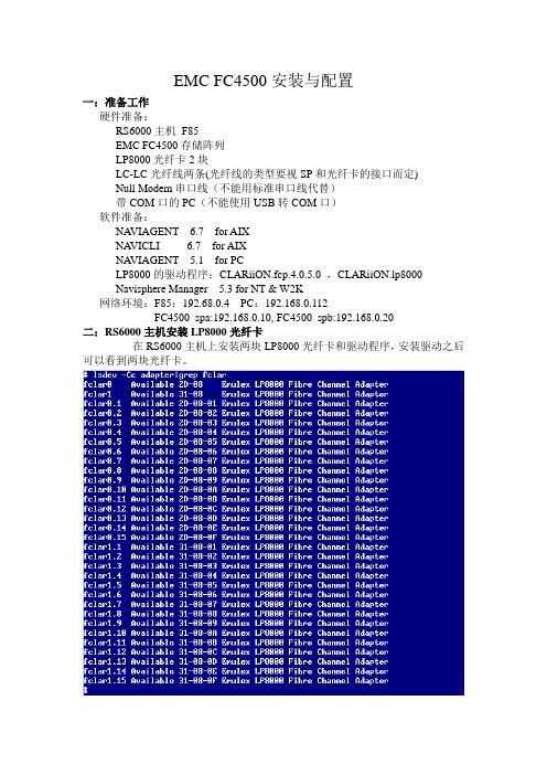
EMC FC4500安装与配置一:准备工作硬件准备:RS6000主机F85EMC FC4500存储阵列LP8000光纤卡2块LC-LC光纤线两条(光纤线的类型要视SP和光纤卡的接口而定)Null Modem串口线(不能用标准串口线代替)带COM口的PC(不能使用USB转COM口)软件准备:NA VIAGENT 6.7 for AIXNA VICLI 6.7 for AIXNA VIAGENT 5.1 for PCLP8000的驱动程序:CLARiiON.fcp.4.0.5.0 ,CLARiiON.lp8000Navisphere Manager 5.3 for NT & W2K网络环境:F85:192.68.0.4 PC:192.168.0.112FC4500_spa:192.168.0.10, FC4500_spb:192.168.0.20二:RS6000主机安装LP8000光纤卡在RS6000主机上安装两块LP8000光纤卡和驱动程序,安装驱动之后可以看到两块光纤卡。
三:FC4500的设置FC4500的一些基本参数例如IP地址,网关,TTY等是可以通过串口用超级终端来进行设置的。
用Null Modem串口线分别连接FC4500 SP上的COM口和PC的COM口,并把超级终端进行如下设置:点击确定,进行连接.进入EMC 的FCLI命令界面,如图所示:FCLI命令行有很多的基本命令可以用来显示,设置和修改FC4500的基本参数在这里我简单的介绍以下几个命令getlog命令# 获取sp的日志文件getwwn命令#获得串口所连接的SP光纤端口的WWN地址。
由于我们是用主机直接连接fc4500,所以可以不用理睬SP的WWN地址,但在连接光纤交换机并配置zoning 的时候,就需要获得SP光纤端口的WWN地址。
举例:fcli> getwwnCurrent NODE world wide name : 50.6.1.60.fb.17.23.cfCurrent PORT world wide name : 50.6.1.68.fd.17.23.cfsetcon/con 命令#set/display console TTY parameters举例:fcli> setconBaud Rate: 9600Parity: NONE举例:fcli> help setconUsage: setcon -hsetcon <options>options:-b <#> set the console baud rate. 1200/2400/4800/9600.19200 available on sauna only-d reset the console to the default values.-p <#> set the consol parity. 0/1/2 0-none, 1-odd, 2-evensetlan命令#显示并更改sp的lan信息举例:fcli> setlanLAN Configuration: SP B LOOP ID 0x0 (0.)Ethernet Address : 08:00:3e:2f:76:2aIP Address : 192.168.0.20Subnet Mask : 255.255.255.0Broadcast Address : 192.168.0.255Default Gateway : 192.168.0.1SP Host Name : fc4500_spbTrusted Host List: (Maximum 6 Hosts)1. IP Address : 192.168.0.112 Subnet Mask : 255.255.255.02. IP Address : 192.168.0.4 Subnet Mask : 255.255.255.0举例:fcli> help setlansetlan/sl - configure the lan settingsUsage: setlan -hsetlansetlan <options>options:-ip <IP address> IP address of this SP-subnet <subnet mask> Subnet mask of this SP-gateway <gateway address> Gateway address of this SP-broadcast <broadcast address> Broadcast address of this SP-hostname <host name> Host name of this SP-ath <IP address><subnet mask> Add a trusted host-dth <IP address> Delete a trusted hostls命令#Logical Unit Summary:fcli> lsRaid Dflt. UnitLUN Group Owner Type Capacity Cache State Frus--- ----- ----- ------ -------- ----- ------- ------------------0 0 SP-B RAID-5 1.0 GB RW- ENA 0 1 21 0 SP-B RAID-5 1.0 GB RW- ENA 0 1 22 0 SP-B RAID-5 1.0 GB RW- ENA 0 1 23 0 SP-A RAID-5 1.0 GB RW- RDY 0 1 24 0 SP-A RAID-5 100 MB RW- RDY 0 1 2setport命令# allow front end fiber ports to be enabled or disabledfcli> help setportUsage: setport -hsetport <options>options:-a <on/off> enable/disable port a-b <on/off> enable/disable port b四:EMC存储系统进行管理的两中方式从用户的角度来说, 存在两种界面对存储系统进行管理: CLI 和GUI。
DCS-4500_基本管理命令

目录第1章交换机基本配置命令.......................................................1-11.1 基本配置命令...................................................................................1-11.1.1 clock set................................................................................................1-11.1.2 config.....................................................................................................1-11.1.3 debug ssh-server..................................................................................1-11.1.4 enable....................................................................................................1-11.1.5 enable password...................................................................................1-21.1.6 exec-timeout..........................................................................................1-21.1.7 exit..........................................................................................................1-31.1.8 help........................................................................................................1-31.1.9 hostname...............................................................................................1-31.1.10 ip host..................................................................................................1-41.1.11 ipv6 host..............................................................................................1-41.1.12 ip http server.......................................................................................1-41.1.13 language..............................................................................................1-51.1.14 login.....................................................................................................1-51.1.15 login local............................................................................................1-51.1.16 password.............................................................................................1-61.1.17 reload...................................................................................................1-61.1.18 service password-encryption............................................................1-61.1.19 service terminal-length.......................................................................1-71.1.20 set default............................................................................................1-71.1.21 setup....................................................................................................1-71.1.22 show clock..........................................................................................1-81.1.23 show temperature...............................................................................1-81.1.24 show tech-support..............................................................................1-81.1.25 show version.......................................................................................1-81.1.26 username.............................................................................................1-81.1.27 web language......................................................................................1-91.1.28 web-user..............................................................................................1-91.1.29 write...................................................................................................1-101.2 远程管理........................................................................................1-101.2.1 authentication login............................................................................1-101.2.2 terminal length....................................................................................1-101.2.3 terminal monitor.................................................................................1-111.2.4 telnet....................................................................................................1-111.2.5 telnet-server enable............................................................................1-121.2.6 telnet-server securityip......................................................................1-121.2.7 telnet-server securityipv6..................................................................1-121.2.8 telnet-user...........................................................................................1-131.2.9 ssh-server authentication-retries......................................................1-131.2.10 ssh-server enable.............................................................................1-131.2.11 ssh-server host-key create rsa........................................................1-141.2.12 ssh-server timeout............................................................................1-141.2.13 ssh-user.............................................................................................1-141.2.14 show ssh-server................................................................................1-151.2.15 show ssh-user...................................................................................1-151.2.16 show telnet login...............................................................................1-151.2.17 show telnet user................................................................................1-16 1.3 配置交换机的IP地址.......................................................................1-161.3.1 interface vlan.......................................................................................1-161.3.2 interface ethernet................................................................................1-161.3.3 ip address............................................................................................1-161.3.4 ipv6 address........................................................................................1-171.3.5 ip bootp-client enable.........................................................................1-171.3.6 ip dhcp-client enable..........................................................................1-18 1.4 SNMP命令......................................................................................1-181.4.1 debug snmp mib.................................................................................1-181.4.2 debug snmp kernel.............................................................................1-181.4.3 rmon enable........................................................................................1-191.4.4 show snmp..........................................................................................1-191.4.5 show snmp engineid..........................................................................1-201.4.6 show snmp group...............................................................................1-211.4.7 show snmp mib...................................................................................1-211.4.8 show snmp status...............................................................................1-211.4.9 show snmp user.................................................................................1-221.4.10 show snmp view...............................................................................1-221.4.11 snmp-server community..................................................................1-231.4.12 snmp-server enable..........................................................................1-231.4.13 snmp-server enable traps................................................................1-231.4.14 snmp-server engineid.......................................................................1-241.4.15 snmp-server group...........................................................................1-241.4.16 snmp-server host..............................................................................1-251.4.17 snmp-server securityip....................................................................1-261.4.18 snmp-server securityip enable........................................................1-261.4.19 snmp-server view..............................................................................1-261.4.20 snmp-server user..............................................................................1-27 1.5 交换机升级命令..............................................................................1-281.5.1 copy(FTP).......................................................................................1-281.5.2 copy(TFTP).....................................................................................1-291.5.3 dir.........................................................................................................1-301.5.4 ftp-server enable.................................................................................1-301.5.5 ftp-server timeout...............................................................................1-311.5.6 ip ftp.....................................................................................................1-311.5.7 show ftp...............................................................................................1-311.5.8 show tftp..............................................................................................1-321.5.9 tftp-server enable................................................................................1-321.5.10 tftp-server retransmission-number.................................................1-321.5.11 tftp-server transmission-timeout.....................................................1-33第2章集群配置命令..................................................................2-12.1 clear cluster candidate table..........................................................2-12.2 cluser auto-add enable...................................................................2-12.3 cluster commander.........................................................................2-12.4 cluster heartbeat.............................................................................2-22.5 cluster holdtime..............................................................................2-22.6 cluster ip-pool.................................................................................2-32.7 cluster member...............................................................................2-32.8 cluser register timer.......................................................................2-42.9 cluster reset member.....................................................................2-42.10 cluster run.....................................................................................2-42.11 cluster update member.................................................................2-52.12 debug cluster application............................................................2-52.13 debug cluster packets..................................................................2-52.14 debug cluster statemach..............................................................2-62.15 rcommand commander................................................................2-62.16 rcommand member......................................................................2-62.17 show cluster..................................................................................2-72.18 show cluster candidates..............................................................2-72.19 show cluster members.................................................................2-7第1章 交换机基本配置命令1.1基本配置命令1.1.1 clock set命令:clock set <HH:MM:SS> <YYYY.MM.DD>功能:设置系统日期和时钟。
4500系列交换机白皮书
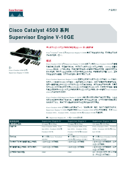
有 仅在非阻塞千兆位以太网端口 上支持 软件 1 无 直通式 有(需子卡) Cisco IOS ® 12.1(12c)EW 或更高版本 333 MHz 512 MB 4000 28,000 (第三层) , 16,000 (第 二层) 3000 4000 有(512 KB) 有(16 KB)
1 2
有 在所有端口上支持 硬件 2 有 在硬件中 有(需子卡) Cisco IOS® 12.2(18)EW 或 更高版本 400 MHz 512 MB 4000 28,000 (第三层) , 16,000 (第二层) 3000 4000 有(512 KB) 有(16 KB)
Cisco Catalyst 4500
Supervisor Engine V-10GE
在状态化切换(SSO)的支持下,管理引擎间实现信息同步化,在主管理引擎发生故障时,备用管 理引擎可立即在不到一秒的情况下接管所有运行。 无需重协商会话即可透明地保持第二层链路。 因 此,IP 话音(VoIP)呼叫等关键业务应用不会被丢弃。此外,还支持不间断转发(NSF)感知,能 与支持思科 NSF 的设备对接,且能在因管理引擎切换而更新路由信息的同时继续转发分组。 使用 Supervisoห้องสมุดไป่ตู้ Engine V-10GE 的冗余机制类似于 Supervisor Engine IV 和 V。如果任一管理引擎 发生故障,就会向网络监控软件生成报警。在不干扰系统运行的情况下,支持管理引擎的热插拔。 管理引擎的切换可由软件执行,或由用户通过简单网络管理协议(SNMP)执行。Cisco Catalyst 4500 系列的永续性特性可防止会损失业务和收入的网络中断。
!"
第二到四层性能 机箱支持
Supervisor Engine IV
Cisco Catalyst 4500 系列产品数据手册说明书
Data SheetCisco Catalyst 4500 SeriesCisco Catalyst 4500 Series integrates resiliency for advanced control of convergednetworks.Figure 1Cisco Catalyst 4503,4506, and 4507R SeriesOverviewThe Cisco Catalyst ® 4500 Series offers nonblocking Layer2/3/4 switching with integrated resiliency, further enhancing control of converged networks. Converged voice/video/data networks with high availability enable business resiliency forenterprise and metropolitan (metro) Ethernet customers deploying Internet-based business applications. A next-generation Cisco Catalyst 4000 Family platform, the Cisco Catalyst 4500 Series includes three new Cisco Catalyst chassis: Cisco Catalyst 4507R (seven slots),Cisco Catalyst 4506 (six slots), andCisco Catalyst 4503 (three slots). Integrated resiliency enhancements offeredin the Cisco Catalyst 4500 Seriesinclude 1 + 1 supervisor engine redundancy (Cisco Catalyst 4507R only), integrated inline power for IP telephony, software-based fault tolerance, and 1 + 1 power supply redundancy. Integrated resiliency in both hardware and softwareminimizes network downtime, ensuring workforce productivity, profitability, and customer success.As a key component of Cisco AVVID (Architecture for Voice, Video and Integrated Data), the Cisco Catalyst 4500 extends control to the network edge with intelligent network services, including sophisticated quality of service (QoS), predictable performance, advancedsecurity, comprehensive management, and integrated resiliency. Offering compatibility with Cisco Catalyst 4000 Family line cards and supervisor engines, the Cisco Catalyst 4500 Series enables an extended window of deployment for the Cisco Catalyst 4000 Family in converged networks. This reduces the cost of ownership by minimizing recurring operational expenses, thus improving return on investment (ROI). Cisco Catalyst 4500 Series ChassisThe Cisco Catalyst 4500 Series, with threechassis options and three supervisor engine options, provides a common architecture that scales to 240 ports of 10/100, 100BASE-FX Fast Ethernet, 1000BASE-LX, or 10/100/1000BASE-T Gigabit Ethernet. The Cisco Catalyst 4507R is the only Cisco Catalyst 4500 Series switch to support 1 + 1 redundant supervisor engines with sub-minute failovertime.Using the same line cards and supervisor engines (Supervisor Engines II and III) as the widely deployed Cisco Catalyst 4000 Series, the Cisco Catalyst 4500 Series enhances the Cisco commitment to affordable enterprise and branch scalability, providing a cost-effective, flexible network solution that scales to meet today’s high-performance needs with investment protection (refer to Table 1).Note:Supervisor engine slots do not support switching line-card modules; line-card slots do not support supervisorengines.Table 1Cisco Catalyst 4500 Series Chassis FeaturesFeatureChassis Chassis Chassis Total number of slots 367Supervisor engine slots 111.Slot 1 is reserved for supervisor engine only; slots 2 and higher are reserved for line cards.11222.Slots 1 and 2 are reserved for supervisor engines only in the Cisco Catalyst 4507R. Slots 3 and higher are reserved for line c ards.Supervisor engine redundancyNoNoYes (Supervisor Engine IV only)Supervisor engines supported Supervisor II Supervisor III Supervisor IVSupervisor II Supervisor III Supervisor IV Supervisor IVLine-card slots2552Number of power supply bays 222AC input power YesYesYesDC input powerYes (future)Yes (future)Yes (future)Integrated inline power (IP phone and wireless access point) supportYesYesYesMinimum number of power supplies111Number of fan-tray bays 111Location of 19-inch rack-mount FrontFrontFrontLocation of 23-inch rack-mountFront (option)Front (option)Front (option)Configuration AlternativesThe Cisco Catalyst 4500 Series offers a powerful and flexible network solution that can be built with three powerful supervisor engine alternatives. Each provides a high-performance, centralized, shared-memory switch fabric, while protecting your line-card investment by supporting the addition of optional higher-layer functionality engines (Table2).Note:For a detailed list of Cisco Catalyst 4000 Family Supervisor Engine III and IV features, refer to the Cisco Catalyst 4000 Family Supervisor Engine III and IV data sheet located on the Cisco Catalyst 4000 Family site: /warp/public/cc/pd/si/casi/ca4000/The Cisco Catalyst 4500 Series has flexible interface types and port densities that allow network configurations to be mixed and matched to meet the specific needs of any campus network (Table 3). Table 2Cisco Catalyst 4500 Series Supervisor Engine Support and PerformanceFeatureCisco Catalyst 4503 chassisSupported 24-Gbps engine, 18Mpps Supported 28Gbps, 21MppsSupported 28Gbps, 21MppsCisco Catalyst 4506 chassisSupported 24Gbps engine, 18Mpps Supported 64Gbps, 48Mpps Supported 64Gbps, 48MppsCisco Catalyst 4507R chassisNot supportedNot supportedSupported 64Gbps, 48MppsTable 3Cisco Catalyst 4500 Series Port Densities450345064507R Switched 10/100 FastEthernet (RJ-45)32 or 4896240240Switched 10/100 FastEthernet (RJ-21)4896240240Switched 100FastEthernet (MT-RJ) 4, 24, or 4896240240Switched 1000GigabitEthernet (fiber)2, 6, 18, or 4896240240Switched10/100/1000BASE-T Gigabit Ethernet12 (1000BASE-T only), 24 or 4896240240Configuration Flexibility and Modular SuperiorityThe Cisco Catalyst 4503, 4506, and 4507R offer the same comprehensive, scalable suite of 10/100/1000-Mbps Ethernet switch modules as the Cisco Catalyst 4003 and 4006. A variety of Cisco Catalyst 4000 Family modules areavailable, which can be mixed and matched to suit a wide range of wiring-closet, data-center, or branch-office deployments. Any Gigabit Ethernet port can be 1000BASE-SX, 1000BASE-LX/LH, 1000BASE-ZX, or coarse wavelength-division multiplexing (CWDM) by using flexible, hot-swappable gigabit-interface-converter (GBIC) modules. The Cisco Catalyst 4500 Series supports the following switching modules:•WS-X4148-FX-MT—Cisco Catalyst 4000 Fast Ethernet Switching Module, 48-port 100BASE-FX multimode fiber (MMF) (MT-RJ)•WS-X4148-RJ—Cisco Catalyst 4000 10/100 Module, 48 ports (RJ-45)•WS-X4148-RJ21—Cisco Catalyst 4000 10/100 Module, 48-port telco (4 x RJ-21)•WS-X4148-RJ45V—Cisco Catalyst 4000 Inline Power 10/100, 48 ports (RJ-45) for IP phones and wireless accesspoints•WS-X4232-GB-RJ—Cisco Catalyst 4000 32-Port 10/100 (RJ-45), 2-Gigabit Ethernet (GBIC) Module•WS-X4232-L31—Cisco Catalyst 4000 Layer 3 32-Port 10/100 (RJ-45), 2-Gigabit Ethernet (GBIC) Module •WS-X4232-RJ-XX—Cisco Catalyst 4000 Layer 3 Services 32-port 10/100 (RJ-45), plus modular uplink slot •WS-X4424-GB-RJ45—Cisco Catalyst 4000 24-Port 10/100/1000 Module (RJ-45)•WS-X4306-GB—Cisco Catalyst 4000 Gigabit Ethernet Module, 6 ports (GBIC)•WS-X4412-2GB-T—Cisco Catalyst 4000 Gigabit Ethernet Module, 12-port 1000BASE-T (RJ-45) + 2-port [1000BASE-X (GBIC)•WS-X4418-GB—Cisco Catalyst 4000 Gigabit Ethernet Module, server switching, 18 ports (GBIC)•WS-X4448-GB-LX—Cisco Catalyst 4000 48-port 1000BASE-LX (small form-factor pluggable [SFP])•WS-X4448-GB-RJ45—Cisco Catalyst 4000 48-port 10/100/1000 Module (RJ-45)•WS-U4504-FX-MT—Cisco Catalyst 4000 Fast Ethernet Uplink Daughter Card, 4-port 100BASE-FX (MT-RJ)•WS-X4604-GWY1—Cisco Catalyst 4000 Access Gateway Module with IP/firewall software•WS-X4095-PEM—Cisco Catalyst 4006 DC Power Entry Module•WS-X4124-FX-MT—Cisco Catalyst 4000 Fast Ethernet Switching Module, 24-port [100BASE-FX (MT-RJ)•WS-X40191—Cisco Catalyst 4000 Backplane Channel Module•WS-G54831—Cisco 1000BASE-T GBIC•WS-G5484—Cisco 1000BASE-SX Short-Wavelength GBIC (multimode only)•WS-G5486—Cisco 1000BASE-LX/LH Long-Haul GBIC (single mode or multimode)•WS-G5487—Cisco 1000BASE-ZX Extended-Reach GBIC (single mode)•Cisco CWDM GBIC solution1.Supported with Supervisor Engine II with Cisco Catalyst Operating System (CatOS) Version 7.4(1) and up at FCSSoftware RequirementsTable 4 gives requirements for the Cisco Catalyst Supervisor Engine Software, and Table 5 gives the differences between the Cisco Catalyst 4000 and 4500 Series switches.Standard Network Protocols •Ethernet–IEEE 802.3, 10BASE-T •Fast Ethernet–IEEE 802.3u, 100BASE-TX –IEEE 802.3, 100BASE-FXTable 4Cisco Catalyst Supervisor Engine Software Requirements SpecificationEngine IIMinimum software requirementCisco CatOS Software Version 7.4(1) or higherCisco IOS ® Software Version 12.1(12c)EW or higherCisco IOS Software Version 12.1(12c)EW or higherTable 5Key Differences Between Cisco Catalyst 4000 and 4500 SeriesFeature 40034006450345064507RInline powerNoYes—Withexternal power shelf Yes—IntegratedYes—IntegratedYes—IntegratedPower supply redundancy 1 + 1 2 + 11 + 1 1 + 1 1 + 1Supervisor engineredundancy No No No No YesSupported line cardsAll CiscoCatalyst 4000 line cards All CiscoCatalyst 4000 line cards All CiscoCatalyst 4000 line cards All CiscoCatalyst 4000 line cardsAll CiscoCatalyst 4000 switching line cards 11.WS-X4604-GWY will be supported in a future software release. WS-X4019 is not needed with Supervisor Engine IV.Supervisor engines supported Supervisor Engine ISupervisor Engines II, III, and IV Supervisor Engines II, III, and IV Supervisor Engines II, III, and IV Supervisor Engine IVPower supplies supported400-watt AC 400-watt DC400-watt AC 400-watt DC1000-watt AC 2800-watt ACV1000-watt AC 2800-watt ACV1000-watt AC 2800-watt ACV•Gigabit Ethernet–IEEE 802.3z–IEEE 802.3x–IEEE 802.3ab•1000BASE-X (GBIC)–1000BASE-SX–1000BASE-LX/LH–1000BASE-ZX•Virtual LAN (VLAN) trunking/tagging–IEEE 802.1Q•Spanning-Tree Protocol–IEEE 802.1D–IEEE 802.1w–IEEE 802.1s•Security–IEEE 802.1xNetwork Management•CiscoWorks Network Management Suite, Resource Manager Essentials support, including:–Inventory Manager–Change Audit–Device Configuration Manager–Software Image Manager–Availability Manager–Syslog Analyzer–Cisco Management Connection•CiscoWorks Network Management Suite, Campus Manager support, including:–Network topology discovery and display services–VLAN provisioning and logical display representation–Traffic monitoring and performance assessment–End-station tracking with search utilities–CiscoView graphical device management–Network topology integrity checking–Cisco Discovery Protocol–Cisco Virtual Trunking Protocol (VTP)–Simple Network Management Protocol (SNMP) agent Version 1 (RFCs 1155–1157)–SNMP Version 2c–Cisco Workgroup Management Information Base (MIB)–Ethernet MIB (RFC 1643)–Ethernet Repeater MIB (RFC 1516)–SNMP MIB II (RFC 1213)–Remote Monitoring (RMON) (RFC 1757)–Remote Monitoring II (RMON II) (RFC 2021)–Interface Table (RFC 1573)–Bridge MIB (RFC 1493)–Switched Port Analyzer (SPAN)–Enhanced Switched Port Analyzer (ESPAN)–Port snooping and connection steering–Text-based command-line interface (CLI) based on the familiar Cisco Catalyst 5000 Series interface (Supervisor Engine II only)–Standard Cisco IOS security capabilities: passwords and TACACS+–Telnet, Trivial File Transfer Protocol (TFTP), BOOTP for management access Physical SpecificationsTable 6 gives the physical specifications of the Cisco Catalyst 4500 Series chassis, and Table 7 gives Cisco Catalyst 4500 power supply specifications.Power Supply Indicators and Interfaces•Fan cooling: Integrated in hot-insertion/hot-extraction unit •Good: Green (good)•Fail: Red (faulty)•SNMP MIB supportedTable 6Physical Specifications of Cisco Catalyst 4500 SeriesChassisDimensions (H x W x D):(12.25 x 17.31 x 12.50 in.), (31.12 x 43.97 x 31.70 cm)(17.38 x 17.31 x 12.50 in.), (44.13 x 43.97 x 31.70 cm)(19.19 x 17.31 x 12.50 in.), (48.74 x 43.97 x 31.70 cm)Rack units 7 rack units high 10 rack units high 11 rack units high Minimum weight:52 lb 56 lb 57 lb Maximum weight:75 lb100 lb107 lbMounting:19- and 23-in. rackcompatible (19-in. rack and cable guide hardware included)19- and 23-in. rackcompatible (19-in. rack and cable guide hardware included)19- and 23-in. rackcompatible (19-in. rack and cable guide hardware included)Fan TraysEach Cisco Catalyst 4500 chassis uses a single fan tray for cooling. All fan trays are composed of independent fans. If one fan fails, the system will continue to operate without a significant degradation in cooling. The system will detect and notify the user (via LED, CLI, and SNMP) that a fan has failed and the tray needs to be replaced.Fabric Redundancy Modules (Cisco Catalyst 4507R only)The Cisco Catalyst 4507R redundancy scheme uses removable fabric redundancy modules on the passive backplane to switch traffic to the active supervisor. There is one fabric redundancy module per line card, for a total of five modules per chassis. All five fabric redundancy modules ship standard with every Cisco Catalyst 4507R chassis. The Cisco Catalyst 4507R also ships standard with redundant clocks. Spare fabric redundancy modules and clock modules are available for serviceability.Table 7Cisco Catalyst 4500 Power Supply SpecificationsIntegrated voice (48V inline power)No (data only)Yes (up to 1400 watts)Input current•13.2A maximum @ 100VAC • 6.6A maximum @ 200VAC•17.6A maximum @ 200VACAC Input Power Requirements•100–240V~•50/60 Hz •12–5A•220–240V~•50/60 Hz •16AOutput current (data)*********************************Output current (voice)n/a ****************KVA rating1.32 KVA3.52 KVAOutput power (data)1000W + 40W (fan)1360W + 40W (fan)Output power (voice)n/a1400W per power supply Heat dissipation 943 BTU/hr 2387 BTU/hr Holdup time20 ms 20 ms Cisco phones supported with integrated inline powerNoneUp to 24011.240 phones are supported in power supply combined mode. Refer to the Cisco Catalyst 4500 IP Telephony white paper at the following URL for details on phonesupport.Place url here Note:1.Output power is per power supply, but total output power from two supplies is not twice the output of one power supply. See the specifications.2.Heat dissipation numbers represent the power conversion losses of the power supply in operation.Environmental Conditions•Operating temperature: 32º to 104ºF (0º to 40ºC)•Storage temperature: –40º to 167ºF (–40º to 75ºC)•Relative humidity: 10 to 90%, noncondensing•Operating altitude: –60 to 4000 mRegulatory Standards ComplianceTable 8 gives information regarding compliance of the Cisco Catalyst 4500 Series to regulatory standards. Table 8Regulatory Standards Compliance of Cisco Catalyst 4500 SeriesRegulatory compliance CE markingSafety•UL 60950•CAN/CSA-C22.2 No. 60950•EN 60950•IEC 60950•TS 001•AS/NZS 3260EMC•FCC Part 15 (CFR 47) Class A•ICES-003 Class A•EN55022 Class A•CISPR22 Class A•AS/NZS 3548 Class A•VCCI Class A•EN 55022•EN 55024•EN 61000-6-1•EN 50082-1•EN 61000-3-2•EN 61000-3-3•ETS 300 386Industry EMC, safety, and environmental standards •GR-63-Core Network Equipment Building Standards (NEBS) Level 3•GR-1089-Core Level 3•ETS 300 019 Storage Class 1.1•ETS 300 019 Transportation Class 2.3 (pending)•ETS 300 019 Stationary Use Class 3.1•ETS 300 386Telecom (E1)•CTR 12/13•CTR 4•ACA TS016Telecom (T1)•FCC Part 68•Canada CS-03•JATE Green BookOrdering InformationTable 9 lists Cisco Catalyst 4500 common equipment ordering information details.Table 9Cisco Catalyst 4500 Common Equipment Ordering InformationWS-C4503Cisco Catalyst 4500 (3-slot chassis), fan, nopower supplyWS-C4506Cisco Catalyst 4500 (6-slot chassis), fan, nopower supplyWS-C4507R Cisco Catalyst 4500 (7-slot chassis), fan, nopower supply, redundant supervisor capable PWR-C45-1000AC Cisco Catalyst 4500 1000-watt AC power supply (data only)PWR-C45-2800ACV Cisco Catalyst 4500 2800-watt AC power supply (with integrated voice)WS-X4013Cisco Catalyst 4000 Family Supervisor Engine IIWS-X4014Cisco Catalyst 4000 Family Supervisor Engine IIIWS-X4515Cisco Catalyst 4000 Family Supervisor Engine IVWS-X4515/2Cisco Catalyst 4507R Series Redundant Supervisor Engine IVS4KL3-12112EW Cisco IOS Software for the Cisco Catalyst 4000 Family Supervisor Engines III and IV; basic Layer 3 software image (Routing Information Protocol [RIP], static routes, IPX, AppleTalk)S4KL3E-12112EW Cisco IOS Software for the Cisco Catalyst 4000 Family Supervisor Engines III and IV;enhanced Layer 3 software image, including Open Shortest (OSPF), Interior GatewayRouting Protocol (IGRP), and Enhanced IGRP (EIGRP)MEM-C4K-FLD64M Cisco Catalyst 4000 Family compact Flash memory for Supervisor III or IV, 64-MB option MEM-C4K-FLD128M Cisco Catalyst 4000 Family compact Flash memory for Supervisor III or IV, 128-MB optionLicensingUse of RMON on the Cisco Catalyst 4500 Series switches requires the purchase of the RMON agent license. Use of Border Gateway Protocol Version 4 (BGP4) on the Supervisor Engine III or IV requires an InterDomain Routing license. Only one RMON agent license or InterDomain Routing license is required per chassis.WS-C4503-EMS-LIC(=)Cisco Catalyst 4503 RMON Agent LicenseWS-C4506-EMS-LIC(=)Cisco Catalyst 4506 RMON Agent LicenseWS-C4507R-EMS-LIC(=)Cisco Catalyst 4507R RMON Agent LicenseFR-IRC4(=)Cisco Catalyst 4000 Supervisor III and IV InterDomain Routing Feature LicenseWarrantyThe warranty for the Cisco Catalyst 4500 Series is 90 days; it includes hardware replacement with a 10-day turnaround from return to manufacturer authorization (RMA).Service and SupportCisco offers life-cycle service and support for the Cisco Catalyst 4000 Family (including Cisco Catalyst 4000 and 4500 Series) directly and for resale through Cisco distributors. From implementation to operation and optimization, Cisco offers advanced service and technical support services.Advanced ServiceTotal Implementation Solutions (TIS) offers a full range of implementation solutions, including project management, project engineering, configuration, staging and rollout coordination, and ensuring correct installation, anddeployment. For more information on TIS, visit:/warp/public/cc/serv/mkt/sup/ent/tis/.Technical Support ServicesCisco SMARTnet® support augments the resources of your operations staff by providing them with access to a wealth of expertise, both online and via telephone, including the ability to refresh their system software at will, anda range of hardware Advance Replacement options. Cisco SMARTnet Onsite support provides all services andcomplements the hardware Advance Replacement feature by adding the services of a field engineer, services that can be critical for those locations where staffing is insufficient or unavailable to perform parts replacement activities. For more information on Cisco SMARTnet support, visit:/warp/public/cc/serv/mkt/sup/ent/snet/.For additional information on Cisco products, contact:United States and Canada: 800 553-NETS (6387)Europe: 32 2 778 4242Australia: 612 9935 4107Other: 408 526-7209Cisco Systems, Inc.All contents are Copyright © 1992–2002 Cisco Systems, Inc. All rights reserved. Important Notices and Privacy Statement.Page 11 of 12Corporate Headquarters Cisco Systems, Inc.170 West Tasman Drive San Jose, CA 95134-1706 USATel:408 526-4000800 553-NETS (6387) Fax:408 526-4100European HeadquartersCisco Systems International BVHaarlerbergparkHaarlerbergweg 13-191101 CH AmsterdamThe NetherlandsTel:31 0 20 357 1000Fax:31 0 20 357 1100Americas HeadquartersCisco Systems, Inc.170 West Tasman DriveSan Jose, CA 95134-1706USATel:408 526-7660Fax:408 527-0883Asia Pacific HeadquartersCisco Systems, Inc.Capital Tower168 Robinson Road#22-01 to #29-01Singapore 068912Tel:+65 317 7777Fax:+65 317 7799Cisco Systems has more than 200 offices in the following countries and regions. Addresses, phone numbers, and fax numbers are listed on theC i s c o W e b s i t e a t w w w.c i s c o.c o m/g o/o f f i c e sArgentina • Australia • Austria • Belgium • Brazil • Bulgaria • Canada • Chile • China PRC • Colombia • Costa Rica • Croatia CzechRepublic • Denmark • Dubai, UAE • Finland • France • Germany • Greece • Hong Kong SAR • Hungary • India • Indonesia • Ireland Israel • Italy • Japan • Korea • Luxembourg • Malaysia • Mexico • TheNetherlands • New Zealand • Norway • Peru • Philippines • P oland Portugal • Puerto Rico • Romania • Russia • Saudi Arabia • Scotland • Singapore • Slovakia • Slovenia • South Africa • Spain • S weden Switzerland • Taiwan • Thailand • Turkey • Ukraine • United Kingdom • United States • Venezuela • Vietnam • Zimbabwe All contents are Copyright © 1992–2002, Cisco Systems, Inc. All rights reserved. SMARTnet is a trademark, and Catalyst, Cisco, Cisco IOS, Cisco Systems, and the Cisco Systems logo are registered trademarks of Cisco Systems, Inc. and/or its affiliates in the U.S. and certain other countries.All other trademarks mentioned in this document or Web site are the property of their respective owners. The use of the word partner does not imply a partnership relationship between Cisco and any other company. (0206R)LW33760802。
DCS安装和网络配置
第一章软件安装和网络配置1. 概述XDPS软件分MMI软件、GTW软件和DPU软件。
升级安装时,最好先读一下第一张安装盘上的Update.txt文件,以获取有关升级的注意事项的信息。
1.1 MMI软件安装MMI软件可安装于任何能运行Windows 95/98/NT的计算机上。
一般采用工业PC或工作站,典型采用Pentium 200MHZ以上的CPU,内存要求大于等于16M,典型为64M。
MMI软件内容有网络驱动、实时数据库、MMI应用软件、VDPU软件、DPU软件影像和样例数据文件。
安装完成后,须进行网络配置和MMI应用配置,才能正常运行MMI软件。
本节只讲述MMI的安装和配置。
1.2 GTW软件安装GTW软件的运行在MMI软件之上。
GTW软件必须在安装好MMI软件后,单独安装,安装方法和内容请参见具体GTW软件的说明。
1.3 DPU软件安装DPU软件的安装和内容请参见本手册“DPU及VDPU软件”一节。
2. MMI软件的安装XDPS MMI软件是打包安装的,安装前应退出全部其它的应用程序。
安装通过向导进行,运行安装盘中的Setup.exe后,进入安装向导:先让用户选择安装目录,用户可指定任意的Windows有效目录,不存在的目录,向导会为您生成(如上右图)。
但一般采用缺省的D:\xdps2.0目录。
按“Next”继续。
右图对话框让您选择要安装的部件,列表中依次为项目数据样例文件、MMI软件、VDPU软件和DPU软件影象文件。
点击列表项,您选择/不选择该项。
一般初次安装,应选前三项,升级安装选中间二项。
最后一项,用于DPU软件的在线升级,一般只安装于工程师站上,具体说明,请参见本手册“DPU及VDPU软件”一节。
按“Next”继续;右图对话框让您选择将生成的Windows程序组名,并将出现在“开始”菜单中。
再按“Next”,就进入实质性安装。
完成后,按“Finish”结束。
安装后,在安装目录下,生成了X2bin和X2data目录,分别存放软件的执行文件和项目数据文件。
思科 Catalyst 4500 E 系列管理引擎 8L-E 安装和配置指南说明书
Cisco Catalyst 4500 E 系列管理引擎 8L-E 安装和配置说明首次发布日期: 2016年03月11日Cisco Catalyst 4500 E 系列管理引擎 8L-E 安装和配置说明产品编号:WS-X45-Sup8L-E本指南介绍如何安装Catalyst4500E系列管理引擎8L-E。
有关管理引擎和交换模块的配置信息,请参阅交换机的软件配置指南。
注意:Catalyst4500E系列交换模块需要使用E系列管理引擎,该管理引擎应运行与其兼容的软件映像。
有关兼容性的信息,请参阅交换机的版本说明注释表 1:管理引擎 8L-E 的机箱兼容性信息1Cisco Catalyst 4507R-E 交换机仅在硬件版本为2.0或更高版本的机箱上支持管理引擎8L-E 。
安全警告在本指南中,凡是操作不当会导致人身伤害的操作程序都会注明安全警告。
每个警告声明前面都有一个警告符号。
以下警告是适用于整个指南的常规警告。
声明 1071 - 警告的定义重要安全性说明此警告符号表示存在危险。
您目前所处情形有可能遭受身体伤害。
在操作任何设备之前,请务必意识到触电危险并熟悉标准工作程序,以免发生事故。
请根据每个警告结尾处的声明号来查找此设备随附的安全警告的翻译文本。
声明1071请妥善保存这些说明警告BELANGRIJKE VEILIGHEIDSINSTRUCTIESDit waarschuwingssymbool betekent gevaar.U verkeert in een situatie die lichamelijkletsel kan veroorzaken.Voordat u aan enige apparatuur gaat werken,dient u zichbewust te zijn van de bij elektrische schakelingen betrokken risico's en dient u opde hoogte te zijn van de standaard praktijken om ongelukken te voorkomen.Gebruikhet nummer van de verklaring onderaan de waarschuwing als u een vertaling vande waarschuwing die bij het apparaat wordt geleverd,wilt raadplegen.BEWAAR DEZE INSTRUCTIESWaarschuwing TÄRKEITÄTURV ALLISUUSOHJEITATämävaroitusmerkki merkitsee vaaraa.Tilanne voi aiheuttaa ruumiillisia vammoja.Ennen kuin käsittelet laitteistoa,huomioi sähköpiirien käsittelemiseen liittyvät riskitja tutustu onnettomuuksien yleisiin ehkäisytapoihin.Turvallisuusvaroitustenkäännökset löytyvät laitteen mukana toimitettujen käännettyjenturvallisuusvaroitusten joukosta varoitusten lopussa näkyvien lausuntonumeroidenavulla.SÄILYTÄNÄMÄOHJEETVaroitus IMPORTANTES INFORMATIONS DE SÉCURITÉCe symbole d'avertissement indique un danger.Vous vous trouvez dans une situationpouvant entraîner des blessures ou des dommages corporels.Avant de travaillersur un équipement,soyez conscient des dangers liés aux circuits électriques etfamiliarisez-vous avec les procédures couramment utilisées pour éviter les accidents.Pour prendre connaissance des traductions des avertissements figurant dans lesconsignes de sécuritétraduites qui accompagnent cet appareil,référez-vous aunuméro de l'instruction situéàla fin de chaque avertissement.CONSERVEZ CES INFORMATIONSAttention Cisco Catalyst 4500 E 系列管理引擎 8L-E 安装和配置说明安全警告WICHTIGE SICHERHEITSHINWEISEDieses Warnsymbol bedeutet Gefahr.Sie befinden sich in einer Situation,die zuVerletzungen führen kann.Machen Sie sich vor der Arbeit mit Geräten mit denGefahren elektrischer Schaltungen und den üblichen Verfahren zur Vorbeugungvor Unfällen vertraut.Suchen Sie mit der am Ende jeder Warnung angegebenenAnweisungsnummer nach der jeweiligen Übersetzung in den übersetztenSicherheitshinweisen,die zusammen mit diesem Gerät ausgeliefert wurden.BEWAHREN SIE DIESE HINWEISE GUT AUF.Warnung IMPORTANTI ISTRUZIONI SULLA SICUREZZAQuesto simbolo di avvertenza indica un situazione potrebbe causareinfortuni alle persone.Prima di intervenire su qualsiasi apparecchiatura,occorreessere al corrente dei pericoli relativi ai circuiti elettrici e conoscere le procedurestandard per la prevenzione di incidenti.Utilizzare il numero di istruzione presentealla fine di ciascuna avvertenza per individuare le traduzioni delle avvertenzeriportate in questo documento.CONSERV ARE QUESTE ISTRUZIONIAvvertenza VIKTIGE SIKKERHETSINSTRUKSJONERDette advarselssymbolet betyr fare.Du er i en situasjon som kan føre til skade påperson.Før du begynner åarbeide med noe av utstyret,mådu være oppmerksompåfarene forbundet med elektriske kretser,og kjenne til standardprosedyrer for åforhindre ulykker.Bruk nummeret i slutten av hver advarsel for åfinne oversettelseni de oversatte sikkerhetsadvarslene som fulgte med denne enheten.TA V ARE PÅDISSE INSTRUKSJONENEAdvarsel INSTRUÇÕES IMPORTANTES DE SEGURANÇA .Este símbolo de aviso significa perigo.Vocêestáem uma situação que poderásercausadora de lesões corporais.Antes de iniciar a utilização de qualquer equipamento,tenha conhecimento dos perigos envolvidos no manuseio de circuitos elétricos efamiliarize-se com as práticas habituais de prevenção de acidentes.Utilize o númeroda instrução fornecido ao final de cada aviso para localizar sua tradução nos avisosde segurança traduzidos que acompanham este dispositivoGUARDE ESTAS INSTRUÇÕESAviso INSTRUCCIONES IMPORTANTES DE SEGURIDADEste símbolo de aviso indica peligro.Existe riesgo para su integridad física.Antesde manipular cualquier equipo,considere los riesgos de la corriente eléctrica yfamiliarícese con los procedimientos estándar de prevención de accidentes.Al finalde cada advertencia encontraráel número que le ayudaráa encontrar el textotraducido en el apartado de traducciones que acompaña a este dispositivo.GUARDE ESTAS INSTRUCCIONES¡Advertencia!Cisco Catalyst 4500 E 系列管理引擎 8L-E 安装和配置说明声明 1071 - 警告的定义VIKTIGA SÄKERHETSANVISNINGARDenna varningssignal signalerar fara.Du befinner dig i en situation som kan ledatill personskada.Innan du utför arbete pånågon utrustning måste du vara medvetenom farorna med elkretsar och känna till vanliga förfaranden för att förebyggaolyckor.Använd det nummer som finns i slutet av varje varning för att hitta dessöversättning i de översatta säkerhetsvarningar som medföljer denna anordning.SPARA DESSA ANVISNINGARVarning!Cisco Catalyst 4500 E 系列管理引擎 8L-E 安装和配置说明声明 1071 - 警告的定义Cisco Catalyst 4500 E 系列管理引擎 8L-E 安装和配置说明管理引擎 8L-E 的特性管理引擎 8L-E 的特性下图显示标有主要特性的管理引擎8L-E前视图。
7楼DCN-4500外网(楼层交换机)

loopback-detection control shutdown
!
Interface Ethernet1/2
loopback-detection specified-vlan 1
loopback-detection control shutdown
ip address 192.168.2.71 255.255.255.0
!
ip default-gateway 192.168.2.1
!
!
no login
!
!
end
loopback-detection control shutdown
!
Interface Ethernet1/5
loopback-detection specified-vlan 1
loopback-detection control shutdown
!
Interface Ethernet1/6
!
Interface Ethernet1/8
loopback-detection specified-vlan 1
loopback-detection control shutdown
!
Interface Ethernet1/9
loopback-detection specified-vlan 1
!
Interface Ethernet1/3
loopback-detection specified-vlan 1
loopback-detection control shutdown
DCS-4500系列全千兆智能安全接入交换机彩页
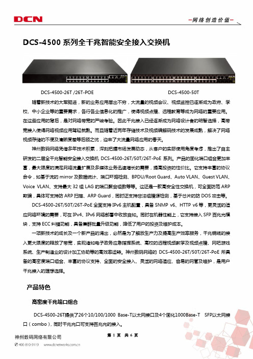
DCS-4500系列全千兆智能安全接入交换机DCS-4500-26T /26T-POE DCS-4500-50T 随着新技术的大军挺进,新的业务应用层出不穷,大流量的视频会议、视频监控已逐渐成为政府、学校、中小企业等的重要需求,各行各业信息化的推广,使得视频点播、远程教育等成为网络的重要应用。
在这些应用的背后,是对网络带宽的严峻考验。
因此千兆接入已经逐渐成为网络设计者的明智选择,高带宽接入使得网络视频应用驾轻就熟。
而且随着近两年存储技术及视频编解码技术的发展成熟,解决了网络视频存储的不便及清晰度差等后顾之忧,迎来了大流量网络应用的春天。
神州数码网络凭借多年技术积累,深刻把握市场发展动态,从客户的实际使用角度考虑,推出了自主研发的二层全千兆智能安全接入交换机DCS-4500-26T/50T/26T-PoE系列。
产品的固化端口组合更加丰富,最大限度的满足网络流量扩展及多媒体业务迅速增长的需要,提高投资的性价比。
它支持丰富的协议命令,如基于流的mirror及数据统计、端口环路检测、BPDU/Root Guard、Auto VLAN、Guest VLAN、Voice VLAN、支持最大32组LAG的端口聚合组数等等。
这还是一款高安全性交换机,可全面防范ARP 欺骗,具体可支持防ARP扫描、ARP Guard,同时还支持非法组播源检测,基于芯片的防DOS攻击等。
DCS-4500-26T/50T/26T-PoE全面支持IPv6主机配置,具备SNMP v6、HTTP v6等,更灵活的适应网络环境的需要,可在IPv4、IPv6网络部署中收放自如。
同时在机器性能上,它支持接入SFP百兆光模块,支持ECC纠错功能,具备集群批量升级功能,降低了用户的投资及维护成本。
一项新技术的成长及一个新产品的涌出,必然是为了解放生产力及提高生产效率服务,千兆铜缆的接入更大限度的释放了带宽,实现诸如电子政务应急指挥系统、高校的远程视频教学及视频点播、网吧游戏系统、生产制造业的设计加工协助等的高效率运转。
简易访问4500系列轻型商业杠杆锁安装指南说明书

14500 SERIES LIGHT DUTY COMMERCIAL LEVERFour AA BatteriesPhillips ScrewdriverUtility KnifeAdhesive TapePencilTape MeasurePower DrillWith ⅜“ (10mm) Drill BitHammer/Mallet and Chisel (1”)If your latch plate needs additional depth.Bolt CuttersIf the pre-cut mounting bolts do not fit your door.What’s in the box?Interior Lock Exterior Lock2 Lever HandlesStrike PlateSpindle2 ⅜“ (60mm) and2 ¾” (70mm) latch2 Rubber Gaskets 2 KeysSupport Post Storeroom Tailpiece(Optional)Hardware SetLet’s make sure you have everything you need. If you’re missing anything, contact************************.First things first, let’s get your new lock installed.Get connected.Use the Connection Guide to getyour lock online and registered.Take control.Now your lock is fully functional andcan be managed from anywhere.23Position the template. Array STEP 1This guide assumes the door is already prepped with a 2 ⅜“ boring hole.Use the provided drilling template to mark the upper ⅜” (10mm) support hole and prepare the door for drilling. Crease the template along the dotted lines matchingthe backset for your door (2 ⅜” (60mm) or 2 ¾” (70mm)latch).View the template from the other side of the door to make sure the dotted latch line on the template is exactly centered within the boring hole opening.Once the template is aligned, tape the template in place.Mark carefully. Array STEP 2Mark the center of the upper, ⅜” (10mm) hole to be drilled using a sharp object, like a nail or a thumbtack. After marking the exterior of the door, apply the template to the interior of the door using the same methods. Make sure the holes are aligned exactly from one side of the door to the other and double check all the measurements and markings to ensure precision. Mark the center of the ⅜” (10mm) hole to be drilled fromthe other side of the door.STEP 3Drill holes.Prepare your power drill with a ⅜” (10mm) drill bit.Align the drill bit over your mark and hold the door steady. Keep the drill level and straight.Drill halfway through on the first side. Then drill the remaining half from the other side of the door. This prevents blowback damage to the door and improves accuracy.Exterior of Door Interior of DoorSince the 2 ⅛“ (54mm) boring hole already exists in this example, the lower support bolt will go through the boring hole. Only the upper 10mm hole will need to be drilled. If your door is prepped with a smaller boring hole, use the template to drill the additional lower ⅜“ support.Quick TipDoors are typically prepped with either a 2 ⅜” (60mm)or 2 ¾” (70mm) inch backset. Latches are provided foreither option.This installation will be pictured with the standard 2 ⅜”(60mm) latch. Insert the latch in the door, making surethe beveled side faces the door jamb.Exterior of DoorUse the provided screws to secure the latch in place.Quick TipMake sure the latch plate lays flush with the door. If the latch plate isnot flush in the door, draw an outline around the faceplate edge andchisel a rebate to allow the latch to lay flush with the door edge.exterior (keypad side) of the door. The spring ensures thatthe spindle remains in contact with the front of the lock.Quick TipMake sure the spindle’s spring is on the exterior side of the door.If you install the spindle with the spring on the interior side of thedoor, the lock will not work properly.STEP 6Attach the latch support post.Next, attach the latch support post to the lock. This post will be screwed into either the left or right of the center hub. The hole that you will use depends on whether your door is a left-hand or right-hand door and which size latch is used.View your latch from the exterior side of the door to determine which support post position to use, thenscrew the post into the lock.When using the 2⅜“ latch, use the inner holes closest to the center hub. If using the 2 ¾“ latch, use the outer holes. Quick TipSTEP 7Attach the gaskets.Fit the self-adhesive gaskets on the backplate of each side of the lock.Peel the white backing off the gasket and apply to the backplate of the lock. Be sure to align the edges and pull the antenna and power cable through the appropriatehole, as shown.You will see your lock’s serial and model number on the sticker on the back of the lock. Write it down or take a picture for your records. This number is needed during online registration after installation. You will also find this sticker on the lock’s box.Quick TipSTEP 8Prepare the interior lock.Remove the screw that secures the battery cover and lift the plastic cover off of the lock.Next, remove the battery pack and set them both aside.STEP 9 Measure door depth. It’s vital to use the correct mounting bolts for your door’s thickness. Two sets of different sized bolts are provided, as well as a set of bolts with cut points that can be cut to size if needed.Place one of the bolts through the mounting bolt hole on the upper, battery pack side of the lock.Hold the lock flush with the door but allow the bolt to pass along the edge of the door to gauge its length.The correct bolt should go about a ½“ past the edge of the door.½“Optional StepIf neither of the two pre-cut bolt lengths work for your door, you will need to cut the fixing bolts to the correct length. Using the same method, align the bolt along the side of the door and choose a cutting pointapproximately ½“ beyond the edge of the door.Always cut the bolts at one of the cutting points so as not to damage a thread. Use the cutting edges of pliers to crimp around the selected cutting point. If the cut produces a sharp point, use sandpaper to smooth the tip of the bolt.Quick Tip Cutting Points and Door DepthThe exterior (keypad) side of the lock has two important cables sticking out of its backplate; a power cable and a Wi-Fi antenna cable.Pass the antenna and power cable over the latch. Align the support post through the hole in the latch, andmake sure the spindle fits snugly in the lock’s hub .IMPORTANT: Be sure to pass the power cable and antenna over the latch in the door, not under.Feed the power cable and the antenna through the hole above the main spindle hole.Once the cords are inside the lock, pull them up and outof the battery pack housing.With the power cable and antenna cable coming through the lock housing, make sure the lock is level and straight.Place the fixing bolts through the interior lock mounting holes and then tighten into the front side of the lock.Both screws are needed: one at the top of the lock (through the drilled hole) and one on the bottom of thelock (below the handle going through the boring hole).Leave the top screw somewhat loose before screwing in the bottom screw. Tighten both screw back and forth until snug.Do not over tighten.Quick TipNow that the lock is mounted to the door, make sure that the lever and the latch move freely.Turn the inside handle boss to check that the spindle moves freely and the latch retracts and projects smoothly.If the lock was secured too tightly to the door, you may find that the spindle or latch sticks. To correct this, loosen the fixing bolts and adjust the position of bothsides of the lock until the spindle moves freely.Connect battery pack. Array STEP 14Insert four AA batteries (not included) into the battery pack.Connect the power cable from the lock to the battery pack by connecting the two plugs. You should hear andfeel a click when the cables connect.Position power cord. Array STEP 15Push the power plug down and to the side of the lock housing, along with the wires. This provides room for thebattery pack and the battery cover.STEP 16Insert battery pack and connect antenna.Now slide the battery pack back into the lock housing with the top wires facing out.Connect the gold Wi-Fi antenna to the battery coverplate by clicking it in place.Plug the antenna into the connector as you would plug in headphones. The connector will plug in, rather than screw in.Quick TipAttach the battery cover. STEP 17 ArraySlide the battery cover back onto the lock interior andscrew it in.Quick TipPosition the battery cover just above the lock and then slide straight down into place.Place the key cylinder cover over the key cylinder located on the exterior (keypad side) of the e the provided Allen key to loosen the small screw on the appropriate handle. The handle should point away from the latch toward the hinges.Slide the handle over the handle boss and tighten the handle screw with the Allen key.Use the provided Allen key to loosen the small screw on the other handle.Slide the handle over the handle boss and tighten the handle screw with the Allen key.Turning the interior handle should retract the latch bolt.the latch.Enter the factory default code 4321 on the keypad to unlock the lock.The keypad will flash green and the outside handle will now retract the latch. Auto lock is enabled and the lock will re-lock after 5 seconds. These settings can be configured in the portal after connecting your lock to Wi-Fi.To lock the lock, press the * button twice.PLEASE NOTE:4321 will be disabled once an additional code is added to the lock.STEP 20Test your lock.Using your lock. LockingLock the door by pressing * * on the keypad.UnlockingUnlock the door by entering a user code.Once your lock is installed and connected to Wi-Fi, you can easily control your lock, add and manage access codes with the SimpleAccess app.For a complete list of manual programming options, visit .Programming Code:User Code: 4321Auto-Lock: EnabledAuto-Lock Delay: 5 SecondsKeypad Sound: EnabledHeartbeat Interval: 1 HourCard Reader: Off (Enable with 381 or 382 function) Default SettingsBy default, and after a factory reset, your lock has the following settings:MIFARE ReaderFunctionalityThis lock is equipped with a MIFARE card reader, enabling MIFARE cards, fobs and sticky tags to be used to unlock the door. MIFARE cards will need to be enrolled in your account first and then can be assigned to access users.Visit for instructions on enrolling cards.Enabling Card ReaderThe card reader is disabled by factory default. Enabling the card reader function can either be done on the lock’s settings page after registering with your SimpleAccess account, or on the keypad with the following key commands.Enable Card/Fob Reader (Always On)Enter your(123456 by default) followedby the # button,followed by #.Enable Card/Fob Reader on Button Press Only This function turns on the card/fob reader on the lock only after a button press. This saves a bit more power than using the Always On 381 function.Enter your (123456 by default) followed by the # button,followed by #.381382Using the Card ReaderAfter adding an access user to the lock with a MIFARE credential, the credential can be used to unlock the door. This is done by holding the MIFARE credential up to the keypad of the lock.For best results, hold the card or fob in the center of the keypad (over the 5 key) within an inch of the surface.If your card or fob is not registered on the first attempt,pull your hand away momentarily and then present again.Programming Functions The keypad can be used to program lock functions. These functions can also be performed remotely from the SimpleAccess app. None of the following functions are required for setup.All keypad programming functions follow the same general steps:1. Enter your followed by the # button.2. Enter the for the desired function,followed by the # button.3. Some functions will also require you to enter afollowed by the # button.Function CodesPLEASE NOTE: Most of these settings can be updated online in the portal. After installing and connecting your lock to Wi-Fi, please register your lock and configure settings at 100: Change Programming CodeThe programming code is essentially a password. This code allows you to program the lock directly, using the keypad. By default, the code is 123456.You can change this code to any anything 4–8 digitsin length. To set a new programming code, enter the following on the lock’s keypad:Enter your current followed by the# button, 100 followed by #, and then enter yourfollowed by #.Function Codes (cont.)If successful, you will see two green flashes and hear two beeps. If an error was made, you will see a red flash.110: Add a Local User CodeLocal User Codes are intended to be used as a backup to User Codes created from the app. If internet is unavailable, you can program a code directly from the lock. Note that schedules cannot be applied to a Local User Code.Local User Codes can be 4–8 digits in length. To Add a Local User Code, enter the following on the lock’s keypad:Enter your followed by the # button, followed by #, and then enter your desiredfollowed by #.Once set, the default User Code will be disabled after your Local User Code is created.120: Delete Local User CodeIf you would like to remove your Local User Code, enter the following on the lock’s keypad:Enter your followed by the # button, followed by #, and then enter the existingfollowed by #.130: Erase ALL Local CodesIf you would like to remove ALL of your existing Local Codes, enter the following on the lock’s keypad:Enter your followed by the # button, followed by #.Function Codes (cont.)381: Enable Card/Fob Reader (Always On)This function turns on the card/fob reader on the lock. Use this if cards/fobs are being provided to access users to unlock the door.Enter yourfollowed by the # button,followed by #.382: Enable Card/Fob Reader on Button Press This function turns on the card/fob reader on the lock only after a button press. This saves a bit more power than using the Always On 381 function.Enter yourfollowed by the # button,followed by #.381382ADDITIONAL FUNCTIONS131: Erase all user codes, except 4321 default.135: Perform a factory reset. Careful, this will delete all codes, schedules and events .160: Mute keypad beeping.161: Unmute keypad beeping.270: Disable Auto Lock Mode. Your lock will automatically lock after each use.271: Enable Auto Lock Mode. Your lock will stay unlocked after being unlocked.312: Reset Wi-Fi connection. (Forget All Known Connections and Networks).320: Enter Access Point Mode to allow connection to another network.Notes 380: Turn off SmartCard reads.381: Turn on Always Scanning For Cards mode.382: Turn on Only Read Card On Keypress.390: Require # to be pressed after a user code isentered.391: Removes the requirement to enter # after a usercode.411: Enter 411* to force Wi-Fi to wake up if the lock iscurrently set to not wake up on keypress.Changes or modifications not expressly approved by the partyresponsible for compliance could void the user’s authority to operate thisequipment.This device complies with Part 15 of the FCC Rules. Operation is subjectto following two conditions: (1) This device may not cause harmfulinterference, and (2) This device must accept any interference received,including interference that may cause undesired operation.NotesNotes。
DCS-4500安装手册

丰富灵活Leabharlann 接口类型DCS-4500 系列交换机提供了多个固定 10/100/1000Base-T 端口、同时也提供了 SFP 形式的 COMBO 端口,丰富的端口类型方便了组网需求。
丰富的网络协议支持
DCS-4500 支持 802.1d/w/s 生成树协议,支持 802.1Q,802.1p,802.3ad,802.3x, GVRP,DHCP,SNTP 等标准。
1.1.1 产品概述................................................................................................. 1-1 1.1.2 产品特点................................................................................................. 1-1
2.2 安装准备 ..........................................................................................2-4
2.2.1 核对装箱单 ............................................................................................. 2-4 2.2.2 安装工具及材料...................................................................................... 2-4
1.3.3.1 端口指示灯说明...................................................................................... 1-4 1.3.3.2 系统状态指示灯说明.............................................................................. 1-5 1.3.4 前面板接口说明...................................................................................... 1-6
DCS-4500_基本管理操作

目录第1章交换机管理......................................................................1-11.1 管理方式.....................................................................................................1-11.1.1 带外管理.............................................................................................................1-11.1.2 带内管理.............................................................................................................1-51.1.2.1 通过Telnet管理交换机...........................................................................1-51.1.2.2 通过HTTP管理交换机...........................................................................1-71.1.2.3 通过snmp网管软件管理交换机............................................................1-91.2 CLI界面.....................................................................................................1-101.2.1 配置模式介绍...................................................................................................1-101.2.1.1 一般用户模式.........................................................................................1-111.2.1.2 特权用户模式.........................................................................................1-111.2.1.3 全局配置模式.........................................................................................1-111.2.2 配置语法...........................................................................................................1-131.2.3 支持快捷键.......................................................................................................1-131.2.4 帮助功能...........................................................................................................1-131.2.5 对输入的检查...................................................................................................1-141.2.5.1 成功返回信息........................................................................................1-141.2.5.2 错误返回信息........................................................................................1-141.2.6 支持不完全匹配...............................................................................................1-14第2章交换机基本配置..............................................................2-12.1 基本配置.....................................................................................................2-12.2 远程管理.....................................................................................................2-12.2.1 Telnet...................................................................................................................2-12.2.1.1 Telnet简介................................................................................................2-12.2.1.2 Telnet任务序列........................................................................................2-22.2.2 SSH......................................................................................................................2-32.2.2.1 SSH简介...................................................................................................2-32.2.2.2 SSH服务器配置任务序列.......................................................................2-32.2.2.3 SSH服务器配置举例...............................................................................2-42.3 配置交换机的IP地址.................................................................................2-42.3.1 配置交换机的IP地址任务序列.........................................................................2-42.4 SNMP配置...................................................................................................2-62.4.1 SNMP介绍..........................................................................................................2-62.4.2 MIB介绍..............................................................................................................2-72.4.3 RMON介绍.........................................................................................................2-82.4.4 SNMP配置..........................................................................................................2-82.4.4.1 SNMP配置任务序列...............................................................................2-82.4.5 SNMP典型配置举例........................................................................................2-102.4.6 SNMP排错帮助................................................................................................2-122.5 交换机升级...............................................................................................2-122.5.1 交换机系统文件...............................................................................................2-122.5.2 BootROM模式升级..........................................................................................2-132.5.3 FTP/TFTP升级.................................................................................................2-152.5.3.1 FTP/TFTP简介......................................................................................2-152.5.3.2 FTP/TFTP配置......................................................................................2-162.5.3.2.1 FTP/TFTP配置任务序列...........................................................2-162.5.3.3 FTP/TFTP配置举例..............................................................................2-182.5.3.4 FTP/TFTP排错帮助..............................................................................2-212.5.3.4.1 FTP排错帮助..............................................................................2-212.5.3.4.2 TFTP排错帮助............................................................................2-22第3章集群网管配置..................................................................3-13.1 集群网管介绍.............................................................................................3-13.2 集群网管基本配置.....................................................................................3-13.3 集群网管举例.............................................................................................3-33.4 集群网管排错帮助.....................................................................................3-4第1章 交换机管理1.1 管理方式用户购买到交换机设备后,需要对交换机进行配置,从而实现对网络的管理。
00_DCS-4500手册装帧

DCS-4500系列交换机手册手册版本:v1.5.8神州数码网络(北京)有限公司地址:北京市海淀区上地九街9号 100085 网址: 手册简介本手册由三本分手册组成:《DCS-4500安装手册》、《DCS-4500系列交换机操作手册》、《DCS-4500系列交换机命令手册》。
手册内容简介《DCS-4500安装手册》介绍DCS-4500系列交换机硬件结构、功能特点、安装方法。
《DCS-4500系列交换机操作手册》01_基本管理操作交换机的配置管理方式和对应的基本配置,包括带外管理、SNMP管理、telnet管理、web管理,软件升级方法,集群网管配置。
02_端口操作以太网端口、端口隔离、端口汇聚的操作以及JUMBO的配置。
03_VLAN和MAC地址操作VLAN、private VLAN、GVRP、QinQ、动态VLAN、Voice VLAN 的配置。
MAC地址表配置,包括MAC地址绑定和MAC地址过滤。
04_MSTP操作STP、MSTP的配置。
05_QOS操作及基于流的重定向COS、TOS、DSCP优先级配置,数据分类和转发策略的配置和使用。
基于流的重定向操作。
06_三层转发及ARP操作管理Vlan接口配置,ARP的配置。
防ARP扫描配置以及ARP GUARD配置。
07_DHCP及相关操作DHCP配置,DHCP Snooping配置以及DHCP option82配置。
08_组播协议操作IGMP Snooping、组播VLAN、IPV4组播、DCSCM(受控组播)以及MLD Snooping的配置和使用。
09_安全功能操作IP ACL、扩展的IP ACL、MAC ACL、MAC-IP ACL、IPv6 ACL 的配置,802.1x协议的配置,端口、VLAN中MAC、IP数量限制功能配置,防Dos攻击特性、TACACS+配置。
AM配置。
10_可靠性操作MRPP的配置。
11_流量监控操作镜像、sFLOW的配置。
P4500安装手册
一、设置Lefthand 主机1.开机自检过后,输入start登陆配置界面。
2.直接按回车登陆。
3.选择Network TCP/IP setting来设置IP地址。
4.选择网卡或者网卡端口。
5.选择网卡后,可以选择DHCP获取地址还是手动获取地址,请按空格选择。
也可以修改主机名。
设置地址后最后选择OK退出。
6.Ping 测试,确认存储节点网络是否通畅。
其他存储节点做相同操作。
二、通过查找向导,发现节点。
1.首次登陆CMC工具的界面。
会有三个选项:查找节点向导,“管理组、群集和卷”向导,分配卷和快照向导。
这里我们选择查找节点按钮。
2.查找节点,点击下一步2. 选择通过子网查找。
3. 输入子网。
然后点击Finish点击close4.VSA 详细信息。
可以看到IP地址,mac地址,软件版本,存储空间等信息。
三、创建Management Group、Cluster和卷。
1. 选择“管理组、群集和卷”向导2.选择新建管理组。
3.给Management Group 命名,选择节点。
4.添加组的管理员账户和密码。
5.添加NPT时间服务器地址。
也可以手动设置时间。
6. 选择Cluster 类型7. 给Cluster命名8. 添加虚拟IP地址。
9. 创建卷,给卷命名。
因为目前只添加了2个节点,所以选择2-WAY,分配卷的容量,本次实验设置为1GB。
Provisioning 选择Full。
也可以点击Skip Volume Creation,跳过此步骤,然后手动创建卷。
10. 点击关闭,Management Group, Cluster和卷的创建到这里就结束了。
四、通过iSCSI initiator 访问已经创建的卷1. windows2003 平台,iSCSI initiator 需要单独安装。
下载地址/downloads/details.aspx?FamilyID=12cb3c1a-15d6-4585-b385-befd13 19f825&DisplayLang=en下载后安装,注意安装选项。
Moxa ioThinx 4500 Series (45MR) 模块快速安装指南说明书

P/N: 1802045001015 *1802045001015*ioThinx 4500 Series (45MR) Modules Quick Installation GuideVersion 1.6, May 2021Technical Support Contact Information/support2021 Moxa Inc. All rights reserved.Package Checklist• 1 x ioThinx 4500 (45M) module•1 x quick installation guide (printed)InstallationInstalling a 45M Module on a DIN RailStep 1: Align the 45M module side by side with the head/CPU module, making sure that the upper and lower rails are hooked together.Step 2: Align the 45M module side by side with the head/CPU module and then push the 45M module until it touches the DIN rail.Next, apply more force until the module clips to the DIN rail.Removing a 45M Module from a DIN RailStep 1: Use your finger to lift therelease tab on the lower part of themodule.Step 2: Push the top of the release tab to latch it, and then pull the module out.Installing the Covers on the First and Last Module Attach the covers to the first and last module to cover the modules' contacts.Horizontal InstallationBefore installing thedevice, make sure there isenough space between thedevice and nearby items(walls, other devices, etc.)to ensure proper heatdissipation.To ensure that the deviceworks properly, wesuggest reserving theamount of space indicatedin the adjacent figure.LED IndicatorsLabeling Indication DescriptionStatus Status Green: Module readyGreen Slow Blinking: Booting upGreen Fast Blinking: LocatingRed: Module errorRed Slow Blinking: Upgrading firmwareRed Fast Blinking: Safe mode (output moduleonly)Off: Power offI/O Channel ChannelStatusPlease refer to the ioThinx 4500 Series User’sManualModule ConfigurationPlease refer to the ioThinx 4500 Series User’s Manual. SpecificationsInput Current Varies per module; please refer to the datasheet Input Voltage System power:•45 MR Series except 45MR-7210): 3.3 VDC,internal bus via the ioThinx 4510/4533,•45MR-7210: 12 VDC to 48 VDCField Power:•12/24 VDC, via the ioThinx 4510/4533, 45MR-7210•DO modules (45MR-2600/2601/2606) must usean external power supply for field powerOperating Temperature Standard Models: -20 to 60°C (-4 to 140°F) Wide Temp. Models: -40 to 75°C (-40 to 167°F)StorageTemperature-40 to 85°C (-40 to 185°F)Attention1.This device is only for indoor use in environments with pollutiondegree 2.2.The 45M has a ground pin on the back of the device. For surgeprotection, connect the DIN rail to earth ground.3.Cables rated for a minimum temperature of 120°C must be usedfor the Power Supply Terminal.4.We suggest using the following cable types for wiring:•45MR-7210:> Wiring: AWG 12 to 18 for power connections (ferrulediameter: 2.053 to 1.024 mm)> Strip Length: 12 to 13 mm•45MR-2600/2601/2606 Digital Output Terminals:> Wiring: AWG 18 to 22 (ferrule diameter: 1.024 to 0.644mm) > Strip Length: 9 to 10 mm•45MR-2404 Relay Output Terminal:> Wiring: AWG 18 (ferrule diameter: 1.024 mm)> Strip Length: 9 to 10 mm•All other 45MR modules:> Wiring: AWG 18 to 24 (ferrule diameter: 1.024 to 0.511mm)ATEX Information1. Standards covered:EN 60079-0:2012+A11:2013EN 60079-15:20102. Conductors suitable for the rated cable temperature ≥ 120°C3. Compliant models:45MR-1600(-T), 45MR-1601(-T), 45MR-2600(-T), 45MR-2601(-T), 45MR-2606(-T), 45MR-3800(-T), 45MR-3810(-T), 45MR-6600(-T), 45MR-6810(-T), 45MR-7820(-T), 45MR-4420(-T), 45MR-7210(-T)1. Standards covered:EN 60079-0:2012+A11:2013EN 60079-15:20102. Conductors suitable for the rated cable temperature ≥ 120°C3. Compliant model:45MR-2404(-T)Conditions for Safe Use1. The equipment shall only be used in an area of at least pollution degree 2, as defined by EN 60664-1.2. The equipment shall be installed in an enclosure that provides a minimum ingress protection of IP 54 in accordance with EN 60079-0.Moxa Inc.No. 1111, Heping Rd., Bade Dist., Taoyuan City 334004, Taiwan。
DCS-4500-24T(V2) 智能交换机WEB网管用户手册_V1.1
2
DCS-4500-24T(V2)1 产品简介 1.1.1 概述
产品介绍
DCS-4500-24T(V2)全千兆智能网管交换机, 提供 24 个千兆以太网端口、 4 个千兆 SFP 端口以及一个 Console 端口,支持 VLAN 划分、端口镜像、端口聚合、端口限速、802.1X、 QoS、IGMP Snooping、RSTP、LACP、DHCP Filter 等功能。可以通过命令行、Web 界 面、SNMP 多种方式进行管理。
1
DCS-4500-24T(V2) 全千兆智能网管交换机用户手册
3.14 流量控制 ___________________________________________________________ 32 3.15 端口风暴控制 _______________________________________________________ 32 第4章 状态监控 ________________________________________________________ 34
2.1 安装须知 _____________________________________________________________ 6 2.1.1 安装环境要求 ______________________________________________________ 6 2.1.2 安装操作提示 ______________________________________________________ 8 2.1.3 安全警告 _________________________________________________________ 8 2.2 安装准备 _____________________________________________________________ 9 2.2.1 核对装箱单 _______________________________________________________ 9 2.2.2 安装工具及材料 ____________________________________________________ 9 2.3 硬件安装 _____________________________________________________________ 9 2.3.1 在机架上安装交换机 ________________________________________________ 9 2.3.2 电源线连接 ______________________________________________________ 10 第3章 配置管理 ________________________________________________________ 12
4500系列交换机简要配置手册(中文)
4500系列交换机简要配置手册(中文)思科4500系列交换机简明配置维护手册1、配置机器名、telnet、密码在全局模式下,用conf t,进入配置模式,进行以下配置:#conf t#clock timezone GMT 8 ;配置时区#clock set 13:30:21 31 JAN 2004 ;配置交换机时间#clock calendar-valid ;使能硬件时钟同步#service timestamps debug datetime localtime ;配置系统debug记录时间格式#service timestamps log datetime localtime ;配置系统日志记录时间格式#service password-encryption ;配置使用加密服务,主要针对口令加密#hostname xxxx ;配置交换机名称#enable secret 0 xxxxx ;配置enable口令#copy run start ;将配置信息保存到NVRAM中,重启动不会丢失#line vty 0 4 ;配置telnet#exec-timeout 30 0#password 0 xxxx#login2、配置snmp#conf t#snmp-server community cisco ro(只读);配置只读通信字符串#snmp-server community secret rw(读写);配置读写通信字符串#snmp-server enable traps ;配置网关SNMP TRAP#snmp-server host 10.254.190.1 rw ;配置网关工作站地址3、启动三层功能#ip routing ;启动路由功能4、端口设置4.1. 端口基本设置Cisco 65xx系列交换机的端口缺省都是路由模式,一般都会配置为交换端口使用,进入端口配置模式:对于单一端口,在配置模式下输入:interface Ethernet,Fast Ethernet,GigabitEthernet x/y, x为槽位号,y为端口号。
Acme Packet 4500 Storage Expansion Module 安装指南说明书

Acme Packet 4500Storage Expansion Module Installation Guide Formerly Net-Net 4500April 2015Copyright © 2015, 2009 Oracle and/or its affiliates. All rights reserved.This software and related documentation are provided under a license agreement containing restrictions on use and disclosure and are protected by intellectual property laws. Except as expressly permitted in your license agreement or allowed by law, you may not use, copy, reproduce, translate, broadcast, modify, license, transmit, distribute, exhibit, perform, publish, or display any part, in any form, or by any means. Reverse engineering, disassembly, or decompilation of this software, unless required by law for interoperability, is prohibited.The information contained herein is subject to change without notice and is not warranted to be error-free. If you find any errors, please report them to us in writing.If this is software or related documentation that is delivered to the U.S. Government or anyone licensing it on behalf of the U.S. Government, then the following notice is applicable:U.S. GOVERNMENT END USERS: Oracle programs, including any operating system, integrated software, any programs installed on the hardware, and/or documentation, delivered to U.S. Government end users are "commercial computer software" pursuant to the applicable Federal Acquisition Regulation and agency-specific supplemental regulations. As such, use, duplication, disclosure, modification, and adaptation of the programs, including any operating system, integrated software, any programs installed on the hardware, and/or documentation, shall be subject to license terms and license restrictions applicable to the programs. No other rights are granted to the U.S. Government. This software or hardware is developed for general use in a variety of information management applications. It is not developed or intended for use in any inherently dangerous applications, including applications that may create a risk of personal injury. If you use this software or hardware in dangerous applications, then you shall be responsible to take all appropriate fail-safe, backup, redundancy, and other measures to ensure its safe use. Oracle Corporation and its affiliates disclaim any liability for any damages caused by use of this software or hardware in dangerous applications. Oracle and Java are registered trademarks of Oracle and/or its affiliates. Other names may be trademarks of their respective owners.Intel and Intel Xeon are trademarks or registered trademarks of Intel Corporation. All SPARC trademarks are used under license and are trademarks or registered trademarks of SPARC International, Inc. AMD, Opteron, the AMD logo, and the AMD Opteron logo are trademarks or registered trademarks of Advanced Micro Devices. UNIX is a registered trademark of The Open Group.This software or hardware and documentation may provide access to or information about content, products, and services from third parties. Oracle Corporation and its affiliates are not responsible for and expressly disclaim all warranties of any kind with respect to third-party content, products, and services unless otherwise set forth in an applicable agreement between you and Oracle. Oracle Corporation and its affiliates will not be responsible for any loss, costs, or damages incurred due to your access to or use of third-party content, products, or services, except as set forth in an applicable agreement between you and Oracle.About This GuideOverviewThe Acme Packet 3820 or Acme Packet 4500 Storage Expansion Module InstallationGuide describes how to install an Storage Expansion Module in your Acme Packet3820 or Acme Packet 4500 .Audience This guide is written for network administrators, and telecommunicationsequipment installers and technicians. It provides information related to hardwarecomponent installation. Only experienced and authorized personnel should performinstallation, configuration, and maintenance tasks.For information about Acme Packet 3820 or Acme Packet 4500 training, contact**********************************************************************This section contains a revision history for this document.Date DescriptionApril 2009•Initial ReleaseOctober 2013•Applied standard formatting and generalediting.April 2015 •Changed the copyright page to Oraclestandards for 2015.•Deleted a paragraph in the introduction to theStorage Expansion Module (SEM) Installationchapter suggesting that there may be revisionlevels to the motherboard that may notsupport the SEM.•Entered a note at the end of the installationchapter pointing out that after you install orreplace an SEM, you must format it.Acme Packet 4500 Storage Expansion Module Installation Guide iiiABOUT THIS GUIDEiv Acme Packet 4500 Storage Expansion Module Installation GuideAcme Packet 4500 Storage Expansion Module Installation Guide 5Storage Expansion Module Installation IntroductionThis document explains how to install the Storage Expansion Module in your Acme Packet 3820 or Acme Packet 4500.Shipped PartsThe following lists the contents of one Storage Expansion Module upgrade order.•Storage Expansion Module module•2 x mounting brackets•4 x pan head screws (M3 x 5mm)STORAGE EXPANSION MODULE INSTALLATION•4 x SEM screws (with washer) (4-40 x 1/4”)Installation Tools and Parts The following tools and parts are required to install an Storage Expansion Module in your Acme Packet 3820 or Acme Packet 4500.•#1 Phillips-head screwdriver•#2 Phillips-head screwdriver•ESD wrist strap•Cable labelsPreinstallationPerform the following logical and physical preparations before you install theStorage Expansion Module in your Acme Packet 3820 or Acme Packet 4500.Logical System Removal Be mindful of all systems and network entities that may be affected by removing a Acme Packet 3820 or Acme Packet 4500 from your network. In addition to routing calls around the Acme Packet 3820 or Acme Packet 4500, you must also prepare network monitoring and health systems to accommodate the loss of a network element.Specific procedures for removing the Acme Packet 3820 or Acme Packet 4500 from your network are beyond the scope of this document.Physical System Removal After logically removing the Acme Packet 3820 or Acme Packet 4500 from your network, the following procedures must be completed before you can install the Storage Expansion Module. These are:•Disconnection of all media network, management network, alarm and console cabling from the Acme Packet 3820 or Acme Packet 4500•Disconnection of all power and ground system cabling•Removal of the Acme Packet 3820 or Acme Packet 4500 from the equipment rackData Cabling Removal Labeling all existing data cables will ease reconnecting the Acme Packet 3820 orAcme Packet 4500 to the network.bel each cable noting which port on the Acme Packet 3820 or Acme Packet4500 it connects to.2.Attach the appropriate label to each cable.Remember to label all media network cables , maintenance cabling, and consoleand alarm cables.3.Disconnect all data cables from the Acme Packet 3820 or Acme Packet 4500.6 Acme Packet 4500 Storage Expansion Module Installation GuideSTORAGE EXPANSION MODULE INSTALLATION Acme Packet 4500 Storage Expansion Module Installation Guide 7Power and Ground Cabling Removal Take care in removing power from the Acme Packet 3820 or Acme Packet 4500.Refer to the Safety chapter in the Acme Packet 3820 or Acme Packet 4500 HardwareInstallation Guide for complete safety guidelines.The following is an overview of the power and ground cabling removal process.Please refer to the Acme Packet 3820 or Acme Packet 4500 Hardware InstallationGuide for detailed instructions.1.Shut off power to the Acme Packet 3820 or Acme Packet 4500 at the circuit breaker or power source.2.Remove the power cable(s) from the Acme Packet 3820 or Acme Packet 4500’s power supplies.3.Unscrew the two kep nuts that secure the grounding cable lug to the Acme Packet 4500 (this step is not valid for the Acme Packet 3820). 4.Remove the ground cable. Put the kep nuts in a safe place (this step is not valid for the Acme Packet 3820.Chassis Removal The Acme Packet 3820 or Acme Packet 4500 is heavy, and personal injury can resultwhile removing and installing the chassis in an equipment rack. To prevent injury or damage to the Acme Packet system, follow these guidelines:Caution To prevent personal injury, we recommend that two people lift and install the chassis into the equipment rack.•Follow your organization’s best practices for lifting and installing heavy components into an equipment rack.•Ensure that the Acme Packet 3820 or Acme Packet 4500 remains supported asyou remove it from the equipment rack.The following is an overview of the chassis removal process. Please refer to the AcmePacket 4500 Hardware Installation Guide for detailed instructions.e a workbench or other supportive surface, and place it nearby to set the Acme Packet 3820 or Acme Packet 4500 on after it is removed from the equipment rack.Support the chassis before and while removing it from the equipment rack.2.Remove the Acme Packet 3820 or Acme Packet 4500 from the rack. The number of points to unscrew depends upon whether the Acme Packetsystem is installed in a front- or center- mount configuration.3.Place the chassis on a workbench.Hardware Removal for Center-Mount Configurations The rack ears must be removed before you can open the chassis.STORAGE EXPANSION MODULE INSTALLATIONTo remove center-mount equipment rack hardware:1.Remove the left rack ear by unscrewing the three screws.2.Remove the right rack ear by unscrewing the three screws.3.Set the rack ears and screws aside.Hardware Removal for Front-Mount Configurations The chassis slides and rack ears must be removed before you can open the chassis. To remove front-mount equipment rack hardware:1.Remove the left chassis slide by unscrewing the three screws.2.Remove the left rack ear by unscrewing the three screws.3.Repeat steps 1 and 2 on the right side of the Acme Packet 3820 or Acme Packet4500.4.Set the rack ears and screws asideOpening the Chassis The chassis lid is secured to the chassis by 15 screws. Remove the screws and lift thechassis lid off the chassis.8 Acme Packet 4500 Storage Expansion Module Installation GuideSTORAGE EXPANSION MODULE INSTALLATION Acme Packet 4500 Storage Expansion Module Installation Guide 9Caution Before opening the Acme Packet 3820 or Acme Packet 4500, ground yourself using an ESD wrist strap or other comparable grounding system. Failure to do so could damage the Storage Expansion Module the Acme Packet 3820 or Acme Packet 4500.Note: Use a #2 Phillips-head screwdriver for all chassis cover and side screws.1.Unscrew the four countersunk screws on each side of the Acme Packet 4500 thathold the chassis cover to the chassis.LEFT SIDE RIGHT SIDE2.Set these screws aside.STORAGE EXPANSION MODULE INSTALLATION3.Unscrew the seven countersunk screws on the top of the Acme Packet 4500 thathold the chassis cover to the chassis. The following is an image of the top of thechassis.REAR FRONT4.Set the lid and screws aside.5.Lift the chassis lid off of the chassis and set aside.Storage Expansion Module InstallationOnce the Acme Packet 3820 or Acme Packet 4500 is open, the Storage ExpansionModule installation is straightforward. The Storage Expansion Module attacheselectrically to the Acme Packet 3820 or Acme Packet 4500 motherboard by astandard 2.5” SATA connector. In addition, it is secured to the motherboard by fourscrews.Caution Before handling the Storage Expansion Module, groundyourself using an ESD wrist strap or other comparablegrounding system. Failure to do so could damage the StorageExpansion Module or the Acme Packet 3820 or Acme Packet4500.Storage Expansion Module Preparation Before you can install the Storage Expansion Module, you must attach one mounting bracket to each side of the module. The mounting brackets are identical and can be attached to either side of the storage expansion module.10 Acme Packet 4500 Storage Expansion Module Installation Guide1.Screw one mounting bracket to one side of the storage expansion module with2 pan head screws. Ensure that the mounting bracket’s flange are on the top sideof the storage module, the side with the label.2.Repeat Step 1 for the other side of the storage expansion module.3.The storage expansion module with the mounting brackets attached resemblesthe following image:Storage Expansion Module Installation 1.Note the region on the Acme Packet 3820 or Acme Packet 4500 motherboardwhere the Storage Expansion Module attaches. In the photograph below, the Storage Expansion Module’s SATA connector is circled. The Storage ExpansionModule plugs into place here. Note the four standoffs where you will screw the storage expansion module to the chassis in step 5.2.Note the Storage Expansion Module’s SATA connector, circled in the followingphotograph.3.Place the Storage Expansion Module on the Acme Packet 3820 or Acme Packet4500 motherboard as shown in the photograph below. The Storage Expansion Module’s mounting flanges should initially be placed to the left of the fourstandoffs.4.Slide the Storage Expansion module to the right until the SATA connector seatscompletely into its mate. The holes in the mounting flanges should line up with the standoffs.5.Screw the Storage Expansion Module to the standoffs with 4 SEM screws (withwashers) as shown in the following image using a #1 Phillips screwdriver.PostinstallationAfter the Storage Expansion Module has been installed in the Acme Packet 3820 orAcme Packet 4500, you can close the chassis and reinstall it in the equipment rack. Attaching the Lid Use a #2 Phillips-head screwdriver for all chassis cover and side screws.1.Set the lid on top of the Acme Packet 3820 or Acme Packet 4500 chassis. Thestickers are positioned at the chassis rear.2.Screw the eight countersunk screws into the top of the Acme Packet 4500 to secure the chassis cover to the chassis. The following is an image of the top of the chassis without any screws.REAR FRONT3.Continue securing the chassis lid with four screws on each side.LEFT SIDE RIGHT SIDEInstalling the Chassis in the Rack Perform the reverse of the operations in the Physical System Removal section of this document:Please refer to the Acme Packet 3820 or 4500 Hardware Installation Guide for full rack installation procedures.Storage Expansion Module Validation We recommend that you validate the Storage Expansion Module (SEM) installation by running Acme Packet 3820 or Acme Packet 4500 diagnostics. All versions from nnCX_diags110.gz and later include the appropriate tests for validating the SEM. Please refer to the diagnostic’s documentation for more information.In the following procedure, after booting into diagnostics, the circled text represents a preliminary check that the system recognizes the Storage Expansion Module.Password: ******-> dc/boot/ - Volume is OK243 MB/code/ - Volume is OK245 MB/sata/ - Drive Present476940 MBStarting Diagnostic Executive...Comm Express MCH 945 Present.AHCI Support is Enabled.Acme Packet Net-Net 4500Diagnostic Executive Version 1.10Creation date: Nov 16 2009 11:08:02Board Level DiagnosticsDate & Time: TUE NOV 17 14:56:01 2009[diag_proc] ->Formatting the Storage Expansion Module After replacing the SEM, you must format it. Details on file system designs and the formatting procedure may be found in Chapter 9, File System Maintenance of the Maintenance and Troubleshooting Guide for your software release.。
- 1、下载文档前请自行甄别文档内容的完整性,平台不提供额外的编辑、内容补充、找答案等附加服务。
- 2、"仅部分预览"的文档,不可在线预览部分如存在完整性等问题,可反馈申请退款(可完整预览的文档不适用该条件!)。
- 3、如文档侵犯您的权益,请联系客服反馈,我们会尽快为您处理(人工客服工作时间:9:00-18:30)。
图 1-5 DCS-4500-10C 交换机前面板 DCS-4500-28T 交换机的前面板上有 24 个 10/100/1000Base-T 端口,2 个 Combo 端 口(2 个 RJ-45 和 2 个 SFP 端口),2 个 SFP 光口,1 个 Console 端口和 32 个 LED 指示 灯。 DCS-4500-28T 交换机的前面板如下图所示:
DCS-4500 系列交换机包括如下 4 款:
DCS-4500-10C 交换机:
图 1-1 DCS-4500-10C 交换机示意图 DCS-4500-28T 交换机:
图 1-2 DCS-4500-28T 交换机示意图 DCS-4500-28T-POE 交换机:
1-1
DCS-4500 系列交换机安装手册
1-2
DCS-4500 系列交换机安装手册
1.3 产品外观
第 1 章 产品介绍
1.3.1 产品前面板
DCS-4500-10C 交换机的前面板上有 8 个 10/100/1000Base-T 端口,2 个 Combo 端口 (2 个 RJ-45 和 2 个 SFP 端口),1 个 Console 端口,1 个 USB 端口、14 个 LED 指示灯 和 1 个 220V 交流电源插座。
端口 link 成功,处在 10M、100M 或 1000M 的连接状态 端口 link 成功,并收发数据 端口没有 link 成功 端口 link 成功,处在 10M、100M 或 1000M 的连接状态 端口 link 成功,并收发数据 端口没有 link 成功
图 1-14 DCS-4500-28T 示意图
1
DCS-4500 系列交换机安装手册
第 1 章 产品介绍
第1章 产品介绍
1.1 产品简介
DCS-4500 系列交换机是神州数码网络推出的二层百兆加千兆上行交换机。该系列交换 机包括 4 款,如下所列。DCS-4500-10C 提供了 12 个固定端口(8 个 10/100/1000Base-T 固定端口、2 个千兆 COMBO 口);DCS-4500-28T、提供了 30 个固定端口(24 个 10/100/1000Base-T 固定端口、2 个千兆 COMBO 口、2 个千兆光口);DCS-4500-52T 提 供 了 52 个 固 定 端 口 ( 48 个 10/100/1000Base-T 固 定 端 口 、 4 个 千 兆 光 口 ); DCS-4500-28T-POE 提供了 30 个固定端口(24 个 10/100/1000Base-T 固定端口、2 个千 兆 COMBO 口、2 个千兆光口),并支持 24 个千兆口的 PoE 供电。DCS-4500 系列交换机 在同类产品中处于领先地位,能够满足大型网络的组网需求,并具备丰富的智能和安全特性, 特别适合于作为大型校园网、企业网、IP 城域网的接入设备。
2.2 安装准备 ..........................................................................................2-4
2.2.1 核对装箱单 ............................................................................................. 2-4 2.2.2 安装工具及材料...................................................................................... 2-4
Port27/28 SFP(Link/Act)
灭 亮(绿色) 闪(绿色) 灭 亮(绿色) 闪(绿色) 灭 亮(绿色) 闪(绿色)
表 1-2 DCS-4500-28T 端口指示灯说明
面板标记
状态
亮(绿色) GE Port1-24(Link/Act)
闪(绿色)
含义 端口 link 成功,处在 10M、100M 或 1000M 的连接状态
端口 link 成功,并收发数据
Port25/26 COPPER(Link/Act)
Port25/26 SFP(Link/Act)
图 1-6 DCS-4500-28T 交换机前面板 DCS-4500-28T-PoE 交换机的前面板上有 24 个 10/100/1000Base-T 端口,2 个 Combo 端口(2 个 RJ-45 和 2 个 SFP 端口),2 个 SFP 光口,1 个 Console 端口和 32 个 LED 指 示灯。 DCS-4500-28T-PoE 交换机的前面板如下图所示:
图 1-10 DCS-4500-28T 交换机后面板
图 1-11 DCS-4500-28T-POE 交换机后面板
图 1-12 DCS-4500-52T 交换机后面板
1.3.3 LED指示灯说明
DCS-4500系列交换机的前面板指示灯包括端口指示灯和系统状态指示灯,灯的指示状 态意义相同,选取一款产品说明如下。
DCS-4500 系列交换机安装手册
目录
目录
第 1 章 产品介绍 .........................................................................1-1
1.1 产品简介 ..........................................................................................1-1 1.2 物理特性 ..........................................................................................1-2 1.3 产品外观 ..........................................................................................1-3
图 1-7 DCS-4500-28T-PoE 交换机前面板 DCS-4500-52T 交换机的前面板上有 48 个 10/100/1000Base-T 端口,4 个 SFP 光口 和 52 个 LED 指示灯。 DCS-4500-52T 交换机的前面板如下图所示:
图 1-8 DCS-4500-52T 交换机前面板 1-3
第 1 章 产品介绍
图 1-3 DCS-4500-28T-POE 交换机示意图 DCS-4500-52T 交换机:
图 1-4 DCS-4500-52T 交换机示意图
1.2 物理特性
控制口 1个RJ-45型接口的串行控制口
交流电源输入 交流:100 ~ 240VAC,50~60Hz
电源功耗 DCS-4500-10C:最大20W DCS-4500-28T:最大42W DCS-4500-52T:最大60W DCS-4500-28T-PoE:最大450W
DCS-4500 系列交换机安装手册
1.3.2 产品后面板
DCS-4500-10C后面板。如下图所示:
第 1 章 产品介绍
图 1-9 DCS-4500-10C 交换机后面板 DCS-4500-28T、DCS-4500-28T-PoE、DCS-4500-52T 后面板包括 1 个 220V 交流电 源插座。如下图所示:
2.3 设备安装 ..........................................................................................2-5
2.3.1 安装交换机 ............................................................................................. 2-5 2.3.2 Console 线缆连接 ................................................................................. 2-5 2.3.3 SFP收发器安装 ....................................................................................... 2-6 2.3.4 电缆光纤连接 ......................................................................................... 2-6 2.3.5 电源线连接 ............................................................................................. 2-7
2.1.1 安装环境要求 ......................................................................................... 2-1 2.1.2 安装操作提示 ......................................................................................... 2-3 2.1.3 安全警告................................................................................................. 2-3
1.3.3.1 端口指示灯说明
面板标记
图 1-13 DCS-4500-10C 示意图
表 1-1 DCS-4500-10C 端口指示灯说明
