贴片压敏电阻KRMV1206G260NXT系列规格书推荐
新款贴片压敏规格书(宁波勤创科技)
combinations to provide overvoltage, surge and lightning stroke protection for ACLED.
工作电压环境
前级压敏参数 后级压敏参数
Working Voltage Last-level
Next-level
备注
Environment
项目 Item
技术要求 Technical Requirement
测试条件及试验方法 Testing Condition and Method
无明显气泡、针孔等缺陷;无任
何降低使用性的可见性损伤;标
志清晰耐久。
4-1 外观
目测
4-1Appearance No obvious bubble, pinhole and
Pressure
Pressure
Remarks
Sensitive
Sensitive
110VAC±20%
Parameter 270VDC±10%
220-230VAC±20% 510VDC±10%
240VAC±20%
560VDC±10%
Parameter 470VDC±10% 510VDC±10%
两级压敏可提升至4KV防雷,用户根据对防浪 涌等级需求选用压敏体积大小配合。 Tow levels of pressure sensitive combinations can be improved to 4KV lightning protection; user can select pressure sensitive volume as needed. 印度、巴西国家推荐该组合 The combination is recommended for users in Indian and Brazil.
LR1206-21R050F4系列规格书贴片合金电阻推荐

0.074±0.010 (1.880±0.254) 0.044±0.010 (1.118±0.254) 0.079±0.010 (2.02±0.254) 0.074±0.010 (1.880±0.254) 0.044±0.010 (1.118±0.254) 0.066±0.010 (1.676±0.254) 0.044±0.010 (1.118±0.254) 0.085±0.010 (2.159±0.254) 0.071±0.010 (1.803±0.254)
自行注意版本更新
註
非經允許,禁止自行影印文件
60 Series No.
RALEC
旺詮
LR 金屬板微電阻規格標準書
4 尺寸及構造
1206 / 2010 / 2512 / 2725 / 2728
L
文件編號 版本日期 頁次
IE-SP-060 2015/07/01
4/19
4527 / 4527S
L
W H
T1
T2
0.038±0.010 (0.965±0.254) 0.038±0.010 (0.965±0.254)
備
非發行管制文件
發行管制章 DATA Center.
自行注意版本更新
註
非經允許,禁止自行影印文件
60 Series No.
RALEC
旺詮
LR 金屬板微電阻規格標準書
文件編號 版本日期 頁次
4.1 合金板材料:
7.0~50.0 --
7.0~49 7.0~50
0.3~50.0 0.3~1.0 0.5~100 0.3~100
LR2512
0.3mΩ: ≦±150
贴片压敏电阻,片式压敏电阻规格大全

MLVKR145Broakdown Voltage Clamping Voltage Surge Current TransientEnergy CapacitanceV RMSV DCV 1mA Vc i maxW maxCp<10μA <10μA 1mA DC 8/20 μs 8/20 μs 10/1000μs 1KHz/1MHz VV V V A J pF Max.Max.Mid.Max.Max.Max.Typical 2.5 3.3 4.712300.25003.0 4.0 5.614300.24003.5 4.5 6.817300.23504.0 5.58.220300.23302.5 3.3 4.712600.216003.0 4.0 5.614600.414003.54.56.817600.412004. 压敏电压误差级别,K :±10%;M :±30%;J :±5%5. 包装方式,R :编带包装2. 元件英制尺寸,0603对应公制1608,1206对应公制3216…3. 压敏电压值,4R7:4.7V ; 180:18*100;471:47*1010603~2220(英制)电压规格4.7V~470V表示方法尺寸规格多层片式压敏电阻器厂家广州玖冠科技有限公司产品名称0603V4R7231. MLV :多层片式压敏电阻器MLV0603V8R2KR TypeMLV0603V5R6KR MLV0603V4R7KR Test ConditionUnitsWorking Voltage Symbol MLV0805V4R7KR MLV0805V5R6KR MLV0805V6R8KRMLV0603V6R8KRBroakdown Voltage Clamping voltage Surge current Transientenergy CapacitanceV RMSV DCV 1mA Vc i maxW maxCp<10μA <10μA 1mA DC 8/20 μs 8/20 μs 10/1000 μs 1KHz/1MHzV V V V A J pF Max.Max.Mid.Max.Max.Max.Typical 4.0 5.58.220600.410002.5 3.3 4.7121200.842003.0 4.0 5.6141200.836003.5 4.5 6.8171200.830004.0 5.58.2201200.824002.5 3.3 4.712250 1.565003.0 4.0 5.614250 1.545003.5 4.5 6.817250 1.540004.0 5.58.220250 1.53800691224300.22208111528300.217011141835300.21501216.52240300.212014182445300.211017222750300.210020263360300.28025303972300.27030384785300.260354556100300.250691224600.47008111528600.455011141835600.44601216.52240600.4370MLV0805V150KR MLV0805V180KR MLV0805V220KRMLV0603V220KR MLV0603V240KR MLV0603V270KR MLV0603V390KR MLV0603V470KR MLV0603V560KR MLV0805V120KR MLV0603V330KR UnitsMLV0603V120KR MLV0603V150KR MLV0603V180KR MLV1210V8R2KR MLV1206V8R2KR MLV1210V4R7KR MLV1210V5R6KR MLV1210V6R8KR MLV1206V5R6KR MLV1206V6R8KR Type Symbol MLV1206V4R7KR MLV0805V8R2KR Working Voltage Test ConditionV RMSV DCV 1mA Vci maxW maxCp<10μA <10μA 1mA DC 8/20 μs 8/20 μs 10/1000 μs 1KHz/1MHzV V V V A J pF Max.Max.Mid.Max.Max.Max.Typical 14182445600.434017222750600.430020263360600.425025303972600.421030384785600.4170354556100600.4150405668120600.4120506582150600.4806912241200.8180081115281200.81500111418351200.812001216.522401200.81000141824451200.8900172227501200.8800202633601200.8650253039721200.8550303847851200.84503545561001200.83804056681201200.83205065821501200.8300691224250 1.528008111528250 1.52300111418352501.51900MLV1210V150KR MLV1210V180KRMLV1206V560KR MLV1206V680KR MLV1206V820KR MLV1210V120KR MLV1206V270KR MLV1206V330KR MLV1206V390KR MLV1206V470KR MLV1206V150KR MLV1206V180KR MLV1206V220KR MLV1206V240KR MLV0805V560KR MLV0805V680KR MLV0805V820KR MLV1206V120KR MLV0805V270KR MLV0805V330KR MLV0805V390KR MLV0805V470KR MLV0805V240KR Symbol Test ConditionUnitsV RMSV DCV 1mA Vci maxW maxCp<10μA <10μA 1mA DC 8/20 μs 8/20 μs 10/1000 μs 1KHz/1MHzV V V V A J pF Max.Max.Mid.Max.Max.Max.Typical 1216.52240250 1.5155014182445250 1.5140017222750250 1.5125020263360250 1.5100025303972250 1.585030384785250 1.5700354556100250 1.5600405668120250 1.5500506582150250 1.54006912248004.0800081115288004.06400111418358004.053001216.522408004.04350141824458004.04000172227508004.0620202633608004.0600253039728004.0570303847858004.05503545561008004.04604056681208004.04105065821508004.038069122412008.01300811152812008.030000Symbol MLV2220V150KRMLV1812V560KR MLV1812V680KR MLV1812V820KR MLV2220V120KR MLV1812V270KR MLV1812V330KR MLV1812V390KR MLV1812V470KR MLV1812V150KR MLV1812V180KR MLV1812V220KR MLV1812V240KR MLV1210V560KR MLV1210V680KR MLV1210V820KR MLV1812V120KR MLV1210V270KR MLV1210V330KR MLV1210V390KR MLV1210V470KR MLV1210V220KR MLV1210V240KR Test ConditionUnitsV RMSV DCV 1mA Vci maxW maxCp<10μA <10μA 1mA DC 8/20 μs 8/20 μs 10/1000 μs 1KHz/1MHzV V V V A J pF Max.Max.Mid.Max.Max.Max.Typical 1114183512008.025*******.5224012008.0205001418244512008.0185001722275012008.0165002026336012008.0135002530397212008.0115003038478512008.0950035455610012008.0710040566812012008.0580050658215012008.0480060851001751200.8220751001202101200.8180951251502601200.81506085100175250 1.535075100120210250 1.529095125150260250 1.52306085100175800 4.075075100120210800 4.065095125150260800 4.0520115150180315800 4.0430140180220380800 4.0350608510017512008.09407510012021012008.0780Symbol Test ConditionUnitsMLV2220V121KRMLV1812V151KR MLV1812V181KR MLV1812V221KR MLV2220V101KR MLV1210V121KR MLV1210V151KR MLV1812V101KR MLV1812V121KR MLV1206V101KR MLV1206V121KR MLV1206V151KR MLV1210V101KR MLV2220V560KR MLV2220V180KR MLV2220V220KR MLV2220V240KR MLV2220V680KR MLV2220V820KR MLV2220V270KR MLV2220V330KR MLV2220V390KR MLV2220V470KRV RMSV DCV 1mA Vci maxW maxCp<10μA <10μA 1mA DC 8/20 μs 8/20 μs 10/1000 μs 1KHz/1MHzV V V V A J pF Max.Max.Mid.Max.Max.Max.Typical 9512515026012008.063011515018031512008.052014018022038012008.043015020024041512008.039017522527047512008.035021027533058012008.028025032039067512008.024030038047081012008.0200MLV2220V471KRMLV2220V241KR MLV2220V271KR MLV2220V331KR MLV2220V391KR MLV2220V151KR MLV2220V181KR MLV2220V221KR Symbol Test ConditionUnits。
贴片LED1206规格书

SEC.A-A
A
1.75 [0.07"]
0.20 [0.01"]
5.25 [0.21"]
8.00 [0.31"]
1.05 [0.04"] 4.00 [0.16"]
A
�
Arrangement of Tape
500 hrs
0/22
Low Temperature Life Test
1000 hrs
0/22
TAIWAN TONGJIA OPTOELECTRONICS TECHNOLOGY CO., LTD DONGGUAN TONGJIA OPTOELECTRONICS TECHNOLOGY CO., LTD
Test circuit and handling precautions
� Test circuit
+ -
R V
LED
� Handling precautions 1. Over-current-proof Customer must apply resistors for protection; otherwise slight voltage shift will cause big current change (Burn out will happen). 2. Storage 2.1 It is recommended to store the products in the following conditions: Humidity: 60% R.H. Max. Temperature : 5℃~30℃(41℉~86℉) 2.2 Shelf life in sealed bag: 12 month at <5℃~30℃ and <30% R.H. after the package is Opened, the products should be used within a week or they should be keeping to stored at≦20 R.H. with zip-lock sealed. 3. Baking It is recommended to baking before soldering when the pack is unsealed after 72hrs. The Conditions are as followings: 3.1 60±3℃ x(12~24hrs) and <5%RH, taped reel type 3.2 100±3℃ x(45min~1hr), bulk type 3.3 130±3℃ x(15~30min), bulk type
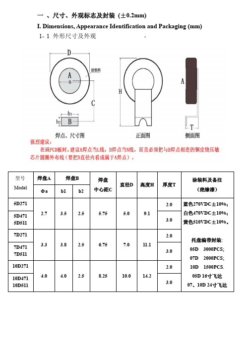
压敏电阻10D封装参数型号规格书大全
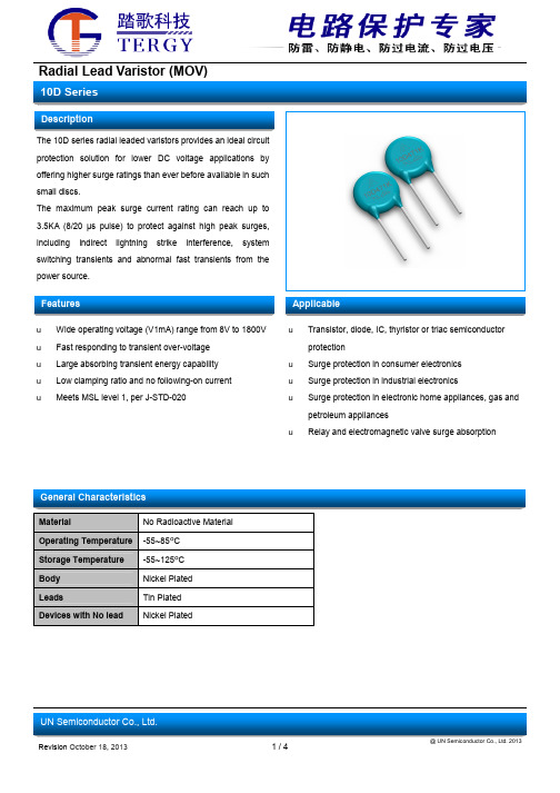
General Characteristics
Material
No Radioactive Material
Operating Temperature -55~85ºC
18(15~21.6) 22(19.5~26) 27(24~30) 33(29.5~36.5) 39(35~43) 47(42~54) 56(50~62) 68(61~75) 82(74~90) 100(90~110) 120(108~132) 150(135~165) 180(162~198) 200(180~220) 220(198~242) 240(216~264) 270(243~297) 300(270~330) 330(297~363) 360(324~396) 390(351~429) 430(387~473 470(423~517) 510(459~561) 560(504~616) 620(558~682) 680(612~748) 750(675~825) 780(702~858) 820(738~902) 910(819~1001) 1000(900~1100) 1100(990~1210) 1800(1620~1980)
3.0 5.0 6.0 7.0 9.0 11.0 13.0 15.0 17.0 18.0 21.0 25.0 30.0 35.0 39.0 42.0 49.0 54.0 58.0 65.0 70.0 80.0 85.0 90.0 92.0 95.0 98.0 100.0 105.0 110.0 130.0 140.0 155.0 250.0
1206(X7R)贴片陶瓷电容器规格书说明书

T
0.80±0.20 1.00±0.20 1.25±0.20 1.60±0.30
WB 0.60±0.30
第 2 页 共 13 页
五. 规格及测试方法:
No
项目
规格
1 使用温度范围 -55~+125℃
外观无可见损伤
2
外观及尺寸
尺寸符合规格要求
3
静电容量 符合规定许容差以内
4
损耗角正切 DF≤2.5%
6
耐电压
无介质被击穿或损伤
Ur=450/500/630V,1.5倍额定电压,5秒
(DC)
1KV≤Ur≤2KV,........ 1.2倍额定电压,5秒
2KV<Ur,............... 1.1 倍额定电压,5 秒 升压时间为:1~3S 保压时间为:5S
7
可焊性
■上锡率应大于 75% ■外观无可见损伤
IR≥1000MΩ或 IR*Cr≥25S IR 取较小值
外观 无可见损伤
静电容 量变化 特性:
率 ┃ΔC/C┃≤20%
高温负
13 荷实验
DF 值 ≤2 倍的初始标准
特性:
IR IR≥2000MΩ或 IR*Cr≥50S 取较小值
充放电流限制在 50mA 以下. 温 度 时 间
100V≤V≤250V 电压 250V<V<1KV
测定.
测试电压:额定电压
测试时间:60±5 秒测
5
绝缘电阻
IR≥4*109Ω,C≤25nF
试湿度:≤75% 测试
IR*Cr≥100*1012Ω,C>25nF 温度:25±5℃
测试充放电电流:≤50mA
Ur=100V,............. 2.5 倍额定电压,5 秒
贴片压敏电阻1206封装参数型号规格书大全
T2
20 uS 1000 uS
Characteristic
Test method and description
The specimen shall be subjected to 125℃ for 1000 hours in a thermostatic bath without High Temperature Storage load and then stored at room temperature and humidity for 1 to 2 hours. The change of
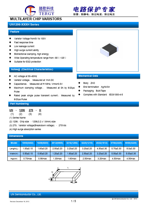
MULTILAYER CHIP VARISTORS
UN1206-XXXH Series
Feature
Varistor Voltage from5V to 100V Fast response time Low leakage current High surge current ability Bidirectional clamping, high energy Wide Operating temperature range from -55℃-125℃ Suitable for ESD protection
Dimensions
Model 1005(0402) 1608(0603) 2012(0805) 3216(1206) 3225(1210) 4532(1812) 5750(2220) 8050(3220)
Length(L) Width(W) High(H)
1.00±0.15 0.50±0.15 0.70max
Notes@(Electrical Characteristics)
AC voltage at 50~60Hz Varistor voltage: Measured at 1mA DC Capacitance: Measured at f=1MHz, Vrms=0.5V Maximum clamping voltage : Measured at 5A by 8/20µs
KRVV0603G5R0NXT压敏电阻规格书

SMD multilayer transient voltage suppressors, standard series
Series/Type: Date: November 2014
1 . Standard series
3 . Electrical specifications and ordering codes
Type:0402~0805
□ Leadless,size 0402~0805 □ Multilayer ceramic construction
□ Wide operating temperature :﹣55℃ to﹢125℃
VB(V)
Clamping voltage 8/20 μs 1A
Transient energy 10/100μs
Peak current 8/20μs
Capacitance @ 1kHz
Vc(V)
ET(J)
Ip(A)
C(pF)
KRVV0402G35R0NXT
2.5 3.3
5 ±10%
10
0.02
10
1.00
200
1500
KRVV1210G270NXT
17
22
27 ±10%
58
1.00
200
1500
KRVV1210G330NXT
20
25
33 ±10%
65
1.00
200
1400
KRVV1210G390NXT
25
30
39 ±10%
72
1.00
200
1206贴片电容最大容值和耐压
1206贴片电容是一种常见的电子元件,用于电路中的滤波、耦合、终端匹配等功能。
在电子设备中,为了保证电路的稳定性和可靠性,选择合适的电容器至关重要。
在选择1206贴片电容时,最大容值和耐压是两个重要的参考指标。
本文将就1206贴片电容的最大容值和耐压进行详细介绍和分析。
一、1206贴片电容的最大容值1206贴片电容的最大容值是指该型号电容器所能容纳的最大电荷量。
在实际应用中,通常会根据具体的电路需求来选择合适的最大容值。
以下是影响1206贴片电容最大容值的主要因素:1. 电路需求:不同的电路对电容容值的要求有所不同。
一般来说,需要大电流通过的电路需要容值较大的电容器。
2. 工作频率:1206贴片电容的最大容值还受到工作频率的影响。
在高频电路中,需要选择容值较小的电容器来确保性能稳定。
3. 电压水平:1206贴片电容的最大容值也与电压水平相关。
在高压电路中,需要选择承受高电压的大容值电容器。
根据以上因素,选择1206贴片电容的最大容值时,需要综合考虑电路需求、工作频率和电压水平,以确保电容器能够有效地满足电路的需求。
二、1206贴片电容的耐压1206贴片电容的耐压是指电容器能够承受的最大电压。
在电子设备中,耐压是一个非常重要的指标,直接关系到电路的安全可靠运行。
以下是影响1206贴片电容耐压的主要因素:1. 化学材料:1206贴片电容的材料不同,在耐压方面的性能也有所差异。
一般来说,有机电解质电容器的耐压较低,而钽质电解质电容器的耐压较高。
2. 结构设计:电容器的内部结构设计也会影响其耐压能力。
合理的结构设计能够有效提高电容器的耐压性能。
3. 工艺水平:生产工艺水平直接影响了电容器的品质,对于耐压来说尤为重要。
优质的工艺能够确保电容器的耐压性能稳定可靠。
在选择1206贴片电容时,需要根据具体电路需求和工作环境来确定合适的耐压水平,以确保电容器能够安全稳定地工作。
总结:1206贴片电容的最大容值和耐压是选择该型号电容器时需要重点考虑的指标,合理选择最大容值和耐压能够有效地满足电路需求,确保电子设备的稳定性和可靠性。
1206全彩贴片LED-1206全彩共阴LED规格书

SPECIFICATION FOR APPROVAL
客户 Customer:
客户品号 Customer P/N:
鑫光硕品号 Xgs Model:
规格 Specification :
XGS-PB3216UEUGUB-04-B SMD 1206 RGB共阴 20MA
制作 Prepared By:
审核 Checked By:
IF
25
Reverse Voltage
VR
5
Operating Temperature Range
Topr
-40℃~85℃
Storage Temperature Range
Tstg
-40℃~100℃
IFP condition: pulse width ≤1ms ,duty cycle ≤1/10
20
0/1
60cm/min,2 times
(2)Criteria of judging the damage
Item
Forward voltage Reverse current
Luminous intensity
Wave length
Appearance
Symbol VF IR IV
λD/λP /
◆ Applications:
Automotive and Telecommunication Flat backlight for LCD ,switch and symbol in telephone and fax General use for indicators
◆ Package Dimensions:
◆ Electrical Optical Characteristics(Ta=25℃)
KRVV全系列压敏电阻规格书

SMD multilayer transient voltage suppressors, standard series
Series/Type: Date: November 2014
1 . Standard series
during manufacturing according to the request, please contact our sales department if needed
Type:1206~1812
□ Leadless,size 3216~4532
□ Multilayer ceramic construction
180
780
KRVV1210G8R0NXT
4 5.6
8 ±10%
15.5
0.50
100
1600
KRVV1210G120NXT
6
8
12 ±10%
25
0.50
100
1600
KRVV1210G180NXT
11
14
18 ±10%
35
1.00
200
1500
KRVV1210G240NXT
14
18
24 ±10%
45
20
0.03
10
480
KRVV0603G5R0NXT
2.5 3.3
5 ±10%
10
0.10
20
360
KRVV0603G8R0NXT
4 5.6
8 ±10%
15.5
0.10
20
270
KRVV0603G120N121T
抗浪涌贴片电阻 1206 1Ω ±5% 35W

本文主要介绍抗浪涌贴片电阻1206 1Ω ±5% 3/5W型号详情,相对于普通产品抗浪涌产品不经过镭射修阻,所以其导电面积必然大于不同产品,具有更高的耐压能力。
高精度抗浪涌电阻管控切割长度,使产品具有一定程度的精度且有较好的抗脉冲能力,普通抗浪涌电阻适用于对精度要求较低,且需要很高的抗浪涌能力场合,如充电端口,功放电路等;高精度抗浪涌产品适用于对精度要求较高且需求有一定的抗浪涌能力的场合。
抗浪涌贴片电阻1206 1Ω ±5% 3/5W商品信息
商品编码06SUP048075
原厂编码SWR013216(1206)L1R0JTF
品牌美隆(SUP)
毛重0.03
封装规格1206(3216)
阻值1Ω
精度±5%
功率3/5W
商品型号抗浪涌贴片电阻1206 1Ω ±5% 3/5W
抗浪涌贴片电阻1206 1Ω ±5% 3/5W型号,全部来自原厂,10PCS起订,抗浪涌贴片电阻1206 1Ω ±5% 3/5W型号价格0.1828。
以上就是抗浪涌贴片电阻1206 1Ω ±5% 3/5W型号详情,希望对各位有帮助。
压敏电阻常用型号及参数

压敏电阻常用型号及参数压敏电阻是一种电阻器件,其电阻值会随着外加电压的变化而变化。
由于其具有良好的电压响应特性,常被用于电路中的过压保护、电源滤波和信号调节等方面。
下面将介绍一些常用的压敏电阻型号及其参数。
1.NTC压敏电阻:NTC(Negative Temperature Coefficient)压敏电阻的电阻值会随着温度的升高而降低。
其常用型号有:-10D-9型:电阻值范围为10Ω~1MΩ,额定功率为0.15W~0.5W,最大工作电流为5A,最大工作电压为250V。
-10D-11型:电阻值范围为10Ω~10MΩ,额定功率为0.15W~0.5W,最大工作电流为3A,最大工作电压为600V。
2.PTC压敏电阻:PTC(Positive Temperature Coefficient)压敏电阻的电阻值会随着温度的升高而增加。
其常用型号有:-15D-11型:电阻值范围为1Ω~100KΩ,额定功率为0.4W~0.6W,最大工作电流为10A,最大工作电压为260V。
-15D-22型:电阻值范围为10Ω~100KΩ,额定功率为0.4W~0.6W,最大工作电流为10A,最大工作电压为600V。
3.SMD压敏电阻:SMD(Surface Mount Device)压敏电阻通常采用贴片封装,适用于表面贴装技术。
- 0603型:尺寸为1.6mm×0.8mm×0.8mm,电阻值范围为1Ω~10MΩ,额定功率为0.05W~0.1W,最大工作电流为100mA,最大工作电压为50V。
- 0805型:尺寸为2.0mm×1.25mm×0.8mm,电阻值范围为1Ω~10MΩ,额定功率为0.1W~0.5W,最大工作电流为200mA,最大工作电压为100V。
需要注意的是,以上仅列举了部分常见的压敏电阻型号及参数,实际应用中还有更多的型号和规格可供选择。
在选择压敏电阻时,应根据具体的应用需求综合考虑电阻值范围、额定功率、工作电流和工作电压等参数,以确保电路性能的稳定和可靠。
1206 电阻通用规格书
o d u c t s p e c i f i c a t i o n – F e b r u a r y 6, 2013 V .5S u p e r s e d e s D a t e o f M a r . 06, 2003Y A G E O B R A N D o r d e r i n g c o d eGLOBAL PART NUMBER (PREFERRED )RC1206 X R - XX XXXX L(1) (2) (3) (4) (5) (6)(1) TOLERANCED = ±0.5% F = ±1%J = ±5% (for Jumper ordering, use code of J)(2) PACKAGING TYPER = Paper taping reel(3) TEMPERATURE COEFFICIENT OF RESISTANCE– = Base on spec(4) TAPING REEL07 = 7 inch dia. Reel 10 = 10 inch dia. Reel 13 = 13 inch dia. Reel(5) RESISTANCE VALUEThere are 2~4 digits indicated the resistor value. Letter R/K/M is decimal point, no need to mention the last zero after R/K/M, e.g.1K2, not 1K20.Detailed resistance rules show in table of “Resistance rule of global part number”.(6) DEFAULT CODELetter L is system default code for order only (Note)ORDERING INFORMATION - GLOBAL PART NUMBER & 12NC Both part numbers are identified by the series, size, tolerance, packing type, temperature coefficient, taping reel and resistance value.SCOPEThis specification describes RC1206 series chip resistors with lead-free terminations made by thick film process.APPLICATIONS● All general purpose applicationFEATURES● Halogen Free Epoxy●RoHS compliant- Products with lead freeterminations meet RoHS requirements- Pb-glass contained in electrodes,resistor element and glass are exempted by RoHS●Reducing environmentally hazardous wastes●High component and equipment reliability● Saving of PCB space●None forbidden-materials used in products/productionO RDERING EXAMPLEThe ordering code of a RC1206 chip resistor, value 56 X with ±1% tolerance, supplied in 7-inch tape reel is: RC1206FR-0756RL.NOTE1. All our RSMD products meet RoHS compliant and Halogen Free. "LFP" of the internal 2D reel label mentions "Lead Free Process"2. On customized label, "LFP" or specific symbol can be printedResistance rule of global part numberResistance code rule Example0R0R = Jumper XRXX(1 to 9.76 Ω) 1R = 1 Ω1R5 = 1.5 Ω9R76 = 9.76 ΩXXRX(10 to 97.6 Ω) 10R = 10 Ω97R6 = 97.6 ΩXXXR(100 to 976 Ω) 100R = 100 ΩXKXX(1 to 9.76 K Ω) 1K = 1,000 Ω9K76 = 9760 ΩXMXX(1 to 9.76 M Ω) 1M = 1,000,000 Ω9M76= 9,760,000 Ω12NC CODE2322 / 2350 XXX XXXXX L(1) (2) (3) (4)TYPE/ 1206 START IN (1) TOL. (%) RESISTANCERANGE PAPER / PE TAPE ON REEL (units) (2) 5,000 10,000/not preferred 20,000RC01 2322 ±5% 1 to 10 M Ω711 61xxx711 51xxx711 81xxx RC02 2322 ±1% 1 to 10 M Ω 724 6xxxx 724 7xxxx 724 8xxxxHRC01 2350±5% 11 to 22 M Ω 520 10xxx-- Jumper 2322 - 0 Ω 711 91032 711 91005711 92004P H Y C O M P B R A N D o r d e r i n g c o d e sBoth GLOBAL PART NUMBER (preferred) and 12NC (traditional) codes are acceptable to order Phycomp brand products. GLOBAL PART NUMBER (PREFERRED ) For detailed information of GLOBAL PART NUMBER and ordering example, please refer to page 2.Resistance decade (3) Last digit 0.01 to 0.0976 X 00.1 to 0.976 X 71 to 9.76 X 810 to 97.6 X 9100 to 976 X 11 to 9.76 K X 210 to 97.6 K X 3100 to 976 K X 41 to 9.76 M X 510 to 97.6 M X6Example: 0.02X = 0200 or 200 0.3 X = 3007 or 3071 X=1008 or 10833 K X = 3303 or 333 10 M X = 1006 or 106Last digit of 12NC(1) The resistors have a 12-digit ordering code starting with 2322 / 2350.(2) The subsequent 4 or 5 digits indicate the resistor tolerance andpackaging. (3) The remaining 4 or 3 digits represent the resistance value with thelast digit indicating the multiplier as shown in the table of “Last digit of 12NC”. (4) Letter L is system default code for order only (Note) O RDERING EXAMPLEThe ordering code of a RC02 resistor, value 56 X with ±1% tolerance, supplied in tape of 10,000 units per reel is: 232272465609L or RC1206FR-0756RL.NOTE1. All our RSMD products meet RoHS compliant and Halogen Free. "LFP" of the internal 2D reel label mentions "Lead Free Process"2. On customized label, "LFP" or specific symbol can be printedCONSTRUCTIONThe resistor is constructed on top of a high-grade ceramic body.Internal metal electrodes are added on each end to make the contacts to the thick film resistive element. The composition of the resistive element is a noble metal imbedded into a glass and covered by a second glass to prevent environment influences. The resistor is laser trimmed to the rated resistance value. The resistor is covered with a protective epoxy coat, finally the two external terminations (matte tin on Ni-barrier) are added. See fig.3DIMENSIONSTYPE RC1206L (mm)3.10 ± 0.10W (mm) 1.60 ± 0.10H (mm) 0.55 ± 0.10I 1 (mm) 0.45 ± 0.20I 2 (mm)0.40 ± 0.20T able 1O U T L I N E SMARKINGRC1206No markingFor further marking information, please refer to data sheet “Chip resistors marking”ELECTRICAL CHARACTERISTICS CHARACTERISTICS RC1206 1/4 WOperating Temperature Range –55 °C to +155 °CMaximum Working Voltage 200 V Maximum Overload Voltage 400 V Dielectric Withstanding Voltage500 VResistance Range5% (E24) 1 Ω to 22 M Ω1% (E24/E96) 1 Ω to 10 M Ω0.5% (E24/E96) 10 to 1 M ΩΩZero Ohm Jumper < 0.05 ΩTemperature Coefficient1 Ω ≤ R ≤ 10 Ω±200 ppm/°C ±200 ppm/°C 10 M Ω < R ≤ 22 M Ω10 Ω < R ≤ 10 M Ω±100 ppm/°CJumper CriteriaRated Current 2 A Maximum Current10 AFOOTPRINT AND SOLDERING PROFILESFor recommended footprint andsoldering profiles, please refer to data sheet “Chip resistors mounting”.T able 2PACKING STYLE AND PACKAGING QUANTITY PRODUCT TYPE PACKING STYLEREEL DIMENSIONQUANTITY PER REELRC1206 Paper Taping Reel (R) 7" (178 mm) 5,000 units10" (254 mm) 10,000 units13" (330 mm)20,000 unitsNOTE1. For paper tape and reel specification/dimensions, please see the special data sheet “Chip resistors packing”T able 3Packing style and packaging quantityFUNCTIONAL DESCRIPTIONP O W E R R A T I N GRC1206 rated power at 70°C is 1/4 W R ATED VOLTAGEThe DC or AC (rms) continuous working voltage corresponding to the rated power is determined by the following formula:V=R)(P Xor max. working voltage whichever is less WhereV=Continuous rated DC or AC (rms) working voltage (V) P=Rated power (W) R=Resistance value (X )TESTS AND REQUIREMENTSTEST TESTMETHOD PROCEDURE REQUIREMENTSTemperature Coefficient of Resistance (T.C.R.) IEC 60115-1 4.8 At +25/–55 °C and +25/+125 °C Refer to table 2Formula:T.C.R= ------------------------- ×106 (ppm/°C)Wheret1=+25 °C or specified room temperaturet2=–55 °C or +125 °C test temperatureR1=resistance at reference temperature in ohmsR2=resistance at test temperature in ohmsLife/Endurance IEC 60115-1 4.25.1 At 70±5 °C for 1,000 hours, RCWV applied for1.5 hours on, 0.5 hour off, still air required ±(1.0%+0.05 ) for 1%,Ω0.5% tol.±(3.0%+0.05 Ω) for 5% tol. <100 mΩ for JumperHigh Temperature Exposure/ Endurance at Upper Category Temperature IEC 60068-2-2 1,000 hours at 155±5 °C, unpowered ±(1.0%+0.05 ) for 1%,Ω0.5% tol.±(2.0%+0.05 Ω) for 5% tol.<50 mΩ for JumperMoisture Resistance MIL-STD-202G Method-106G Each temperature / humidity cycle is defined at 8hours, 3 cycles / 24 hours for 10d. with 25 °C /65 °C 95% R.H, without steps 7a & 7b,unpoweredParts mounted on test-boards, withoutcondensation on partsMeasurement at 24±2 hours after test conclusion±(0.5%+0.05 ) for 1%,Ω0.5% tol.±(2.0%+0.05 Ω) for 5% tol.<100 mΩ for JumperThermal Shock MIL-STD-202G Method-107G -55/+125 °CNumber of cycles required is 300. DevicesunmountedMaximum transfer time is 20 seconds. Dwell timeis 15 minutes. Air – Air ±(0.5%+0.05 ) for 1%,Ω0.5% tol.±(1%+0.05 Ω) for 5% tol.<50 mΩ for JumperShort Time Overload IEC60115-1 4.13 2.5 times of rated voltage or maximum overloadvoltage whichever is less for 5 sec at roomtemperature±(1.0%+0.05 ) for 1%,Ω0.5% tol.±(2.0%+0.05 Ω) for 5% tol.<50 mΩ for JumperNo visible damageT able 4 Test condition, procedure and requirementsR2–R1R1(t2–t1)TEST TESTMETHOD PROCEDURE REQUIREMENTSBoard Flex/ Bending IEC 60068-2-21 Chips mounted on a 90mm glass epoxy resinPCB (FR4)2 mm bendingBending time: 60±5 seconds±(1.0%+0.05 Ω)<50 mΩ for JumperNo visible damageLow Temperature Operation IEC 60068-2-1 The resistor shall be subjected to a DC ratedvoltage for 1.5 h-on, 0.5 h-off, at -55±3 °CThis constitutes shall be repeated for 96 hoursHowever the applied voltage shall not exceedthe maximum operating voltage±(0.5%+0.05 )Ωfor 1%,0.5% tol.±(1.0%+0.05 Ω) for 5% tol.No visible damageInsulation Resistance IEC 60115-1 4.6 Rated continuous overload voltage (RCOV)for 1 minuteType RC1206Voltage (DC) 100 V≥10 GΩDielectric Withstand Voltage IEC 60115-1 4.7 Maximum voltage (V rms) applied for 1 minuteType RC1206Voltage (AC) 500 V rmsNo breakdown or flashoverResistance to Solvent IPC/JEDEC J-STD-020D lsopropylalcohol (C3H7OH) followed bybrushingNo smearedNoise IEC 60115-1 4.12 Maximum voltage (Vrms) applied Resistors range ValueR < 100 Ω10 dB100 Ω≤ R < 1 KΩ20 dB1 KΩ≤ R < 10 KΩ30 dB10 KΩ≤ R < 100 KΩ40 dB100 KΩ≤ R < 1 MΩ46 dB1 MΩ≤ R ≤ 22 MΩ48 dBHumidity IEC 60115-1 4.37 Steady state for 1000 hours at 40 °C / 95% R.H.RCWV applied for 1.5 hours on and0.5 hour off ±(1.0%+0.05 ) for 1%,Ω0.5% tol.±(2.0%+0.05 Ω) for 5% tol. <100 mΩ for JumperTEST TESTMETHODPROCEDURE REQUIREMENTSIntermittent Overload IEC 60115-1 4.39 2.5 times of rated voltage or maximumoverload voltage whichever is less for 1 secondon and 25 seconds off; total 10,000 cycles±(1.0%+0.05 ) for 1%,Ω0.5% tol.±(2.0%+0.05 Ω) for 5% tol.<100 mΩ for JumperSolderability- Wetting IPC/JEDEC J-STD-002B test B Electrical Test not requiredMagnification 50XSMD conditions:1st step: method B, aging 4 hours at 155 °Cdry heat2nd step: leadfree solder bath at 245±3 °CDipping time: 3±0.5 seconds Well tinned (≥95% covered) No visible damage- Leaching IPC/JEDEC J-STD-002B test D Leadfree solder, 260 °C, 30 secondsimmersion timeNo visible damage- Resistance to Soldering Heat IEC 60068-2-58 Condition B, no pre-heat of samplesLeadfree solder, 260 °C, 10 secondsimmersion timeProcedure 2 for SMD: devices fluxed andcleaned with isopropanol±(0.5%+0.05 ) for 1%,Ω0.5% tol.±(1.0%+0.05 Ω) for 5% tol.<50 mΩ for JumperNo visible damageREVISION HISTORYREVISION DATE CHANGE NOTIFICATION DESCRIPTIONVersion 5 Feb 06, 2013 - -Marking updated-Add 0.5% toleranceVersion 4 Jul 02, 2009 - - Test Items and methods updated- Test requirements upgradedVersion 3 Jul 15, 2008 - - Change to dual brand datasheet that describe RC1206 with RoHS compliant- Description of "Halogen Free Epoxy" added- Define global part numberVersion 2 Sep 03, 2004 - - New datasheet for 1206 thick film 1% and 5% with lead-free terminations- Replace the 1206 part of pdf files: RC01_11_21_31_5, RC02_12_22_32_10,and HRC01_5_4- Test method and procedure updated- PE tape added (paper tape will be replaced by PE tape)- High ohmic products combined into standard products.“ Yageo reserves all the rights for revising the content of this datasheet without further notification, as long as the products itself are unchanged. Any product change will be announced by PCN.”國巨股份有限公司 新北市新店區寶橋路233之1號3樓 3F., 233-1, Baoqiao Rd., Xindian, Taipei 231, Taiwan t. +886.2.2917.7555 f. +886.2.2917.5078To remove AC0603/0805/1206 and RC0603/0805/1206 markingJanuary 16th , 2013Dear Customers,Yageo would like to announce that we will remove the Resistance Marking on Yageo’s R Chip case sizes 0603/0805/1206 products from March 1st 2013 for the purposes of reducing unnecessary chemical usages for environmental protections. To identify the product resistance value, the label on the reels has been serving and will continue serving the purposes. As for the product performance, features, specifications, manufacturing process and locations remain the same. That is to say the elimination of the resiatance marking on the product appearance has no impact on the product functionality and you can feel free to use it for your current applications.Yageo has provided no resistance marking on R Chip 0402/0201/01005 and on the entire MLCC family ever since. Given Yageo has been devoted to being eco-friendly, we decide to eliminate the marking on the R Chip of the sizes of 0603 and the above as soon as possible. There will be a short period of time that both types of the products, with marking and without marking, co exist while we are changing the production lines one by one. We highly appreciate your understanding that we may ship the products in parallel for some time. Yageo commits that we will make full efforts to shorten the overlapping period as much as we can.We truly appreciate being your business partner and serving your passivecomponent needs. If there are any questions, please feel free to contact Yageo’s sales offices.Sincerely Yours,Product Business Unit, R chip product marketing Yageo CorporationNotice Notice通知信取消AC及RC 0603/0805/1206系列字码印制2013年1月15日亲爱的客户,您好为了维护环境并减少非必要的化学原料使用,国巨在此通知您:自2013年3月1日起,将生产0603/0805/1206无字码印制的电阻。
贴片压敏电阻TG1206型号参数规格书
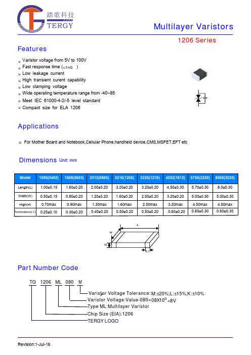
FeaturesApplicationsRevision:18-Jul-161206 SeriesVaristor voltage from 5V to 100V Fast response time ( )Low leakage current High transient curent capability Low clamping voltageWide operating temperature range from -40~85Meet IEC 61000-4-2/-5 level standarduuu uu u u uFor Mother Board and Notebook,Cellular Phone,handheld device,CMO S ,MO S FET,EFT etcDimensionsUnit: mm<1nS℃Compact size for ELA 1206uPart Number CodeTG 1206TERGY LOGO___________ML 080MChip Size (EIA):1206Type ML:Multilayer VaristorVaristor Voltage:Value-080=08X100=8V Varistor Voltage Tolerance:M:±20%;L:±15%;K:±10%Electriacl CharacteristicsRevision:18-Jul-16Surge Current Standard Waveform 1206 SeriesIEC61000-4-5 StandardsT1T2SEVERITY LEVELT1 T2 1 8 uS 20 uS 210 uS1000 uS8/20µs waveform currentOperating Temperature -40 ~ +85ºC Storage Temperature -40 ~ +125ºC Response Time <1 nsSolderability245±5ºC, 3±1sec Solder leach resistance 260±5ºC, 10±1sec Storage Temperature 5 ~ 40ºC Relative Humidity To 65% Taping Package Storage ConditionStorage Time12 Months maxGeneral Technical Data1206 SeriesRevision:18-Jul-16Environmental Reliability TestingCharacteristicTest method and descriptionHigh Temperature Storage The specimen shall be subjected to 125℃ for 1000 hours in a thermostatic bath withoutload and then stored at room temperature and humidity for 1 to 2 hours. The change ofvaristor voltage shall be within 10%.Step Temperature Period 1 -40±3℃30min ±3 2 Room Temperature 1~2hours3 125±2℃30min ±3Temperature CycleThe temperature cycle of specified temperature shall be repeated five times and then stored atroom temperature and humidity for one two hours. The change of varistor voltage shall be within 10%and mechanical damage shall be examined.4Room Temperature 1~2hoursHigh Temperature LoadAfter being continuously applied the maximum allowable voltage at 85℃ for 1000hours, the specimen shall be stored at room temperature and humidity for one or hours, the change of varistor voltage shall be within 10%.Damp Heat Load/Humidity LoadThe specimen should be subjected to 40℃,90 to 95%RH environment, and the maximum allowable voltage applied for 1000 hours, then stored at room temperature and humidity for one or two hours. The change of varistor voltage shall be within 10%.Low Temperature Storage The specimen should be subjected to -40℃, without load for 1000 hours and thenstored at room temperature for one two hours. The change of varistor voltage shall bewithin 10%.Recommended Soldering ConditionsNote that this product will be easily damaged by rapid heating, rapid cooling or local heating.Do not give heat shock over 100°C in the process of soldering. We recommend to take preheating and gradual coolingSoldering gun procedureNote the follows, in case of using solder gun for replacement. 1) The tip temperature must be less than 280 for the period within 3 seconds by using soldering gun under 30W2) The soldering gun tip shall not touch this product directly.Soldering volumeNote that excess of soldering volume will easily get crack the body of this product.Revision:18-Jul-161206 Series◆Carrier tape transparent cover tape should be heat-sealed to carry the products,and the reel should be used to reel the carrier tape.◆The adhesion of the heat-sealed cover tape shall be 40﹢20/﹣15grams.◆Both the head and the end portion of taping shall be empty for reel package and SMT auto-pickup machine.And a normal paper tape shall be connected in the head of taping for the operator handle.type A 0±0.10B 0±0.10K 0±0.10T ±0.05T 2±0.05D 0+0.10D 1±0.05P 1±0.10P 2±0.05P 0±0.05W ±0.20 E ±0.10 F ±0.050402 1.08 1.88 1.04 0.22 0.87 1.50 1.00 4.00 2.00 4.00 8.00 1.75 3.50 0603 1.08 1.88 1.04 0.22 1.17 1.50 1.00 4.00 2.00 4.00 8.00 1.75 3.50 0805 1.42 2.30 1.04 0.22 1.26 1.50 1.00 4.00 2.00 4.00 8.00 1.75 3.50 1206 1.88 3.50 1.27 0.20 1.49 1.50 1.00 4.00 2.00 4.00 8.00 1.75 3.50 1210 2.18 3.46 1.45 0.22 1.77 1.50 1.00 4.00 2.00 4.00 8.00 1.75 3.50 1812 3.66 4.95 1.74 0.25 1.99 1.50 1.50 8.00 2.00 4.00 12.00 1.75 5.50 2220 5.10 5.97 2.80 0.25 3.05 1.50 1.50 8.00 2.00 4.00 12.00 1.75 5.50 32205.50 8.50 2.80 0.30 3.50 1.50 1.50 8.00 2.00 4.00 16.00 1.757.50Packaging Dementions Unit:MillimetersReel DimensionsUnit:MillimetersType A B C D E W W 10402~1210178±160±0.513±0.221±0.22±0.59±0.5 1.5±0.151812~3220178±160±0.513.5±0.221±0.22±0.513.6±0.51.5±0.15Type 04020603080512061210181222203220Quantity100004000400030003000100010001000Packing Quantity。
GRACEKRVVVaristor压敏电阻规格书

4 5.6
12 ±10%
KRVV0403G120N201T
4 5.6
12 ±10%
KRVV0402G120N361T
4 5.6
12 ±10%
KRVV0403G120N481T
4 5.6
12 ±10%
KRVV0603G5R0NXT
2.5 3.3
5 ±10%
KRVV0603G8R0NXT
4 5.6
8 ±10%
Peak current 8/20μs
Capacitance @ 1kHz
Vc(V)
ET(J)
Ip(A)
C(pF)
KRVV1206G8R0NXT
4 5.6
8 ±10%
15.5
0.02
100
1500
KRVV1206G120NXT
6
8
12 ±10%
25
0.02
100
1300
KRVV1206G180NXT
35
45
56 ±10%
Notes:
1.Typical leakage at 25℃<50uA, maximum leakage 100uA。
Clamping Transient Peak Capacitance
voltage energy current
8/20 μs 1A 10/100μs 8/20μs
2 . Size
Model 0402(1005) 0603(1608) 0805(2012) 1206(3216) 1210(3225) 1812(4532) 2220(5650) 3220(08CL) 4032(10CL) 4840(12CL)
Length(L) 1.00±0.20 1.60±0.20 2.00±0.20 3.20±0.20 3.20±0.20 4.50±0.20 5.60±0.20 8.00±0.30 10.0±0.30 12.0±0.30
