SMD802 spec v10 chs中文规格书
莫克8口无管理以太网开关产品说明书
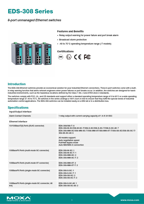
EDS-308Series8-port unmanaged Ethernet switchesFeatures and Benefits•Relay output warning for power failure and port break alarm •Broadcast storm protection•-40to 75°C operating temperature range (-T models)CertificationsIntroductionThe EDS-308Ethernet switches provide an economical solution for your industrial Ethernet connections.These 8-port switches come with a built-in relay warning function that alerts network engineers when power failures or port breaks occur.In addition,the switches are designed for harsh industrial environments,such as the hazardous locations defined by the Class 1Div.2and ATEX Zone 2standards.The switches comply with FCC,UL,and CE standards and support either a standard operating temperature range of 0to 60°C or a wide operating temperature range of -40to 75°C.All switches in the series undergo a 100%burn-in test to ensure that they fulfill the special needs of industrial automation control applications.The EDS-308switches can be installed easily on a DIN rail or in a distribution box.SpecificationsInput/Output InterfaceAlarm Contact Channels1relay output with current carrying capacity of 1A @24VDCEthernet Interface10/100BaseT(X)Ports (RJ45connector)EDS-308/308-T:8EDS-308-M-SC/308-M-SC-T/308-S-SC/308-S-SC-T/308-S-SC-80:7EDS-308-MM-SC/308-MM-SC-T/308-MM-ST/308-MM-ST-T/308-SS-SC/308-SS-SC-T/308-SS-SC-80:6All models support:Auto negotiation speed Full/Half duplex modeAuto MDI/MDI-X connection100BaseFX Ports (multi-mode SC connector)EDS-308-M-SC:1EDS-308-M-SC-T:1EDS-308-MM-SC:2EDS-308-MM-SC-T:2100BaseFX Ports (multi-mode ST connector)EDS-308-MM-ST:2EDS-308-MM-ST-T:2100BaseFX Ports (single-mode SC connector)EDS-308-S-SC:1EDS-308-S-SC-T:1EDS-308-SS-SC:2EDS-308-SS-SC-T:2100BaseFX Ports (single-mode SC connector,80km)EDS-308-S-SC-80:1EDS-308-SS-SC-80:2Standards IEEE802.3for10BaseTIEEE802.3u for100BaseT(X)and100BaseFXIEEE802.3x for flow controlOptical Fiber800Typical Distance4km5km40km80kmWavelen-gthTypical(nm)130013101550TX Range(nm)1260to13601280to13401530to1570 RX Range(nm)1100to16001100to16001100to1600Optical PowerTX Range(dBm)-10to-200to-50to-5 RX Range(dBm)-3to-32-3to-34-3to-34 Link Budget(dB)122929 Dispersion Penalty(dB)311Note:When connecting a single-mode fiber transceiver,we recommend using anattenuator to prevent damage caused by excessive optical power.Note:Compute the“typical distance”of a specific fiber transceiver as follows:Linkbudget(dB)>dispersion penalty(dB)+total link loss(dB).DIP Switch ConfigurationEthernet Interface Port break alarmSwitch PropertiesMAC Table Size2kbitsPacket Buffer Size768KProcessing Type Store and ForwardPower ParametersInput Current EDS-308/308-T:0.07A@24VDCEDS-308-M-SC/S-SC Series,308-S-SC-80:0.12A@24VDCEDS-308-MM-SC/MM-ST/SS-SC Series,308-SS-SC-80:0.15A@24VDC Connection1removable6-contact terminal block(s)Operating Voltage9.6to60VDCInput Voltage Redundant dual inputs,12/24/48VDCReverse Polarity Protection SupportedOverload Current Protection SupportedPhysical CharacteristicsHousing MetalIP Rating IP30Dimensions53.6x135x105mm(2.11x5.31x4.13in)Weight790g(1.75lb)Installation DIN-rail mounting,Wall mounting(with optional kit) Environmental LimitsOperating Temperature Standard Models:-10to60°C(14to140°F)Wide Temp.Models:-40to75°C(-40to167°F) Storage Temperature(package included)-40to85°C(-40to185°F)Ambient Relative Humidity5to95%(non-condensing)Standards and CertificationsHazardous Locations ATEX,Class I Division2EMI CISPR32,FCC Part15B Class AMaritime DNV-GLEMC EN55032/24Vibration IEC60068-2-6EMS IEC61000-4-2ESD:Contact:6kV;Air:8kVIEC61000-4-3RS:80MHz to1MHz:20V/mIEC61000-4-4EFT:Power:2kV;Signal:1kVIEC61000-4-5Surge:Power:2kV;Signal:2kVIEC61000-4-6CS:10VIEC61000-4-8PFMFSafety UL508,UL60950-1,CSA C22.2No.60950-1 Shock IEC60068-2-27Freefall IEC60068-2-32MTBFTime255,528hrsStandards MIL-HDBK-217FWarrantyWarranty Period5yearsDetails See /warrantyPackage ContentsDevice1x EDS-308Series switchInstallation Kit1x cap,plastic,for SC fiber port2x cap,plastic,for SC fiber port(-SC models)2x cap,plastic,for ST fiber port(-ST models) Documentation1x quick installation guide1x warranty cardDimensionsOrdering InformationModel Name 10/100BaseT(X)PortsRJ45Connector100BaseFX PortsMulti-Mode,SCConnector100BaseFX PortsMulti-Mode,STConnector100BaseFX PortsSingle-Mode,SCConnectorOperating Temp.EDS-3088–––0to60°CEDS-308-T8–––-40to75°C EDS-308-M-SC71––0to60°CEDS-308-M-SC-T71––-40to75°C EDS-308-MM-SC62––0to60°CEDS-308-MM-SC-T62––-40to75°C EDS-308-MM-ST6–2–0to60°CEDS-308-MM-ST-T6–2–-40to75°C EDS-308-S-SC7––10to60°CEDS-308-S-SC-T7––1-40to75°C EDS-308-SS-SC6––20to60°CEDS-308-SS-SC-T6––2-40to75°C EDS-308-S-SC-807––10to60°CEDS-308-SS-SC-806––20to60°C Accessories(sold separately)Power SuppliesDR-120-24120W/2.5A DIN-rail24VDC power supply with universal88to132VAC or176to264VAC input byswitch,or248to370VDC input,-10to60°C operating temperatureDR-452445W/2A DIN-rail24VDC power supply with universal85to264VAC or120to370VDC input,-10to50°C operating temperatureDR-75-2475W/3.2A DIN-rail24VDC power supply with universal85to264VAC or120to370VDC input,-10to60°C operating temperatureMDR-40-24DIN-rail24VDC power supply with40W/1.7A,85to264VAC,or120to370VDC input,-20to70°Coperating temperatureMDR-60-24DIN-rail24VDC power supply with60W/2.5A,85to264VAC,or120to370VDC input,-20to70°Coperating temperatureWall-Mounting KitsWK-46Wall-mounting kit,2plates,8screws,46.5x66.8x1mmRack-Mounting KitsRK-4U19-inch rack-mounting kit©Moxa Inc.All rights reserved.Updated Jan30,2019.This document and any portion thereof may not be reproduced or used in any manner whatsoever without the express written permission of Moxa Inc.Product specifications subject to change without notice.Visit our website for the most up-to-date product information.。
广州致远电子ZM602系列Wi-Fi模块数据手册说明书
©2022 Guangzhou ZHIYUAN Electronics Co., Ltd.ZM602系列Wi-Fi 模块数据手册Wi-Fi 模块DS01010101 1.2 Date:2022/9/16—————————————— 概述 ZM602系列Wi-Fi 模块是广州致远电子有限公司基于博流BL602系列芯片开发的高性能Wi-Fi+BLE 模块产品。
产品支持IEEE802.11 b/g/n 三种Wi-Fi 通信协议,支持无线热点、无线客户端、无线热点+无线客户端三种工作模式,采用20MHz 标准带宽,可以提供最大72.2Mbit/s 物理层速率。
此外,产品同时具备蓝牙通信功能,支持蓝牙5.0通信协议。
ZM602系列Wi-Fi 模块将完整的射频收发电路集成在一个模块上,同时支持Wi-Fi 和BLE 两种通信模式。
模块的射频输出支持IPEX 座连接外部天线或者直接使用模块自带的PCB 天线模块,使用十分灵活,用户可以根据自己的需求进行选择。
模块与主控设备通过UART 或者SDIO 接口进行通信,简单方便,可以帮助用户产品更快的投入市场,增加用户产品的竞争力。
———————————— 产品应用 ◆ 工业数据采集 ◆ 物联网智能终端 ◆ 智能家居 ◆ 智能遥控器————————————— 产品图片———————————— 产品特性 ◆ 频率范围:2400~2483.5MHz ◆ 无线协议:IEEE 802.11 b/g/nBLE 5.0◆ 工作电压:3.0~3.6 V◆ 发射功率:************************** ************* 4dBm@BLE◆ 接收灵敏度:***************************************-97dBm@BLE◆ 射频输出:PCB 天线、IPEX 连接器 ◆ 通信接口:UART 或SDIO ◆ 温度范围:-30~+85℃———————————— 订购信息 注:见选型表©2022 Guangzhou ZHIYUAN Electronics Co., Ltd.修订历史文档版本 日期 原因V1.002022.04.25首次发布 V1.012022.08.17增加产品实物图; 更新产品选型表;优化产品尺寸图; 优化引脚定义说明; 更新BLE 发射功率; 新增包装信息;目录1. 产品简介 (1)1.1概述 (1)1.2产品特性 (1)1.3典型应用 (2)1.4产品选型表 (2)2. 外观尺寸 (3)3. 引脚定义 (4)3.1UART接口 (4)3.3SDIO接口 (7)4. 性能参数 (9)4.1串口波特率 (9)4.2射频性能 (9)4.3电气性能 (11)5. 硬件设计注意事项 (12)5.1UART接口系统设计 (12)5.1.1最小系统 (12)5.1.2推荐系统 (12)5.2SDIO接口系统设计 (13)5.2.1最小系统 (13)5.2.2推荐系统 (13)5.3电源设计 (13)5.4PCB布板注意事项 (14)5.5RF设计指导 (15)5.5.1外接天线使用指导 (15)5.5.2PCB天线使用指导 (15)6. 生产指导 (17)6.1推荐生产回流温度曲线 (17)6.2推荐生产回流温度时间对照表 (17)7. 包装信息 (18)8. 免责声明 (19)1. 产品简介1.1 概述ZM602系列Wi-Fi模块是广州致远电子有限公司基于博流BL602系列芯片开发的高性能Wi-Fi+BLE模块产品。
赫斯曼交换机产品介绍

• 9 ports • 17 ports • 25 ports
3FX / 6TX 3FX / 14TX 3FX / 22TX
e.g.:RS20-0900MMM2SDAE
7
4个光纤接口的千兆交换机
2 个千兆光口 2 个百兆光口 6/14/22 ports
1000BaseFX SFP插槽方式(LC型连接器) 100BaseFX SFP插槽方式(LC型连接器) 10/100 TX
13
产品型号- OPENRAIL系列
1设计 2端口数量 3端口类型 4工作温度及涂层 5供电要求 6认证要求 7软件功能版本 8配置类型 9OEM类型 10软件发布号
RS30 08 00 M2 S2 S D A E H C 02.0
14
RS30 - 08 02 T1 O6 S D A P H C 01.0
赫斯曼工业以太网交换机产品说明
上海海得控制系统股份有限公司 工业IT事业部 交通行业组 王海刚
1
赫斯曼交换机的特性
外形 设计区分 端口数量 端口带宽类型 端口介质类型 端口连接器 温度范围 保护土层(PCB) 供电类型 认证要求
软件版本
增加客户定制的特性
外形尺寸大小? 机架式(MACH,LION系列)/一体化(RS系列)/模块化(MS系列) 能提供或支持的最大端口数量 10GE,GE 或 FE 双绞线,多模光纤,单模光纤及长距离光纤等 RJ45,M12,MTRJ,SC,LC,ST 标准 0℃ -> +60℃,或扩展 -40℃ -> +70℃ 标准,或带保护涂层(防止SO2,H2S...) 12/24/48VDC,24 VAC …… 标准 cUL 508 cUL1604 class 1 DIV2 扩展增加 German LIoyd,铁路标准 EN 50121-4 和 EN 50155,ATEX 100a Zone 2,Substation IEC 61850 标准版(提供普遍的诊断、交换和相关冗余功能) 增强版(除具备增强版的所有功能以外,还带有更多安全和 冗余功能) 例如软件配置,OEM 版本,软件版本等
SGL8022S 规格说明书Ver1[1].3
![SGL8022S 规格说明书Ver1[1].3](https://img.taocdn.com/s3/m/5a694cd2240c844769eaee0b.png)
规格说明书SGL8022S两通道触摸开关控制芯片版本1.3希格玛保留不预先通知而修改此文件的权利。
目录1.概述 (3)2.特性 (3)3.封装及引脚说明 (4)4.封装尺寸图 (5)5.应用电路图 (6)6.电气参数 (7)7.BOM表 (7)8.修改记录 (8)1. 概述SGL8022S是一款两触摸通道带两个逻辑控制输出的电容式触摸芯片。
具有如下功能特点和优势: 可通过触摸实现各种逻辑开关控制。
操作简单、方便实用。
可在有介质(如玻璃、亚克力、塑料、陶瓷等)隔离保护的情况下实现触摸功能,安全性高。
应用电压范围宽,可在2.4~5.5V之间任意选择。
应用电路简单,外围器件少,加工方便,成本低。
抗电源干扰及手机干扰特性好。
EFT可以达到±2KV以上;近距离、多角度手机干扰情况下,触摸响应灵敏度及可靠性不受影响。
2. 特性LO1与LO2在上电后的初始输出状态由上电前OSC的输入状态决定。
OSC管脚接VDD(高电平)上电,上电后LO1与LO2输出高电平;OSC管脚接GND(低电平)上电,上电后LO1与LO2输出低电平。
TI1触摸输入对应LO1逻辑输出,TI2触摸输入对应LO2逻辑输出。
每一次触摸TI1或TI2,对应LO1或LO2的输出状态翻转一次。
如此循环。
3. 封装及引脚说明DIP8SOP8管脚序号 管脚名称 输入/输出 功能描述1 OSC 输入选项输入脚2 VC 输入采样电容接入脚3 VDD 电源电源正4 GND 电源电源负5 TI1 输入触摸输入6 TI2 输入触摸输入7 LO1 输出控制输出8 LO2 输出控制输出4. 封装尺寸图DIP8SOP85. 应用电路图6. 电气参数参数典型值单位工作电压 3.0 V工作电流60 uA待机电流8 uA输入高电平(2/3)VDD V输入低电平(1/3)VDD V 输出高电平电流7 mA输出低电平电流10 mA 工作温度-20~70 ℃存储温度-50~100 ℃7. BOM表器件标示器件名称器件参数R2 碳膜电阻2KΩ/0.25WR3 碳膜电阻2KΩ/0.25WR4 碳膜电阻150KΩ/0.25WR5 碳膜电阻470KΩ/0.25WR6 碳膜电阻 4.7KΩ/0.25WR7 碳膜电阻2KΩ/0.25WRm 碳膜电阻视应用情况而定Rn 碳膜电阻视应用情况而定C1 瓷片电容0.1uF/25VC2 电解电容100uF/25VC3 瓷片电容0.01uF/25VC4 瓷片电容0.0047uF/25VC5 瓷片电容0.00047uF/2KVC6 瓷片电容0.00047uF/2KVQ1 NPN三极管8050Q2 NPN三极管8050D1 稳压二极管 5.1V/1WDm 发光二极管LEDDn 发光二极管LED8. 修改记录版本更新日期更新内容修改人确认人V1.0 2008-12-18 原始版本Apple branden V1.1 2009-3-11 修改Q1,Q2的值Apple branden V1.2 2009-4-17 修改特性描述、应用电路及BOM表Apple branden V1.3 2009-9-17 修改特性描述、应用电路、电气参数及BOM表Apple branden。
AD802资料

FUNCTIONAL BLOCK DIAGRAMC FRAC OUTPUTRECOVERED CLOCK OUTPUT REV.BInformation furnished by Analog Devices is believed to be accurate and reliable. However, no responsibility is assumed by Analog Devices for its use, nor for any infringements of patents or other rights of third parties which may result from its use. No license is granted by implication or otherwise under any patent or patent rights of Analog Devices.aClock Recovery and Data RetimingPhase-Locked Loop AD800/AD802*One Technology Way, P.O. Box 9106, Norwood, MA 02062-9106, U.S.A.Tel: 617/329-4700Fax: 617/326-8703PRODUCT DESCRIPTIONThe AD800 and AD802 employ a second order phase-locked loop architecture to perform clock recovery and data retiming on Non-Return to Zero, NRZ, data. This architecture is capable of supporting data rates between 20 Mbps and 160Mbps. The products described here have been defined to work with standard telecommunications bit rates. 45 Mbps DS-3 and 52 Mbps STS-1 are supported by the AD800-45 and AD800-52 respectively. 155 Mbps STS-3 or STM-1 are supported by the AD802-155.Unlike other PLL-based clock recovery circuits, these devices do not require a preamble or an external VCXO to lock onto input data. The circuit acquires frequency and phase lock using two control loops. The frequency acquisition control loop initially acquires the clock frequency of the input data. The phase-lock loop then acquires the phase of the input data, and ensures that the phase of the output signals track changes in the phase of the input data. The loop damping of the circuit isdependent on the value of a user selected capacitor; this defines jitter peaking performance and impacts acquisition time. The devices exhibit 0.08 dB jitter peaking, and acquire lock on random or scrambled data within 4 × 105 bit periods when using a damping factor of 5.FEATURESStandard Products 44.736 Mbps—DS-351.84 Mbps—STS-1155.52 Mbps—STS-3 or STM-1Accepts NRZ Data, No Preamble Required Recovered Clock and Retimed Data OutputsPhase-Locked Loop Type Clock Recovery—No Crystal RequiredRandom Jitter: 20؇ Peak-to-Peak Pattern Jitter: Virtually Eliminated 10KH ECL CompatibleSingle Supply Operation: –5.2 V or +5 VWide Operating Temperature Range: –40؇C to +85؇CDuring the process of acquisition the frequency detector provides a Frequency Acquisition (FRAC) signal whichindicates that the device has not yet locked onto the input data.This signal is a series of pulses which occur at the points of cycle slip between the input data and the synthesized clock signal.Once the circuit has acquired frequency lock no pulses occur at the FRAC output.The inclusion of a precisely trimmed VCO in the deviceeliminates the need for external components for setting center frequency, and the need for trimming of those components. The VCO provides a clock output within ±20% of the device center frequency in the absence of input data.The AD800 and AD802 exhibit virtually no pattern jitter, due to the performance of the patented phase detector. Total loop jitter is 20° peak-to-peak. Jitter bandwidth is dictated by mask programmable fractional loop bandwidth. The AD800, used for data rates < 90 Mbps, has been designed with a nominal loop bandwidth of 0.1% of the center frequency. The AD802, used for data rates in excess of 90 Mbps, has a loop bandwidth of 0.08% of center frequency.All of the devices operate with a single +5 V or –5.2 V supply.*Protected by U.S. Patent No. 5,027,085.AD800/AD802–SPECIFICATIONS(V EE = V MIN to V MAX, V CC = GND, T A = T MIN to T MAX, Loop DampingFactor = 5, unless otherwise noted)AD800-45BQ AD800-52BR AD802-155KR/BRParameter1Condition Min Typ Max Min Typ Max Min Typ Max Units NOMINAL CENTER FREQUENCY44.73651.84155.52MHz OPERATING TEMPERATURE K Grade070°C RANGE (T MIN to T MAX) B Grade–4085–4085–4085°C TRACKING RANGE4345.54953155156Mbps CAPTURE RANGE4345.54953155156Mbps STATIC PHASE ERRORρ = 1, T A = +25°C,V EE = –5.2 V2102101430Degreesρ = 1311.5311.51837Degrees RECOVERED CLOCK SKEW t RCS (Figure 1)0.20.610.20.610.20.81nsSETUP TIME t SU (Figure 1) 2.06 2.37ns TRANSITIONLESS DATA RUN240240240Bit Periods OUTPUT JITTERρ = 122 3.5Degrees rms27–1 PRN Sequence 2.5 4.7 2.5 4.7 5.49.7Degrees rms223–1 PRN Sequence 2.5 4.7 2.5 4.7 5.49.7Degrees rms JITTER TOLERANCE f = 10 Hz2,5002,5003,000Unit Intervalsf = 2.3 kHz 6.5Unit Intervalsf = 30 kHz0.47Unit Intervalsf = 1 MHz0.47Unit Intervalsf = 30 Hz830Unit Intervalsf = 300 Hz83Unit Intervalsf = 2 kHz7.4Unit Intervalsf = 20 kHz0.47Unit Intervalsf = 6.5 kHz 2.07.6Unit Intervalsf = 65 kHz0.260.9Unit Intervals JITTER TRANSFERDamping FactorCapacitor, C Dζ = 1, Nominal8.2 6.8 2.2nFζ = 5, Nominal0.220.150.047µFζ = 10, Nominal0.820.680.22µF Peakingζ = 1, Nominal T A = +25°C, V EE = –5.2 V222dBζ = 5, Nominal T A = +25°C, V EE = –5.2 V0.080.080.08dBζ = 10, Nominal T A = +25°C, V EE = –5.2 V0.020.020.02dB Bandwidth4552130kHz ACQUISITION TIMEρ = 1/2ζ = 1 1 × 10⁴ 1 × 10⁴ 1.5 × 10⁴Bit Periods T A = +25°Cζ = 5 3 × 1058 × 105 3 × 1058 × 105 4 × 1058 × 105Bit Periods V EE = –5.2 Vζ = 108 × 1058 × 105 1.4 × 10⁶Bit Periods POWER SUPPLYVoltage (V MIN to V MAX)T A = +25°C–4.5–5.2–5.5–4.5–5.2–5.5–4.5–5.2–5.5Volts Current T A = +25°C, V EE = –5.2 V125170125170140180mA180180205mAINPUT VOLTAGE LEVELS T A = +25°CInput Logic High, V IH–1.084–0.72–1.084–0.72–1.084–0.72Volts Input Logic Low, V IH–1.95–1.594–1.95–1.594–1.95–1.594Volts OUTPUT VOLTAGE LEVELS T A = +25°COutput Logic High, V OH–1.084–0.72–1.084–0.72–1.084–0.72Volts Output Logic Low, V OL–1.95–1.60–1.95–1.60–1.95–1.60VoltsINPUT CURRENT LEVELS T A = +25°CInput Logic High, I IH125125125µA Input Logic Low, I IL808080µA OUTPUT SLEW TIMES T A = +25°CRise Time (t R)20%–80%0.75 1.50.75 1.50.75 1.5ns Fall Time (t F)80%–20%0.75 1.50.75 1.50.75 1.5ns SYMMETRYρ = 1/2, T A = +25°CRecovered Clock Output V EE = –5.2 V455545554555%NOTES1Refer to Glossary for parameter definition.Specifications subject to change without notice.–2–REV. BAD800/AD802REV. B–3–ABSOLUTE MAXIMUM RATINGS*Supply Voltage . . . . . . . . . . . . . . . . . . . . . . . . . . . . . . . . .–6 V Input Voltage (Pin 16 or Pin 17 to V CC ) . . . .V EE to +300 mV Maximum Junction TemperatureSOIC Package . . . . . . . . . . . . . . . . . . . . . . . . . . . . .+150°C Ceramic DIP Package . . . . . . . . . . . . . . . . . . . . . .+175°C Storage Temperature Range . . . . . . . . . . . .–65°C to +150°C Lead Temperature Range (Soldering 60 sec) . . . . . . .+300°C ESD RatingAD800 . . . . . . . . . . . . . . . . . . . . . . . . . . . . . . . . . . .1500 V AD802 . . . . . . . . . . . . . . . . . . . . . . . . . . . . . . . . . . .1000 V*Stresses above those listed under “Absolute Maximum Ratings” may cause permanent damage to the device. This is a stress rating only; functional operation of the device at these or any other conditions above those indicated in the operational section of this specification is not implied. Exposure to an absolute maximum rating condition for an extended period may adversely affect devicereliability.SKEW, t RCSFigure 1.Recovered Clock Skew and Setup (See Previous Page)PIN DESCRIPTIONSNumber Mnemonic Description1DATAOUT Differential Retimed Data Output 2DATAOUT Differential Retimed Data Output 3V CC2Digital Ground4CLKOUT Differential Recovered Clock Output 5CLKOUT Differential Recovered Clock Output 6V EE Digital V EE 7V EE Digital V EE8V CC1Digital Ground 9AV EEAnalog V EE10ASUBST Analog Substrate11CF 2Loop Damping Capacitor Input 12CF 1Loop Damping Capacitor Input 13AV CC Analog Ground 14V CC1Digital Ground 15V EEDigital V EE16DATAIN Differential Data Input 17DATAIN Differential Data Input 18SUBST Digital Substrate19FRAC Differential Frequency Acquisition Indicator Output20FRACDifferential Frequency Acquisition Indicator OutputTHERMAL CHARACTERISTICSθJCθJA SOIC Package 22°C/W 75°C/W Cerdip Package25°C/W90°C/WUse of a heatsink may be required depending on operating environment.GLOSSARYMaximum and Minimum SpecificationsMaximum and minimum specifications result from statistical analyses of measurements on multiple devices and multiple test systems. Typical specifications indicate mean measurements.Maximum and minimum specifications are calculated by adding or subtracting an appropriate guardband from the typical specification. Device-to-device performance variation and test system-to-test system variation contribute to each guardband.Nominal Center FrequencyThis is the frequency that the VCO will operate at with no input signal present and the loop damping capacitor, C D , shorted.Tracking RangeThis is the range of input data rates over which the PLL will remain in lock.Capture RangeThis is the range of input data rates over which the PLL can acquire lock.Static Phase ErrorThis is the steady-state phase difference, in degrees, between the recovered clock sampling edge and the optimum sampling instant, which is assumed to be halfway between the rising and falling edges of a data bit. Gate delays between the signals that define static phase error, and IC input and output signals prohibit direct measurement of static phase error.Data Transition Density, This is a measure of the number of data transitions, from “0” to “1” and from “1” to “0,” over many clock periods. ρ is the ratio (0 ≤ ρ ≤ 1) of data transitions to clock periods.JitterThis is the dynamic displacement of digital signal edges from their long term average positions, measured in degrees rms, or Unit Intervals (UI). Jitter on the input data can cause dynamic phase errors on the recovered clock sampling edge. Jitter on the recovered clock causes jitter on the retimed data.Output JitterThis is the jitter on the retimed data, in degrees rms, due to a specific pattern or some psuedo-random input data sequence (PRN Sequence).Jitter ToleranceJitter tolerance is a measure of the PLL’s ability to track a jittery input data signal. Jitter on the input data is best thought of as phase modulation, and is usually specified in unit intervals.ORDERING GUIDEFractional Loop Device Center Frequency Bandwidth Description Operating Temperature Package Option AD800-45BQ 44.736 MHz 0.1%20-Pin Cerdip–40°C to +85°C Q-20AD800-52BR 51.84 MHz 0.1%20-Pin Plastic SOIC –40°C to +85°C R-20AD802-155BR 155.52 MHz 0.08%20-Pin Plastic SOIC –40°C to +85°C R-20AD802-155KR 155.52 MHz0.08%20-Pin Plastic SOIC0°C to +70°CR-20AD800/AD802REV. B–4–The PLL must provide a clock signal which tracks this phase modulation in order to accurately retime jittered data. In order for the VCO output to have a phase modulation which tracks the input jitter, some modulation signal must be generated at the output of the phase detector (see Figure 21). The modulation output from the phase detector can only beproduced by a phase error between the data input and the clock input. Hence, the PLL can never perfectly track jittered data.However, the magnitude of the phase error depends on the gain around the loop. At low frequencies the integrator provides very high gain, and thus very large jitter can be tracked with small phase errors between input data and recovered clock. At frequencies closer to the loop bandwidth, the gain of the integrator is much smaller, and thus less input jitter can be tolerated. The PLL data output will have a bit error rate less than 1 ϫ 10–10 when in lock and retiming input data that has the specified jitter applied to it.Jitter TransferThe PLL exhibits a low-pass filter response to jitter applied to its input data.BandwidthThis describes the frequency at which the PLL attenuates sinusoidal input jitter by 3 dB.PeakingThis describes the maximum jitter gain of the PLL in dB.Damping Factor, ζ describes how the PLL will track an input signal with a phase step. A greater value of ζ corresponds to less overshoot in the PLL response to a phase step. ζ is a standard constant in secondorder feedback systems.Acquisition TimeThis is the transient time, measured in bit periods, required for the PLL to lock on input data from its free-running state.SymmetrySymmetry is calculated as (100 ϫ on time)/period, where on time equals the time that the clock signal is greater than the midpoint between its “0” level and its “1” level.Bit Error Rate vs. Signal-to-Noise RatioThe AD800 and AD802 were designed to operate with standard ECL signal levels at the data input. Although not recom-mended, smaller input signals are tolerable. Figure 8, 14, and 20 show the bit error rate performance versus input signal-to-noise ratio for input signal amplitudes of full 900 mV ECL, and decreased amplitudes of 80 mV and 20 mV. Wideband ampli-tude noise is summed with the data signals as shown in Figure 2. The full ECL and 80 mV signals give virtually indistinguish-able results. The 20 mV signals also provide adequate perfor-mance when in lock, but signal acquisition may be impaired.POWER Figure 2.Bit Error Rate vs. Signal-to-Noise Ratio Test:Block DiagramUSING THE AD800 AND THE AD802 SERIES Ground PlanesUse of one ground plane for connections to both analog and digital grounds is recommended. Output signal sensitivity to power supply noise (PECL configuration, Figure 22) is less using one ground plane than when using separate analog and digital ground planes.Power Supply ConnectionsUse of a 10 µF tantalum capacitor between V EE and ground is recommended.Use of 0.1 µF ceramic capacitors between IC power supply or substrate pins and ground is recommended. Power supply decoupling should take place as close to the IC as possible.Refer to schematics, Figure 22 and Figure 26, for advised connections.Sensitivity of IC output signals (PECL configuration,Figure 22) to high frequency power supply noise (at 2 ϫ the nominal data rate) can be reduced through the connection of signals AV CC and V CC1, and the addition of a bypass network.The type of bypass network to consider depends on the noise tolerance required. The more complex bypass network schemes tolerate greater power supply noise levels. Refer to Figures 23and 24 for bypassing schemes and power supply sensitivity curves.Transmission LinesUse of 50 Ω transmission lines are recommended for DATAIN,CLKOUT, DATAOUT, and FRAC signals.TerminationsTermination resistors should be used for DATAIN, CLKOUT,DATAOUT, and FRAC signals. Metal, thick film, 1% tolerance resistors are recommended. Termination resistors for the DATAIN signals should be placed as close as possible to the DATAIN pins.Connections from V EE to lead resistors for DATAIN, DATA-OUT, FRAC, and CLKOUT signals should be individual, not daisy chained. This will avoid crosstalk on these signals.Loop Damping Capacitor, C DA ceramic capacitor may be used for the loop damping capacitor.Input BufferUse of an input buffer, such as a 10H116 Line Receiver IC, is suggested for an application where the DATAIN signals do not come directly from an ECL gate, or where noise immunity on the DATAIN signals is an issue.AD800/AD802REV. B –5–52381004440–2042–40504648806040200TEMPERATURE – °C C E N T E R F R E Q U E N C Y – M HzFigure 3.AD800-45 Center Frequency vs. Temperature 52381004440–2042–40504648806040200TEMPERATURE – °CD A T A R A TE – M b psFigure 5.AD800-45 Capture and Tracking Range vs.Temperature55350.3041370.053904743454951530.250.200.150.10INPUT JITTER – UI p-pD A T A R A TE – M b psFigure 7.AD800-45 Acquisition Range vs. Input Jitter 10010031–202–40645789806040200TEMPERATURE – °CJ I T T E R – D e g r e e s r msFigure 4.AD800-45 Jitter vs. Temperature1000.110101011010101010JITTER FREQUENCY – HzU N I T I N T E R V A L S – p -pFigure 6.AD800-45 Jitter Tolerance1E-51E-111E-21E-31E-41E-91E-71E-15E-23E-22E-2S/N – dBB I T E R R O R R A T EFigure 8.AD800-45 Bit Error Rate vs. Input JitterTypical Characteristics –AD800/AD802REV. B–6–58401004442–20–40464850525456806040200TEMPERATURE – °C C E N T E R F R E Q U E N C Y – M HzFigure 9.AD800-52 Center Frequency vs. Temperature 58401004442–20–4046485052545680604020TEMPERATURE – °CD A T A R A TE – M b p sFigure 11.AD800-52 Capture and Tracking Range vs.Temperature60400.3046420.054405248505456580.250.200.150.10INPUT JITTER – UI p-pD A T A R A TE – M b psFigure 13.AD800-52 Acquisition Range vs. Input Jitter 10010031–202–4064578980604020TEMPERATURE – °CJ I T T E R – D e g r e e s r msFigure 10.AD800-52 Jitter vs. Temperature1000.110101101105104103102JITTER FREQUENCY – HzU N I T I N T E R V A L S – p -pFigure 12.AD800-52 Jitter Tolerance1E-51E-101E-21E-31E-41E-81E-61E-15E-23E-22E-2S/N – dBB I T E R R O R R A T EFigure 14.AD800-52 Bit Error Rate vs. Input JitterAD800/AD802REV. B –7–180100120110–4014013015016017010080604020–20TEMPERATURE – °CC E N T E R F R E Q U E N C Y – M Hz Figure 15.AD802-155 Center Frequency vs. Temperature TEMPERATURE – °C200130100160140–20150–4019017018080604020D A T A R A TE – M b p sFigure 17.AD802-155 Capture Range, Tracking Range vs.TemperatureI N P U T J I T T E R – U I100011000100.1101100JITTER FREQUENCY – HzFigure 19.AD802-155 Minimum Acquisition Range vs.Jitter Frequency, T MIN to T MAX V MIN to V MAX100–20–4010031264578980604020J I T T E R – D e g r e e s r m sTEMPERATURE – °CFigure 16.AD802-155 Output Jitter vs. Temperature1000.1102101U I – P k -P k103104105108107106JITTER FREQUENCY – HzFigure 18.AD802-155 Jitter Tolerance1E-51E-101E-21E-31E-41E-81E-61E-15E-23E-22E-2B I T E R R O R R A T ES/N – dB1E-12Figure 20.AD802-155 Bit Error Rate vs. Input JitterAD800/AD802REV. B–8–THEORY OF OPERATIONThe AD800 and AD802 are phase-locked loop circuits for re-covery of clock from NRZ data. The architecture uses a fre-quency detector to aid initial frequency acquisition, refer toFigure 21 for a block diagram. Note the frequency detector is al-ways in the circuit. When the PLL is locked, the frequency error is zero and the frequency detector has no further effect. Since the frequency detector is always in circuit, no control functions are needed to initiate acquisition or change mode after acquisi-tion. The frequency detector also supplies a frequency acquisi-tion (FRAC) output to indicate when the loop is acquiring lock.During the frequency acquisition process the FRAC output is a series of pulses of width equal to the period of the VCO. These pulses occur on the cycle slips between the data frequency and the VCO frequency. With a maximum density (1010 . . .) data pattern, every cycle slip will produce a pulse at FRAC. How-ever, with random data, not every cycle slip produces a pulse.The density of pulses at FRAC increases with the density of data transitions. The probability that a cycle slip will produce a pulse increases as the frequency error approaches zero. After the frequency error has been reduced to zero, the FRAC output will have no further pulses. At this point the PLL begins the process of phase acquisition, with a settling time of roughly 2000 bit pe-riods. Valid retimed data can be guaranteed by waiting 2000 bit periods after the last FRAC pulse has occurred.Jitter caused by variations of density of data transitions (pattern jitter) is virtually eliminated by use of a new phase detector (patented). Briefly, the measurement of zero phase error does not cause the VCO phase to increase to above the average run rate set by the data frequency. The jitter created by a 27–1pseudo-random code is 1/2 degree, and this is small compared to random jitter.The jitter bandwidth for the AD802-155 is 0.08% of the center frequency. This figure is chosen so that sinusoidal input jitter at 130 kHz will be attenuated by 3 dB. The jitter bandwidths of the AD800-45 and AD800-52 are 0.1% of the respective center frequencies. The jitter bandwidth of the AD800 or the AD802 is mask programmable from 0.01% to 1% of the center frequency.A device with a very low loop bandwidth (0.01% of the center frequency) could effectively filter (clean up) a jittery timing reference. Consult the factory if your application requires a special loop bandwidth.The damping ratio of the phase-locked loop is user program-mable with a single external capacitor. At 155 MHz a damping ratio of 10 is obtained with a 0.22 µF capacitor. More generally,the damping ratio scales as1.7×f DATA ×C D . At 155 MHz a damping ratio of 1 is obtained with a2.2 nF capacitor. A lower damping ratio allows a faster frequency acquisition; generally the acquisition time scales directly with the capacitor value.However, at damping ratios approaching one, the acquisition time no longer scales directly with the capacitor value. Theacquisition time has two components: frequency acquisition and phase acquisition. The frequency acquisition always scales with capacitance, but the phase acquisition is set by the loopbandwidth of the PLL and is independent of the damping ratio.Thus, the 0.08% fractional loop bandwidth sets a minimum acquisition time of 15,000 bit periods. Note the acquisition time for a damping factor of 1 is specified as 15,000 bit periods. This comprises 13,000 bit periods for frequency acquisition and 2,000 periods for phase acquisition. Compare this to the 400,000 bit periods acquisition time specified for a damping ratio of 5; this consists entirely of frequency acquisition, and the 2,000 bit periods of phase acquisition is negligible.While lower damping ratio affords faster acquisition, it also allows more peaking in the jitter transfer response (jitter peaking). For example, with a damping ratio of 10 the jitter peaking is 0.02 dB, but with a damping factor of 1, the peaking is 2 dB.DATA INPUTFigure 21.AD800 and AD802 Block DiagramAD800/AD802REV. B –9–Figure 22.Evaluation Board Schematic, Positive Supply Table I. Evaluation Board, Positive Supply: Components ListReference Designator DescriptionQuantity R1–8, R15–18Resistor, 100 Ω, 1%12R9–14Resistor, 154 Ω, 1%6R19, 20, 23, 24Resistor, 130 Ω, 1%4R21, 22, 25, 26Resistor, 80.6 Ω, 1%4C D Capacitor, Loop Damping (See Specifications Page)1C2Capacitor, 10 µF, Tantalum1C3–C21Capacitor, 0.1 µF, Ceramic Chip 17Z1AD800/AD8021Z210H116, ECL Line Receiver1µF(A)BEAD WITH BEAD WITH BEAD WITH BEAD WITH BYPASS NETWORK COMPONENTS:CAPACITOR ..........CERAMIC CHIPFERRITE BEAD......1/4 IN. STACKPOLE CARBO 57-13923.00 1.01.50.50.11.02.52.00.90.70.60.50.80.40.30.2J I T T E R – n s p -pNOISE – V p-p @ 311MHzFigure 23.Bypass Network SchemesFigure 24.AD802-155 Output Jitter vs. Supply Noise (PECL Configuration)AD800/AD802REV. B–10–Figure 25.Power Supply Noise Sensitivity Test Circuit, PECL ConfigurationFigure 26.Evaluation Board Schematic, Negative Supply Table II. Evaluation Board, Negative Supply: Components ListReference Designator DescriptionQuantity R1–8Resistor, 100 Ω, 1%8R9–12Resistor, 154 Ω, 1%4R13, 14, 17, 18Resistor, 80.6 Ω, 1%4R15, 16, 19, 20Resistor, 130 Ω, 1%4R21, 22Resistor, 274 Ω, 1%2C D Capacitor, Loop Damping (See Specifications Page)1C2Capacitor, 10 µF, Tantalum1C3–C12Capacitor, 0.1 µF, Ceramic Chip 10Z1AD800/AD8021Z210H116, ECL Line Receiver1AD800/AD802REV. B–11–Figure 27.Negative Supply Configuration: ComponentSide (Top Layer)Figure 28.Negative Supply Configuration: Solder Side Figure 29.Positive Supply Configuration: ComponentSide (Top Layer)Figure 30.Positive Supply Configuration: Solder SideAD800/AD802REV. B –12–OUTLINE DIMENSIONSDimensions shown in inches and (mm).20-Pin Small Outline IC Package (R-20)BSC 0.019 (0.48)0.014 (0.36)0.104 (2.64)0.093 (2.36)20-Pin Cerdip Package (Q-20)C 1725a –7.5–12/93P R I N T ED I N U .S .A .。
SMD802应用手册1

- 1 -Rev A芯瑞科技股份有限公司FEATURESDESCRIPTION> 90% EfficiencyUniversal rectified 85 – 265V AC input range Constant-current LED driverApplications from a few mA to more than 1A OutputLED string from one to hundreds of diodes PWM Low-Frequency Dimming via Enable pin Input Voltage Surge ratings up to 500VInternal thermal overload protectionThe SMD802 is a PWM high-efficiency LED driver control IC. It allows efficient operation of HighBrightness (HB) LEDs from voltage sources ranging from 85V AC up to 265V AC . The SMD802 controls an external MOSFET at fixed switching frequency up to 300kHz. The frequency can be programmed using a single external resistor. The LED string is driven at constant current rather than constant voltage, thus providing constant light output and enhanced reliability. The output current can be programmed between a few milliamps and up to more than 1.0A. SMD802 uses a rugged high voltage junctionisolated process that can withstand an input voltage surge of up to 500V. Output current to an LED string can be programmed to any value between zero and its maximum value by applying an external control voltage at the linear dimming control input of the SMD802. The SMD802 provides a low-frequency PWM dimming input that can accept an external control signal with a duty ratio of 0-100% and a frequency of up to a few kilohertz.APPLICATIONSAC/DC LED Driver applications RGB Backlighting LED DriverBack Lighting of Flat Panel DisplaysGeneral purpose constant current source Signage and Decorative LED LightingChargersPIN FUNCTIONSPin No. Pin Name Function1 V IN Input voltage2 CS Senses LED string current3 GND Device ground4 GATE Drives the gate of the external MOSFET5 PWM_D Low Frequency PWM Dimming pin, also Enable input. Internal 100kΩ pull-down to GND6 V DD Internally regulated supply voltage. 7.5V nominal. Can supply up to 1 mA for external circuitry. A sufficient storage capacitor is used to provide storage when the rectified AC input is near the zero crossings.7 LD Linear Dimming by changing the current limit threshold at current sense comparator8 R OSC Oscillator control. A resistor connected between this pin and ground sets the PWM frequency.ABSOLUTE MAXIMUM RATINGS (Note 1)V IN to GND -0.5V to +520V CS-0.3V to (Vdd + 0.3V) LD, PWM_D to GND -0.3V to (Vdd – 0.3V) GATE to GND -0.3V to (Vdd + 0.3V) V DDMAX13.5V Continuous Power Dissipation (TA = 25°C) (Note 1)8 Pin DIP (derate 9mW/°C above +25°C 900mW 8 Pin SO (derate 6.3mW/°C above +25°C 630mW Operating Temperature Range -40°C to +85°C Junction Termperature +125°C Storage Temperature Range-65°C to +150°CNote 1: Exceeding these ratings could cause permanent damage to the device. All voltages are with respect to ground. Currents are positive into, negative out of the specified terminal.BLOCK DIAGRAMR OSCV IN VELECTRICAL CHARACTERISTICS Unless otherwise specified, T A= 25 OC.Parameter Test Conditions Symbol Min Typ Max Units Input DC supply voltage range DC input voltageV lNDC 15.0 500 V Shut-Down mode supply current Pin PWM_D to GND, V IN = 15V l lNsd0.51mAInternally regulated voltageV IN = 15-500V , l DD(ext)=0, pin Gate openV DD 7.0 7.5 8.0 V Maximal pin Vdd voltageWhen an external voltage applied to pin Vdd V DDmax 13.5 V V DD current available forexternal circuitry 1V IN = 15-100V I DD(ext) 1.0 mA V DD under voltage lockout threshold Vin rising UVLO 6.45 6.7 6.95 V V DD under voltage lockout hysteresis Vin falling ∆UVLO 500 mV Pin PWM_D input low voltageV IN = 15-500V V EN(lo) 1.0 V Pin PWM_D input high voltageV IN = 15-500V V EN(hi) 2.4 V Pin PWM_D pull-down resistanceV EN = 5VR EN 50 100 150 kΩ Current sense pull-in threshold voltage @TA = -40°C to +85°C V CS(hi) 225 250 275 mV GATE high output voltageI OUT = 10mA V GATE(hi) V DD -0.3 V DD V GATE low output voltageI OUT = -10mA V GATE(lo) 0 0.3 V R OSC = 1.00MΩ 20 25 30 Oscillator frequency R OSC = 226kΩf OSC 80 100 120 kHz Maximum Oscillator PWM Duty Cycle F PWMhf = 25kHz, at GATE, CS to GND.D MAXhf 100 % Linear Dimming pin voltage range@TA = <85°C, Vin = 20V V LD 0 V CS(hi) mV Current sense blanking intervalV CS = 0.55V LD , V LD = V DD T BLANK 150 215 280 ns Delay from CS trip to GATE loVin = 20V , V LD = 0.15, V CS = 0 to 0.22V after T BLANK t DELAY 300 ns GATE output rise time C GATE = 500pF t RISE 30 50 ns GATE output fall time C GATE = 500pF t FALL 30 50 ns Thermal shut downT SD150°CPACKAGE DESCRIPTION Dimensions in inches (millimeters) unless otherwise specified SO 80.189 - 0.1970.014 - 0.0200.150 - 0.1570.004 - 0.0100.050(1.270)TYPDIP 80.300 - 0.3200.100 +/- 0.010802M 802MS YY = Year, WW = Working WeekSMD802SMD802SMD802SMD802SMD802应用信息AC/DC 交流输入应用 是一个低成本的可降压, 升压, 升降压的控制芯片,特别适合设计驱动多串LED 或LED 阵列.该芯片既适用于全球通用的AC 交流输入, 也适用于8-450V 的直流输入. 交流输入时, 为提高功率因素, 通过由EN 61000-3-2 Class C 所规定的照明设备的交流谐波的限制, 在输入功率小于25W, 可很容易的在线路中加入无源功率因素校正电路得以实现可驱动上百个高亮度的LED 串联或数串高亮度的LED, 这些LED 能被设计成一串或串并联结合的方式通过调节恒流值可确保LED 亮度和光谱并延长寿命的特色是使能脚PWM_D 可采用脉宽调制(PWM)的方法调节LED 亮度, 同时兼作使能端,该端悬空时芯片无输出控制。
8022WS单键单输出LED调光触摸芯片IC规格书_V13_CH
数据手册DATASHEET8022WS单键单输出LED调光触摸芯片(Rev:1.3)一、概述8022WS触摸感应IC是为实现人体触摸界面而设计的集成电路。
可替代机械式轻触按键,实现防水防尘、密封隔离、坚固美观的操作界面。
使用该芯片可以实现LED 灯光的触摸开关控制和亮度调节。
方案所需的外围电路简单,操作方便。
确定好灵敏度选择电容,IC就可以自动克服由于环境温度、湿度、表面杂物等造成的各种干扰,避免由于电阻、电容误差造成的按键差异。
二、特性1、工作电压范围:2.2~5.5V。
2、待机功耗低:V DD=5V,待机电流14uA;V DD=3V,待机电流7uA。
3、工作温度:-25℃~85℃。
4、HBM ESD:±4KV以上。
5、按键响应时间:小于100ms。
6、灯光亮度可根据需要随意调节,选择范围宽,操作简单方便。
7、控制信号输出频率达32KHz,无频闪现象。
8、封装类型:SOP8。
9、内置稳压源、上电复位、低压复位、环境自适应算法等多种措施,可靠性高。
10、抗电源干扰及手机干扰特性好,近距离、多角度手机干扰情况下触摸响应灵敏度及可靠性不受影响。
11、高灵敏度(用户可自行调节)。
12、高防水性能。
13、应用电路简单,外围器件少,成本低。
14、按键感应盘大小:大于3mm*3mm,根据不同面板材质跟厚度而定,可以直接用大面积金属片。
15、按键感应盘间距:大于2mm。
16、按键感应盘形状:任意形状(必须保证与面板的接触面积)。
17、按键感应盘材料:PCB铜箔,金属片,平顶圆柱弹簧,导电橡胶,导电油墨,导电玻璃的ITO层等。
18、面板厚度:0~12mm,根据不同的面板材质有所不同。
19、面板材质:绝缘材料,如有机玻璃,普通玻璃,钢化玻璃,塑胶,木材,纸张,陶瓷,石材等。
20、芯片内置防水工作模式。
在防水模式下,无论面板上有溅水、漫水甚至完全被水淹没,按键都可以正确快速的响应。
不同于目前一般感应按键在面板溅水、漫水时容易误动作,积水后反应迟钝或误响应的情况。
高频微型同步漏电保护电源芯片说明书

1.8
1.4
Normalized VGS(th)
1
0.6
0.2 -50
0
50
100
150
TJ ,Junction Temperature (℃ )
Fig.5 Normalized VGS(th) vs. TJ
Normalized On Resistance
VGS , Gate to Source Voltage (V)
0.027 9 9.6 0.85
-5.8 ------40 0.9 16 2.8 3.7 12 10 24 5.5 1150 120 85
Max. ----10.8 12 1.3 --1 5
±100 --2.0 21 3.5 4.4 18 15 40 8 -------
Unit V
V/℃ mΩ V mV/℃ uA nA S Ω
T ON T
D = TON/T TJpeak = TC+PDMXRθJC
0.1
ห้องสมุดไป่ตู้1000 1
Fig.9 Normalized Maximum Transient Thermal Impedance
Normalized Thermal Response (RθJC)
Fig.10 Switching Time Waveform
The WSD3042DN56 meet the RoHS and Green Product requirement , 100% EAS guaranteed with full function reliability approved.
- 1、下载文档前请自行甄别文档内容的完整性,平台不提供额外的编辑、内容补充、找答案等附加服务。
- 2、"仅部分预览"的文档,不可在线预览部分如存在完整性等问题,可反馈申请退款(可完整预览的文档不适用该条件!)。
- 3、如文档侵犯您的权益,请联系客服反馈,我们会尽快为您处理(人工客服工作时间:9:00-18:30)。
下一步是得出 LED灯串上的总电压降. 例如, 当灯串由 10 高亮度的LED组成且每个二极管在它的额定电流时的正向压 降为3.0V; 则LED 串的总电压V 是 30V.
LEDS
5
SMD802
SMD802 SMD802
SMD802
SMD802
SMD802
SMD802
SMD802
图
2:
SMD802 降 压 型 驱动器--驱 动 900mA
很明显, 一 个 简 单 的 无源功率因素校正电路, 由 3 二极管 和 2 电容组成,应用线路显示如图1.
供电电流 SMD802需 要 1mA 的 启 动 电 流 . 如框图所示, 此 电 流 由 SMD802 的内部产生,无需象其它的电路中需加一个大的启动 电阻. 此外, 在 SMD802的应用中,它能用内部的线性电源连
续的向内部的所有线路提供7.5V的电压.
设定输出电流
如图1, 选择降压拓扑时, LED中的平均电流是 CS 的峰值电 压的一个好的表现. 然而,运用这种电流采样方法,有一个相关 连的误差需要被计算进去 .此误差的提出是因为电感中的平 均电流和峰值电流是不同的. 例如电感纹波电流的峰峰值是 150mA, 要 得 到 500mA的LED电流, 该 采 样 电 阻 应 为 : 250mV/(500mA+ 0.5*150mA) = 0.43Ω.
V 下降 IN
V = 8 – 450V IN
V = 8 – 450V IN
V = 5V EN
@TA = -40°C to +85°C
I = 10mA OUT
I = -10mA OUT
R = 1.00MΩ
OSC
R OSC
= 226kΩ
F = 25kHz, 在 GATE, CS 对 GND. PWMhf
设 定 的 阈 值 电 压 时 , GATE的 驱 动 信 号 结 束 , 功 率 管关断. 此峰值电流比较仪的阈值电压在内部设定 值 为 250mV, 亦 可 通 过 LD pin 在 外 部 设 定 .当需要软 启动时, 在LD pin连接一个电容,从而允许电压按期望的的速 率上升, 因此, 确 保 LED 的输出电流是逐渐上升的.
同时兼作使能端,该端悬空时芯片无输出控制。 SMD802也
可通过LD端线性调压的方式连续调节LED的输出电流从而控 制亮度(也叫线性调光).
SMD802 提供标准的 8-pin
SOIC
和
DIP 封装. 在 V IN
>250V的应用需求时,也可以采用SO-16 的封装.
SMD802内部包含了一个高压线性电源 , 它向内部所有线路提供能量 ,
电气性能
(在此推荐的工作条件除非另有注明
代号
参数
- TA = 25°C)
V INDC I INsd V DD
V DDmax
I DD(ext)
直流输入电压范围 关机模式供电电流
内部线性电源 V 最大电压
DD
V 对外可提供的电流 1 DD
UVLO ∆UVLO
V EN(lo)
V EN(hi) R EN
V CS(hi)
光方法如下. CH 是指 MOSFET 的漏极电压, CH 是给
1
2
PWM_D脚的 PWM 信号 和 CH 是LED 灯串的电流.
4
SMD802
33% PWM Ratio at 500Hz Dimming 95% PWM Ratio at 500Hz Dimming
0.4% PWM Ratio at 500Hz Dimming
2
LED 灯串的电流采样输入端
3
芯片地
4
驱动外部MOSFET的栅极
5
低频 PWM 调光脚, 也是使能输入脚. 内部集成 100kΩ 的下拉电阻到地
内部线性电源 (一般是7.5V ). 能够向外部线路提供
高达1mA 的电流.当交流输入电压在整流时接近零交 6 越时,一个足够大的储能电容用来提供能量.
LD
易的在线路中加入无源功率因素校正电路得以实现 SMD802
可驱动上百个高亮度的LED串联或数串高亮度的LED, 这些
LED能被设计成一串或串并联结合的方式,SMD802 通过调节 恒流值可确保LED亮度和光谱并延长寿命,SMD802 的特色是
使能脚PWM_D可采用脉宽调制(PWM)的方法调节LED亮度,
数值 -0.5V to +470V -0.3V to (VDD + 0.3V) -0.3V to (VDD - 0.3V) -0.3V to (V + 0.3V)
DD
13.5V
750mW 900mW 630mW -40°C to +85°C +125°C -65°C to +150°C
最大允许额定值是指超过这些值可能会损坏器件. 在这些条件式之下是不利于的功能运 作的. 器件连续工作在最大允许额定值下可能影响器件可靠性. 所有的电压是叁考的对 器件接地.
1 同样受封装的耗散功率所限制, 以最低的为准 .
最小 典型
8.0
-
0.5
7.0
7.5
-
-
-
-
6.45 6.7
-
500
-
-
2.4
-
50
100
225 250
V -0.3 DD
0
-
20
25
80
100
-
-
0
-
150 215
最大 450
1 8.0 13.5
1.0
6.95 -1.0 -150275V DD
0.3 30 120 100 250 280
也可以提供给外部低压电路 .
LED 驱动控制 SMD802 可控制包括隔离/非隔离, 连续/非连续等类所有的转
换器. 当GATE端输出高电平驱动外部的功率MOSFET时, LED驱动器将储存到电感或变压器原边电感的输入能量, 依 赖不同的转换器类型,可能储能和将部分能量直接传给LED 串,当功率MOSFET关断时, 储存在磁性元件上的能量转换 为LED串的驱动电流. (工作在Flyback 模式).
当 VDD电 压 大 于 UVLO时 , GATE端 可 以 输 出 高 电
平 . 此 时 输 出 电 流 通 过 限 制 外 部 功 率 MOSFET的 峰
值电流的方式工作. 外部电流采样电阻与功率 MOSFET的 源 极 串 联 , 此 采 样 电 阻 的 电 压 反 馈 到
SMD802的CS pin脚, 当CS pin脚的电压超 过 峰 值 电 流 的
调光
有两种方式可以实现调光 , 取决不同的应用, 可以单独调节 也可组合调节. LED 的输出电流能被控制, 也能被线性调节 改变, 或通过控制电流的开关来维持电流的不变. 第二种调 光方式(叫PWM 调光)通过改变输出电流的占空比来控制 LED的亮度.
线性调光通过调节LD pin脚电压从0到250mV而实现,该控 制电压优先于内部CS pin设定值250mV , 从而可输出电流实 现编程. 例如, 在 V 和地之间接一个分压器,设定CS pin
高亮度(HB) LED (V IN
= 8 - 30V)
VIN +1
1
VIN = 8-30V
C7 10µF, 35V
@TA = <85°C, V = 12V IN
V = 0.55V , V = V
CS
LD LD
DD
2
SMD802
代号
t DELAY tRISE t FALL
参数
从CS 到GATE 输出 lo的延迟时间 GATE 输出上升时间 GATE 输出下降时间
最小 -
典型 30 30
最大 300 50 50
单位 ns ns ns
DD
的控制电压. 当分压器设定的控制电压超过250mV将不会改 变输出电流. 如希望更大的输出电流, 可以选择一个更小 的采样电阻.
PWM 调光通过外部PWM信号加在PWM_D pin 端而实现. 该 PWM 信号可由微控制器或由脉冲发生器按希望的LED的 亮度以一定的占空比来实现. 在 此 PWM 方式下, 以该信号 的有效和失效转换来调节LED的电流. 在此模式,LED 的 电 流处在这两种状态之一: 零或由采样电阻设定的正常 电流.
13
7
线性调光器被用来改变电流采样比较仪的电流限制阈
值
R
14
OSC
8
频率振荡控制器. 一个电阻连接在此引脚与地之间用 来设定PWM 的频率.
No Connects (NC) 是指内部没有连接 , 也可以用来作 PCB 走线用 .
8-Lead DIP/SOIC 16-Lead SOIC
方框图 & 典型应用
V 欠压闭锁电压阈值 DD
V 欠压闭锁磁滞电压 DD PWM_D 引脚输入低电压
PWM_D 引脚输入高电压
PWM_D 引脚下拉电阻 电流采样的阈值电压
V GATE(hi)
V GATE(lo)
门极高电平,输出电压 门极低电平, 输出电压
f
振荡器频率
OSC
DMAXhf V
LD
T BLANK
最大 PWM 占空比 线性调光引脚的电压范围 电流采样的消隐间隔时间l
线路图1, 可以加一个简单的被动功率因数校正电路. 这个典型 的应用电路线图表示怎样加这个线路而不影响电路的其它部 分. 一个由3个二极管和 2个电容器的简单电路被加在ac整流 输入的后面去改善输入电流的谐波失真和达到功率因数大于
0.85.
电感设计
提 及 典 型 的 应 用 电 路 ,可 以 从 电 感 中 计 算 得 到 希 望 的 LED 波 纹 电 流 的 峰 峰 值 . 但 在 典 型 的 应 用 ,这 样 的 波 纹 电 流 被 选 取 为 正 常 的 LED电 流 的 30%. 在 这 个 例 子 中 , 正 常 电 流 I 是 350mA.