EA-E执行器
电动执行器的选型
苏州博睿测控设备有限公司培训教程之智能型电动执行器选型电动执行器与工况的关系⏹电动执行器是过程控制中非常重要的现场控制设备。
⏹随着现代工业自动化要求的不断提高,电动执行器(尤其是智能型电动执行器)广泛进入了各个行业和领域。
⏹电动执行器可输出不同行程的转角和直线位移,控制阀门、风门等设备,对管线内流体的流量、压力等过程参数进行控制。
⏹不夸张地说,现代工业现场中有管线的地方就有电动执行器的身影。
⏹因此,工业现场过程控制需要电动执行器,电动执行器的选型也必须从现场工况出发!电动执行器选型的基础信息必须从实际工况中获得!只有这样,产品才能最好的为工业现场服务!电动执行器选型的基础信息⏹工况配置的是什么形式的阀门?⏹工况配置的阀门所需转矩或推力是多少?⏹工况配置的阀门与电动执行器采用何种方式连接,连接尺寸是多少?⏹工况要求阀门全行程(从开到关)动作所需的时间是多少?⏹工况能够提供什么标准的动力电源?⏹工况要求电动执行器达到什么样的防护标准?⏹工况要求电动执行器采用什么方式控制?有哪些控制和保护的要求?⏹工况或用户的其它要求?电动执行器选型的基础信息 工况配置的是什么形式的阀门?闸阀、截止阀等由阀杆带动启闭件沿阀座密封面做升降运动的阀门一般采用多回转输出的推力型电动执行器。
球阀、蝶阀等启闭件绕垂直于通路的固定轴旋转的阀门一般选用部分回转输出的转矩型电动执行器。
阀门的形式决定电动执行器输出的形式调节阀等靠垂直推拉阀杆改变流体通道面积,以改变流体流量的阀门一般用直行程输出的频繁调节型电动执行器。
电动执行器选型的基础信息工况配置的是什么形式的阀门?阀门的形式决定电动执行器输出的形式闸阀、截止阀等启闭件由阀杆带动沿阀座密封面做升降运动的阀门一般采用多回转输出的电动执行器。
一般多回转和部分回转电动执行器输出转矩都不大于几千N.m。
转矩型多回转电动执行器通过选配各种减速器可达到数十万N.m的输出转矩,同时转换为部分回转型、多回转推力型电动执行器,以满足工况下的大转矩需求。
电动执行器-RCEL005 RCEL006-250说明书

Top Quality Valve ActuatorsMade in SwedenHigh quality electric actuatorsRCEL005 / RCEL006-250 www.remotecontrol.seROTORK SWEDEN ABRCEL005RCEL006-250RCEL – series meet all International Standards for easy and quick mounting of actuators on valves.The RCEL Actuator has a smooth and easy operation which considerably increases the life expectancy of the valve.The technical advantages of the electrical actuators produced by Remote Control are much appreciated by our customers.“Power Start”The RCEL-series has an unique rising of the rpm prior to start which results in a higher starting torque. This is necessary when valves have been sitting idle for a long time and initially need more force to be manoeuvred.RCEL006-250 is also available with extended rotation angle and in explosion-safe design.Accessories such as local control units or digital regulation cards and positioners can easily be installed.For On-Off regulation.Torque range: 50 Nm - 2,452 Nm.443 Ibf.in - 21,702 Ibf.in.Mounting kits for all 90° valves.RCEL006-250 also for 120°, 135°, 180°, 270° och 300°.Connections and hole constellations in compliance with International standard ISO5211 (DIN 3337) and DIN 79.Permanently lubricated and self locking gear drive.Temp: RCEL005: -20° to + 70 °C RCEL006-250: -30 to + 70 °C Feed Voltage:RCEL005: 24 VDC (Option 24 VAC).110 / 230 VAC, 1-phase.RCEL006-250: 24 VDC (Option 24 VAC).110 / 230 VAC, 1-phase.380/400/440 VAC, 3-phase.Safety Class:RCEL005: IP 67RCEL006-250: IP 67 (Option 68)CE labelled.Approval CSA - UL.ATEX (Option).Manual Override in case of power failure.Smooth pact proportions.Built-in heater preventing condensation.Housing made from centrifugally cast anodized and epoxy painted aluminium.Long life, maximum dependability.Limit Switches2 potential-free Switches2 limit-position SwitchesConnectionVibration-safe plinthsNo special tools neededSpace HeaterPrevents condensationCabel inputM20 x 1,5Highest Surface FinishCentrifugally cast aluminiumExternally and internally anodizedDry Powder Epoxy paintedIndicatorIlluminated indicator for visualindication of end positionMotorFully enclosedQuiet operationThermal motor protectionScrewsExternal screws stainless steelSelf-locking gearsMechanical breaks notneededPermanently lubricatedEmergency OperationManually with 6 mm hex keyRotation axleComplies with Internatioal standardfor square spindles, ISO 5211 ochDIN 79, 14 mmMounting FlangeISO 5211 (DIN 3337)F03 - F05 - F07High casing on RCEL005LTo facilitate mounting ofaccessoriesIndicatorFor visual indication of end positionEEx- design without domeLimit Switches2 potential-free Switches2 limit-position SwitchesManual OverrideHand WheelManuallyemployed andautomaticallydeclutched Torque SwitchesOpen/Closed position(RCEL015-250Space HeaterPrevents condensationSelf-locking gearsMechanical breaksnot neededPermanently lubricatedConnectionVibration-safe plinthsNo special toolsneededMotorFully enclosedQuiet operationThermal motorprotectionHighest Surface FinishCentrifugally cast aluminiumExternally and internally anodizedDry Powder Epoxy paintedPullerEasy dismantling of the drivingbush by use of existing screws.No puller needed.Driving Bush enclosedDelivered unfinished (without holes, for your own adaption) oradapted to International standard for square spindles, DIN 79,standard from 22 to 75.Can be adapted according to customer specification.Mounting FlangeISO 5211 (DIN 3337)F07, F10, F12, F14, F16Individualized MountingAngleFor each 45°8 screwsEnd of travel stopsMechanical and adjustableCable inputM20 x 1,5ScrewsExternal screwsstainless steelType Torque Nm Flange ISO 5211 D Max Ø (mm)Std hole /axle (mm)Total height (mm)Total width (mm)Totalt depth (mm)00550F03-05-07 14148168132005L50F03-05-0714208168132RCEL005RCEL005LRef 007363Ref 007364H e i g h tH e i g h tWidthD e p t hType TorqueNmFlangeISO 5211D MaxØ (mm)Std hole /axle (mm)Total height(mm)Total widht(mm)Totalt depth(mm)RCEL 00658F0722 17273231181 RCEL 00988F0722 17273231181 RCEL 015147F07 - F1022 17273261224 RCEL 019186F07 - F1022 17273261224 RCEL 028274F10 - F1232 22320285258 RCEL 038373F10 - F1232 22320285258 RCEL 050490F10 - F1232 22320285258 RCEL 060588F12 - F1442 27361325307 RCEL 080785F12 - F1442 27361325307 RCEL 100981F12 - F1442 27361325307 RCEL 1501471F14 - F1675 36556388318 RCEL 2001962F14 - F1675 36556388318 RCEL 2502452F14 - F1675 36556388318RCEL006-100RCEL150-250Max DiameterWidth Underside Max DiameterWidth UndersideHeightDepthDepthHeightRef 007883Ref 008737 Ref 007884Ref 008739AdaptationA driving bush is delivered as a standard with all actuators,for customers own adaptation or adapted as below.RCEL 005-005L: 14 mm, ISO 5211 and DIN 79RCEL 006-019: 22 mm, DIN 79RCEL 028-050: 32 mm, DIN 79RCEL 060-100: 42 mm, DIN 79RCEL 150-250: 75 mm, DIN 79Rotork Sweden has blueprints of more than 6,000 different valvesfor manufacturing valve adaption kits.Rotork Sweden also offers adapted driving bushes accordingto customer requirements.Mounting kit, console and driving bushWhen direct mounting is not possible.Standard design according to ISO 5211 and DIN 3337.Measurements F07, F10, F12, F14, F16.Individually adapted to valves according to customer specifications.Mounting actuator on valveRotork Sweden offers mounting of the actuator onto the valve.The complete unit is calibrated and test run prior to delivery.PIU. Potentiometer kitFor modulating actuators.Continually monitors the actuator position throughout the full rotation motion. PIU is built into the actuator at factory. Can also be mounted later. Available to RCEL005L, RCEL006-250 and EEx-actuators.Mounting details are enclosed.Operating panelCustomized control panel.CPT. Continuous Position TransmitterFor externally controlled actuators.4 - 20 mA, 0 - 1 kΩ, R/I converter.Safety Class IP 67.RCEL005L: To be ordered as a complete unit.RCEL006-009: CPT built into the PCU housing.RCEL015-250: CPT built into the actuator.Not for EEx-actuators.PCU PB90. Position Control Unit for RCEL 006-250.4 - 20 mA or 0 - 10 V input signal; split range.Return signal 4 - 20 mA. Max load 300Ω.Safety Class IP 67.For 3-phase 380/400/440V:RCEL006-019: PCU PB90 built into the PCU housing.RCEL028-250: PCU PB90 built into the actuator.For 24VDC:RCEL006-019: PCU PB90 built into the PCU housing.RCEL028: PCU PB90 built into the actuator.Not for EEx-actuators.LCU. Local Control Unit for RCEL005LIntegrated in the actuator cover.Lockable 3-position selector knob for Remote - Stop - Local.3-position control knob for Open - Stop - Close.Safety Class IP67.For On-Off applications.Not for retro fitting on installed actuators.Not for Ex-protected actuators.LCU4 & 5. Local Control Unit for RCEL006-250Compact epoxy painted aluminium housing.Lockable 3-position selector knob for Remote - Stop - Local.3-position control knob for Open - Stop - Close.LED indicators for Remote - Local - Open - Over Torque - Closed.Built in anti-condensation space heater.Safety Class IP67.LCU 4 for On-Off applications.LCU 5 for control applications.For actuator mounting or wall mounting.Not for Ex-protected actuators.LCU6 Ex-proof Local Control Unit for RCEL015 -250Epoxy painted aluminium housing.Lockable 3-position selector knob for Remote - Stop - Local.Push buttons for Open - Stop - Close.LED indicators for Remote - Local - Open - Over Torque - Closed.LCD display.Built in self diagnostic.Built in anti-condensation space heater.Safety Class IP67.ExdIIBT4 -20°C - +55°C.Available for On-Off, On-Off with position feed-back signal or Control applications. Not for retro fitting on installed actuators.PCU DHC-100D. Digital modulating card.Resolution: 450 points per 90° movement.Is mounted in the actuator at delivery if requested, can also easily be mounted later.Input signal: 4 - 20 mA, 0 - 5V and 0 - 10V.Easily calibrated with buttons on the front panel.Simple configuration of all parameters.Optional rotation direction.Adaptable control function continually modulating the load ofthe electric actuator.Safety function for overloading (detection).Faulty signal indicated by flashing LED.Eliminates overload through operation-time protection.Programmable function wrong input signal open, stop or close.Can be combined with transmitter type OTX-100 or OTR-100 for return signal 4 - 20 mA. For 1-phase 230 V, not for EEx-actuators or actuator RCEL005 with low cover.OTX-100. Transmitter for return signal.Return signal: 4 - 20 mA.Simple installation. Plugged directly into PCU DHC-100D.Eliminates extra wiring. Easily calibrated with buttons on thePCU DHC-100D.Voltage or current output can be adjusted to optional range within0 - 10 V DC with steps of 0,0016 V or within 0 - 20 mA with stepsof 0,0031 mA.OTX-100 can be mounted at a later point in time.For 1-phase 230 V, not for EEx-actuators.OTR-100. Transmitter for return signal and faulty information.Return signal: 4 - 20 mA.Simple installation. Plugged directly into PCU DHC-100D.Eliminates extra wiring. Easily calibrated with buttons on thePCU DHC-100D.Voltage or current output can be adjusted to optinal range within0 - 10 V DC with steps of 0,0016 V or within 0 - 20 mA with stepsof 0,0031 mA.Relay outputs, 2 pcs programmable + 1 pc for faulty function alarm.OTR-100 can be mounted at a later point in time.For 1-phase 230 V, not for EEx-actuators.AMM-100. Manual Override Module.Makes it possible to combine Local Control Unit type LCU5with Position Control Unit PCU DHC-100D.Simple installation. 2-thread communication.Can be combined with push buttons or handle.AMM-100 can be mounted at a later point in time.For 1-phase 230 V, not for EEx-actuators.Strength: Safety: Delivery:Warranty: Mounting:Material Quality:“Power Start” delivers higher torque during the start.Consultation worldwide.Technical support from specialists, and direct customer support. Service / spare parts from factory.Training in the factory or at the customer’s location.CE labelled.Approval CSA –UL.ATEX (option). RCEL006-250.Self locking gear.Manual override wheel in case of power loss. (RCEL006-250)Allen key for manual operation. (RCEL005-005L)4 Limit Switches as standard, of which 2 pcs are potential free. Thermal motor protection. (Not for 24VDC).Mechanical end of travel stops.Vibration-safe plinthsFast deliveries from warehouse in Falun, Sweden.Delivery inspection of all Actuators.Unattached Actuators have basic settings at delivery.Actuators mounted on valves are calibrated before delivery.1 year warranty.Compact dimensions on the Actuators.Remote Control has blueprints for the manufacturing of more than 6000 different valve adaption kits.Customer adapted special applications.Mounting Kits: International standard ISO 5211, DIN 79 and DIN 3337. Centrifugally cast aluminium.Exterior and interior anodized.Dry powder painted.Fully enclosed, low noise motor.Built-in heater preventing condensation.Stainless steel.QualityRotork Sweden AB is certified according toISO 9001 and ISO 14001.All Rotork Sweden electric actuators are manu-factured under rigorous quality control.The RCEL-actuators comply with all International standard demands.All products are CE-labeled and manufactured according to EMC and the ATEX-directive.The recognized high quality of RCEL’s Actuators safeguards Actuators of Highest Class to our customers.ReliabilityThe design is simple and robust. We only use material of the highest quality in manufacturing, which results in Actuators with high life expectancy.StrengthRCEL Actuators are strong and unique. The secret lies in the “Power Start” which gives an increased torque during the start-up mode, exactly when thevalve needs the most force. www.remotecontrol.seRotork Sweden AB’s quality system ISO 9001 also encompasspacking and delivery.Ref No 787D / Art No 980787 We reserve the right to make changes without notice www.remotecontrol.seROTORK SWEDEN AB Box 80, Kontrollvägen 15, SE-791 22 Falun, SwedenTel:+46(0)23-58700•Fax:+46(0)23-58745•*********************Enviroment Control ISO 14001:2004Quality Assurance ISO 9001:2015RCEL 005Electric Actuator50 Nmmounted on Valve RCEL 006-250Electric Actuator 58 Nm to 2,450 Nm mounted on Valve RCE-SR Electric Actuator with spring return mounted on Valve。
执行机构原理及结构
e) 位置指示(机械式或电子式); f) 位置信号反馈(用户要求时提供); 9) 手动操作机构: h) 手一电动切换; i) 功率控制(用户要求时提供)。 3、电动执行机构通用技术要求 电动执行机构应在下列条件下正常工作: a) 环 境 条件。 1) 海拔应不高于 1000m; 2) 工作环境温度: 开关型电动执行机构一 0℃一+800C 调节型电动执行机构一 20℃一+600C 3) 工作环境相对湿度不大于 90% (250C ); 4) 工作环境不含有强腐蚀性、易燃、易爆的介质。 b) 电源条件。 1) 电压额定值 : 三 相 38 0X (1 士 10 % ) V 单 相 22 0X (1 士 10 %)V 2) 频率值 50 X (1 士 1%)H z. c) 特殊条件。 特殊电源条件和特殊环境条件中使用的电动执行机构可另行规定。
执行器的工作原理及结构
一、概述 执行器在现代生产过程自动化中起着十分重要的作用。人们常把它称为实现生产过程 控制的手足,因为它在自动化控制系统中接受调节器的控制信号,自动的改变调节变 量,达到对被调参数(如温度、压力、流量、液位等)进行调节的目的,使生产过程 按预定要求正常进行。 执行器根据执行机构使用的能源不同可可分为气动、电动和液动三大类。 电动执行器 电动执行器是以电能为动力的,它的特点是获取能源方便,动作快,信号传递速度快, 且可远距离传输信号,便于和数字装置配合使用等。所以电动执行器处于发展和上升 时期,是一种有发展前途的装置。其缺点是结构复杂,价格贵和推动力小,同时,一 般来说电动执行器不适合防火防爆的场合。但如果采用防爆结构,也可以达到防火防 爆的要求。 气动执行器 气动执行器是以压缩空气为动力的,具有结构简单、动作可靠稳定、输出力大、维护 方便和防火防爆等优点。所以广泛应用于石油、化工、冶金、电力等部门,特别适用 于具有爆炸危险的石油、化工生产过程。其缺点是滞后大,不适宜远传(150m 以内), 不能与数字装置连接。 目前,国内外所选用的执行器中,液动的很少。 执行器的基本结构 执行器由执行机构和调节阀(调节机构)两个部分组成,执行机构是执行器的推动装 置,它根据控制信号的大小,产生相应的推力,推动调节阀动作。调节阀是执行器的 调节部分,在执行机构推力的作用下,调节阀产生一定的位移或转角,直接调节流体 的流量。 为了保证执行器能够正常工作,提高调节质量和可靠性,执行器还必须配备一定的辅 助装置。常用的辅助装置有阀门定位器和手轮机构。阀门定位器利用反馈原理改善执 行器性能,使执行器能按调节器的控制信号,实现准确定位。手轮机构用于直接操作 调节阀,以便在停电、停气、调节器无输出或执行机构损坏而失灵的情况下,生产仍 能正常工作。 二、气动执行机构 气动执行机构接受气动控制器或阀门定位器输出的气压信号,并将其转换成相应的推 杆直线位移,以推动调节阀动作。
AEL5系列执行器SpiraxSarco
TI-P358-28
CH Issue 3
AEL5 系列执行器附件
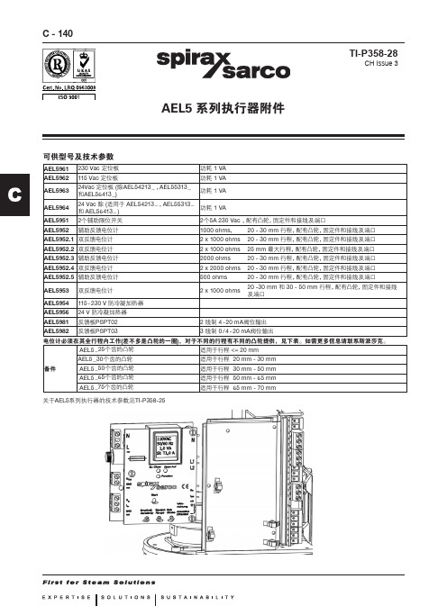
可供型号及技术参数
AEL5961 AEL5962 AEL5963 AEL5964 AEL5951 AEL5952 230 Vac 定位板 115 Vac 定位板 功耗 1 VA 功耗 1 VA
24Vac 定位板 (除AEL54213 _ , AEL55313 _ 功耗 1 VA 和AEL56413 _ ) 24 Vac 除 (适用于 AEL54213 _ , AEL55313 _ 功耗 1 VA 和 AEL56413 _ ) 2个辅助限位开关 辅助反馈电位计 2个5A 230 Vac , 配有凸轮, 固定件和接线及端口 1000 ohms, 2 x 1000 ohms 2 x 1000 ohms 2000 ohms 2 x 2000 ohms 500 ohms 2 x 1000 ohms 20 - 30 mm 行程, 配有凸轮, 固定件和接线及端口 20 - 30 mm 行程, 配有凸轮, 固定件和接线及端口 25 mm 最大行程, 配有凸轮, 固定件和接线及端口 20 - 30 mm 行程, 配有凸轮, 固定件和接线及端口 20 - 30 mm 行程, 配有凸轮, 固定件和接线及端口 20 - 30 mm 行程, 配有凸轮, 固定件和接线及端口 20 -30 mm 和 30 - 50 mm 行程, 配有凸轮, 固定件和接线 及端口
C - 141
接线图
(注:X0,X4,X5,X6X6 1 2 3 4 5 6
AEL5952反馈电位计和 AEL5953 第1个输出
X4 16 14 15
X11
1 棕
2 绿
3 白
回缩位置
伸张位置
伸张位置 回缩位置
电动执行器操作手册
AUMA A-Series 工业电动执行器说明书

Technical InstructionsDocument No. A6V12035775July 7, 2020A-Series IndustrialElectric Actuators AUMA (21,300 and 40,680 lb-in)Siemens Industry, Inc.DescriptionA-Series Industrial Electric AUMA actuators provide precise, durable control of quarter turn Siemens resilient seat butterfly valves. The compact industrial housing is rated to NEMA 6P (IP 68) standards for outdoor use. All models include integrated controls and a manual override handwheel.The standard AUMA models are 120V single phase. All AUMA actuators include six auxiliary switches, torque switches, a position indicator and a heater. Modulating units provide position feedback as standard. Features• Compact, lightweight design and direct mounting • Manual, declutchable override handwheel • Position and motion indicator lights • Push button controls • CE Certified• On/off or modulating control• Output torque 21,300 lb-in (2,407 Nm) to 40,680 lb-in (4,596 Nm) • ISO 5210 for direct mounting• All actuators include a heater to prevent condensation build-up •All modulating units include a feedback potentiometerOrderingActuators can be ordered separately or together with a valve as an assembly.Product NumbersTable 1. A-Series AUMA Industrial Electric Actuators, 120V.Product Number Operating Mode Voltage 50/60 HzTorque 90° Stroke Time*Current Draw (Amps) (lb-in) (Nm) Full Load LockedRotorA226.21K On/Off120 Vac21,300 2,407 60 sec.6.514A226.41K 40,680 4,596 A266.21K Modulating21,300 2,407 A266.41K40,6804,596* Operating times shown are with 60 Hz power supply. Actuators with 50 Hz power supply will be 20% slowerWarning/Caution Notations WARNING: Personal injury or loss of life may occur if you do not perform a procedure as specified.CAUTION:Equipment damage may occur if you do not perform a procedure as specified.Technical Instructions A-Series Industrial Electric Actuators AUMA Document Number A6V12035775June 15, 2020CAUTION:Do not install or use the A-Series Industrial Electric Actuator in or near environmentswhere corrosive substances or vapors could be present. Exposure of the electricactuator to corrosive environments may damage the internal components of thedevice and will void the warranty.Application These actuators are ideal for use on valves for chillers, cooling towers, boilers, heatexchangers and other outdoor applications. The actuators’ advanced electronicsassure reliable compatibility with virtually any analog control signal used in today’sbuilding automation and temperature control systems. The NEMA 6P rated housingprevents any water ingress in outdoor applications. The built-in heater prevents anycondensation build-up inside the housing.NOTE: Use a “liquid tight” conduit connector to maintain NEMA 6P rating. SpecificationsOperating Conditions Ambient Temperature -22°F to 158°F (-30°C to 70°C)Fail Position Loss of supply power - fail-in-placeDuty Cycle On/Off – 15 min. continuous, max. six starts/minuteModulating – 25% intermittent duty Physical Description Motor 120 Vac, Single-Phase, Reversible, PermanentSplit Capacitor Induction MotorMotor Protection 1 Ph-1 thermal switch 284°F (140°C)Class F insulation, tropicalized windingControl Voltage A226.21K and A226.41K: 120 VacA266.21K and A266.41K:Input 4 to 20 mAModular Power Supply 24 VdcOutput Aux. Voltage A226.21K and A226.41K: 115 Vac – 30 mAA266.21K and A266.41K: 24 Vdc – 100 mAFeedback Signal 4 to 20 mAOutput Contacts 6 Output contacts: 6 NO/NC without common 5AOutput Signals Default setting: Fault, End pos. CLOSEDEnd pos. OPEN, Selector sw. REMOTE, Torquefault CLOSE, Torque fault OPENTerminal StripPower Terminals 8 to 10 AWG (6 to 10 mm2)Controls Contacts 14 AWG (2.5 mm2)Heater 24V Internal Supply (5 Watt)Dimensions See Figure 3 and Figure 4.Weight A2x6.21K – 165 lbs. (75 kg)A2x6.41K – 195 lbs. (88 kg)Enclosure NEMA types 6P (IP68)Corrosion Protection: KSConduit entries Plug/socket 100 mm, 2 × 3/4” NPT; 1 × 1-1/4” NPTManual operation To close the valve, turn handwheel clockwise.Drive shaft (valve) turns clockwise in closedirection. 52:1 drive ratioAngle of Rotation 92° maximumCertifications CE CertifiedCSA - Classes C322102 and C3221812(available upon request)A-Series Industrial Electric Actuators AUMA Technical InstructionsDocument Number A6V12035775July 7, 2020Product NumbersTable 2. Product Numbers.Use the product numbers in the following table to order a valve or a valve and actuator assembly. The valve product number consists of the type, action, valve size, disc type, and valve configuration.To order an assembly, add a (-) after the valve product number and then choose the application, actuator, voltage, control signal, end switches followed by a separator (.) and the actuator torque.Siemens Industry, Inc. Page 3Technical InstructionsA-Series Industrial Electric Actuators AUMADocument Number A6V12035775 July 7, 2020Page 4Siemens Industry, Inc.Mounting and InstallationAll A-Series industrial electric actuators are suitable for direct mounting on Siemens resilient seat butterfly valves.NOTE:The standard mounting position for the actuator is to orient the base of the actuator parallel to the pipeline. •To mount an actuator on a vertical pipe, position the unit with the conduit entries on the bottom to prevent condensation from entering the actuator through its conduits.• Use a “liquid tight” conduit connector to maintain NEMA 6P rating.Service The resilient seat butterfly valve and actuator are maintenance-free.WiringCAUTION: •When wiring an A-Series Industrial Electric Actuator for two-position(on/off) control and the power to the actuator is commanded to be off, you must ensure that there is no extraneous or leakage voltage between hot and common. Leakage voltage greater than 3 Vac can cause actuator failure.• When wiring an A-Series Industrial Electric Actuator for two-positioncontrol, the controller should use at minimum a one-second time delay for command signal reversal. Instantaneous command reversals may cause actuator failure.Figure 1.. On/Off .NOTE:Use this A-Series Industrial Electric Actuator only to control equipment under normal operating conditions. Where failure or malfunction of the electric actuator could lead to personal injury or property damage to the controlled equipment or other property, additional precautions must be designed into the control system. Incorporate and maintain other devices such as supervisory or alarm systems or safety or limit controls intended to warn of, or protect against, failure or malfunction of the electric actuator.Figure 2. Modulating.A-Series Industrial Electric Actuators AUMA Technical InstructionsDocument Number A6V12035775July 7, 2020 Information in this publication is based on current specifications. The company reserves the right to make changes in specifications and models as design improvements are introduced. Products or company names mentioned herein may be the trademarks of their respective owners. © 2020 Siemens Industry, Inc.Siemens Industry, Inc. Smart Infrastructure1000 Deerfield Parkway Buffalo Grove, IL 60089 USA + 1 847-215-1000Your feedback is important to us. If you havecomments about this document, please send themto***************************************Document No. A6V12035775Printed in the USAPage5of 5DimensionsFigure 3. Model A2x6.21K Actuators.Figure 4. Model A2x6.41K Actuators.。
电动执行器型号EA 21、EA 31、EA 42 数据表说明书

1Datasheet Electric Actuators Type EA 21 EA 31 EA 42AdvantagesCombinationsEA 21 with 2- or 3-Way Ball ValveEA 31 with 2 Way Ball Valve up to DN 100 EA 31 with Butterfly Valve Type 567 / 568 EA 42 with Butterfly Valve Type 567 / 568Type EA 21, EA31, EA42Rated voltage Allowable humidity AC: 100 - 230 V, 50/60Hz Max. 90 % relative humidity, non condensing AC/DC: 24 V, 56/60 Hz Housing materialsRated voltage tolerancePP fiberglass reinforced, flame retardant, externalstainless steel screws± 10% AccessoriesElectric impedanceFail-safe unit including battery 230 V, 100 k Ω Heating element 24 V, 4.7 k Ω Additional limit switches Ag-Ni, Au, NPN, PNPProtection classMonitoring print with optional: 65 2)per EN 60529 UL /USA: Indoor use - Cycle time extension- Cycle time monitoringPollution grade- Monitoring a selected maximum number of cycles 2 per EN 61010-1 - Monitoring a selected maximum motor currentOverload protection- Position feedback signal 4-20 mA Current/ time dependent (resetting) Position signalization for 4-20 mA feedbackOverload categoryPositioner II Testing adapter RS 232Ambient temperatureAS Interface modul -10° to +50°C 1)EA21 EA31 EA42Rated OutputAC: 40 VA at 100 - 230 V AC: 40 VA at 100 - 230 V AC: 60 VA at 100 - 230 V AC/DC: 24 VA at 24V AC/DC: 32 VA at 24V AC/DC: 40 VA at 24V Nominal torque Mdn (peak)10 (20) Nm 60 (120) Nm 100 (250) Nm Duty cycle at 25°C / 15 min100%, reduced for UL certification50% 35%Control time s/90° at Mdn 5 s 15 s 20 sConnectorsF05 F07 F07 Cycles at 20°C and Mdn250000 100000 75000 Weight2.193 kg3.536 kg4.995 kg Actuating anglemax. 180°, set to 90°1) For temperatures below – 10 °C as well as condensation, the heating element should be built in 2) Protection rating IP67 when used with cable glands and vertical installation.- Simple handling- Robust PP-GF housing with great chemical resistance- Long life time due to roust concept and the choice of best electronic - Universal use thanks to wide rang power supply and standard interfaces - Flexible configuration thanks to the modular concept - Integrated position indicator- Integrated emergency manual override- Numerous controlling and monitoring opportunities2CombinationsElectric actuated Ball ValvesElectric actuated valves type 130 - 135 are based on the ball valve type 546 with the electric actuator EA21 (DN10-DN50) or EA31 (DN65-DN100). These types are made for applications with special process requirements . Ball Valve Electric Electric Actuator Manual Ball Valve Dimensions Materials Standards Type 130 EA 21/31 Type 546 DN 10 - DN 100 PVC-U, PVC-C, ABS, ISO/DIN Type 131 EA 21/31 Type 546 DN 10 - DN 100 PP all standards Type 132 EA 21 Type 546 DN 10 - DN 50 PVDFall standards Type 133 EA 21/31 Type 546 DN 10 - DN 100 PVC-U, PVC-C, ASTM/ANSI Type 134 EA 21/31 Type 546 DN 10 - DN 100 PVC-U, ABS,BS Type 135EA 21/31Type 546DN 10 - DN 100PVC-U, PVC-C, PP, PVDFJISElectric actuated valves type 185 - 188 are based on the ball valve type 543 d16DN10 up to d63DN50 and the electric actuator EA21. These types are modular upgradeable for mixing or diverting applications which demand special process requirements. Ball Valve Electric Electric Actuator Manual Ball ValveDimensionsMaterialsStandardsType 185EA 21Type 543 horizontal DN 10-DN 50PVC-U, PVC-C,ABSall standardsType 186 EA 21 Type 543 horizontal DN 10-DN 50 PROGEF DIN/ISO, ASTM Type 187 EA 21 Type 543 horizontal DN 10-DN 50 SYGEFDIN/ISO, ASTM Type 188 EA 21 Type 543 vertical DN 10-DN 50 PVC-U, ABSDIN/ISO, JISElectric actuated Butterfly ValvesThe electric actuated wafer butterfly valve type 140 offer a wide variety of applications. Due to an optional positioner it can be used as an on / off valve as well as a precise flow control valve.The electric actuated lug butterfly valves type 141/142 offer a wide variety of applications. Due to an optional positioner it can be used as an on / off valve as well as a precise flow control valve.Butterfly ValveElectric Electric Actuator Manual ButterflyValve Dimensions Materials StandardsType 140 EA31/EA42 Type 567 DN 50 - DN 300all all standards Type 141 EA31/EA42 Type 568 DN 50 - DN 200all ISO/DIN Type 142 EA31/EA42Type 568DN 50 - DN 200all ANSI3The metal butterfly valves type 037E / 038E / 039E can be used as open/close or control valve. The easy installation of the valve between pipe flanges warrants reliable operation and sealing. The Rilsan ®-coating of the valve body and the ductile iron disc provide a high resistance against corrosion. The butterfly valves are also available in a standard version with stainless steel disc.Butterfly Valve Electric Electric Actuator Manual Butterfly Valve Dimensions StandardsType 037E EA31/EA42 Type 037 Wafer style DN 50 - DN 300 all standards Type 038E EA31/EA42 Type 038 Lug style DN 50 - DN 300 ISO/DIN; BS, ASTMType 039EEA31/EA42 from DN 350: AumaType 039 Wafer styleDN 50 - DN 1200all standardsExploded viewDimensionsL1 L2 L3 L4 L5 L6 L7 L8 L9 H1 H2 H3mm mm mm mm mm mm mm mm mm mm mm mm EA21 150 83108 6412216493333 167 20189EA31 150 83108 6412216493333 190 25212EA42150 83108 6412216493333 208 252301. Limit switches S1 and S2 6. Electrical supply unit, without protection against accidental contact2. Direct current motor7. Shaft for emergency manual override 3. Optical position indicator 8. Connections for DIN plug or cable gland 4. Plug for accessories9. Assembly bolt for accessories 5. Terminal strip for external connections max. 1.5 mm²Wiring diagramPlanning FundamentalsThe following link will lead you to the Georg FischerPlanning Fundamentals. These detailed documents willsupport you by choosing the right valve for yourapplication./content/gfps/com/en/support_and_services/planning_assistance/planning_fundamentals.html?lang=en4。
AM AE系列智能型角行程电动执行机构 说明书
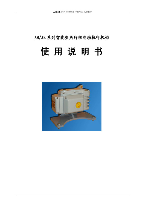
AM/AE系列智能型角行程电动执行机构 使 用 说 明 书一、产品用途AMR/AER 系列一体化智能型电动执行器是采用先进的智能数字控制技术,无需另外配置反馈单元和伺服放大器,可直接接收工业控制仪表或计算机输出的4-20mA.信号,对各种工业球阀、蝶阀或转动装置实现0-90°范围内准确位置定位和控制。
该产品不仅提高了电动执行机构位置控制的精度,而且实现了小型化、智能化、一体化(控制器与执行机构合为一体)。
与传统的电动执行机构相比,具有体积小、重量轻、扭矩大、精度高、功能强、性能可靠、运转成本低、不需维护保养等特点,可广泛应用于电站、石油、化工、冶金、医药、轻工等行业。
产品分为普通型和防爆型,两者外型安装尺寸相同.适用于含有IIC 类爆炸性气体环境中,温度级别为CT6。
二、规格与型号本产品有开关式和调节式两大系列。
开关式电动执行机构主要用于两位式位置定位和控制,无需配置EVP 系列智能控制器。
调节式电动执行机构主要用于连续角位移转动,在0-90°范围内任意位置的定位和控制,要求配置EVP 系列智能控制器。
产品具体规格和型号分别见表1和表2开关式电动 执行机构型号 AER-10AER-25 AER-60 AER-160 AER-250 AER-400 AER-600 输出轴力矩(N.m) 1002506001600250040006000调节式电动*普通调节型可选配红外遥控型智能控制器(内置式)防爆调节型可选配远红外智能控制器(外置式)。
三、主要技术性能·电 源:交流220V±10%,50Hz60Hz ·控制精度:0.5%-3.1%可设·输入信号:4-20mA DC 或1-5V DC ·输入阴抗:200Ω·位置反馈信号:光电隔离输出4-20mA DC 对应执行机构全闭至全开或全开至全闭 ·位置反馈电阻:500Ω-1KΩ ·定位方式选择:手动自动·作用方式选择:正作用/反作用 ·自动定位标定:全开/全闭 ·开关触点容量:交流250V,4A·安全位置选择:输入信号故障时电动执行机构所处位置可选为全开/停止/全闭执行机构型号 AMR-10 AMR-25 AMR-60 AMR-160 AMR-250 AMR-400 AMR-600 输出轴力矩(N.m)1002506001600250040006000·保护功能:内置过热保护器,同时具有软件、电气和机械三重限位保护。
执行器说明书

!
mm F
EB 4 EB 5 EB 6 EB 8 EB 10 EB 12 EB 265 EB 270 EB 280 * F04 F05 F05/07 F07/10 F07/10 F12 F12/16
EB 4 - EB 12
G
11 11/14 14/17 17/22 17/22 27 32/36
H H1 H2 J K
72 67 62 59 54 45 147 137 127 119 109 92 244 227 210 202 185 161 511 473 436 420 382 328 830 774 719 682 626 533 1299 1194 1088 1051 838 1928 1852 1772 1635 1331 3891 3737 3581 3300 2686
!G
kg ! 1 !"#$"%&' NL/
!"
EB 5
3.00 0.15 0.26
EB 6
5.00 0.20 0.58
EB 8
4.30 0.45 1.13
EB 10
14.30 0.50 1.70
EB 12
25.40 0.70 2.79
EB 265
26.00 <2.0 2.70
EB 270
45.00 <5.0 9.00
L
273 326 389 526 656 -
L1
317 145 510
L2
317 510 510
N
80 130 130 130 130 80 130 130
P
30 30 30 30 30 30 30 30
R
85 100 130
汽轮机rexa执行器deh系统(系统简介)

图3 REXA执行器控制模块外型图
图4 REXA执行器动力模块外形图
REXA执行器
工作原理
智能可控电机接受控制模块的功能指令,控制动力模块,以线性位 移大力矩输出,驱动被控对象,同时通过自身位移反馈,完成调节 过程,实现各种功能控制。
电机
液压 系统
动力模块
功能指令
反馈信号
位置反馈
控制 模块
输出
控制输入信号
力驱动执行机构 结构
DEH信号 OPC电磁阀
REXA执行器 杠杆
控制连杆
压力油
错油门
油动机
图8 REXA执行器反向驱动力驱动执行机构
力驱动执行机构 结构
第三种结构:REXA执行器力驱动单侧作用油缸执行机构(图9)
根据系统工作原理和结构要求,可采用REXA执行器正向驱动或 反向驱动力执行机构,与单侧作用油缸组成REXA执行器力驱 动单侧作用油缸执行机构,其工作原理与第一、二种结构基本 相同。
3. 控制系统 标准配置
PC
PC
冗余控制器
终端匹配电阻50Ω RIO分支器
冗余RIO网 10Base 10Mbps
RIO分支器 同轴电缆
终端匹配电阻50Ω
用户终端
(编程与监控)
,
冗余管理控制网 TCP IP 100 Mbi
热备连接电缆 同轴电缆
RIO分站# 1
RIO 分站
I /O
I /O
I/ O
I/O
力驱动执行机构 工作原理
(2)减负荷过程: REXA执行器接受DEH控制信号向上动作,杠杆以油动机活塞杆 为支点,带动控制连杆向上移动,错油门滑阀在其下部高压油的 作用下,跟随上移偏离中间位置,使油动机在压力油的作用下向 关闭方向位移,控制调速汽门,在油动机向下移动的过程中,杠 杆以REXA执行器为支点,带动控制连杆下移,使错油门滑阀回 中,完成减负荷过程。
努托克NTE系列电动执行器使用说明书

NUTORK CORPORATIONNTE Series Quarter Turn Electric ActuatorActuators & ValvesVisual Indicator +Handwheel (Option)NTE - 02L ABS EnclosureNTE - 02S TypeInternal MagnetContactor For 24VDC(Option)Modulating TypeStandard TypeApproved by:Low Voltage Directive 2006/95/EC Machinery Directive 2006/42/EC Electromagnetic Compatibility Directive 2004/108/EC5. The captive cover bolt prevents bolt from dropping when cover is opened.1. Due to characteristics of valve, the electric actutor must be able to provide high start up torque with full load whenever the valve is at open, closed or any other position. NUTORK NTE series electric actuators are designed for such working requirement.2. Gear driving unit is made of alloy steel with heat treatment featuring high strength, excellent wear resistance and long term fatigue load impact.3. The crank handle is designed as detachable to minimize the dimension of the actuator.4. The integral construction of the wormgear and drive shaft provides long term dependable operation with high output torque.6. The stainless steel stroke bolt and cam provide 0 - 90° adjustability.7. The tempered glass visual position indicator provides anti-aging, temperature resistance and anti-deformation.8. The epoxy encapsulated control servo unit provides heat insulation, moisture and dust proofing, thus suitable for various industrial process requirements.Electric Actuator – Featuresw w w.n u t o r k.c o m112345678Wiring Diagram18/1609/8018/1609/801261260.28 0.151.2/2.65Weight(Kg/Lbs)Enclosure Mounting DirectionAmbient Temp.Valve ConnectionDimension(mm)ModelPowerOutput Torque(Nm/in.lbs)Operation Speed(sec.)Power Consumption(W)Rated Current(A)Insulation ResistanceWithstand Voltage1.10100M Ω@500VDC Ω100M @250VDC Die-casting aluminum alloy72(W) x 75(L) x 120(H)NTE-02S110/220VAC 24VDC 861500VAC@1 Min.550VAC@1 Min.IP68All directions -30°C ~ +60°CISO5211,9/11mm x F03/F04/F05Housing Material standard accessory, built-in,auto-reset typeThermal Protection w w w.n u t o r k.c o m210235.55016.53638.5729x9 11x11Crank HandleG1/4" with cable gland & 30cm lead wire4-M 68-M5503642Depth:17mmBottom ViewBottom ViewModel : NTE-02S Power Supply 200VAC Rated Current : 0.15A Frequency 50/60Hz Amb Temp : 30℃~60℃Output Torque 18NM Operation Time : 12S Enclosure : IP168Manual OperationCD V 42B: e p y T B :e p y T A :e p y T OLSK CCLSPEMLNBlueRed Black BrownCloseOpnenGreyY&GFull-close signalFull-open signal COM OLS K CCLSPEMLN BlueRed Black WhiteBrown Grey CloseOpen Y&G Full-close signal Full-open signal Full-open signal Full-close signal COMOLS CLSPE MRedBlack White Brown Grey Close OpenY&G D1D2Wiring DiagramType: B 10987654321MACPE NO NCNO NCOLSCLSYellow Green Purple Orange Grey Brown WhiteBlackRedBlueOpenStop Close Type: B1Model Power Output Torque Operation Speed(sec.)Power Consumption(W)Rated Current(A)Insulation Resistance Withstand Voltage Thermal Protection Mounting Direction Ambient Temperature Valve Connection Dimension(LxWxH),mm Enclosure Housing Material Weight(Kg)NTE-02L 24VAC25Nm(222in.lbs)100M Ω@500VDC 1500VAC @ 1 minStandard accessory ,built-in ,auto-reset typeAll Direction -30°C ~ +60°C12x12x12mm square drive shaft x F05160(L)x100(W)x133(H)mmIP65ABS 1.4Kg10 sec.20W 1.118W 0.218W 0.1110VAC 220VACFull-open signal EarthFull-closed signal COM1Full-open signal Full-closed signal COM2COMCrank Handle100351235124M516011013303w w w.n u t o r k.c o mw w w.n u t o r k.c o m4NTE-03NTE-05NTE-10NTE-20NTE-40NTE-60NTE-100NTE-160NTE-200NTE-400NTE-6003015/30/5050/60/10080/100/150/200150/250/300/400600300/800/100016002000400060002010/20/30(std.)15/20/30(std.)9/15/20/30(std.)9/15/20/30(std.)3015/30/50(std.)881001001500-360°0-360°0-90°0-90°0-90°0-90°0-90°0-90°0-90°0-90°0-90°◇14/17-F05/F07◇17/22-F07/F10DC motor 202040409090..............................AC motor 10102340909010010010020020024VDC22 2.48.511.511.811.5........................110VAC 0.480.480.640.92 2.06 2.2 2.2 2.2 4.10 4.10220VAC 0.240.240.320.480.920.95 1.20 1.20 1.20 2.10 2.10380VAC0.150.150.190.250.450.460.480.480.480.900.902.22.2477.87.811.211.511.83131ModelOutput Torque(Nm)Operation Speed (Sec.)@0-90°/ 50Hz Operation Angel(Max.)Power (Watts)Valve Conn./ ISO5211◇9/11-F03/F05or ◇14-F05/F07◇17/22/27-F07/F10◇22/27 - F10/F12or ◇36 - F14/F16Rated Current 50HZ(A)Weight-(Kg)Duty Cycle (ON/OFF)Duty Cycle (Modulating)S4 : 30~50%, 300~1200 Start/HourPower Supply 1 Phase:110/220VAC±10%@50/60Hz, 3 Phase:380/440VAC±10%@50/60Hz, 12VDC.24VDC/VAC S2 : 35%,10min. ~ 30min.Stall Protection standard accessory , built-in , auto-reset type Anti-Vibration XYZ 10g , 0.2~34Hz , 10 minutes Ambient Humidity90%RH Max.(non-condensing)Ambient Temperature -30ºC ~ +60ºC Mounting Direction All DirectionsElectrical Conduit M20×1.5 with cable gland for standard type(2 - M20×1.5 with cable gland for modulating type)7. H : Space heater 8. Torque switches(2 units)9. Various mounting bracketsManual Operation Detachable Crank Allen-Key (standard accessory)StopperIn operation : limit switches at full & closed position ; manual operation:mechanical stopper Housing MaterialDie-casting aluminum alloy Bare Shaft Enclosure Rating IP67(standard), IP68(option)Various Option1. Type A standard type2. Type B additional limit switches (2xSPST) or Type B1 additional limit switches(2xSPDT)3. Type C potentiometer unit (1K Ω or 5K Ω)4. Type D potentiometer unit (1K Ω or 5K Ω) with additional limit switches (2xSPST)5. Type E modulating controller (input signal : 4-20mA or 1-5VDC.output signal : 4-20mA )6. Type F current position transmitter(output signal : 4-20mA)Techanical Data(NTE Series Electric Actuator)Type A: Standard TypeOutput Signal:2xSPST(NO) with line power switchInput Signal:4-20mDC or 0-5VDC Output Signal: 4-20mADCOutput Signal: 4-20mADCOutput Signal: 1xSPST(NO)micro-switch each at open & close position.Output Signal: 1xSPST(NO)micro-switch each at open & close position.Output Signal: 1xSPST(NO)micro-switch each at open & close position.Output Signal: 1xSPDT(NC/NO) micro-switch each at open & close positionOutput Signal:0-500Ω or 0-1000ΩType B: 2xSPST(NO)w w w.n u t o r k.c o m5Type E: Modulating ControlType F: R/I ConverterDC Motor with 2xSPST(NO)3 Phase, 380/415/440VAC Motor with 2xSPST(NO)Type C: PotentiometerType B1: 2xSPDT(NO/NC)blue yellow redbrownblack brown greenwhite brown green RHOXSCXSols cls MTPOPEN-SIGNAL SHUT-SIGNAL NC1NC2COM1COM2OPEN STOPSHUTElectric Actuator - Dimension Tablew w w.n u t o r k.c o m6Model NTE-03NTE-05NTE-10NTE-20NTE-40NTE-60NTE-100NTE-160NTE-200NTE-400NTE-600A A1MMNUTORKRso8-M10soO PTU KAA1HH 1ETNUTORKRsoLBDØFDØGXV 4-Z4-S XV 4-Z4-S PBracket + CouplerBare ShaftBare ShaftBare ShaftISO5211NUTORKRE H H1TK L B X V PSZØG ØF D115221**********12686013836509/11/144-M54-M67028F o l l o w e d b y V a l v e115221**********12686013836509/11/144-M54-M67028123222081241915*15827010550709/11/144-M64-M89035148222581482223*2311884178701024-M84-M101254814/17148222581482223*2311884178701024-M84-M101254817/22148222581482223*2311884178701024-M84-M101254817/2215627.52801592530*30148841871021254-M101356522/2715627.52801592530*30148841871021254-M101356522/2715627.52801592530*30148841871401654-M1617565362664391794852*521801802661592544-M18522664391794852*521801802661592544-M1852NTE Series Quarter Turn Electric Actuatorw w w.n u t o r k.c o m7Ordering InformationA. Output Torque / Operation Time1.Code:02S,(18Nm)-12 sec.8.Code:60,(600Nm)- 30 sec.2.Code:02L,(22Nm)-15 sec.9.Code:100,(1000Nm)-50 sec.3.Code:03,(30Nm)-20 sec.10.Code:160,(1600Nm)-88 sec.4.Code:05,(50Nm)-30 sec.11.Code:200,(2000Nm)-100 sec.5.Code:10,(100Nm)-30 sec.12.Code:400,(4000Nm)-100 sec.6.Code:20,(200Nm)-30 sec.13.Code:600,(6000Nm)-150 sec.7.Code:40,(400Nm)-30 sec.14.Code:XX (the other output Torque & Operation Time)Note: 1. The quick operation speed is available upon request.B. Type(Control function)2.Code B: 1xSPST(NO) micro switch for each at open & close3.Code B1: 1xSPDT micro switch for each at open & close4.Code C: 1K Ω potentiometer5.Code D: 1xSPST,NO micro-switch+ 1K Ω potentimeter C. Power Voltage:1.Code A:24VDC 5.Code E:380VAC 2.Code B:24VAC6.Code F:440VAC 3.Code C:110~120VAC7.Code X: others4.Code D:220~240VACNote: 02S only available in 24/120/240VAC, 24VDC 02L only available 240VACD. Accessories:1.Code: H - Heater(02S is not available)E. Enclosure1.Code:IP67, IP67 enclosure(standard)2.Code IP68: IP68 enclosureNote: 1. 02S only available in type A & B control function 2. 02L only available Type B control function 7.Code F: position transmitter (output signal:4-20mADC)NTEOutput TorqueControlType Power AccessoriesEnclosure6.Code E: modulating control (input/output singal:4-20mADC)1.Code A: StandardNUTORK CORP. manufactures a wide range of pneumatic actuators, electric actuators and theaccessories of pneumatic actuator (limit switchbox, solenoid valve, manual override ---etc.) for quarter turn valvesNutork Corp. supply the following product range:NUTORKNK series rack & pinion type (CE-ATEX certified and PED compliant)14 models, the output torque from 9Nm(80in.lbs) to 3,920Nm(34,660in.lbs) at 6 bar air supply.ISO5211/DIN3337 for valve connection, VDI/VDE 3845(Namur) standard connection for solenoid valve and shaft top end(limit switchbox or E/P positioner), +/-5 degree stroke adjustment. 25~30um standard hard anodizedtreatment on actuator body and over 120um epoxy coated on end caps which meet ASTM B117 qualification(salt spread test over 1,000 hours and no corrosion.PTFE, Polyester, Nickel, Ceramic and Epoxy coated are available on request.NSF series scotch yoke type pneumatic and hydraulic actuators (CE-ATEX certified and PED compliant)The output torque from 978Nm(8,656in.lbs) to 226,200Nm (2,001,870in.lbs) at 6 bar air supply.Anti-corrosion painting on outer body and cylinder as standard. VDI/VDE 3845(Namur) standard connection for shaft top end(limit switchbox or E/P positioner), +/-10 degree stroke adjustment. ISO5211 standard for valve connection. PTFE coated on inner cylinder surface. Hydraulic manual override is available for big size actuator.NTE series electric actuator, CE approval13 models and the output torque from 18Nm(159in.lbs) to 6000Nm(53,106in.lbs), compact design, die-casting aluminum alloy housing, alloy steel with heat treatment gear driving unit, integral wormgear & drive shaft, 30% duty rating, detachable crank handle, ISO5211(option), IP67 enclosure.IP68 for option.NTQ electric actuator, CE approval(IP67 & EExdIIBT4 enclosure)13 models, the output torque from 100Nm(885in.lbs) to 6,000Nm(53,106in.lbs), de-clutchable manual override, 2xSPDT each for open & close, torque switch: 1xSPDT each for open & close. space heater, self-lock, IP67 & EExdIIBT4 enclosure.The fully range accessories(Limit Switchbox, Solenoid Valve,Declutchable Manual Override, Air Filter regulator, E/P Positioner ---etc).NTE-02L Quarter Turn Electric ActuatorOutput torque 25Nm(222in.lbs),operation time 10Sec;voltage 24VAC,110VAC & 220VAC for option,ABS housing,30% duty rating,IP65 enclosure.NUTORK Corp.China Office:No.10,Lane 899, Zhuguang Road, Qingpu Area, Shanghai,ChinaTel*************/59888463/59888436Fax*************Email:*****************USA Office:5010 Wright RD. Suite 200B Stafford, TX 77478Tel: +1-281-222-0018 Email:*********************Website: 。
SMC电动执行器全系列说明+应用

E-MY更新品
Φ 32, 50
LEM Series
Φ 25, 32
微型出杆式、滑台式
LEP Series
出杆式 Φ 6, 10
带导杆式滑台
高刚性
Φ 25
滚珠丝杠/同步带
Φ 40, 63
LEL Series
LEJ Series
1.无杆式 LEFS、LEFB
安装便捷、结构紧凑
本体、滑台均设有安装孔 高、宽度减少50%
步进电机 (DC24V)
LEFS25 LEFS32
滚珠 丝杠
LEFS40 200~1000 直流伺服 (DC 24V) LEFS16 LEFS25 100~400 100~600
LEFS25S 100~600 交流伺服 (100W/200W LEFS32S 100~800 /400W) LEFS40S 200~1000
行业/设备 CP/汽车尾灯螺钉热压机 应用产品 LEF系列无杆式电缸
序号 1 2
型号 LEFS25B-500-R16N1 LEFS16AA-400-R16N1
数量 1 1
应用说明:两条LEF配合,找到螺钉上料位置,然后加热,再放至螺钉安装位 置进行热压工作,总计4个螺钉8个工位。
行业/设备 电子/标记印刷机 应用产品 LEFS系列无杆式电缸
最大负载 水平[kg] 垂直[kg] 1 5 14 1 2
5 15 25 -
最大速度 [mm/s] 48~1100 48~1400 48~1500 48~2000 Max.2000 Max.2000 Max.2000
定位精度 [mm]
±0.1
±0.08
行业/设备 EP/电表检测机 应用产品 LEF系列无杆式电缸
汽车传感器ECU执行器的关系概述

汽车传感器ECU执行器的关系概述1.1 电子控制组件(ECU)ECU以微机为中心。
还包括前置的A/D转换器、数字信号缓冲器以及后置的信号放大器等。
微机运算速度快、精度高,能实时控制,并具备多中断响应等功能。
目前除了8位、16位微机外,32位特别是64位微机已开始逐步使用。
而且,不仅有通用型微机和单片机,专用的汽车微机也已研制出来。
正是微机技术突飞猛进的发展促进了汽车电控技术的不断完善。
可以说,当前 ECU的发展总趋势是从单系统单机控制向多系统集中控制过渡。
不久以后,汽车电控系统将采用计算机网络技术,把发动机电控系统、车身电控系统、底盘电控系统及信息与通信系统等各系统的ECU相联结,形成机内分布式计算机网络,实现汽车电子综合控制。
实物如图1-1所示ECU实物图(1-1)1.2 传感器工作条件非常苛刻的汽车传感器,传感器可以准确地*工作是必不可少的。
近年来,在这一领域,理论研究和材料应用的发展是比较快速的,金属薄膜半导体技术,陶瓷烧结技术的快速发展。
毋庸置疑,智能、集成和数字化将成为未来传感器发展的趋势。
如氧传感器、机构1-2,图1-3中的实物图。
氧传感器结构图(1-2)氧传感器实物图(1-3)1.3 执行器为准确执行器执行由ECU信号发出的命令。
因此,执行器将准确地工作或不影响电子控制的成功或失败,这就是为什么他们的可靠性和准确性一直工作作为一个研究的重点,并吸引了更多的关注。
目前,电动汽车电子控制系统、电磁阀、电机、压电元件、点火、电磁继电器、热电偶、结构和功能各不相同的执行器类型范围。
致动器的发展方向是智能执行器和智能功率固态器件。
总结:电子控制系统由传感器、电子控制单元(ECU)、执行器3部分。
为输入传感器测量物理信号(温度、压力等),将其转换为电信号;ECU的作用是接收来自传感器的输入信号,根据设计方案的计算处理,输出处理结果;执行器ECU根据电气信号输出驱动器使要求的变化。
关系的传感器、计算机、图1-4所示器图(1-4)。
汽车常用执行器

执行器:一种能量转换部件,它能在电子 控制装置的控制下,将输入的各种形式的 能量转换为机械动作。
如:电动机、离合器阀、气门机构、电 磁阀、电磁膜片等。
分类:模拟量执行器和数字量执行器。
电动机
一、概述 电动机特性的要求见书。
二、直流电动机
直流电动机具有良好的调速特性,较大的 起动转矩,相对功率大及快速响应等优点。 在汽车上得到广泛的应用。
EFI主继电器
ISC阀
发动机ECU
蓄电池
丰田皇冠3.0轿车步进电机型ISCV电路
怠速控制阀的控制内容
• 控制内容:
– 起动初始位置的设定 – 起动控制 – 暖机控制 – 怠速稳定控制 – 怠速预测控制 – 电器负荷增多时的怠速
控制 – 学习控制
怠速控制阀的控制内容
起动初始位置的设定:关闭点火开关发动机熄火后,电子 控制单元ECU的M-REL端子向主继电器延续供电2~3s, ECU控制步进电机ISCV全部打开,以利于下次起动。
• 图中画出的是定子为两相集中绕组(AO、 BO), 每 相为两对极, 转子磁钢也是两对极的情况。
• 从图中不难看出, 当定子绕组按A - B - (-A) - (-B) - A …… 轮流通以直流电时, 转子将按顺时针方向 转动, 每次转过45°空间角度, 也就是步距角为 45°。
• 一般来说, 步距角的值为
• 转子磁钢充磁后, 一端(如图中A端)为N极, 则A端转子铁心的整个圆周上都呈N极性, B 端转子铁心则呈S极性。 当定子A相通电时, 定子1 - 3 - 5 - 7极上的极性为N - S - N - S, 这时转子的稳定平衡位置就是图所示的位置,
即定子磁极1和5上的齿在B端与转子的齿对齐, 在A端则与转子槽对齐, 磁极 3 和 7 上的齿与 A端上的转子齿及B端上的转子槽对齐, 而B 相 4 个极(2、 4、 6、 8 极)上的齿与转子齿都 错开1/4齿距。
电动执行器有五种类型
电动执行器有五种类型:直行程电动执行器、角行程电动执行器、电动调节阀、PID电动调节执行器和电磁阀。
前四种属于DDZ型。
下面简要介绍一下直行程电动执行器(DKJ)和角行程电动执行器(DKZ)。
直行程与角行程电动执行器的作用是接收调节器或其它仪表送来的0~10,4~20毫安或1~5伏电压的标准值流电信号,经执行器后变成位移推力或转角力矩,以操作开关、阀门等,完成自动调节的任务。
这两种执行器以前都是由伺服放大器与执行机构两大部分组成的。
现在有机电一体智能化的结构,它们的结构、工作原理和使用方法都是相似的,区别仅在于,一个输出位移(推力),一个输出转角(力矩)。
电动执行器选型考虑要点一、根据阀门类型选择电动执行器阀门的种类相当多,工作原理也不太一样,一般以转动阀板角度、升降阀板等方式来实现启闭控制,当与电动执行器配套时首先应根据阀门的类型选择电动执行器。
1.角行程电动执行器(转角<360度)电动执行器输出轴的转动小于一周,即小于360度,通常为90度就实现阀门的启闭过程控制。
此类电动执行器根据安装接口方式的不同又分为直连式、底座曲柄式两种。
a)直连式:是指电动执行器输出轴与阀杆直连安装的形式。
b)底座曲柄式:是指输出轴通过曲柄与阀杆连接的形式。
此类电动执行器适用于蝶阀、球阀、旋塞阀等。
2.多回转电动执行器(转角>360度)电动执行器输出轴的转动大于一周,即大于360度,一般需多圈才能实现阀门的启闭过程控制。
此类电动执行器适用于闸阀、截止阀等。
3.直行程(直线运动)电动执行器输出轴的运动为直线运动式,不是转动形式。
此类电动执行器适用于单座调节阀、双座调节阀等。
二、根据生产工艺控制要求确定电动执行器的控制模式电动执行器的控制模式一般分为开关型(开环控制)和调节型(闭环控制)两大类。
1.开关型(开环控制)开关型电动执行器一般实现对阀门的开或关控制,阀门要么处于全开位置,要么处于全关位置,此类阀门不需对介质流量进行精确控制。
执行器特性(1)

L K2
- Mf
lf
Ff
Kf
2021/7/28
35
Io
Fi
Mi
Ki
li
+
Pa
L
K1
K2
- Mf
Ff
lf
Kf
L I0
Kili
K1K2 1K1K2Kflf
K1K2 K f l f 1
K li i K f lf
阀杆位移和输入信号之间的关系取决于转换系数Ki、力臂长度li以及反馈部
分的反馈系数Kf,而与执行机构的时间常数和放大系数,即执行机构的膜 片有效面积和弹簧刚度无关,因此阀门定位器能消除执行机构膜片有效面 积和弹簧刚度变化的影响,提高执行机构的线性度,实现准确定位。
2021/7/28
5
2021/7/28
6
2021/7/28
7
(2) 等百分比流量特性(对数流量特性)
单位相对位移变化所引起的相对流量变化与此点的相对流量成正比关系
d( Q )
Qmax d( l )
k Q Qmax
L
Q
( l 1)
R L
Qmax
特点:a. Q ↑放大系数↑
b. 流量相对变化值是常数
(1)串联管道时
* 可调比减小
* 流量特性发生畸变 直线特性→快开特性 等百分比特性→直线特性
2021/7/28
11
(2)并联管道时的工作流量特性
可调比将大大下降 通常一般X 值不能低于0.8, 即旁路流量只能为总流量的百分数之十几。
2021/7/28
12
3. 调节阀的可调比
可调比R反映调节阀的调节能力的大小
: g / cm 3
2021/7/28
380vac电动执行器技术参数

380vac电动执行器技术参数摘要:1.380vac 电动执行器概述2.380vac 电动执行器技术参数2.1 功率2.2 电压2.3 驱动方式2.4 工作环境2.5 控制方式2.6 信号接口2.7 安全性能正文:一、380vac 电动执行器概述380vac 电动执行器是一种采用交流电压驱动的电动执行器,适用于各种工业自动化控制系统。
它可以接收来自控制系统的信号,实现对阀门、风门等设备的精确控制,以达到调节流量、压力、温度等参数的目的。
二、380vac 电动执行器技术参数1.功率380vac 电动执行器的功率根据其型号和规格而有所不同。
一般来说,功率越大,执行器的驱动能力越强,可以控制的设备范围也越广。
2.电压380vac 电动执行器的电压为380 伏特交流电,符合我国工业用电标准。
在使用过程中,需要注意与电源电压的匹配,以确保执行器的正常工作。
3.驱动方式380vac 电动执行器采用交流电机驱动,具有稳定的转速和较大的驱动力。
根据不同的应用场景,可以选择齿轮驱动、皮带驱动等方式,以满足不同设备的控制需求。
4.工作环境380vac 电动执行器适用于各种工业环境,如石油、化工、电力、水处理等。
但在高温、潮湿、腐蚀等恶劣环境下,需要选择具有特殊防护措施的执行器,以保证其正常工作和延长使用寿命。
5.控制方式380vac 电动执行器可以接受来自控制系统的模拟量或数字量信号,实现对设备的精确控制。
同时,执行器还可以通过内置的PID 调节功能,对控制过程进行自适应调整,以提高控制精度和稳定性。
6.信号接口380vac 电动执行器通常提供4-20mA、0-10V 等标准信号接口,便于与上位控制系统连接。
此外,部分执行器还可以支持无线通信、以太网通信等现代通信方式,以满足更为复杂数字通信需求。
7.安全性能380vac 电动执行器的安全性能主要包括防爆、防水、防腐、防尘等功能。
在易燃易爆场合,应选择具有防爆认证的执行器,以确保设备和人员的安全。
