Bray92-93气动执行器
EB8.1SYD型德国EBRO气动执行器的工作原理
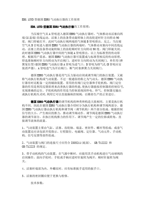
EB8.1SYD型德国EBRO气动执行器的工作原理EB8.1SYD型德国EBRO气动执行器的工作原理:当压缩空气从A管咀进入德国EBRO气动执行器时,气体推动双活塞向两端(缸盖端)直线运动,活塞上的齿条带动旋转轴上的齿轮逆时针方向转动90度,阀门即被打开。
此时气动执行阀两端的气体随B管咀排出。
反之,当压缩空气从B官咀进入德国EBRO气动执行器的两端时,气体推动双塞向中间直线运动,活塞上的齿条带动旋转轴上的齿轮顺时针方向转动90度,阀门即被关闭。
此时德国EBRO气动执行器中间的气体随A管咀排出。
以上为标准型的传动原理。
根据用户需求,德国EBRO气动执行器可装置成与标准型相反的传动原理,即选准轴顺时针方向转动为开启阀门,逆时针方向转动为关闭阀门。
单作用(弹簧复位型)德国EBRO气动执行器A管咀为进气口,B管咀为排气孔(B管咀应安装消声器)。
A管咀进气为开启阀门,断气时靠弹簧力关闭阀门。
德国EBRO气动执行器是用气压力驱动启闭或调节阀门的执行装置,又被称气动执行机构或气动装置,不过一般通俗的称之为气动头。
德国EBRO气动执行器有时还配备一定的辅助装置。
常用的有阀门定位器和手轮机构。
阀门定位器的作用是利用反馈原理来改善执行器的性能,使执行器能按控制器的控制信号,实现准确的定位。
手轮机构的作用是当控制系统因停电、停气、控制器无输出或执行机构失灵时,利用它可以直接操纵控制阀,以维持生产的正常进行。
德国EBRO气动执行器的调节机构的种类和构造大致相同,主要是执行机构不同。
因此在德国EBRO气动执行器介绍时分为执行机构和调节阀两部分。
德国EBRO气动执行器由执行机构和调节阀(调节机构)两个部分组成。
根据控制信号的大小,产生相应的推力,推动调节阀动作。
调节阀是德国EBRO气动执行器的调节部分,在执行机构推力的作用下,调节阀产生一定的位移或转角,直接调节流体的流量。
1、气动装置主要由气缸、活塞、齿轮轴、端盖、密封件、螺丝等组成;成套气动装置还应该包括开度指示、行程限位、电磁阀、定位器、气动元件、手动机构、信号反馈等部件组成。
美国博雷蝶阀执行机构博雷阀门产品系列及配件

美国博雷蝶阀执行机构博雷阀门产品系列及配件美国博雷(BRAY)是一家领先的阀门制造商,专门设计和生产高品质的蝶阀和执行机构。
他们的产品系列广泛应用于化工、石油、天然气、水处理等行业。
博雷阀门产品系列包括以下几种类型的阀门:1.蝶阀:蝶阀是博雷的主打产品之一、它由一个圆形阀体和一个旋转的阀盘组成,通过旋转阀盘来控制介质流量。
博雷的蝶阀具有结构简单、体积小、重量轻、操作灵活等特点。
蝶阀通常用于介质流量调节和切断。
3.电动执行器:电动执行器是一种电动操纵装置,用于远程操控阀门。
博雷的电动执行器采用先进的电动控制技术,具有精准的控制能力和可靠的性能。
它们通常用于需要频繁操作或远程控制的应用。
4.气动执行器:气动执行器是一种通过气动力来操作阀门的装置。
它们通常由气动活塞、气动马达或其他气动组件组成。
博雷的气动执行器具有快速响应、可靠性高、维护方便等优点。
它们通常用于高压或大流量的应用。
博雷阀门产品系列的配件包括以下几种类型:1.阀座:阀座是蝶阀的一个重要组成部分,用于密封阀盘和阀体之间的空间。
博雷的阀座采用耐磨材料制成,具有优异的密封性能和耐久性。
2.传动装置:传动装置是用于传输动力的装置,将执行机构动力传递给阀门。
博雷的传动装置通常采用链传动、齿轮传动等机构,具有高效率、低噪音、平稳传动等特点。
3.连接件:连接件用于连接阀门和管道,通常包括法兰、螺纹、焊接等类型。
博雷的连接件采用高强度材料制成,具有可靠的连接性能和完善的密封性能。
总之,美国博雷(BRAY)提供的蝶阀、执行机构和配件具有高品质、可靠性和灵活性。
他们的产品适用于各种应用场景,可以满足客户的不同需求。
气动执行器结构及原理

气动执行器结构及原理 The final edition was revised on December 14th, 2020.气缸结构与原理学习气动执行机构气动执行机构俗称又称气动执行器(英文:Pneumatic actuator )按其能源形式分为气动,电动和液动三大类,它们各有特点,适用于不同的场合。
气动执行器是执行器中的一种类别。
气动执行器还可以分为单作用和双作用两种类型:执行器的开关动作都通过气源来驱动执行,叫做DOUBLE ACTING (双作用)。
SPRING RETURN (单作用)的开关动作只有开动作是气源驱动,而关动作是弹簧复位。
气动执行机构简介气动执行器的执行机构和调节机构是统一的整体,其执行机构有薄膜式、活塞式、拨叉式和齿轮齿条式。
活塞式行程长,适用于要求有较大推力的场合;而薄膜式行程较小,只能直接带动阀杆。
拨叉式气动执行器具有扭矩大、空间小、扭矩曲线更符合阀门的扭矩曲线等特点,但是不很美观;常用在大扭矩的阀门上。
齿轮齿条式气动执行机构有结构简单,动作平稳可靠,并且安全防爆等优点,在发电厂、化工,炼油等对安全要求较高的生产过程中有广泛的应用。
齿轮齿条式:齿轮齿条:活塞式:气动执行机构的缺点控制精度较低,双作用的气动执行器,断气源后不能回到预设位置。
单作用的气动执行器,断气源后可以依靠弹簧回到预设位置工作原理说明班当压缩空气从A管咀进入时,气体推动双活塞向两端(缸盖端)直线运动,活塞上的齿条带动旋转轴上的齿轮逆时针方向转动90度,阀门即被打开。
此时气动执行阀两端的气体随B管咀排出。
反之,当压缩空气从B官咀进入气动执行器的两端时,气体推动双塞向中间直线运动,活塞上的齿条带动旋转轴上的齿轮顺时针方向转动90度,阀门即被关闭。
此时气动执行器中间的气体随A管咀排出。
以上为标准型的传动原理。
根据用户需求,气动执行器可装置成与标准型相反的传动原理,即选准轴顺时针方向转动为开启阀门,逆时针方向转动为关闭阀门。
拨叉式气动执行器结构原理
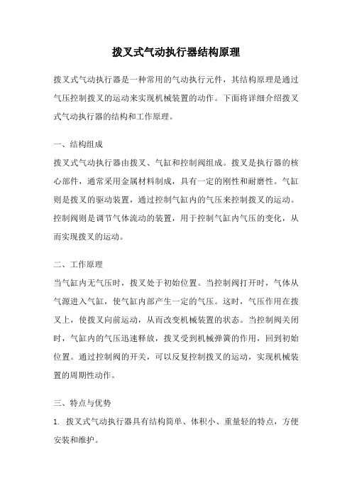
拨叉式气动执行器结构原理拨叉式气动执行器是一种常用的气动执行元件,其结构原理是通过气压控制拨叉的运动来实现机械装置的动作。
下面将详细介绍拨叉式气动执行器的结构和工作原理。
一、结构组成拨叉式气动执行器由拨叉、气缸和控制阀组成。
拨叉是执行器的核心部件,通常采用金属材料制成,具有一定的刚性和耐磨性。
气缸则是拨叉的驱动装置,通过控制气缸内的气压来控制拨叉的运动。
控制阀则是调节气体流动的装置,用于控制气缸内气压的变化,从而实现拨叉的运动。
二、工作原理当气缸内无气压时,拨叉处于初始位置。
当控制阀打开时,气体从气源进入气缸,使气缸内部产生一定的气压。
这时,气压作用在拨叉上,使拨叉向前运动,从而改变机械装置的状态。
当控制阀关闭时,气缸内的气压迅速释放,拨叉受到机械弹簧的作用,回到初始位置。
通过控制阀的开关,可以反复控制拨叉的运动,实现机械装置的周期性动作。
三、特点与优势1. 拨叉式气动执行器具有结构简单、体积小、重量轻的特点,方便安装和维护。
2. 气动执行器的驱动力源来自气压,无需外接电源,能够适应恶劣的工作环境。
3. 气动执行器的响应速度快,可靠性高,能够实现快速准确的动作。
4. 气动执行器的控制方式灵活多样,可以通过手动控制、电气控制、自动化控制等方式进行控制。
5. 气动执行器的运行成本低,气源易得,能耗小,具有较高的经济性。
四、应用领域拨叉式气动执行器广泛应用于各个领域的自动化设备中,如机床、包装设备、输送设备、装配线等。
其主要作用是控制和驱动机械装置的运动,实现自动化生产过程中的工序转换、零部件装配、产品检测等功能。
拨叉式气动执行器的快速响应、稳定可靠的特点,使其成为自动化生产中不可或缺的重要元件。
总结:拨叉式气动执行器通过控制气压来实现拨叉的运动,从而改变机械装置的状态。
其结构简单、体积小、重量轻,并具有快速响应、稳定可靠的特点。
拨叉式气动执行器广泛应用于各个领域的自动化设备中,为实现自动化生产提供了重要的驱动装置。
美国博雷(BRAY)蝶阀 执行机构 博雷阀门产品系列及配件
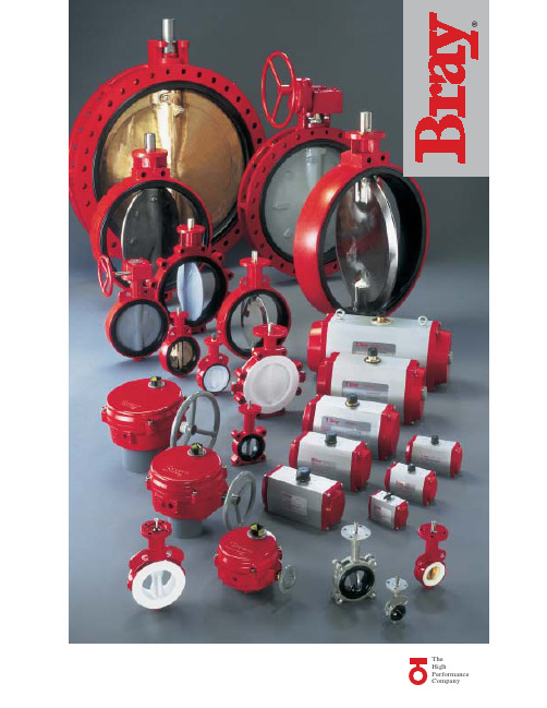
70系列电动执行机构亦可提供应 用于流量控制阀门的精确定位。这 一系列阀门的配置为可接收模拟输 入信号的电路板或串行通讯总线, 如DeviceNet。
手动执行器
S1手柄及齿盘
博雷提供两种手柄用于 开关和调节,一种用于1"12"(25mm-300mm)弹性阀 座阀门,另一种用于2-1/2" -8"(65mm-200mm)高压阀 门的大扭拒手柄。90°回转 手柄具有弹簧锁定功能和 指示阀板位置的方向指示 针。同时提供带螺栓的阀 板。对于弹性阀座齿盘有 10个位置是标准的。对于 高压阀齿盘有八个位置是 标准的。两种阀门都配有 限位开关以防阀门旋转过度。另外 提供非限位位置板,180°槽板,一 个记忆限位及一个2"方形螺帽。
博雷忠实服务于客户。我们的 员工训练有素,对博雷各类产品了 如指掌,给予客户一对一的服务。 此外,博雷还有经验丰富的经销商, 在世界范围内为我们的客户提供优 质服务。
根据博雷标准设计的产品系列 具有极高的兼容性、经济性,性能 优异,为现代工业的应用提供了优 质的选择。
弹性衬胶阀门 博雷提供的全系列弹性 衬胶蝶阀应用广泛,性能 可靠,经久耐用。 其 独 特 性 在 于 , 我 们 的 阀门能够与绝大多数法兰 标准兼容。因此,同一种阀门可 适应不同市场的需求。另一个特 性是我们的舌槽式阀座设计可以 完全阻隔流体渗入阀体和阀杆。 大多数标准阀体使用聚酯涂层确 保了良好的防腐性能并且阀门表 面不易受到磨损。博雷阀门在颈 部均有加长设计,与管线至少有 50mm的距离。阀门顶盘连接法兰 符合ISO5211标准,可直接连接手 柄或执行机构。阀门有对夹式、 支耳式和双法兰式,连接方式符 合ANSI125/150法兰标准。
气动执行器结构原理全解析拨叉式薄膜式
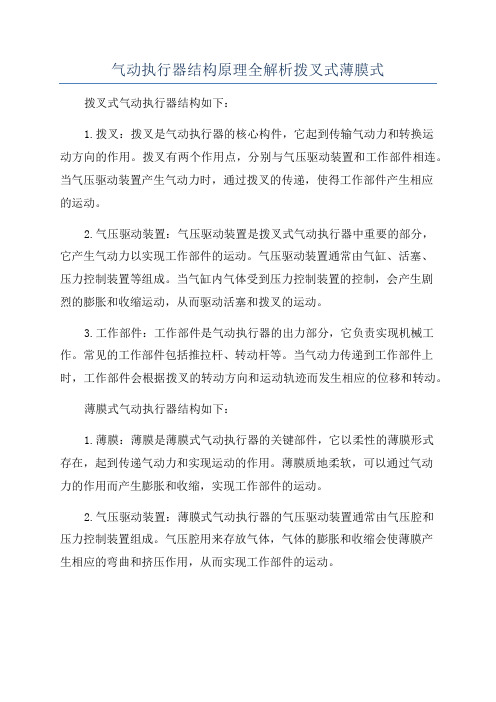
气动执行器结构原理全解析拨叉式薄膜式拨叉式气动执行器结构如下:1.拨叉:拨叉是气动执行器的核心构件,它起到传输气动力和转换运动方向的作用。
拨叉有两个作用点,分别与气压驱动装置和工作部件相连。
当气压驱动装置产生气动力时,通过拨叉的传递,使得工作部件产生相应的运动。
2.气压驱动装置:气压驱动装置是拨叉式气动执行器中重要的部分,它产生气动力以实现工作部件的运动。
气压驱动装置通常由气缸、活塞、压力控制装置等组成。
当气缸内气体受到压力控制装置的控制,会产生剧烈的膨胀和收缩运动,从而驱动活塞和拨叉的运动。
3.工作部件:工作部件是气动执行器的出力部分,它负责实现机械工作。
常见的工作部件包括推拉杆、转动杆等。
当气动力传递到工作部件上时,工作部件会根据拨叉的转动方向和运动轨迹而发生相应的位移和转动。
薄膜式气动执行器结构如下:1.薄膜:薄膜是薄膜式气动执行器的关键部件,它以柔性的薄膜形式存在,起到传递气动力和实现运动的作用。
薄膜质地柔软,可以通过气动力的作用而产生膨胀和收缩,实现工作部件的运动。
2.气压驱动装置:薄膜式气动执行器的气压驱动装置通常由气压腔和压力控制装置组成。
气压腔用来存放气体,气体的膨胀和收缩会使薄膜产生相应的弯曲和挤压作用,从而实现工作部件的运动。
3.工作部件:薄膜式气动执行器中的工作部件通常与薄膜直接相连,通过薄膜的弯曲和挤压来实现位移和转动。
工作部件的形状和结构根据具体应用需求而设计,可以是推拉式、旋转式等。
总的来说,无论是拨叉式还是薄膜式气动执行器,其结构都是通过气压驱动装置产生气动力,再通过核心构件(拨叉或薄膜)传递气动力,最终使工作部件实现机械工作。
这种结构设计简单,体积小巧,适用于各种工业领域的自动化设备和机械装置。
气动执行器的产品说明书

S E R I E S P L S O L E N O I D V A L V E SDirect acting solenoid valves Series PL2/2-way - Normally Open (NO)3/2-way - Normally Closed (NC) and Normally Open (NO) 3/2-way - Universal (UNI)Series PL solenoid valves are available in the normally closed, normally open and universal versions. They can be mounted on single sub-bases or manifolds.Please note that all Series PL solenoid valves are supplied with direct current (DC). To operate in alternating current (AC), it is necessary to use the connector with bridge rectifier Mod. 125-900.»Application sectors: - Industrial Automation - Life Science - Transportation »Mounting on a single base (M5 connections) or on manifold (M5 or fittings Ø3 and Ø4)GENERAL DATATECHNICAL FEATURES Function OperationPneumatic connections Orifice diameterFlow coefficient kv (l/min) Operating pressure Operating temperature MediaResponse time Manual override Installation2/2 NO - 3/2 NC - 3/2 NO - 3/2 UNI direct acting poppet type on subbase 0.8 ... 1.6 mm 0.30 ... 0.62 0 ÷ 3.5 ... 10 bar0 ÷ 50 °C (FKM) / -50 ÷ 50 °C (low temperature NBR on demand)filtered air class [5:4:4] according to ISO 8573-1:2010 (max oil viscosity 32 cSt), inert gas ON <10 ms - OFF <15 msmono/bistable - PBT 3/2 versions onlyin any positionMATERIALS IN CONTACT WITH THE MEDIUM Body SealsInternal parts brass - PBT - PPSFKM - NBR - EPDM (on demand) brass - stainless steelELECTRICAL FEATURES VoltageVoltage tolerance Power consumption Duty cycleElectrical connection Protection class6 ... 110 V DC - other voltages on demand ±10% 1.2 ... 3 W ED 100%industry standard connector (9.4 mm) IP65 with connectorSpecial versions available on demandS E R I E S P L S O L E N O I D V A L V ES* 3/2 NO IN-LINE version: the position of the ports 1 - 2 - 3 is identical to 3/2 NC versionCODING EXAMPLES E R I E S P L S O L E N O I D V A L V E SSeries PL solenoid valve - 2/2-way NO - series PD interfaceSupplied with: 2x O-Rings2x M3x20 screws for mounting on metal or2x Ø3x23 screws for mounting on plastic(opt. P)* add - VOLTAGE - FIXING(see CODING EXAMPLE)Series PL solenoid valve - 3/2-way NCSupplied with: 1x interface seal2x M3x20 screws for mounting on metal or2x Ø3x23 screws for mounting on plastic (opt. P)Also available ST models forT amb. -50 ÷ 50 °C with NBR seals.* add - VOLTAGE - FIXING(see CODING EXAMPLE)S E R I E S P L S O L E N O I D V A L V E S2x M3x20 screws for mounting on metal or2x Ø3x23 screws for mounting on plastic (opt. P)Also available ST models forT amb. -50 ÷ 50 °C with NBR seals.* add - VOLTAGE - FIXING(see CODING EXAMPLE)Series PL solenoid valve - 3/2-way NO IN-LINESupplied with: 1x interface seal2x M3x20 screws for mounting on metal or2x Ø3x23 screws for mounting on plastic (opt. P)Also available ST models forT amb. -50 ÷ 50 °C with NBR seals.* add - VOLTAGE - FIXING(see CODING EXAMPLE)S E R I E S P L S O L E N O I D V A L V E S2x M3x20 screws for mounting on metal or2x Ø3x23 screws for mounting on plastic (opt. P)Also available models for T amb. -50 ÷ 50 °C with NBR sealsVacuum operation with max. pressurereduction* add - VOLTAGE - FIXING(see CODING EXAMPLE)S E R I E S P L S O L E N O I D V A L V ESSingle sub-base for 15mm size 2 way interfaceSingle sub-base suitable for 2-way solenoid valves Series PD and PL models PD000-2A..., PL000-9B... Use solenoid valves with fixing screws for metal (see codification page)Material: anodized aluminiumConnections: G1/8 threadsSingle sub-base for 3-way solenoid valve size 15 mmSingle sub-base suitable for Series P - PL - PN - W 3-way solenoid valveUse solenoid valves with screws for mounting on metal (see coding)Material: anodized aluminiumConnections: M5 threadsSingle manifold with rear outletsManifold suitable for Series P - PL - PN - W 3-way solenoid valveUse solenoid valves with screws for mounting on metal (see coding)Material: anodized aluminiumS E R I E S P L S O L E N O I D V A LV E SManifold - single side valve - frontal outletsManifold suitable for Series P - PL - PN - W 3-way solenoid valveUse solenoid valves with screws for mounting on metal (see coding)Can be fixed through DIN 46277/3 guide with the accessory PCF-E520.Material: anodized aluminiumManifold - double side valve - bottom outletsManifold suitable for Series P - PL - PN - W 3-way solenoid valveUse solenoid valves with screws for mounting on metal (see coding)Material: anodized aluminiumManifold - double side valve - frontal outletsManifold suitable for Series P - PL - PN - W 3-way solenoid valveUse solenoid valves with screws for mounting on metal (see coding)Can be fixed through DIN 46277/3 guide with the accessory PCF-E520.Material: anodized aluminiumS E R I E S P L S O L E N O I D V A L V ESPosition valve capSupplied with:1x position valve cap 1x interface seal2x screwsConnector Mod. 125-... - industrial std. 9.4 mmConnector Mod. 125-... - industrial std. 9.4 mm - 90° cableThe internal rectifier circuit of the connectorMod. 125-900 allows to use solenoid valves with different AC voltage, even if the voltage indicated onthe solenoid valve is DC.S E R I E S P L S O L E N O I D V A L V E SConnector Mod. 125-... - industrial std. 9.4 mm - in-line cablewithout electronicsConn. Mod. 125-... - ind. std. 9.4 mm - in-line cable+rectifierwith voltage rectifierAC/DC。
Bray AU系列电动执行器使用说明书

clude two auxiliaryswitches, torque switches, a position indicator and a heater. Modulating units provide position feed-back as standard.AU series actuators mount directly to Bray butterfly valves and ball valves without the need for adapter bracket. Thermal overload protection is provided by means of PTC thermistors connected directly to the motor windings.AU Series - Specifications & Model SelectionModel NumberF e a t u r eT o r q u eO n /O ffM o d u l a t i n gH e a t e rA u x i l i a r y S w i t c h e s••••••••••••••••••AU-213021,300AU-2130SV 21,300AU-406840,680AU-4068SV 40,680AU-708070,800AU-7080SV70,800Technical SpecificationsOn/Off, Floating and Modulating 120 Vac, 60 Hz, +/- 10%, Single-Phase, Reversible, Permanent Split Capacitor Induction Motor Power Supply Full Load Locked Rotor14 APower Terminals 8 to 10 AWG (6 to 10 mm2)Controls Contacts14 AWG (2.5 mm2)24 V internal (12.5 W)Current DrawControl Module Voltage On/Off, Floating ModulatingModulating 24 VDC – 100 mA 115 VAC – 30 mA Output Aux.Voltage On/Off, Floating Modulating On/Off, Floating Declutchable Override Handwheel ModulatingMotor Protection 1 Ph-1 thermal switch 284°F (140°C) Class F insulation, tropicalized windingFeedback SignalControl Input Signal 4 to 20 mA 4 to 20 mAOutput Signals Terminal Strip Fault, End pos. CLOSED End pos. OPEN, Selector sw. REMOTE, Torque fault CLOSE, Torque fault OPEN Output Contacts 6 Output contacts: 6 NO/NC without common 5AEnclosure Heater NEMA types 6P (IP68) Corrosion Protection: KSWarranty3 Years limited from time of shipment.Manual Operation To close the valve, turn handwheel clockwise.Drive shaft (valve) turns clockwise in close direction.Conduit Entries Plug/socket 100 mm, 2 × 3/4” NPT; 1 × 1-1/4” NPT Dimensions See Page 4WeightAU-2130AU-4068AU-7080165 lbs. (75 kg)195 lbs. (88 kg)AU-2130AU-4068 & AU-7080 5.9 A 6.4 A278 lbs. (127 kg)Angle of Rotation 92° maximumOperating Time 60 Seconds Life Cycle 15,000 Full Stroke Cycles; 2,500,000 Repositions at Rated Running Torque Ambient TemperatureFail Position -13°F to 158°F (-25°C to 70°C)Duty Cycle Disclaimer - The performance specifications are nominal and conform to acceptable industry standards. For application at conditions beyond these specifications, consult the local Bray office. Bray, Inc. shall not be liable for damages resulting from misapplication or misuse of its products.AU-xxxx On/Off or Floating Control Type AU-xxxxSVModulating24 VDC 110 – 120 VAC 120 V internal (12.5 W)S4 – 25% Intermittent dutyOn/Off, Floating ModulatingS2 -15 min continuous, max. six starts/minute Default Setting Loss of supply power - Fail-in-placeCertifications CEAU Series - Model SelectionAU Series - WiringFIELD WIRING ACTUATORBCD-WD-A048NOTES:1. POWER INPUT FROM FIELD CONTROL PANEL TO ACTUATOR2. 120VAC COMMAND SIGNAL INPUT FROM FIELD CONTROL PANEL TO ACTUATOR (LIVE AND NEUTRAL BOTH REQUIRED FOR OPERATION)3. OPTIONAL: POWER OUTPUT FROM ACTUATOR TO BE USED BY FIELD CONTROL PANEL CONTACTS FOR ACTUATOR INPUTS4. OPTIONAL: 120VAC COMMAND SIGNAL INPUT FROM FIELD CONTROL PANEL TO ACTUATOR (LIVE AND NEUTRAL BOTH REQUIRED FOR OPERATION). FUNCTIONAL PURPOSE IS DETERMINED BY PROGRAMMING SELECTION5. OPTIONAL: DIGITAL OUTPUT FROM ACTUATOR, VOLTAGE FREE CONTACT. RATING: 250V 5AMP6. OPTIONAL: ANALOG OUTPUT FROM ACTUATOR TO BE USED BY FIELD PLC FROM MONITORING. 4-20mA @ 500 OHM MAXLEGEND:TERMINAL SYMBOLS FIELD WIRING FCTORY WIRING GROUNDCALIBRATION SEQUENCE:ACTUATOR THAT WAS FACTORY MOUNTED TO VALVE WAS CALIBRATED BY THE FACTORY IN ACCORDANCE WITH THE APPLICABLE AUMA OPERATION MANUAL.ON/OFF WIRINGAU Series - WiringFIELD WIRING ACTUATORBCD-WD-A049NOTES:1. POWER INPUT FROM FIELD CONTROL PANEL TO ACTUATOR2. 0/4-20mA COMMAND SIGNAL INPUT FROM FIELD CONTROL PANEL TO ACTUATOR3. OPTIONAL: POWER OUTPUT FROM ACTUATOR TO BE USED BY FIELD CONTROL PANEL CONTACTS FOR ACTUATOR INPUTS4. OPTIONAL: 120VAC COMMAND SIGNAL INPUT FROM FIELD CONTROL PANEL TO ACTUATOR (LIVE AND NEUTRAL BOTH REQUIRED FOR OPERATION)5. OPTIONAL: 120VAC COMMAND SIGNAL INPUT FROM FIELD CONTROL PANEL TO ACTUATOR (LIVE AND NEUTRAL BOTH REQUIRED FOR OPERATION). FUNCTIONAL PURPOSE IS DETERMINED BY PROGRAMMING SELECTION6. OPTIONAL: DIGITAL OUTPUT FROM ACTUATOR, VOLTAGE FREE CONTACT. RATING: 250V 5AMP7. OPTIONAL: ANALOG OUTPUT FROM ACTUATOR TO BE USED BY FIELD PLC FROM MONITORING. 4-20mA @ 500 OHM MAXLEGEND:TERMINAL SYMBOLS FIELD WIRING FCTORY WIRING GROUNDCALIBRATION SEQUENCE:ACTUATOR THAT WAS FACTORY MOUNTED TO VALVE WAS CALIBRATED BY THE FACTORY IN ACCORDANCE WITH THE APPLICABLE AUMA OPERATION MANUAL.MODULATING WIRINGAU Series - Dimensions AU-2130AU-4068AU-7080XXX10.4" [265] 6.8" [173]11.8" [300]5.9" [150]6.8" [173]4.9" [125]5.6" [143]1.6" [40]3.0" [75]5.8" [147]12.3" [313]8.9" [225]13.5" [342]11.8" [300]32.9" [836]ø 6.3" [160]10.6" [270]6.5" [166]XXX7.2" [182] 6.8" [173]8.3" [210]4.1" [105]5.8" [148]3.9" [100]6.0" [153]2.0" [50]3.0" [75]5.6" [143]12.7" [323]8.9" [225]10.6" [270]11.8" [300]29.9" [759]ø 7.9" [200]10.6" [270]5.7" [146]6.3" [160]9.8" [250]13.0" [330]6.3" [160]6.5" [165]8.6" [218]11.8" [300]16.5" [418]39.7" [1008]3.0" [75]6.1" [155]12.3" [312](2) 3/4"Conduit Entries(1) 1 1/4"5.6" [143]21.8" [553]11.7" [298]XXX。
美国爱诺执行器

美国爱诺气动执行器USA ALLIED SERIES PNEUMATIC ACTUATORS123456789Versa View Continuous IndicatorStainless SteelFasteners Namur MountingNamur ManifoldISOMountingBi-Directional StrokeAdjustment 可视指示器不锈钢紧固件NAMUR标准安装孔NAMUR标准安装孔双位调节ISO标准安装孔在常温工作条件下使用丁腈橡胶,在高温或低温时采用氟橡胶或硅橡胶。
NBR rubber O-rings provide trouble-free operation at standard temperature ranges.For high and low temperature applications Viton or Silicone.The pinion is high-precision and integrative, made from nickelled-alloy steel, full conform to the lastest standards of ISO5211, DIN3337, NAMUR.The dimensions can be customized and the stainless steel is available.镀镍合金钢、高精密一体式输出轴同时符合N A M U R 、ISO5211、DIN3337标准。
可根据客户要求定制尺寸和不锈钢材料。
NAMUR 标准指示器便于安装位置开关、定位器等附件。
Position indicator with NAMUR is convenient for mounting accessories such as Limit Switch box,Positioner and so on.According to the different requirements, the extruded aluminum alloy ASTM6005 Body can be treated with hard anodized, powder polyester painted (different colours is available such as blue, orange, yellow etc.), PTFE or Nickel plated.ASTM6005压铸铝合金缸体可以采用硬质氧化、环氧树脂喷涂(根据要求喷涂兰色、橙色、黄色等)、PTFE涂层或镀镍满足不同要求。
柏勒夫气动执行器说明书

BELEF Pneumatic Actuators Incorporate latest mechanical technology, materials available through designing, developing, testing and engineering application, we have obtained a high grade product with the characteristics of reliability, high performance, long cycle life, large adjustment, highest levels of corrosion protection, wide selection of model with easy and economy.柏勒夫气动执行器柏勒夫气动执行器综合了国际最新材料技术、精密加工技术、工业美术设计技术。
经过设计、开发、测试、生产和工程运用,该系列执行器具有运行可靠、工作寿命长、可调范围大、防腐性能高、规格多、选型灵活、经济实惠等优点。
性能、结构和设计特点● 挤压铝质(ASTM6005)缸体,内表面细磨精加工,内部和外部均采用高级防腐技术,气缸摩擦系数小,使用寿命长,抗腐蚀性能强。
● 双活塞齿轮齿条式设计,结构紧凑、安装位置对称、改变输出轴转向方便,使用寿命长、动作迅速。
活塞齿条背面装有复合轴承及导向环,动作精确、摩擦系数小、使用寿命延长。
● 组合式预负荷镀层弹簧,工作寿命长。
● 高精度齿轮和齿条,啮合间隙小、精度高,输出功率大。
● 不锈钢紧固件,安全美观,抗腐蚀性强。
● 采用国际规范尺寸:输出轴槽、螺孔;顶部安装孔尺寸符合NAMUR 标准;气源接口尺寸符合NAMUR 标准;底部安装孔尺寸符合IS05211、DIN3337标准,方便安装电磁阀限位开关等附件。
Design & Constructin of BAILEFU Pneumatic Actuators气动执行器结构Construction of Pneumatic Actuator● Extruded aluminum ASTM6005 body with bath internal and external corrosion protection having honed cylinder surface for longer life and low coefficient of friction.● Dual piston rack and pinion design for compact construction, symmetric mounting position, high-cycle fife and fast operation, reverse rotation can be accomplished in the field by simply inverting the pistons. ● Multiple bearings and guides on racks and pistons, low friction, high cycle life an d prevent shaft blowout.● Modular preloaded spring cartridge design, with coatedspring for simple versatile range, greater safely and corrosion resistance, longer cycle life.● Fully machined teeth on piston and pinion for accurate low backlash rack and pinion engagement, maximum efficlency. Stalnless steel fasteners for long term corroslon resistance● Full conformance to the latest specifications: IS05211,DIN 3337 and Namur or product inter changeahility and easy mounting of solenoids, limit switches and other aocessodes.have obtained a high grade product with the characteristics of reliability, high performance, long cycle life, large adjustment, highest levels of corrosion protection, wide selection of model with easy and economy.执行器零件、材料一览表Actuators Parts and Material Tablehave obtained a high grade product with the characteristics of reliability, high performance, long cycle life, large adjustment, highest levels of corrosion protection, wide selection of model with easy and economy.工作原理和输出扭矩Operating Principle and Out Torquehave obtained a high grade product with the characteristics of reliability, high performance, long cycle life, large adjustment, highest levels of corrosion protection, wide selection of model with easy and economy.工作原理和输出扭矩Operating Principle and Out Torquehave obtained a high grade product with the characteristics of reliability, high performance, long cycle life, large adjustment, highest levels of corrosion protection, wide selection of model with easy and economy.工作原理和输出扭矩Operating Principle and Out Torque柏勒夫气动执行器柏勒夫气动执行器综合了国际最新材料技术、精密加工技术、工业美术设计技术。
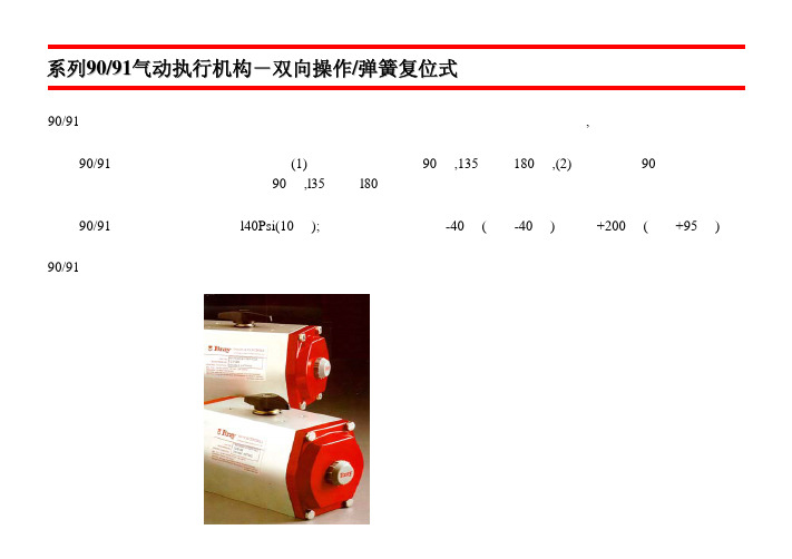
bray气动阀门S90-91中文说明书
D
8
10
13
13
22
22
22
12
16
E
74 110 130 137 176 196 240 296 338
F*
see dwg.
132
177
202
215
290
368
450
665
G
M5 M6
M8
M8
M8
M8 M12 M12 M16
(UNC) ×6
×8
×8
×10 ×10 ×10 ×14 ×14 ×19
H (UNC)
转动及供应的连接支架或套板。
BACK NEXT
系列90/91气动执行机构-双向操作/弹簧复位式
4 通与 3 通电磁阀 系列 63 用于气动执行机构“开关” 的电动操纵。系列 63 电磁阀 采用 NEMUR 标准可直接安 装在执行机构上。防水型为: (NEMA 4,4X)防水防爆型(NEMA 4,4X,7,9)。空气接 管尺寸:1/4”NPT:电线连接;1/2”NPT。 手动现场操纵杆位于电磁阀之上。系列 55 速度控制阀可 以独立地控制执行机构开关的速度。3 通电磁阀,请与博 雷或代理商咨询。 气动定位器 系列 64 在需求调节阀门工况下采用 气动定位器系列 64 可准确地 指示阀门角度介于 0-90 度。 标准控制信号是(0.2)至(1.0) 巴(3-15psi)。它可用于双作用 或单作用弹簧复位气动执行机构上。 亦可用于需要有逆或分区范围。直接安装在执行机构。
—
M8 ×10
M8 ×10
—
M10 M12
×4
×14
—
M16 M16 ×19 ×19
J
—
22
气动执行器工作原理

气动执行器工作原理 Last revised by LE LE in 2021GT气动执行器 Pneumatic Actuators主要特点及标准参数:基本设计:气动双活塞执行器、型号GT双作用式、型号GT-S单作用式(有弹簧返回)。
制造特点:超宽面齿条(活塞)小齿轮传动技术、活塞及齿轮和壳体接触面有低磨擦材料制成的滑动轴承衬套、导向。
单作用式有保险弹簧座。
采用标准:执行器与阀门连接:四个或八个螺栓孔符合标准DIN/ISO5211,轴装配孔符合标准DIN3337。
可供选择的装配轴孔有多种形状尺寸选择。
执行器与控制阀连接:GT/GT-S100~350符合标准NAMUR或VDI/VDE3845,GT/GT-S040~90通过转接板连接。
执行器与信号盒连接:符合VDI/VDE3845零件材料:壳体:铝合金表面阳极化处理。
端盖:铝合金表面喷塑处理。
活塞/齿条:铝合金。
密封O型圈:丁睛橡胶=NBR70。
轴承垫圈/导环:塑料。
工作环境温度:—20°C+90°C。
回转角度:双作用式=90°单作用式=90°、标准执行器旋转轴角度从两端可调节-5°+5°。
输出扭矩:3~10000Nm空气压力:2~8bar,最大10bar。
附件:电磁阀、电气定位器、限位开关、气源处理三联件(有减压器、过滤器、油雾器)手操机构。
工作原理:双作用式压缩空气从气口(B)进入气缸两活塞(C)之间中腔时,使两活塞分离向气缸两端方向移动,两端气腔的空气通过气口(A)排出,同时使两活塞(C)的齿条同步带动输出轴(D)(齿轮)逆时针方向旋转90度。
可以从两端调整微量角度,松动螺母(E)用内六角扳手拧动调节螺栓(F)调整所需角度 , 锁紧螺母(E)。
反之压缩空气则从气口(A)进入气缸两端气腔时,使两活塞向气缸中间方向移动,中间气腔的空气通过气口(B)排出,同时使两活塞(C)的齿条同步带动输出轴(D)(齿轮)顺时针方向旋转90度。
气动执行器结构原理全解析拨叉式薄膜式

气动执行器结构原理全解析-拨叉式-薄膜式.....————————————————————————————————作者: ————————————————————————————————日期:ﻩ气动执行器是什么?结构和工作原理全在这里!可能在刚接触阀门行业的人对执行器不是很了解,执行器分为气动、电动等多种方式,那么常见的气动执行器又是怎样的工作原理,本文将从多个方位解析各位行业人士的疑问。
(OMAL气动执行器——拨叉式结构)一、气动执行器概述气动执行器是用气压力驱动启闭或调节阀门的执行装置,又被称气动执行机构或气动装置,不过一般通俗的称之为气动头。
气动执行器的执行机构和调节机构是统一的整体,其执行机构有拨叉式、薄膜式、活塞式、拨叉式和齿轮齿条式。
活塞式行程长,适用于要求有较大推力的场合;而薄膜式行程较小,只能直接带动阀杆。
拨叉式气动执行器具有扭矩大、空间小、扭矩曲线更符合阀门的扭矩曲线等特点,但是不很美观;常用在大扭矩的阀门上。
齿轮齿条式气动执行机构有结构简单,动作平稳可靠,并且安全防爆等优点,在发电厂、化工,炼油等对安全要求较高的生产过程中有广泛的应用。
二、气动执行器的工作原理1.双作用气动执行器工作原理图当气源压力从气口(2)进入气缸两活塞之间中腔时,使两活塞分离向气缸两端方向移动,两端气腔的空气通过气口(4)排出,同时使两活塞齿条同步带动输出轴(齿轮)逆时针方向旋转。
反之气源压力从气口(4)进入气缸两端气腔时,使两活塞向气缸中间方向移动,中间气腔的空气通过气口(2)排出,同时使两活塞齿条同步带动输出轴(齿轮)顺时针方向旋转。
(如果把活塞相对反方向安装,输出轴即变为反向旋转)2.单作用气动执行器工作原理图当气源压力从气口(2)进入气缸两活塞之间中腔时,使两活塞分离向气缸两端方向移动,迫使两端的弹簧压缩,两端气腔的空气通过气口(4)排出,同时使两活塞齿条同步带动输出轴(齿轮)逆时针方向旋转。
在气源压力经过电磁阀换向后,气缸的两活塞在弹簧的弹力下向中间方向移动,中间气腔的空气从气口(2)排出,同时使两活塞齿条同步带动输出轴(齿轮)顺时针方向旋转。
关键石F89气动执行器SIL安全手册说明书
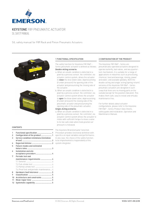
KEYSTONE F89 PNEUMATIC ACTUATOR SIL SAFETY MANUALSIL safety manual for F89 Rack and Pinion Pneumatic Actuators1 FUNCTIONAL SPECIFICATIONThe safety function for Keystone F89 R&P - Series pneumatic actuator is defined as follows:Double-Acting scenario:a. When an unsafe condition is detected in a plant by a process sensor, the controller, via actuator control system, drives the actuator to close the shut-down valve, depressurizing (if under pressure) the opening side of the actuator and pressurizing the closing side of the actuator.b. When an unsafe condition is detected in a plant by a process sensor, the controller, via actuator control system drives the actuator to open the blow-down valve, depressurizing (if under pressure) the closing side of the pneumatic actuator and pressurizing the opening side of the pneumatic actuator.Single-Acting scenario:a. When an unsafe condition is detected in a plant by a process sensor, the controller, via actuator control system drives the actuator to rotate with sufficient torque to move a valve to its fail-safe state when hold-position air pressure is released.The Keystone Brand Actuator SelectionProcedure provides functional definition with specifics on input variables and performance.In any case, the choice of the safety function to be implemented is responsibility of the system integrator.CONTENTS1 Functional specification ..........................12 Configuration of the product . (13)S ervice condition limitations (limitation of use) .....................................................24 Expected lifetime ....................................25 F ailure modes and estimatedfailure rates (36)I nstallation and site acceptance procedure .............................47 P eriodic test andmaintenance requirements ....................4 7.1 General ..................................................4 7.2 F ull-stroke test .....................................4 7.3 Partial-stroke test ................................4 7.4 Proof test and periodic maintenance ...48 Hardware fault tolerance .......................59 Classification ..........................................510 Architecture and constraints ..................511 Mean repair time ....................................512 Systematic capability ..............................5 2 CONFIGURATION OF THE PRODUCT The Keystone F89 R&P - Series arepneumatically-operated actuators designed to operate butterfly, ball valves, and any quarter- turn mechanism. It is suitable for a range of applications in industries such as processing, chemical, food and beverage, mining, power and water, and available globally. Both the double-acting and single-acting (spring-return)versions of the Keystone F89 R&P - Series pneumatic actuators are designed in such a way that there are no moving parts on the outside (except for the position indicator). This makes them safe, easy to install and virtually maintenance free.For further details about actuatorconfigurations, please refer to the Keystone F89 R&P - Series Product Data Sheets, safety guide and Installation, Operation and Maintenance Manual.3 SERVICE CONDITION LIMITATIONS (LIMITATION OF USE)The operating capabilities are listed below:• Operating medium: Compressed air (dry and lubricated)• Maximum Operating Pressure:- Pneumatic service.- 8.3 bar (120 psi) max. dynamic- 10 bar (140 psi) max. static• Temperature range: Temperature extremes require different solutions to maintain actuator operational integrity and reliability. For each Keystone F89 - Series actuatoris available in three different temperature executions.- S tandard temperature version:-20 °C to 80 °C (-4 °F to 176 °F)- L ow temperature version:-52 °C to 65 °C (-62 °F to 149 °F)- H igh temperature version:-15 °C to 150 °C (-5 °F to 302 °F)• Torque output range:- D ouble-acting F89 R&P - Series actuators, requiring pressure to rotate in eitherdirection, are available with a torque range between 11 Nm (97 lbf.in) and 4173 Nm(36,955 lbf.in)- S pring-return F89 - Series actuators,require pressure in only one direction oftravel and are suitable for air-fail closeand air-fail to open applications withoutmodification. These models are availablewith a spring end torque between 6 Nm(51 lbf.in) and 1663 Nm (14,729 lbf.in)• Travel adjustment:- O ptimized product flow with standardmounted travel stops for valve positionadjustment in open and close position(+/- 5° at each end of travel)- 0-100% travel stop available on request • Safety function:- P re-compressed spring cartridge design for ease of assembly and disassembly- A nti-blowout drive pinion- N o stopper bolt extends beyond the body - I ntegrated connections- F ail-safe actuator, spring-close andspring-open- A djustable stopper (+/- 5°)Use the 4 (B)-Port for safety related systems on Double-acting actuators:Assembly Code: CW= Safety function is counterclockwise rotationAssembly Code: CC= Safety function is clockwise rotation2 (A)4 (B)4 (B)2 (A)2 (A) 2 (A)4 (B)4 (B)4 EXPECTED LIFETIMEActuator lifetime (for which failure ratesindicated in section 5 are ensured) stronglydepends on operating conditions.For normal service conditions, KeystoneF89 R&P - Series actuators can be in goodconditions with max 500,000 cycles or 15 yearswith regular inspection whichever comes first.Normal working life is the number of cycles asdefined in Table 1 of EN 15714-3.5 FAILURE MODES AND ESTIMATED FAILURE RATESWarranty data and details from the extensive testing that is performed in-house by themanufactures were used to perform the calculations. Failure data for 2019-2022 were provided by the company and used in this study.• Determination of SIL parametersA detailed Failure Mode, Effects, and Diagnostics Analysis (FMEDA) integrated with fieldfeedback according to IEC 61508-2 par 7.4.4.3.3. has been carried out in order to detail all failure rates and failure modes of Keystone actuator F89 R&P series.Based on the FMEDA study carried out for actuator series, the individual failure rates and PFD were calculated.According to D.2.2 of IEC 61508-2:2010 Annex D, the estimated failure rates of the failure modes that result in a failure of the safety function are quoted in the following table:TABLE 1 - DETERMINATION OF SIL PARAMETERSVariants Failure rate (number offailures/hrs.)FD avgDC ʎDD ʎDU 1oo11oo2%Double Acting (DA)0.00E+00 1.24E-08 5.46E-05 5.46E-060Spring return (SR)0.00E+00 2.36E-081.04E-04 1.04E-050NOTES1. The architecture constraint can be evaluated per route 2H (IEC 61508-2 par.7.4.4).2. No internal diagnostic is included in the device3. The above failure rates are guaranteed:a) For service conditions listed in par. 3b) For the expected lifetime declared in par. 4c) Considering the periodic test and maintenance included in par. 74. The failure rates are determined performing a FMEDA based on failure rates of components taken from fieldfeedback using the Bayesian statistic approach mentioned in IEC 61508-2 par.7.4.4.3.3. The system for reporting failures is based on field feedback end users, with:• Identification of claim/failure• Root cause analysis to identify cause and responsibility of the failure • Identification of possible effect of failure on the Safety function• Classification of the failure considering the failure categories of IEC 61508-2 (Safe, dangerous, no effect).5. Emerson is using data from China manufacturing site, where are recorded for each actuator withNonconformance Report and retrofit activities done, with failures classification (Safe, dangerous and no effect) related to each specific application and actuator safety function.6. Customer service, quality and technical department are responsible for the procedure, according to therespective role.6 INSTALLATION AND SITE ACCEPTANCE PROCEDUREAny necessary installation and site acceptance procedures are discussed in the Keystone F89 R&P - Series actuators Installation, Operation and Maintenance manual. The Installation, Operation and Maintenance manual defines exercising of the actuator after installation and defines testing after maintenance.7 PERIODIC TEST AND MAINTENANCE REQUIREMENTS7.1 GeneralPlease consider that the information in this paragraph are relevant only in regards of Reliability Tests; please refer to Document, Installation, Operation and Maintenance manual for detailed information about product maintenance, handling and storage.Diagnostic tests may be made to increase the system reliability (Full-stroke or Partial-stroke test).“On-site” tests depend on project/plant facilities/requirements; however, a functional test must be executed on site, prior actuator operation.7.2 Full-Stroke testThe “Full-Stroke Test” (“On-line”) must be performed to satisfy the PFD AVG (average probability of failure on demand) value.The full-test frequencies will be defined by the final integrator in relation to the defined SIL level to achieve.• Procedure:- O perate the actuator/valve assembly forNo. 2 open/close complete cycles withcomplete closing of the valve.- V erify the correct performing of open – close maneuver (for example, check locally, orautomatically via logic solver, the correctmovement of the actuator/valve). Considering the application of the above described Full-Stroke Test Procedure, the “Test Coverage” can be considered 99%.7.3 Partial-Stroke testThe “Partial-Stroke Test” (“On-line”) can be performed to improve the PFD AVG value.A typical partial-stroke value is 15% of the stroke.The “Partial-Stroke Test” (“On-line”) can be performed to satisfy PFD AVG (average probability of failure on demand) value.• Recommended Test Interval = 1 to 3 months.• Procedure:- O perate the actuator/valve assembly forNo. 1 open/close cycles 15/20% ofthe stroke.- V erify the correct performing of partial-stroke operation (for example, check locally, or automatically via logic solver, or via thePST system the correct movement of theactuator/valve till 15/20% of the stroke).The above parameters to check will depend from the partial-stroke test system available. Considering the application of the above described Partial-Stroke Test procedure, the “Diagnostic Coverage” is >90%.7.4 Proof test and periodic maintenanceWe advise to perform the following checks upon each proof test interval complying with the rules and regulations of the country of final installation:• Visually check the entire actuator as well as the control system (where foreseen).• Ensure there are no leaks on the actuator parts under pressure.• Check pneumatic connections for leaks. Tighten tube fittings as required.• Check if manual override (where foreseen)is regular.• Check if pneumatic filter cartridge (where foreseen) is sound and filter bowl (where foreseen) has been cleaned properly.• Check the setting of the relief valves (where foreseen).• Verify that the power fluid supply pressure value is within the required range.• Remove built-up dust and dirt from all actuator surfaces.• Inspect actuator paint work for damagesto ensure continued corrosion protection. Touch-up as required in accordance with the applicable paint specification.• Operate the actuator/valve assembly for No. 2 open/close complete cycles with complete closing of the valve.• Verify the correct performing of open – close operations (for example, check locally, or automatically via logic solver, the correct movement of the actuator).The Installation, Operation and Maintenance manual defines under normal operating conditions and when basic pneumatic system maintenance procedures are applied, the F89 actuator will require minimum maintenance for hundred thousand of cycle. If O-ring wear out and air leakage occurs, a soft goods kit can be ordered. This addresses components that may have age-related degradation. When the maintenance interval has elapsed, a complete overhaul of the actuator is required.VCOSI-16511-EN © 2022 Emerson Electric Co. All rights reserved 08/22. Keystone is a mark owned by one of the companies in the Emerson Automation Solutions business unit of Emerson Electric Co. The Emerson logo is a trademark and service mark of Emerson Electric Co. All other marks are the property of their prospective owners.The contents of this publication are presented for informational purposes only, and while every effort has been made to ensure their accuracy, they are not to be construed as warranties or guarantees, express or implied, regarding the products or services described herein or their use or applicability. All sales are governed by our terms and conditions, which are available upon request. We reserve the right to modify or improve the designs or specifications of such products at any time without notice.Emerson Electric Co. does not assume responsibility for the selection, use or maintenance of any product. Responsibility for proper selection, use and maintenance of any Emerson Electric Co. product remains solely with the /FinalControl8 HARDWARE FAULT TOLERANCEThe hardware fault tolerance of the device is 0.The requirements of minimum hardware fault tolerance (HFT) according to Tab.6 ofIEC 61511-1 must be observed but, as long as an assessment report has been performed fully in compliance with IEC 61508 part 1 to 7, alternative fault tolerance requirements have to be considered applicable according to Table 2 of IEC 61508-2 as per par. 11.4.5 of IEC 61511-1.9 CLASSIFICATIONThe equipment is classified Type A according to IEC 61508-2.10 ARCHITECTURE AND CONSTRAINTS For the evaluation of conformity to the requirement of Hardware Safety integrity, architectural constraints of the standard IEC 61508, Route 2H is used.The application of route 2h (proven in use approach) is evaluated according to paragraph 7.4.10.1 / 7.4.10.7 of IEC 61508-2. Evidence was identified for each specific point.As the actuator is classified as Type A, no requirements for SFF are given for Route 2H.The actuator can be used in single channel configuration up to SIL 3, considering external diagnostic test.11 MEAN REPAIR TIMEMean Repair Time (MRT) of the actuator is assumed to be 24 hours.N O TICEThe MRT is estimated considering availability of skilled personnel for maintenance, spare parts and adequate tools and materials on site (that is, it encompasses the effective time to repair and the time before the component is put back into operation).Procedures to repair or replace theKeystone F89 R&P - Series actuators areprovided in the respective Installation, Operation and Maintenance manual. Please refer to the Installation, Operation and Maintenance manual for any tools required for repair and replacement and required competency of technicians.Maintenance and subsequent test procedures are also covered in the Installation, Operation and Maintenance manual. Any failures, identified by the end-user during maintenance, repair or proof testing, that potentially impact the functionalsafety of the Keystone F89 R&P - Series actuators should be reported back to Emerson Customer Service Coordinator.12 SYSTEMATIC CAPABILITYThe systematic capability of the device is 3.This systematic capability is guaranteed only if the user:• Use the device according to the instructions for use and to the present manual.• Use the device in the appropriate environment (limitation of use).。
拨叉式气动执行器结构原理 气动执行器工作原理
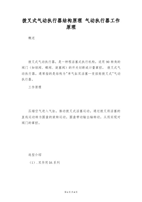
拨叉式气动执行器结构原理气动执行器工作原理概述拨叉式气动执行器,是一种程活塞式执行机构,适用90转角的阀门(如球阀、蝶阀、旋塞阀)的开关切断或计量掌控。
拨叉式气动执行器,通常指的是结构为"单气缸双活塞—变扭矩拨叉式"气动执行器。
工作原理压缩空气进入气缸,推动拨叉式活塞运动,通过拨叉将活塞的直线运动转为圆盘的旋转运动,圆盘带动输出轴转动,从而实现对阀门的掌控。
选型介绍(1).双作用DA系列使用双作用气动执行器,先确定阀门的扭矩,水蒸汽或非润滑的介质加添30%安全值;非润滑的干气介质加添50%安全值;非润滑气体输送的颗粒粉料介质加添100%安全值;对于清洁、无摩擦的润滑介质加添20%安全值,然后依据气源工作压力,查找双作用气动执行器扭矩表,可得到精准的DA系列气动执行器型号。
(2).单作用(弹簧复位)SA系列使用单作用式执行器,先确定阀门的扭矩,水蒸汽或非润滑的介质加添25%安全值;非润滑的干气介质加添60%安全值;非润滑气体输送的颗粒粉料介质加添100%安全值;对于清洁、无摩擦的润滑介质加添20%安全值,然后查找单作用气动执行器扭矩表,先查弹簧复位尽头,再查气源工作压力尽头,气源压力扭矩应当大于弹簧复位扭矩,可得到精准的SA系列气动执行器型号。
单作用SA系列输出扭矩表中,弹簧复位"0"扭矩即为关闭阀门的扭矩,弹簧复位"90"扭矩即为打开阀门的扭矩。
相对应的气源压力"0"的扭矩即为关闭阀门的扭矩,气源压力"90"扭矩即为打开阀门的扭矩。
气动执行器的功能介绍标准型气动执行器致力于提高节能和安全性,有快速响应、体积小、长寿命等特点,并以拨叉式结构设计确保阀门启闭时的强力扭矩和低摩擦低耗损,载荷本领高并对于负载骤加有良好的阻抗本领,特别适用于空间有限、有大量使用需要场所的应用。
有双作用式和单作用式(弹簧复位)。
博力谋角行程电动执行器调试记录

博力谋角行程电动执行器调试记录博力谋是一家专业从事电动执行器研发和生产的公司。
电动执行器是一种能够根据控制信号实现开关或调节阀门、阀门、阀门装置的自动化执行器。
在实际应用中,电动执行器的调试是非常重要的一步,下面将以博力谋角行程电动执行器调试记录为题,详细描述电动执行器的调试过程和注意事项。
一、调试前的准备工作在进行电动执行器的调试之前,首先需要进行一些准备工作。
首先,需要对电动执行器的相关参数进行了解,包括角行程范围、工作电压、额定负载以及控制信号等。
其次,需要了解电动执行器的工作原理和结构特点,以便更好地进行调试。
最后,需要准备相应的调试工具和设备,如电动执行器控制器、电动执行器连接线等。
二、调试步骤1. 连接电源和控制信号将电动执行器的电源线和控制信号线连接到相应的电源和控制设备上。
在连接过程中,要确保电源和控制信号的极性正确,避免短路或反相等问题。
2. 开始调试打开控制设备的电源,启动电动执行器。
观察电动执行器的运行情况,检查角行程是否正常,是否能够根据控制信号实现开关或调节阀门的功能。
3. 调整行程范围如果发现电动执行器的角行程范围不符合要求,需要进行相应的调整。
一般情况下,电动执行器上会有相应的调节螺丝或刻度盘,可以通过调整这些部件来改变角行程的范围。
调整时要小心操作,避免过度调整或调整不到位。
4. 调整速度和力矩除了行程范围外,电动执行器的速度和力矩也是需要调试的重要参数。
通过调整控制设备上的相应参数,可以改变电动执行器的运行速度和输出力矩。
调试时要根据实际需求进行调整,确保电动执行器的运行速度和力矩能够满足实际应用的要求。
5. 测试反馈信号电动执行器在工作过程中,通常会输出一些反馈信号,如开关信号、行程信号等。
在调试过程中,需要测试这些反馈信号是否正常。
可以通过连接示波器或多用表等测试设备,对反馈信号进行检测和分析,确保其准确可靠。
6. 调试记录和整理在进行电动执行器的调试过程中,应当及时记录调试参数、操作步骤和调试结果等信息。
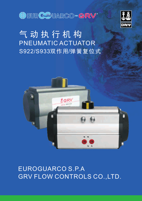
GRV-气动执行器S922_933
584 322 797 535 1010 748 1223 960 742 480
285 523 418 789 684
380 275
209 468 342 734 608 1000 874
456 330
358 190 624 456 890 722 1156 988 1422 1254
608 440
23.0 15.8
6 20.1 11.5 28.0 19.3 43.7 35.1 59.4 50.7
27.6 19.0
8
21.7 10.1 37.4 25.8 53.1 41.5 68.8 57.2 84.5 72.9
36.8 25.3
10
31.0 16.6 46.7 32.3 62.4 48.0 78.1 63.7 93.8 79.3 46.0 31.6
单作用执行器的选型
在 正 常 工 作 条 件 下 , 单 作 用 执 行 器 考 虑 的 安 全 系 数 为3 0 % - 5 0 % 例如: 阀门需要力矩 =79N.m 安全力矩=79(1+30%)=103N.m气 源压力=5Bar 对 照 单 作 用 执 行 器 输 出 力 矩 表 , 我 们 可 以 查 到S 9 3 3 - 4 3 5 - 6输 出 力 矩 为 空气行程 0°=325N.m 空气行程 90°=273N.m 弹簧行程 90°=155N.m 弹簧行程 0°=103N.m 所有输出力矩均大于我们需求。
23.2 16.9
10
19.0 11.1 28.8 21.2 39.0 31.2 49.1 41.2 59.1 51.2 29.0 21.1
12
24.9 15.4 34.9 25.4 44.9 35.4 54.9 45.4 34.7 25.3
- 1、下载文档前请自行甄别文档内容的完整性,平台不提供额外的编辑、内容补充、找答案等附加服务。
- 2、"仅部分预览"的文档,不可在线预览部分如存在完整性等问题,可反馈申请退款(可完整预览的文档不适用该条件!)。
- 3、如文档侵犯您的权益,请联系客服反馈,我们会尽快为您处理(人工客服工作时间:9:00-18:30)。
结合了独特的风格,简洁的设计和实用性,美国博雷控制公司提供新的 S92/S93 系列的高性能,优质的气动执行机 构来适应当今市场的需求。 先进的技术,精密的加工制造,经济实用,节省空间。而且,模块设计,可直接安装其他博雷配件,增加其效率和 经济性。 系列 92/93 气动执行机构是齿条齿轮,双活塞设计。分两种型号:双作用-90 度、135 度和 180 旋转度;弹簧复位-90 度旋转。两者能理想的驱动球阀、蝶阀或旋塞阀,并应用于 90 度,135 度和 180 度旋转。手轮和输出轴产生的偏 心负荷正好由低摩擦系数醇缩醛轴承来承受。 系列 92/93 的最高工作压力可达 140psi(10Bar);温度范围从-40ºF (-40º C)至 200º F(95º C)。如需更高或更低的工作 温度,请问博雷厂家或经销商咨询。
数量
说 明
1
外壳
2
活塞
1
齿轮
2
端盖
最大 12 弹簧组合
1
上轴承
1
下轴承
1
保持环
1
尼龙垫圈
2 醇缩醛轴承垫片
2
醇缩醛导环
2
行程限制螺母
2 可调行程限制螺丝
2 行程限制 O形环
1
醇缩醛衬套
1
行程限位
8
六角螺丝
8
垫圈
2
活塞 O形环
2
端盖 O形环
1
上轴 O形环
1
下轴 O形环
1
开度指示
1
开度指示器
标准材料 外壳:挤压铝,经氧化处理
注:不可超过以上最大调节范围
上图所示为系列 93 弹簧复位的组件 *系列 92 双作用不包 含弹簧组件
关。其他选择有四个微型开关、二个接近开关、二个气动 他行程范围调节。输入信号可
开关或信号电位表。外壳有防水型(NEMA 4,4X)和防水 为 0-20mADC 或 4-20mADC,数字式控制,先进的微处
防爆型(NEMA 4,4X,7,9)。 理器控制的数字式和智能式电气动定位器。
S52 阀门状况监视器
S63 3 通和 4 通电磁阀 用于 气动执行机构“开关”的电动 操纵。系列 63 采用 NAMUR 标 准可直接安装于执行机构,通 过转换板,可将 3 通(2 位 3 通) 转至 4 通(2 位 5 通)。防水型为 NEMA4,4X,防爆型为
直接安装在阀门上 博雷的执行 机构符合 ISO521l 尺寸标准,能 直接安装在博雷阀门上。直接安 装可避免不必要的连接支架或套 板。方便于现场安装及减少安装 偏心误差。博雷执行机构能安装 在其他需要 90 或 180 度转动的阀 门上并提供连接支架或套板。
逆时针:在整个过程中气体推动两活塞分开 顺时针:在整个过程中气体推动两活塞合拢
NAMUR 标准 输出轴顶端
4.06 3.98
210、255 型执行器 阀杆连接孔详解
BACK
系列92/93气动执行机构-双作用/弹簧复位
组件 项目
1 2 3 4 5* 6 7 8 9 10 11 12 13 14 15 16 17 18 19 20 21 22 23 24
能直接安装在执行器上部。其 200mA。
特点包括“手指控制”凸轮、 S67 电气动定位器
“防掉”式外壳螺丝、现场开 此系列的调节型设计使附件自
度指示器和两个电线入口。内 由组合。应用于双作用或单作
部行程开关预先连接“接线终端”,在 125 或 250 伏特, 用执行机构,可独立提供直接
额定电流是 15A。标准开关是两个单刀双掷(SPDT)微型开 送返操作模式,以及零位和其
重量以磅为单位,系列93每活塞内置6件弹簧
活塞排气量/容量(cm3) 尺 寸 48 63 83 92 118 127 160 210 255
反时针方向 93 157 407 571 1210 1586 3075 5904 12300 顺时针方向 79 220 535 753 1566 2145 4257 7380 14760
介 绍
选择附件
参 数
扭 矩
规 格
系列92/93气动执行机构-双作用/弹簧复位
双作用和弹簧复位执行机构都可以应用于开关或调节控制。系列 92/93 也可由水或油来驱动。 系列 92/93 是全密封,模块式设计,维修少,操作安全,组装和拆卸容易。 内部气路(A) 经济并且无须连接管线,避免了因外露而受损。 醇缩醛轴垫片(B)和活塞导环(C) 都有很低的摩擦阻力,能吸收活塞侧向推力。气缸内壁经过珩磨,减少整体摩擦 阻力。系列 92/93 具有较长使用期限,是市场上最好的气动执行机构。 输出轴承(D) 由低摩擦阻力的醇缩醛构成,位于小齿轮的顶部和底部。 输出轴承和小齿轮(E) 是一体式,由镀锌合金钢制成,防腐。 开度指示(F) 清晰的显示“开”或“关”的位置。易于拆除, 以便人工操作。 外壳(G) 是挤压铝,经氧化处理防腐涂层。 端盖(H) 是铸压铝,防腐垫塑性涂层,能耐弱酸, 弱碱,石油溶剂,净化剂,无机盐,酒精,烯烃, 油脂等。 行程限制(I) 螺丝可调节限定气动执行机构至指定 角度。 活塞(J) 由铸压铝制成。 两个供气孔(K) 尺寸:1/8”NPT 适用于 048 执行机构。 另有 1/4”NPT。防爆接口为标准配置。 所有系列 92/93 执行机构在出厂前轴承和导环都经过 油脂润滑。所有密封,包括活塞密封(L),都采用永久润滑的丁腈橡胶 O 形环。
30
50
64
D
10
10
13
13
22
22
22
12
16
E
99 115 138 147 185 205 238 291 339
F G (UNC) H (UNC)
102 142 188 218 302 313 10-32 1/4-20 1/4-20 1/4-20 5/16-18 5/16-18 x .23 x .32 x .32 x .32 x .46 x .46 1/4-20 5/16-18 5/16-18 5/16-18 1/2-13 1/2-13 X ..25 X ..40 x ..40 x ..40 x ..69 x ..69
此系列 2N1 近程传感器提供 2 个
全密封,结实可靠的壳体内的接
近传感器。2 个传感器的尼龙外
壳都是环氧树脂涂层,具有抗湿
所有博雷执行机构和附件都符合 VDI/VDE3845
气,腐蚀和磨损的功能。特点包
(NAMUR 标准)
括 LED 指示器,就地位置的高能见度指示,带清晰标识
的接线连接。S52 可直接安装于执行机构或用于手动操作
50 F 05
50 F 05
70 F 07
70 F 07
—
125 165 F 12 F 16
B
50
70
70
70
125 125 125 165 200x120
29.9 ISO "F"+ F 05 F 07 F 07 F 07 F 12 F 12 F 12 F 16 Rect.
C
14
14
19
19
30
30
BACK NEXT
系列92/93气动执行机构-双作用/弹簧复位
双作用/弹簧复位
仰视图 ISO5211 标准 执行机构连接模式
开关速度
尺 寸 48 63 83 92 118 127 160 210 255
开启一次 关闭一次
1/4
1/4
1/4
1/4
1/2
1/2
1
2 2 3/4
在80PSIG压力下通过6英尺1/4”口径气管的时间,单位-秒
防腐涂层 端盖:铸压铝,防腐热塑性
聚酯涂层 活塞:铸压铝 输出轴和:镀锌碳钢 小齿轮 行程限位:合金钢 轴承:醇缩醛 活塞导环:醇缩醛 螺丝:镀锌碳钢 弹簧:防腐涂层弹簧钢 O 形环:丁腈橡胶 附件:聚酯涂层外壳
镀镍外壳 硬铝外壳 不锈钢小齿轮 图 A 行程限位调节,在 0º 和 90º 位置时,最多可加±5º
395 — 1/2-13 x ..75
452 678 1/2-13 M16x2 x .78 x 28mm 5/8-11 M16x2 x 1.11 x 28mm
J
10
10
13
13
28
28
28
28
28
L
33
35
37
37
56
56
56
70
108
M
64
88
108 117 140 161 198 255 302
N
41
44
51
55
64
69
78 108 121
P
Байду номын сангаас56
79
97
106 125 138 173 224 273
Q
40
40
40
40
40
40
65
65
65
S
32
23
23
24
35
35
35
37
38
T
28** 20
20
20
20
20
30
30
30
U
12
12
12
12
12
12
19
19
19
注:系列92与93尺寸相同。 + ISO“F”为顶盘法兰孔形式。 *160A尺寸如图,160B中“C”尺寸为35,“D”尺寸为10 ‡ 255A尺寸如图,255B中“C”尺寸,为76,“D”为19 ** 048型号在使用NAMUR顶盘时,需加一个“T”尺寸20
BACK
