基于FPGA的电话卡计费器设计
卡式电话计费器实验报告
卡式电话计费器实验报告1 实验目的1 了解卡式电话计费器的工作原理2 掌握卡式电话计费器的设计方法2 实验目的1 设计一个卡式电话计费器,可以实现如下功能:1)计费器在电话卡插入后能将卡中的余额读出并显示出来;在通话过程中根据话务种类计费并将话费从卡中扣除,卡值余额每分钟更新一次,能对通话时间进行计时2)当卡中余额不足时产生警告信号扬声器发声警告声音,当告警时间达到15s时切断当前通话。
通话时间最长59分钟,卡内余额最大50角。
话务分为3类市话,长话,特话。
市话按每分钟3毛钱计费,长话按每分钟6毛钱计费,特话不收费。
当卡中余额不足时产生警告信号扬声器发出警告声音,当警告时间达到15s时则切断当前通话,家丁通话时间最长是59分钟,卡内余额最大是59角。
3)要求利用数码管显示通话时间和卡值余额,利用发光二极管显示读卡信号,写卡信号,告警信号,切断通话信号,接通信号,和话务种类信号。
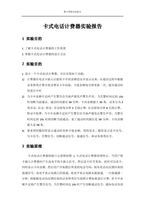
3 实验原理卡式电话计费器的接口示意图如图1卡式电话计费器原理所示,当用户将卡插入计费器时产生高电平的卡插入信号,然后读卡信号变高,此时可以读卡,同时显示卡内余额。
然后用户开始拨打所需的电话号码,则从电话局反馈回来的接通信号,高电平表示电路已经接通,低电平表示电路未被接通。
一旦接通满一分钟,则根据电话局反馈回来的话务种类信号按照计费标准进行计费,若卡中余额不足则产生警告信号,当告警时间达15s时产生切断通话信号,通知电话局切图1卡式电话计费器原理断当前通话,然后告警信号消失;若卡中余额充足,则产生写卡信号,将花费从卡中扣除,并显示当前余额。
同时计费器开始对通话时间进行计时,并显示。
当用户拔出卡之后,卡插入信号变为低电平。
4 实验设计思路该实验由两个模块组成:核心模块是计费计时子模块,完成读卡显示卡内余额,计费,计时,告警等功能。
另有一个分频子模块,将试验箱中的20MHZ系统时钟分频为1KHZ和4HZ,作为扬声器发声的时钟信号以及计时子模块的输入时钟。
FPGA模拟电话计费器设计
《可编辑器件及应用》期末综合设计报告题目:电话计费系统学号:姓名:完成时间:摘要FPGA芯片的集成度越来越高,极大地满足用户的要求,可以用到生活中的各个领域。
现在的可编程逻辑器件稳定性高,代码容易编写和修改。
如verilog HDL代码程序(硬件描述语言),verilog的部分语法是参照C语言的语法设立的(但与C有本质区别),因此,具有很多C语言的优点,从形式表述上来看,verilog代码简明扼要,使用灵活,且语法规定不是很严谨,容易上手。
本系统采用50MZH的脉冲作为内部时钟脉冲,因此要进行分频作为秒脉冲(1HZ)用于计时;本系统还涉及到按键问题,因此要进行按键消抖,我们采用延时的方法作为简单的消抖处理。
关键字:可编程逻辑器件;verilog HDL;脉冲;消抖目录第一章绪论 (1)1.1 FPGA发展及现状 (1)1.2 电话计费器相关背景 (1)1.3 基于FPGA实现电话计费器的方案设计基本原则 (1)1.4 论文主要完成的工作 (1)第二章系统的硬件设计 (2)2.1电话计费器的控制要求 (2)2.2方案设计 (3)2.2.1按键分配 (3)2.2.2按键消抖原理 (3)2.2.3按键消抖原方法 (3)2.3各功能的设计和实现 (4)2.3.1控制与计费模块 (4)2.3.2模块的设计 (5)2.4 控制系统的实现 (6)第三章系统的软件设计 (7)3.1 软件整体设计 (7)3.2 主要模块软件设计 (7)3.3 引脚分配 (10)第四章总结 (11)第五章源程序代码 (12)参考文献 (17)第一章绪论1.1 FPGA发展及现状随着先进科技的发展,计算机仿真与应用技术也在发生着日新月异的变化。
在计算机技术实现重大飞跃的同时,复杂可编程逻辑器件(FPGA)的应用逐步渗透到生产与生活各个方面,给人们生活带来了极大方便。
因其性能的不断提高,应用范围也越来越广。
1.2 电话计费器相关背景在商品经济迅猛发展中,人们对电话的需求日益增长,大力发展和普及公用电话,以满足人们日常生活以及流动人口办理业务之需已成为当前市场趋势。
基于FPGA的通信系统设计

基于FPGA的通信系统设计随着信息技术的发展,通信系统的应用已经渗透到了我们生活的方方面面,从智能手机到物联网,从基站到卫星通信,通信系统无处不在。
如何设计高效、可靠的通信系统成为了通信领域的重要研究方向之一。
本文将探讨基于FPGA的通信系统设计,介绍FPGA的基本概念和通信系统的基础知识,同时结合实际案例,深入分析FPGA的在通信系统中的应用。
一、FPGA的基本概念FPGA是可编程逻辑门阵列(Field-Programmable Gate Array,简称FPGA)的缩写,是由可编程逻辑器件和可编程时钟、存储器等辅助电路组成的可编程集成电路。
与传统的专用集成电路相比,FPGA可以根据需要重复编程,适应不同的应用场景。
FPGA的优点在于其可以完成高速、高精度的数据处理和控制操作,同时具有较强的可靠性和抗干扰能力。
二、通信系统的基础知识通信系统是在信道传输介质上进行信息传输和交换的一种系统,包括发送端、接收端和传输介质。
通信系统的基本要素包括信号源、调制解调器、信道、接收器和信号处理器。
其中,调制解调器是将数字信号转换为模拟信号或者将模拟信号转换为数字信号的重要组成部分。
三、FPGA在通信系统中的应用FPGA在通信系统中的应用非常广泛,从通信协议的实现到信号处理的优化都有涉及。
下面将以LTE无线通信系统为例,介绍其FPGA在通信系统中的应用。
1. 通信协议的实现LTE是一种4G无线通信标准,其通信协议的实现需要高效、稳定的硬件支持。
FPGAs与硬件描述语言(HDL)结合可以实现高度定制化的硬件设计,并且可以通过高层次综合工具转化为可编程逻辑块和可编程时序。
FPGA实现的通信协议处理器可在保证性能和效率的同时保持灵活性,使其适应不同的协议标准。
2. 信号处理的优化FPGA可以对一些通信信号处理算法进行硬件实现,从而提高信号处理的效率和速度。
例如,在LTE中,可以采用FPGA实现高速傅里叶变换(FFT)算法,从而大大提高了LTE信号处理的速度,并且能够保证处理时间的稳定性和可靠性。
基于FPGA的智能网卡设计与实现

基于FPGA的智能网卡设计与实现现今,计算机已经成为生活中不可或缺的一部分,与计算机相关的硬件设备也在不断地更新迭代。
其中,网卡作为计算机中重要的网络通信接口之一,其性能的提升对于整个计算机系统的正常运行和数据传输速度的提升具有重要的影响。
在众多网卡设备中,基于FPGA的智能网卡已经成为越来越受关注的一种高性能的网络通信设备。
本文将详细地介绍基于FPGA的智能网卡的设计与实现。
一、 FPGA及其在网卡设备中的应用FPGA即现场可编程门阵列(Field Programmable Gate Array),它可以实现数字逻辑和数字信号处理应用芯片的自定义电路设计,也可以实现复杂的数字信号处理算法的硬件加速。
FPGA在电子领域中广泛应用,尤其是在计算机中的应用日益广泛。
在网卡设备中,使用FPGA可以使网卡更加智能化,提高其数据处理速度和性能。
比如,在数据包的处理中,FPGA可以快速地进行解析、分类和过滤,减轻传输数据的负担,提高传输速度和吞吐量。
同时,FPGA还可以实现流控制、监控和数据包转发等功能。
二、智能网卡的需求和性能指标随着网络通信的快速发展和数据通信量的增加,传统网卡已经无法满足网络通信的需求。
智能网卡的出现,为网络通信提供了更高性能和更强功能的解决方案。
对于智能网卡的性能指标,主要包括以下几个方面:1. 吞吐量吞吐量是指网卡能够处理的数据量,也反映了网卡的处理速度。
智能网卡一般都有更高的吞吐量,因为它能够更快地处理和传输数据。
2. 处理能力处理能力是指网卡对数据的处理能力。
传统网卡只能进行基本的数据传输,而智能网卡可以进行更加复杂的数据处理,如数据包的解析和分类等,可以大幅提高数据的处理效率。
3. 负载均衡负载均衡是指将网络数据传输有效地分配到多个网络链路上,以提高网络的传输速度和稳定性。
智能网卡可以对数据包进行有效地负载均衡和拥塞控制,使网络传输更加高效。
4. 安全性网络数据的传输安全性非常重要。
电话计费系统开题报告—王远
本科毕业设计开题报告题目:基于FPGA的电话计费系统的设计院(系):电气与信息工程学院班级:电技08-4班姓名:王远学号: 01号指导教师:陈晓洁教师职称:讲师黑龙江科技学院本科毕业设计开题报告题目基于FPGA的电话计费系统的设计来源工程实际1、研究目的和意义当今社会,随着科学技术的发展和信息技术的普及,无论是科研生产还是日常生活,计算机技术已经融入我们的生活,特别是复杂可编程逻辑芯片的应用已经渗透到生产、生活等各个方面,推动了社会发展,尤其在实时控制方面有很强的功能。
通常,我们要实现这些功能可以用单片机来完成,但是,用可编程逻辑FPGA同样可以实现。
我此次要完成的设计是基于FPGA的电话计费系统,这样实时的电话计费系统是企、事业单位信息管理的一个重要组成部分,也是我们现代生活中各种计费电话机中一个重要的组成部分。
目前在中国电信市场上,各大电信运营商充分利用现有网络资源和政策优势,发展IP电话超市、话吧、IP公话直通车,以拓展各运营商的公话市场。
其市场定位主要为流动人口较多、外来人员密集的公共场所,如车站、码头、工业区、租用住宅、大中专院校等。
公话营业厅采用话费预付押金、电脑自动结算等超市型方式进行营业,使运营过程简单、快捷、准确。
2、发展情况(文献综述)随着国内、国际电信技术的迅速发展和广大用户保护自身权益的意识不断增强,人们对各种计费系统的需求越来越多。
计费系统按照规模的大小,可分为大、中、小型三类。
小型的电话计费系统通常是指公共电话的计费系统。
电信计费系统经历了三个历史发展阶段:第一个阶段是“脱机磁带计费”。
当时由于话单采集功能不完善,计费数据需要定期由交换机导入磁带中,再由磁带导入计算机开始计费,实时性差;第二个阶段是“联机实时计费”。
话单采集功能逐步完善,原则上,只要交换机产生话单,计费系统可以立即得到并依据标准费率计费,实时性强,极大地提高了运营商的防欺诈能力;第三个阶段是“个性化服务计费”。
基于FPGA的计价器实验
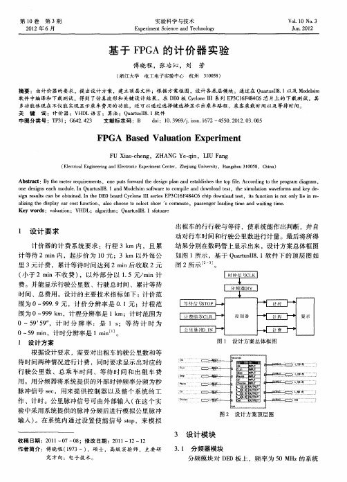
出租车的行行驶与等待 ,使系统能作出判断 ,并 自 动对 行车 时 间和行 驶公 里数进 行计 量 。最后 将所得
结果 分别 在数 码管 上显示 出来 ,设 计方 案 总体框 图
如 图 1 示 ,基 于 Q ats 8 1软 件 下 的顶 层 图 如 所 ur I . uI 图 2所 示 一 引。
FPGA s d Va ua i n Ex e i e t Ba e l to p rm n
FU a — h n Xio c e g, ZHANG - i Ye q n, L U n I Fa g
( lc cl n i e n n l t ncE pr n e t ,Z  ̄i gU ie i ,H nzo 10 8 hn ) Eet a E gn r gadEe r i xe met ne i r ei co i C r h a nvr t n s y aghu3 0 5 ,C ia
( 江大 学 浙 电工 电子 实 验 中心 杭州 305 ) 10 8
摘要 :由计价器的要求 ,提 出设计方案,建立项层文件 ;根据方案框 图,设计各底层模 块。通过在 Q ats 8 1以及 M dlm ur l . uI oes i 软 件 中编译 和 下 栽 测试 ,得 到 了仿 真 波 形 和 关键 设 计 结 果 。 在 D 0板 C c n I E yl eI o I系列 E 3 1F 8C P C 6 44 6芯 片 上 的 下 载 测 试 ,其 多功能体现在不仅能实现显示乘车费用的功能,还 可以通过选择键选择 显示出乘车路程 、乘客乘载时间以及 等待 时间。 关 键 词 :计价器 ;V D H L语 言;算法 ;Q ats 8 1 ur l . 软件 uI 中 图 分 类 号 :T 3 ;G 4 .2 文 献 标 志 码 :B P 1 6 24 3 di 0 3 6 /.sn 17 4 5 .0 2 0 .0 o:1.9 9 ji .62- 5 0 2 1 .3 05 s
电话计费器—电子技术课程设计报告—刘青松

目录一、系统设计 (2)二、硬件软件平台简介 (3)三、模块设计 (3)1. 控制与通话计费模块 (4)2. 报警模块 (7)3. 显示模块 (10)4. 时钟模块 (11)四、系统仿真 (12)1. 控制与通话计费模块 (12)2. 报警模块 (13)3. 其他功能 (13)五、下载调试 (14)六、设计总结 (16)1. 实验简评 (16)2. 心得体会 (16)3. 功能改进与扩展 (16)附录一:系统设计要求 (16)附录二:源代码 (16)一、系统设计本文课程设计根据电话计费器的系统设计要求(具体要求参看后文附录一:系统设计要求),基于FPGA设计实现了该电话计费器,系统设计框图如下图1.1所示。
包括控制与通话计费模块、报警模块,时钟模块和显示模块等四个模块。
图1.1 电话计费器系统设计框图该模拟电话计费器的工作过程为:系统上电,用户打开全局使能开关(模拟用户插入电话卡)后,整个系统开始运行。
当用户此时没有拨通电话时(即系统处于挂断状态),用户可以选择通话类型或进行充值。
当用户拨通电话时(即系统处于通话状态),系统进行通话计时并根据通话的类型进行相应的扣费。
市话为0.1元每分钟,国内长话为1元每分钟,国际长话为2元每分钟,特殊种类电话为1.6元每分钟。
通话类型由用户外部输入。
通话时,系统不断将话费余额与当前所选的通话类型计费率进行比较。
如果当前话费余额不足以通话一分钟,则挂断通话且报警提示;如果话费余额足以通话一分钟但是小于设置的报警值时,系统报警指示灯亮。
否则用户可以正常通话。
话费充值模块为了模拟方便,设置了增减充值方式。
可以通过两个按键分别进行十元加减充值和一元加减充值。
显示模块用来在数码管上显示当前话费余额和已通话时间,通过一个拨动开关切换显示。
系统的主要输入是全局使能信号EN,通话挂断信号RunSet,通话类型Option,加减充值选择AM,切换显示Switch等,主要的输出信号有四个数码管,报警和挂断LED灯,以及通话类型的显示等二、硬件软件平台简介本课程设计的硬件平台选用的是Alter公司的DE0开发板,DE0的芯片为Cyclone III EP3C16F484C6,板上资源还包括50MHz晶振,4个阴极显示数码管,拨动开关和LED灯各10个,3个按键开关等。
基于FPGA的CPCI总线多功能通信卡的设计
编程 门阵 列 ( F i e l d P og r r a mma b l e G a t e Ar r a y, F P G A) 以 其
0 引 言 C P C I 总 线 …是 由 P C I 总 线 发 展 而 来 的 一 种 紧 凑 型
3 2 1 6 4 b i t 局部 总线 , 最高带 宽 可达 5 1 2 MB/ s 。 因 其 具 有
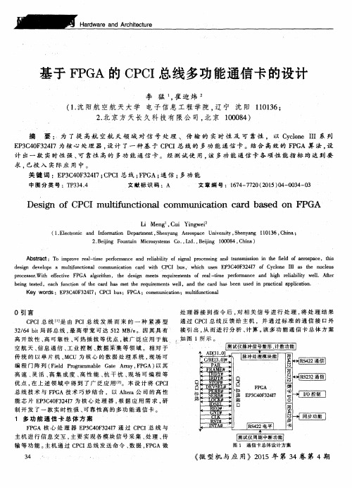
处 理器 接 到指 令后 , 对 相 关信 号 进行 处 理 , 将 处 理 结 果
基于 F P G A的 C P C I 总 线多功 能通信 卡的设计
FPGA模拟电话计费器设计

《可编辑器件及应用》期末综合设计报告题目:电话计费系统学号:姓名:完成时间:摘要FPGA芯片的集成度越来越高,极大地满足用户的要求,可以用到生活中的各个领域。
现在的可编程逻辑器件稳定性高,代码容易编写和修改。
如verilog HDL代码程序(硬件描述语言),verilog的部分语法是参照C语言的语法设立的(但与C有本质区别),因此,具有很多C语言的优点,从形式表述上来看,verilog代码简明扼要,使用灵活,且语法规定不是很严谨,容易上手。
本系统采用50MZH的脉冲作为内部时钟脉冲,因此要进行分频作为秒脉冲(1HZ)用于计时;本系统还涉及到按键问题,因此要进行按键消抖,我们采用延时的方法作为简单的消抖处理。
关键字:可编程逻辑器件;verilog HDL;脉冲;消抖目录第一章绪论 (1)1.1 FPGA发展及现状 (1)1.2 电话计费器相关背景 (1)1.3 基于FPGA实现电话计费器的方案设计基本原则 (1)1.4 论文主要完成的工作 (1)第二章系统的硬件设计 (2)电话计费器的控制要求 (2)方案设计 (3)按键分配 (3)按键消抖原理 (3)按键消抖原方法 (4)各功能的设计和实现 (4)控制与计费模块 (4)模块的设计 (5)2.4 控制系统的实现 (7)第三章系统的软件设计 (8)3.1 软件整体设计 (8)3.2 主要模块软件设计 (8)3.3 引脚分配 (11)第四章总结 (12)第五章源程序代码 (13)参考文献 (18)第一章绪论FPGA发展及现状随着先进科技的发展,计算机仿真与应用技术也在发生着日新月异的变化。
在计算机技术实现重大飞跃的同时,复杂可编程逻辑器件(FPGA)的应用逐步渗透到生产与生活各个方面,给人们生活带来了极大方便。
因其性能的不断提高,应用范围也越来越广。
电话计费器相关背景在商品经济迅猛发展中,人们对电话的需求日益增长,大力发展和普及公用电话,以满足人们日常生活以及流动人口办理业务之需已成为当前市场趋势。
基于FPGA的多功能计价器的设计
维普资讯
经 验 交 流
T ch c m munc to e niaICo ia ins
《 自动 化 技 术 与应 用 》2 0 0 8年 第 2 第 4期 7卷
基 于 F A的 多功 能 计 价 器 的设 计 G P
郑 争 兵
( 陕西理 工学院 电信工程系 , 陕西 汉 中 7 3 0 ) 2 0 3
更 强大 , 计价器 系统将 会变得 更复杂 , 而采用以单片机为 核心控 制模块的设计 方案将很难 满足实 际需要 。F GA P
具 有可编程性 , 开发周期短 , 成化程度 高等特点 , 集 它可 以将部分器件 完成 的功能在 该芯片 内部实 现 , 这样 原有
的 系统体积 大大减小 的 同时还提 高 了系统 的稳定性 … 。
2 2 硬 件设计 .
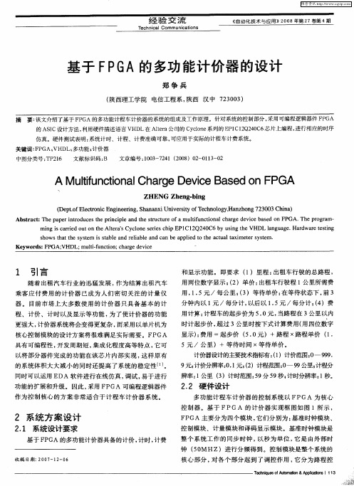
多功 能计程 车计 价器 的控 制 系统 以 FPGA 为核心
控 制 器 。基 于 FPGA 的计价 器 实现框 图如 图 I所 示 ,
作为控 制 核心 的方 案非常适 合 于计程 车计 价器 系 统 。
2 系 统 方案 设计
2 1 系统设计 要求 .
基 于 F GA的多功能计价器具备的计价 , P 计时 , 费 计
摘 要: 该文介绍了基于 F GA的多功能计程车计价器的系统的组成及 工作原理 。针对 系统的控制部分 , P 采用可编程逻辑器件 F G P A 的 AS C设计方法 , I 利用硬件描述语言 VHD L在 Al r 公 司的 C co e ta e y ln 系列的 E 1 2 4 C P C1Q2 0 6芯片上编程 , 进行相应的时序 仿真 。硬件测试表 明: 系统计时 、计程 、计费准确可靠 , 可应用于实 际的计程车计费系统 。 关键词 : P A; F G VHD 多功能 ; L; 计价器 中图分类号 : P 1 T 26 文献标识码 : B 文章编号 :0 3 74 2 0 )0 —0 — 2 10 — 2 1(0 8 2 13 0 l
基于FPGA的电话卡计费器设计 英文翻译
武汉工业学院毕业设计(论文)外文参考文献译文本2013届原文出处T.J.byers Electronic Test Equipment-principlesand Applications毕业设计(论文)题目基于FPGA的电话卡计费器设计院(系)电气与电子工程学院专业名称电子信息科学与技术学生姓名学生学号指导教师译文要求:1、译文内容须与课题(或专业)有联系;2、外文翻译不少于4000汉字。
PLC technique discussion and future developmentT.J.byers Electronic Test Equipment-principles and Applications. PrincetonUniversity. America.With the development of the times, today’s technology are maturing,competition intensified, only by manual operation has not satisfied with the current manufacturing industry prospects, but also can’t guarantee higher quality requirements and the image of high-tech enterprises.People see in the production practice, automation has brought great convenience and product quality assurance to the people, but also reduce the labor intensity, reduce the establishment on the personnel. It is difficult to realize in many complex processes in the target control, overall optimization, optimal decision-making, skillful workers, technicians or experts, managers are able to judge and operate easily, can obtain satisfactory results. Research on the goal of artificial intelligence is the use of computer to realize, simulation of these intelligent behavior, the human brain and computer coordinated work, to the man-machine combination model, to find the best way to solve complex problems.We see the connection of the control relay on various occasions, it is the era of the past, today's relay only as a low-end of the primary control module or a simple device to use; and PLC has also become a landmark theme, through interspersed extremely stable hardware and flexible software control, automation to a new the climax.The PLC biggest characteristics lie in: the electrical engineering teacher already no longer electric hardware up too many calculations of cost, as long as order the importation that the button switch or the importation of the sensors order to link the PLC up can solve problem, pass to output to order the conjunction contact machine or control the start equipment of the big power after the electric appliances, but the exportation equipment direct conjunction of the small power can.PLC internal containment have the CPU of the CPU, and take to have an I/ O for expand of exterior to connect a people's address and saving machine three big pieces to constitute, CPU core is from an or many is tired to add the machine to constitute, mathematics that they have the logic operation ability, and can read the procedure save the contents of the machine to drive the homologous saving machine and I/ O to connect after pass the calculation; The I/ O add inner part is tired the input and output system of the machine and exterior link, and deposit the related data into the procedure saving machineor data saving machine; The saving machine can deposit the data that the I/ O input in the saving machine, and in work adjusting to become tire to add the machine and I/ O to connect, saving machine separately saving machine RAM of the procedure saving machine ROM and data, the ROM can do deposit of the data permanence in the saving machine, but RAM only for the CPU computes the temporary calculation usage of hour of buffer space.The PLC anti- interference is very and excellent, our root need not concern its service life and the work situation bad, these all problems have already no longer become the topic that we fail, but stay to our is a concern to come to internal resources of make use of the PLC to strengthen the control ability of the equipment for us, make our equipment more gentle.PLC language is not we imagine of edit collected materials the language or language of Cs to carry on weaving the distance, but the trapezoid diagram that the adoption is original after the electric appliances to control, make the electrical engineering teacher while weaving to write the procedure very easy comprehended the PLC language, and a lot of non- electricity professional also very quickly know and go deep into to the PLC.Is PLC one of the advantage above and only, this is also one part that the people comprehend more and easily, in a lot of equipment, the people have already no longer hoped to see too many control buttons, they damage not only and easily and produce the artificial error easiest, small is not a main error perhaps you can still accept; But lead even is a fatal error greatly is what we can't is tolerant of. New technique always for bringing more safe and convenient operation for us, make we a lot of problems for face on sweep but light, do you understand the HMI? Says the HMI here you basically not clear what it is, also have no interest understanding, change one inside text explains it into the touch to hold or man-machine interface you knew, it combine with the PLC to our larger space.HMI control not only is reduced the control button, to increase the flexibility of control, more main of it is can sequence, and can change the feedback data input and data output, but also can be displayed directly in the simulation of temperature control curve. And be able to write functions to help do everything in one's power to provide all kinds of help, allowing the operator to reduce unnecessary mistakes. Currently the HMI factory is also more and more, the function is also more and more strong, the price is also more and more low, the use of more and more widely. The prospect of HMI can say very goods.At a lot of situations, the list is a smooth movement that can't guarantee the equipment by the control of the single machine, but pass the information exchanges of the equipment and equipment to attain the result that we want. For example fore pack and the examination of the empress work preface, we will arrive wrapping information feedback to examine theplace, and examine the information of the place to also want the feedback to packing. Pass the information share thus to make both the chain connect, becoming a total body, the match of your that thus make is more close, at each other attain to reflect the result that mutually flick.The PLC correspondence has become more and more manifest its value, at the PLC and correspondence between PLCs, can pass the communication of the information and the share of the data to guarantee that of the equipment moderates mutually, the result that arrive already to repair with each other. Data conversion the adoption RS232 between PLC connect to come to the transmission data, but the RS232 pick up a people and can guarantee 10 meters only of deliver the distance, if in the distance of 1000 meters we can pass the RS485 to carry on the correspondence, the longer distance can pass the MODEL only to carry on deliver.The form that information transport contain single work, the half a work and the difference of a works .The meaning of the single work also is to say both, a can send out only, but a can receive only, for example a spy he can receive the designation of the superior only, but can't give the superior reply; A work of half is also 2 and can send out similar to accept the data, but can't send out and accept at the same time, for example when you make a phone call is to can't answer the phone, the other party also; But whole pair works is both can send out and accept the data, and can send out and accept at the same time. Be like the Internet is a typical example.The process that information transport also has synchronous and different step cent: The data line and the clock lines are synchronous when synchronous meaning lie in sending out the data, is also the data signal and the clock signals to be carry on by the CPU to send out at the same time, this needs to all want the specialized clock signal each other to carry on the transmission and connect to send, and is constrained, the characteristics of this kind of method lies in its speed very quick, but correspond work time of take up the CPU and also want to be long oppositely, at the same time the technique difficulty also very big. Its request lies in can't thing have an error margins in a data deliver, otherwise the whole data error will occur; there is a big difficulty in hardware. Applied more and more extensive in some appropriative equipment, be like the appropriative medical treatment equipment, the numerical signal equipment...etc., in compare the one data deliver, its result is very good.And the different step is an application the most extensive, this receive benefit in it of technique difficulty is opposite and want to be small, at the same time not need to prepare the specialized clock signal, its characteristics to lie in, its data is partition, the long-lostsend out and accept, be the CPU is too busy of time can grind to a stop sex to work, also reduced the difficulty on the hardware, the data throw to lose at the same time opposite want to be little, we can pass the examination of the data to observe whether the data that we send out has the mistake or not, be like strange accidentally the method, tired addition and eight efficacies method etc., can use to helps whether the data that we examine to send out have or not the mistake occurrence, pass the feedback to carry on the discriminator.A line of transmission of the information with serial and parallel port of: the usual PLC is 8, there are 16 machines. We can when sending data is a send out to each other, can be 8 bit 8 bit data will be sent to the other side, a bit and 8 bit difference is what we say to send out the data and combine sends out the data. Speed is more and slowly, but as long as two or three lines can solve problem, and can use the telephone line to carry out remote control. But combine the ocular transmission speed is fast, it is 256 times of the serial port, occupy the advantage in the short distance, as is the TTL level, generally limited to a range of 1 meters, it is not suitable for long distance data transmission, thus the cost is too expensive.In many cases we like using serial-parallel conversion chip for transmission, in this case we do not need to be too complicated register set, and directly through the data transfer instruction for data communication, but communication is not a very viable option, because when sending data to each other's PLC must have been waiting for your data output, it can't do other work.When you read a book in time, you hear someone knocking at the door, you stop to the matter at hand, to open the door, and knocked at the door of dialogue, when the phone rang, you pick up the phone, sketch in finish after a phone call, come back to the same door to continue dialogue, dialogue, you can continue after reading your book, that we call it the interrupt, it has the authority, but also has priority, PLC has such functions. The utility model is characterized in that we may encounter emergency in the operation of equipment, we should immediately stop the work on the hand, to deal with more important things, this is we often encountered, PLC to implement emergency task, will save the current state, such as program the address, CPU accumulator data, as we went to open the door to jot down the books we read in the first few pages or simply make a mark, because we're going to continue to look at the back of the book. CPU always follow our willingness to do what is right, but you want a thing to it is wrong, it also would be same to do, this we must notice.The interruption is not only a, sometimes at the same time, there are several interrupt, interrupt priority level is interrupted, they will to implement higher level according to therequirements of the. This interrupts in the form of interrupt nesting. Of course, the interrupt level according to various resources of CPU with internal PLC related, but also with the size of stack is also related to.The contents that break off has a lot of kinds, for example the exterior break off, correspondence in of send out and accept the interruption and settle and the clock that count break off, still have the WDT to reset the interruption etc., they enriched the CPU to respond to the category while handle various business. Speak thus perhaps you can't comprehend the internal structure and operation orders of the interruption completely also, we do a very small example to explain.Each device is always not forget there is a button, it is also used in the US in case of emergency, the emergency stop button. When we meet the Human body trouble and surprised circumstances we as long as press it, the machine stops all operations immediately, and wait for processing the over surprised empress recover the operation again. Nasty stop the internal I/ O of the internal CPU of the button conjunction PLC to connect up, be to press button an exterior to trigger signal for CPU, the CPU carries on to the I/ O to examine again, being to confirm to have the exterior to trigger the signal, CPU protection the spot breaks off procedure counts the machine turn the homologous exterior I/ O automatically in the procedure to go to also, be exterior interruption procedure processing complete, the procedure counts the machine to return the main procedure to continue to work. Have 1:00 can what to explain is we generally would nasty stop the button of exterior break off to rise to the tallest Class, thus guarantee the safety.When we are work a work piece, giving the PLC a signal, counting PLC inner part the machine add 1 to compute us for a day of workload, a count the machine and can solve problem in brief, certainly they also can keep the data under the condition of dropping the electricity, urging the data not to throw to lose, this is also what we hope earnestly.The PLC still has the function that the high class counts the machine, being us while accept some data of high speed, the high speed that here say is the data of the in all aspects tiny second class, for example the bar code scanner is scanning the data continuously, calculating high-speed signal of the data processor DSP etc., we will adopt the high class to count the machine to help we carry on count. It at the PLC carries out the procedure once discover that the high class counts the machine to should of interruption, will let go of the work on the hand immediately. The trapezoid diagram procedure that passes by to weave the distance again explains the high class for us to carry out procedure to count machine would automatic performance to should of work, thus rise the Class that the high class counts the machine to high one Class.The PLC development has already entered for network ages of correspondence from the mode of the one, and together other works control the net plank and I/ O card planks to carry on the share easily. A state software can pass all se hardware link, more animation picture of keep the view to carries on the control, and cans pass the Internet to carry on the control in the foreign land, the blast-off that is like the absolute being boat No.5 is to adopt this kind of way to make airship go up the sky.The development of the higher layer needs our continuous effort to obtain. The PLC emergence has already affected a few persons fully, we also obtained more knowledge and precepts from the top one experience of the generation, coming to the continuous development PLC technique, push it toward higher wave tide.可编程控制器技术讨论与未来发展T.J.byers电子测试设备原理和应用.美国普林斯顿大学随着时代的发展,当今的技术也日趋完善、竞争愈演愈烈,单靠人工的操作已不能满足于目前的制造业前景,也无法保证更高质量的要求和高新技术企业的形象。
verilog电话计费器课程设计
verilog电话计费器课程设计一、课程目标知识目标:1. 学生能够理解Verilog硬件描述语言的基本概念,掌握其语法和结构;2. 学生能够运用Verilog语言设计简单的电话计费器模块;3. 学生了解电话计费器的基本工作原理,掌握其关键功能模块的设计与实现;4. 学生了解数字系统设计的基本流程,包括设计、仿真和验证。
技能目标:1. 学生能够运用Verilog语言编写代码,实现电话计费器的计时、计费功能;2. 学生能够使用相关设计工具进行数字电路的仿真和验证;3. 学生能够运用所学知识解决实际问题,具备一定的数字系统设计能力;4. 学生能够通过课程学习,提高团队协作和沟通能力。
情感态度价值观目标:1. 学生培养对数字电路设计的兴趣,激发创新思维;2. 学生树立正确的价值观,认识到技术发展对生活的影响;3. 学生培养团队协作精神,学会尊重和倾听他人意见;4. 学生通过课程学习,增强自信心,勇于面对挑战和解决问题。
课程性质:本课程为电子信息类专业高年级选修课程,旨在培养学生的数字系统设计能力和实践操作技能。
学生特点:学生已具备一定的数字电路基础知识,具有一定的编程能力和实际操作能力。
教学要求:结合课程性质和学生特点,注重理论与实践相结合,提高学生的实际操作能力和创新能力。
通过课程目标的具体分解,实现对学生知识、技能和情感态度价值观的全面提升。
二、教学内容1. Verilog语言基础:包括数据类型、运算符、控制语句、模块和端口定义等基本概念,对应教材第二章内容。
2. 电话计费器原理:介绍电话计费器的基本工作原理,分析计费算法,对应教材第四章内容。
3. 数字系统设计流程:讲解数字系统设计的基本流程,包括需求分析、设计、仿真和验证,对应教材第五章内容。
4. Verilog编程实践:以电话计费器为例,教授Verilog编程技巧,包括模块划分、代码编写和调试,对应教材第六章内容。
5. 电话计费器模块设计:详细讲解计时、计费等功能模块的设计与实现,对应教材第七章内容。
基于FPGA的计价器实验
基于FPGA的计价器实验傅晓程;张冶沁;刘芳【摘要】由计价器的要求,提出设计方案,建立项层文件;根据方案框图,设计各底层模块。
通过在QuartusⅡ8.1以及Modelsim软件中编译和下栽测试,得到了仿真波形和关键设计结果。
在DE0板CycloneⅢ系列EP3C16F484C6芯片上的下载测试,其多功能体现在不仅能实现显示乘车费用的功能,还可以通过选择键选择显示出乘车路程、乘客乘载时间以及等待时间。
%By the meter requirements, one puts forward the design plan and establishes the top file. According to the program diagram, one designs each module. In QuartusⅡ8. 1 and Modelsim software to compile and download test, the simulation waveforms and key design results can be obtained. In the DE0 board Cyclo ne Ⅲ series EP3C16F484C6 chip download test, its function is not only lie in realizing the display car cost function, also choose to select show's commute, passenger loading time and waiting time.【期刊名称】《实验科学与技术》【年(卷),期】2012(010)003【总页数】3页(P13-14,18)【关键词】计价器;VHDL语言;算法;QuartusⅡ8.1软件【作者】傅晓程;张冶沁;刘芳【作者单位】浙江大学电工电子实验中心,杭州310058;浙江大学电工电子实验中心,杭州310058;浙江大学电工电子实验中心,杭州310058【正文语种】中文【中图分类】TP31;G642.423计价器的计费系统要求:行程3 km内,且累计等待2 min内,起步价为10元;3 km以外每公里3元计费,累计等待时间达到2 min后收取2元(小于2 min不收费),以外部分以1.5元/min计费。
基于FPGA的电话卡计费器设计毕业设计论文
毕业设计(论文)设计(论文)题目: 基于FPGA的电话卡计费器设计毕业设计(论文)原创性声明和使用授权说明原创性声明本人郑重承诺:所呈交的毕业设计(论文),是我个人在指导教师的指导下进行的研究工作及取得的成果。
尽我所知,除文中特别加以标注和致谢的地方外,不包含其他人或组织已经发表或公布过的研究成果,也不包含我为获得及其它教育机构的学位或学历而使用过的材料。
对本研究提供过帮助和做出过贡献的个人或集体,均已在文中作了明确的说明并表示了谢意。
作者签名:日期:指导教师签名:日期:使用授权说明本人完全了解大学关于收集、保存、使用毕业设计(论文)的规定,即:按照学校要求提交毕业设计(论文)的印刷本和电子版本;学校有权保存毕业设计(论文)的印刷本和电子版,并提供目录检索与阅览服务;学校可以采用影印、缩印、数字化或其它复制手段保存论文;在不以赢利为目的前提下,学校可以公布论文的部分或全部内容。
作者签名:日期:学位论文原创性声明本人郑重声明:所呈交的论文是本人在导师的指导下独立进行研究所取得的研究成果。
除了文中特别加以标注引用的内容外,本论文不包含任何其他个人或集体已经发表或撰写的成果作品。
对本文的研究做出重要贡献的个人和集体,均已在文中以明确方式标明。
本人完全意识到本声明的法律后果由本人承担。
作者签名:日期:年月日学位论文版权使用授权书本学位论文作者完全了解学校有关保留、使用学位论文的规定,同意学校保留并向国家有关部门或机构送交论文的复印件和电子版,允许论文被查阅和借阅。
本人授权大学可以将本学位论文的全部或部分内容编入有关数据库进行检索,可以采用影印、缩印或扫描等复制手段保存和汇编本学位论文。
涉密论文按学校规定处理。
作者签名:日期:年月日导师签名:日期:年月日注意事项1.设计(论文)的内容包括:1)封面(按教务处制定的标准封面格式制作)2)原创性声明3)中文摘要(300字左右)、关键词4)外文摘要、关键词5)目次页(附件不统一编入)6)论文主体部分:引言(或绪论)、正文、结论7)参考文献8)致谢9)附录(对论文支持必要时)2.论文字数要求:理工类设计(论文)正文字数不少于1万字(不包括图纸、程序清单等),文科类论文正文字数不少于1.2万字。
基于FPGA的电话计费器的设计
基于FPGA的电话计费器的设计
周鼎舜;覃秋荣;王颖
【期刊名称】《电子测试》
【年(卷),期】2021()23
【摘要】现代社会离不开即时通讯工具,科学准确的计费装置的应用范围越来越广泛。
电话计费器在现代化社会中具有广泛的应用价值。
本文以FPGA技术位平台,以 Verilog HDL/硬件逻辑语言为基础设计了电话计费器,具有菜单模块,设置余额模块,翻译显示模块,时间模块,分频模块,调试模块,通话种类模块,通话模块。
完成了模拟通话过程中的计费功能,经过验证具有实际应用价值。
【总页数】4页(P16-18)
【作者】周鼎舜;覃秋荣;王颖
【作者单位】大连理工大学城市学院
【正文语种】中文
【中图分类】TP3
【相关文献】
1.基于FPGA实时电话计费器的设计
2.基于FPGA芯片设计出租车计费器的研究
3.基于CPLD/FPGA的出租车计费器系统的设计实现
4.基于FPGA的出租车计费器系统的设计
5.基于FPGA的出租车计程计费器项目教学设计
因版权原因,仅展示原文概要,查看原文内容请购买。
基于FPGA的出租车计程计费器项目教学设计
基于FPGA的出租车计程计费器项目教学设计一、项目背景随着社会的快速发展,出租车已经成为了人们生活中不可或缺的交通工具。
在出租车计费方面,人们希望有一种简单、准确的计费方式来确保费用的公平和合理。
出租车计程计费器成为了一个十分重要的设备。
本项目旨在利用FPGA(现场可编程门阵列)技术设计一个出租车计程计费器,通过该项目的设计和实现,使学生学习到FPGA的应用技术,并深入理解计费器的工作原理和实现方式。
二、项目目的1. 熟悉FPGA的基本知识和原理。
2. 掌握FPGA在计程计费器中的应用。
3. 了解并掌握计费器的设计和实现原理。
4. 培养学生的逻辑分析和问题解决能力。
四、项目实施1. 项目准备(1)了解FPGA的基本原理和应用。
(2)学习计费器的设计原理和实现方式。
(3)熟悉Verilog语言的基本语法和特性。
(4)准备实验所需的硬件设备和软件工具。
2. 项目实施步骤(1)阅读FPGA的相关资料,了解其基本原理和应用领域。
(2)学习计费器的设计原理,包括计费规则、时间计费、里程计费等内容。
(3)学习Verilog语言的基本语法和特性,准备设计所需的代码。
(4)使用Verilog语言设计计费器的模块,包括显示模块、计费规则模块、计时模块、计程模块等。
(5)将设计好的模块进行综合,并生成比特流文件。
(6)将比特流文件下载到FPGA开发板中,进行功能测试和验证,调试程序以确保其正常工作。
3. 项目测试和验证(1)进行基本的功能测试,包括计费器的显示、计时和计费功能。
(2)验证计费器的准确性和稳定性,例如检查计费规则是否正确、计时是否准确、显示是否清晰等。
(3)修改和调试程序,解决可能出现的问题和bug。
5. 实验报告(1)撰写实验报告,包括项目背景、目的、内容、实施步骤、测试验证结果等内容。
(2)总结项目的收获和经验,提出改进建议和展望。
六、项目评估通过对项目实施过程的评估,对学生的技术水平、工作态度和团队合作能力进行综合评价,为学生提供个性化的指导和辅导。
FPGA课设 手机自动拨号器
1.绪论1.1 FPGA简介FPGA(Field-Programmable Gate Array),即现场可编程门阵列,它是在PAL、GAL、CPLD等可编程器件的基础上进一步发展的产物。
它是作为专用集成电路(ASIC)领域中的一种半定制电路而出现的,既解决了定制电路的不足,又克服了原有可编程器件门电路数有限的缺点。
以硬件描述语言(Verilog或VHDL)所完成的电路设计,可以经过简单的综合与布局,快速的烧录至 FPGA 上进行测试,是现代 IC设计验证的技术主流。
这些可编辑元件可以被用来实现一些基本的逻辑门电路(比如AND、OR、XOR、NOT)或者更复杂一些的组合功能比如解码器或数学方程式。
在大多数的FPGA里面,这些可编辑的元件里也包含记忆元件例如触发器(Flip-flop)或者其他更加完整的记忆块。
时至今日,FPGA(现场可编程逻辑器件)产品的应用领域已经从原来的通信扩展到消费电子、汽车电子、工业控制、测试测量等广泛的领域。
而应用的变化也使FPGA产品近几年的演进趋势越来越明显:一方面,FPGA供应商致力于采用当前最先进的工艺来提升产品的性能,降低产品的成本;另一方面,越来越多的通用IP(知识产权)或客户定制IP 被引入FPGA中,以满足客户产品快速上市的要求。
此外,FPGA企业都在大力降低产品的功耗,满足业界越来越苛刻的低功耗需求。
1.2 Altera Quartus II简介Altera Quartus II 是一种可编程逻辑的设计环境, 由于其强大的设计能力和直观易用的接口,越来越受到数字系统设计者的欢迎。
当前官方提供下载的最新版本是v13.0。
Altera Quartus II (3.0和更高版本)设计软件是业界唯一提供FPGA和固定功能HardCopy器件统一设计流程的设计工具。
工程师使用同样的低价位工具对 Stratix FPGA 进行功能验证和原型设计,又可以设计HardCopy Stratix器件用于批量成品。
- 1、下载文档前请自行甄别文档内容的完整性,平台不提供额外的编辑、内容补充、找答案等附加服务。
- 2、"仅部分预览"的文档,不可在线预览部分如存在完整性等问题,可反馈申请退款(可完整预览的文档不适用该条件!)。
- 3、如文档侵犯您的权益,请联系客服反馈,我们会尽快为您处理(人工客服工作时间:9:00-18:30)。
注:1、课题类型:设计或论文。
2、课题来源:纵向、横向或自拟课题,对于纵向和横向课题并要用括号括起填写确切基金项目、企事业单位项目。
一般情况下,利用EDA技术进行电子系统设计,最终目标是完成专用集成电路ASIC的设计和实现。基于可编程器件EDA技术主要包括如下四个要素:
(1)大规模可编程器件
可编程逻辑器件(PLD,Programmable Logic Device)即部分功能可由软件程序更改的器件。它是当前数字系统设计的主要硬件基础,是硬件编程语言VHDL的物理实现工具。可编程逻辑器件使用计算机,利用软件,硬件对器件进行系列编程,然后通过程序指挥芯片配置连线和编程器件,把应连接的元件,单元连接起来。根据用户编写的不同程序就可以制造出有不同电路功能的器件。并在设计阶段进行仿真(Emulation)使得微电子设计实现了早期集成和软硬件联合验证。
2013年4月26日-5月20日完成设计方案,具体算法,编写出电梯控制器的VHDL程序,并通过MAX+plus II软件仿真验证其正确性
2013年5月20-5月27日利用EDA实验平台对该设计进行模拟测试
2013年5月28日-6月7日完成课题设计,总结写论文
参考文献
[1]张亦华,延明,肖冰.数字逻辑器设计实验技术与EDA工具.北京:北京邮电大学出版社,2003.
1.FPGA背景
FPGA是英文Field Programmable Gate Array的缩写,即现场可编程门阵列,它是在可编程阵列逻辑PAL(Programmable Array Logic)、门阵列逻辑GAL(Gate Array Logic)、可编程逻辑器件PLD(Programmable Logic Device)等可编程器件的基础上进一步发展的产物。它是作为专用采集成电路ASIC(Application Specific Integrated Circuit)领域中的一种半定制电路而出现的,即解决了定制电路的不足,又克服了原有可编程器件门电路数有限的缺点。FPGA能完成任何数字器件的功能,上至高性能CPU,下至简单的74系列电路,都可以用FPGA来实现。FPGA如同一张白纸或是一堆积木,工程师可以通过传统的原理图输入法,或是硬件描述语言自由设计一个数字系统。通过软件仿真,我们可以事先验证设计的真确性。在PCB完成以后,还可以利用FPGA的在线修改能力,随时修改设计而不必改动硬件电路。使用FPGA来开发数字电路,可以大大缩短设计时间,减少PCB面积,提高系统的可靠性。PLD的这些优点使得PLD技术在90年代以后得到飞速的发展,同时也大大推动了电子设计自动化EDA软件和硬件描述语言VHDL的进步。
当前,EDA的主要应用方向为微控制器,ASIC和DSP等方面。
1.电话卡计费器设计原理
(1)根据电话局反馈回来的信号,代表话务种类(放回信号可自己输入),“00”表示特殊类电话,“01”表示市话,“10”表示国内长话,“11”表示国际长话;并用DE2板上的两个数码管用来显示通话为何种类型。
(2)利用DE2板上的两个数码管用来显示卡内余额(可自己设定初始余额),其单位为元,这里假定能显示的最大数额为10元。余额根据打市话每分钟0.1元,打国内长话1元,打国际长话2元,打特殊电话1.6元来计算。
武汉工业学院
毕业设计(论文)开题报告
设计(论文)题目:基于与电子工程学院
专业名称电子信息科学与技术
学生姓名
学生学号
指导教师
武汉工业学院毕业设计(论文)学生开题报告表
课题名称
基于FPGA的电话卡计费器设计
课题类型
设计
课题来源
纵向
导师
学生姓名
学号
专业
电子信息科学
开题报告内容:(调研资料的准备,目的、要求、思路与预期成果;任务完成的阶段、内容及时间安排;完成设计(论文)所具备的条件因素等。)
1.实验设备
目前配备1G内存,联想笔记本电脑配置高,上机时间充足。
要求:
MAX+plus II软件一套;EDA实验(开发)平台一套,提高计算机配置,增加上机时间。
2.可能遇到的问题
对Verilog HDL语言还不够熟练,对编程环境比较陌生。
3.时间安排
2013年4月18日-4月25日查阅资料,进一步熟悉Verilog HDL编程,熟悉MAX+plus II软件的应用
(3)显示本次通话的时长。
(4)余额过少时的警告信号。当打市话时,余额少于0.2元,打国内长话时,余额少于2元,打国际长话时,余额少于4元,打特殊电话时,余额少于3.2元,即会产生信号警告。
(5)当警告时间过长(如超过1分钟)时自动切断通话信号。
2.各功能模块的设计和实现
(1)控制与计费模块
计费计时模块是整个IC电话计费器的核心部分。它主要完成用户通话过程的计时、计费功能,且能够根据当前通话的种类(国际长途2元/分,国内长途1元/分、市话0.1元/分、特话1.6元/分)进行相应的扣费。
MAX+PLUS II具有以下特点:①开放的接口。②与结构无关(指VHDL描述逻辑综合前与结构无
关)。③多平台。④完全集成化。⑤多种设计库。⑥模块化工具。⑦硬件描述语言(HDL)。⑧开放核的特点。⑨Megacore功能。
(4)实验开发工具
利用EDA技术进行电子系统设计的下载与硬件验证工具,主要包括:①实验或开发所需的各类信号模块,包括时钟、脉冲、高低电平等;②通用数字式和扫描驱动类接口,包括各类输入显示或指示模块;③模拟器件及接口,包括模拟信号的放大,比较及A/D转换模块;④监控程序模块;⑤目标芯片适配座以及FPGA/CPLD目标芯片和编程下载电路。
2.软件编程思路
开关一拨上以后,采用数码管显示卡的余额,这时候不计费.系统采用两个开关控制话务种类(返回信号可自己输入),“00”表示特殊电话,“01”表示市话,“10”表示国内长话,“11”表示国际长话;并用DE2板上的两个数码管来显示通话为何种类型;当两开关都没拨通时,处于未通话状态,系统只显示余额,不计费;当开关拨至01,处于市话状态中,拨通后,按市话通话系统计费;当开关拨至10,处于国内长途通话状态,拨通之后,采取长途计费方式;开关拨至11,处于国际长途通话状态,拨通之后,采取特别话费计费方式。
(2)显示模块
该模块经过3选1选择器将余额信息(4位BCD码以元为单位)、计时信息动态显示输出。
(3)报警模块
该模块的功能是产生光报警信号,提示用户卡内余额不足。
1.软件整体设计
本系统设计的系统组成框图包括三个模块:控制与计费模块、显示模块和报警模块。控制与计费模块完成计费功能并产生控制信号,控制另外两个模块。显示模块动态显示通话时间与通话余额计费等信息。报警模块是根据通话中出现的报警信息,及时给出声、光或者声光报警。本系统采用Verilog HDL硬件描述语言进行设计。
(3)软件开发工具
MAX+PLUS II是Altera公司的第三代CPLD开发工具软件,它集成了可编程逻辑器件的设计环境。它可以在多种平台上运行提供了灵活和高效的界面。设计者无需精通器件内部的复杂结构,只需用自己熟悉的设计输入工具(原理图,波形图或硬件描述语言等)进行设计输入。MAX+PLUS II将这些设计软件换成目标结构所要求的格式,从而使设计者能够轻松的掌握和使用MAX+PLUS II软件。
CPLD实际是一个子系统部件,具有可编程性和实现方案容易改动的特点。它具有更高的集成度,它允许更多的输入信号,乘积和宏单元。CPLD内含多个I/O块和逻辑块。这些逻辑块可以使用可编程内连线的布线来实现相互间联系。每一个逻辑块就相当于一片220V10和236V18的PLD。有乘积阵列,乘积项分配机构和宏单元。I/O块通常具有逻辑功能和较强的I/O控制功能。目前大部分CPLD器件还具有兼容于IEEE1149.1(JTAG)标准测试激励端和边界扫描能力,以及兼容于PCI接口协议的输入输出缓冲器。
[2]李洪国,沈明山.可编程器件EDA技术与实践.北京:机械工业出版社
[3]甘历. VHDL应用与开发实践.北京:科学出版社,2003.
[4]潘松,黄继业. EDA技术实用教程.北京:科学出版社
[5]Mark Zwolinski. VHDL数字系统设计[英].北京:电子工业出版社,2002.
指导教师签名:日期:
2.EDA背景
EDA技术是现代电子信息工程领域的一门新技术,同时也是现代电子设计技术和电子制造技术的核心。EDA技术是依赖功能强大的计算机,在EDA工具软件平台上开发出来的一整套电子系统设计的软硬件工具,并提供了先进的电子系统设计方法。
未来EDA技术将向深度和广度两个方面发展,有专家认为,21世纪将是EDA技术快速发展的时期,并且EDA技术将是对21世纪产生重大影响的十大技术之一。
(2)硬件描述语言
硬件描述语言(HDL)是一种用文本形式来描述和设计电路的语言,它可以使电子系统设计者利用这种语言来描述自己的设计思想和电子系统的行为并建立模型,然后利用EDA工具进行仿真,自动综合到门级电路,可用ASIC或CPLD/FPGA实现其功能。目前其中最有代表性的是美国国防部开发VHDL(Very-High-Speed Integrated Circuit HDL),Verilog公司开发的Verilog HDL。HDL(IEEE1164)和Verilog HDL(IEEE1364)被IEEE列为工业标准,被众多EDA工具所支持,在电子工程领域,已成为事实上通用的HDL。将担负几乎全部的数字系统设计任务。