AzLM型计轴系统安装调试手册(V1.1)
城市轨道交通计轴设备认识及维护

件。 ➢ 检查室外磁头是否有损坏。如有损坏,更换磁头。 ➢ 排除故障后,进行区段复零操作。
2.一个或几个计轴轨道继电器落下 故障查找:计轴系统的故障一般由信号员发现一个区段无车但是却
显示占用,并且不能复零。 ➢ 定位室外计轴点及室内相应的串口板、并口板 ➢ 确定是否是由磁头故障或者位置不合适引起的瞬时故障。 ➢ 确定是否是由于通信中断,检测点断电,或者检测点故障。 ➢ 检查室内相关串口板,并口板工作状态,如有故障,更换相应器
任务1 计轴设备基本组成
磁头
室外电子盒
室内主机
室外钢轨上安装两个磁头,其作用: 1、有效计轴,检查空闲、占用状态; 2、鉴别列车运行方向。
磁头部分名称
枕木 钢轨 发送磁头 接收磁头 磁头电缆 防护套管 托架
完整的磁头电缆
轨道磁头
No
黄帽子
Image
安装基座
室外电子单元
电子盒 支座
安装基座
ACE室内主机
件。 ➢ 检查室外计轴点模拟板、评估板工作状态,如有故障,更换相应器
件。 ➢ 检查室外磁头是否有损坏。如有损坏,更换磁头。 ➢ 排除故障后,进行区段复零操作。
三、故障维护工作注意事项
1、故障维护工作必须执行铁路运营的有关规章制度,以确保行车及人身 安全。
2、ACE主机电源板、CPU板不支持热插拔; 串口板、并口板以及室外计轴点EAK模拟板、评估板支持热插拔; ACE主机重启前至少断电30秒。
室外计轴点电源DC120V 轨道继电器电源DC24V
更换故障板卡
检查计轴主机的电 源板及CPU板指示
灯状态
定位室外计轴点及 室内相应的串口 板、并口板
AzLM计轴系统简介_MOR_080917

Az LM系统的应用情况(国内)
AzLM在国内已开通线路: 上海地铁6号线 上海地铁8号线 上海地铁9号线
AzLM在国内在建线路: 上海地铁7号线 上海地铁10号线 上海地铁11号线 北京地铁4号线 广州地铁5号线车辆段
17 TTACS Market Dept. 2008
电源数字结合单元
Az LM A C E 主机
区段轨道继电器 信号联锁设备
直流 120V 直流 60V
信号电源屏 直流 24V
AzLM系统配置举例
AGJ
ACE主机1 ACE主机2
BGJ
AG
BG
A联锁区域 联锁区域内计轴设备连接示意图
13 TTACS Market Dept. 2008
AzLM系统配置举例
人工确认,区间才会空闲
9 TTACS Market Dept. 2008
AzLM复零方式
有条件直接复零
执行复零前,调度员必须确保区间内无车辆 当区间确实处于被占用状态时,只有在最后一个计数动作
为离开区间的计数时,才能执行复零(有条件复零) 当区间处于“受干扰”状态,不用考虑最后一个计数动作
2
轨道区段 B
2
轨道区段 A
Computer
Power Supply Computer
Power Supply
I/ O-Slot I/ O-Slot I/ O-Slot I/ O-Slot I/ O-Slot I/ O-Slot I/ O-Slot I/ O-Slot I/ O-Slot I/ O-Slot
Az LM—The New Axle Counter System
Az LM计轴系统介绍-铁道部
AzLM计轴系统

室外计轴点采用直流供电,可与通道信号共线传输(也可分设),室内外采用星型连接 可以通过软件逻辑来灵活设置任意两个室外计轴点的逻辑关系(每个计轴点可被四个不 同区段共用),使得该系统不但可以灵活的用于站内,还能够用于站间
磁头(SK30H)
安装盒(黄帽子) 电子盒(E-Es30H)
7
TTACS Market Dept. 2008
AzLM复零方式
本系统支持四种类型的复零方式
有条件直接复零 预复零 需要确认的预复零 无条件直接复零
8
TTACS Market Dept. 2008
AzLM复零方式
预复零
执行复零前,调度员必须确保区间内无车辆 预复零命令后区间不会立刻变空闲 列车需要通过区间,ACE检查检测点的正确运行 只有当进入和离开该区间的计数相同时,ACE才会使区 间空闲
(1965) (1970) (1982) (1991) (1992) (2001) (2001)
单区段 单区段 单区段 多区段 单区段 单区段 多区段
1
TTACS Market Dept. 2008
AzLM型计轴系统
AzLM系统是阿尔卡特公司(现泰雷兹)近几年在世界最新计算 机技术、通信技术和传感器技术基础上开发的新型计轴系统,其 技术和工艺引领世界先进水平。
18
TTACS Market Dept. 2008
ቤተ መጻሕፍቲ ባይዱ
计轴系统室内、外设备安装注意事项
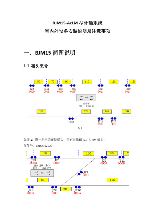
BJM15‐AzLM型计轴系统室内外设备安装说明及注意事项一. B JM15简图说明1.1磁头型号图1如图1:图中所示为正线磁头,所有正线磁头均为4M磁头,部件号:82001 02025图2图3图2、图3所示分别为侧线磁头和交叉渡线磁头,此类非正线的磁头均为8M磁头,部件号:82001 020301.2共用磁头图4图4中所示的为共用磁头标记,长箭头表示供电方、短箭头表示共用方。
二.室外安装注意事项2.1 EAK安装注意事项2.1.1 ZP30H安装位置总则1.EAK原则上只允许安装在外侧钢轨一边;2.磁头电缆不允许扭绞、盘圈、截短;3.图纸上方所示路线的EAK面板应始终正对计轴参考方向;4.图纸下方所示路线的EAK面板应始终背对计轴参考方向;5.正线所使用的磁头电缆均为4米;6.非正线所使用的磁头电缆均为8米。
2.1.2 EAK安装位置细则正线的磁头线均为4米图5如图5所示:7.当磁头安装在图纸上方所示路线时,以磁头为基准,EAK应安装在沿计轴参考方向推移约2米的位置上;8.图纸上方所示路线的EAK面板(4根磁头电缆进线口一面)应始终正对计轴参考方向;9.当磁头安装在图纸下方所示路线时,以磁头为基准,EAK应安装在沿计轴参考方向推移约2米的位置上。
10.图纸下方所示路线的EAK面板(4根磁头电缆进线口一面)应始终背对计轴参考方向;非正线处的磁头线均为8米如图6、7所示:图6图7高架部分:如图8所示:图81.当磁头安装在图纸上方所示路线时,以磁头为基准,EAK应安装在沿计轴参考方向推移约2米的位置上;2.图纸上方所示路线的EAK面板(4根磁头电缆进线口一面)应始终背对计轴参考方向;3.当磁头安装在图纸下方所示路线时,以磁头为基准,EAK应安装在沿计轴参考方向推移约2米的位置上。
4.图纸下方所示路线的EAK面板(4根磁头电缆进线口一面)应始终正对计轴参考方向;2.2钻孔定位的设置原则1.钻孔位置距钢轨接头不小于1m;2.相邻的两个计轴点间不小于2m;3. 钻孔位置距旁边钢轨的距离不小于1m;4.应安装在两根枕木中间的钢轨上,且应避开轨距杆等金属器件,并注意两根枕木之间的距离应不小于400mm,如果需要安装的轨腰上有凸出字体,需磨平或者换地方打孔。
AzLM型计轴系统维护手册
AzLM型计轴系统维护手册(V2.0)北京泰雷兹交通自动化控制系统有限公司 Thales Transport Automation Control Systems Co.,Ltd.,Beijing2010年9月北京泰雷兹交通自动化控制系统有限公司Contents/目录/介绍 (1)1 INTRODUCTION1.1 Scope / 范围 (1)1.2 Intended Audience /相关人员 (1)1.3 Abbreviations /缩写 (1)2 SAFETY RELEVANT APPLICATION RULES /安全相关应用规则 (2)2.1 Applications / 应用 (2)2.2 Test equipment /测试设备 (2)2.3 List of test equipment /测试设备列表 (2)2.4 Periodical counting tests at the Detection points /在检测点进行的周期性计数测试 (3)2.5 Insulation to Ground /对地绝缘 (3)2.6 Storage Conditions/储存条件 (3)2.7 Using the Diagnostic PC /诊断机的使用 (3)2.8 Installation and maintenance of detection points /检测点的安装和维护 (4)2.9 Vehicles with non-standard wheels /非标准车轮的车辆 (5)2.10 Holding spare parts /备件的保存 (5)/人员安全 (5)3 PERSONALSAFETY3.1 Zp30H (5)3.2 ACE (5)4 GENERAL ASPECTS OF THE ACE/ ACE的一般特性 (6)4.1 Restart of ACE / ACE的重启 (6)5 CHANGING BOARDS /更换电路板 (6)6 CHANGING SOFTWARE /更换软件 (7)7 SPARE PARTS /备件 (8)8 AXLE COUNTER RESET /计轴复零 (8)9 INSPECTION/检查 (8)9.1 ACE/ACE (8)9.1.1 ACE (8)9.2 Inspection Zp30H /检查Zp30H (9)9.2.1 Measurement at the ACE /ACE的测量 (9)9.2.2 Visual checks /外观检查 (9)9.2.2.1 General condition of the detection point /检测点通常状态 (9)Clearance of transmitter head /发送磁头的间距 (10)9.2.3 Zp30H Log Sheet for Inspection / Zp30H的检查记录 (10)10 DISPOSAL /处理 (11)北京泰雷兹交通自动化控制系统有限公司1 INTRODUCTION /介绍1.1 Scope / 范围This document is a maintenance guideline for AzLM covering the following topics:该文档是AzLM维护手册,包括以下内容:• General aspects of maintenance such as handling of spares维护的主要方面,例如备件的处理• Safety relevant aspects of maintenance and operations including the axle counter reset维护和运营的安全相关方面,包括计轴复零• Inspection检查Fault finding is not covered by this document. It is dealt with in AzLM Operating Instruction.本文档不包括故障发现,故障发现在AzLM操作手册中解决。
Xalz参考手册李

MarcoXalz电液控制软件用户参考手册编篡:北京天地玛珂电液控制系统有限公司二00一.十目录一对话框入门 (6)二服务对话框 (12)三设置对话框 (22)四控制对话框 (32)五诊断对话框 (55)六统计对话框 (65)七图形对话框 (69)八SCU对话框 (79)九帮助对话框 (90)十图形界面的对话框 (93)十一术语解释 (101)一对话框入门目录1. 激活开采方式2. 启动开采方式3. 执行功能4. 手动推溜5. 图形管理1. 激活开采方式打开对话框通过点击主窗口“控制”区,“控制”栏下,显示(“---”,“增量”“增量+自动移架”)的按钮,打开本对话框。
对话框窗口图对话框功能激活的开采方式在对话框上部显示。
当选择“增量”开采方式时,可以移动基线,并可打开或关闭基线自动移进,而且可以停止当前激活的开采方法或者在帮助提示下选择新方法。
对话框说明开采方式显示激话的开采方式,模式可在另一个对话框中改变(点击“选择”按钮)。
如果没有激活的开采方法,显示“---”。
基线按下标有方向键头按钮可以前移或后移基线位置,向上键头表示前移,向下键头表示后移。
单键头表示每按一下移进一步。
双键头表示移动10倍移动步距。
从机头到机尾可以设置不同的步进距,通过手工干预,这个步距决定于当前位置和基线位置,系统认为采煤机将朝更大面部分的方向移动。
如果选择传统模式,基线设置是无效的。
自动移进这里可以打开或关闭基线的自动移进,如果打开,基线将自动前移。
开采方式这里可以按下“停止”按钮停止开采方法,“选择”按钮选择新的开采方法。
清除运行当方式是“增量”或“增量+自动移架”时,这里可以调整采煤机是否做清除运行。
打开按下进行清除运行,当前采煤机运行时不推溜。
关闭关闭清除运行,采煤机运行时正常推溜。
2.启动开采方式打开对话框如果在上述对话中选中“选择”按钮,弹出本对话框。
对话框窗口图对话框功能在此对话框中,可以开始预期的自动模式。
TAZ II计轴设备调试手册V1.1

纠偏安装调试说明
安装调试注意事项及步骤:
1、控制盒外壳、电眼外壳要接地线,该地线截面达到4平方mm;
2、马达安装要水平且转子部分和螺杆部分的直线度要好,马达线接线要用屏蔽线且与高压线分开走,以免被干扰;
3、电源电压要稳定,达到24V,如果机器开动后这个电压出现降低的话,则纠偏器要使用独立的24V电源供电,以确保稳定新,因为电压不够会减小马达的推力从而使被卡住,推不动机台;
4、近接开关安装在机台滑动的中心,且要靠近感应铁块,该铁块的长度要达到超过马达行程的一半,铁片的边缘也要安装在中心位置,近接开关线要跟高压线分开不然容易被干扰;
5、初始化之前先达到对中模式;
6、先开锁3—42,然后改参数25、34、35、36、48、50、51、5
7、62、63,这些参数要在初始化之前调整好,不同的马达这几个参数的设定值是不一样的,可以通过马达上标签查型号和料号从而确定这几个参数值;
7、执行3—10初始化,完成后看看电路板上的LED灯是否有错误报警,然后调整26、27(正负行程)、30、31、32参数;
8、然后测试手动、自动、归中各种模式的动作是否正常。
AzLM型计轴系统操作手册
AzLM型计轴系统操作手册(V2.0)北京泰雷兹交通自动化控制系统有限公司Thales Transport Automation Control Systems Co.,Ltd.,Beijing2010年9月北京泰雷兹交通自动化控制系统有限公司Contents/目录1 INTRODUCTION/介绍 (1)1.1 Overview /概述 (1)1.2 Intended Audience /目标用户 (1)1.3 Abbreviations/缩写 (1)1.4 General information/一般信息 (3)2 LED INDICATIONS/发光二极管表示含义 (3)2.1 ACE/ACE (3)2.1.1 Serial I/O for 2oo2 /串口板 (3)2.1.3 Parallel I/O/并口板 (4)2.1.4 CPU/中央处理器 (5)2.1.5 Power Supply/电源板 (7)2.2 Detection Point/检测点 (8)2.3 PDCU (9)北京泰雷兹交通自动化控制系统有限公司1 INTRODUCTION/介绍1.1 Overview /概述The following aspects are covered by this document:该文档包括以下几个方面:• Diagnostic and test equipment诊断和测试设备• Connecting the PC与PC相连接• Characteristics of the diagnostics诊断特性• Fault finding故障查找1.2 Intended Audience /目标用户•Commissioners 调试人员•Maintainers 维护人员•Tester 测试人员1.3 Abbreviations/缩写北京泰雷兹交通自动化控制系统有限公司北京泰雷兹交通自动化控制系统有限公司1.4 General information/一般信息•The operational railway safety regulations must be observed during all phases of operation of the equipment.设备运营的所有阶段必须符合相关铁路安全规定。
AzLM型计轴远程诊断系统
t e m i n ie f l d o p e r a t i o n ,we d e v e l o p e d a k i n d o f r e mo t e d i a g n o s i s t e c h n i q u e.Th i s t e c h n i q u e c a n b e u s e d t o p r e v e n t t he p o t e n t i a l f a i l u r e i n a d v a n c e a n d p e r f o r m f a s t r e mo t e d i a g n o s i s i n t h e c a s e o f f a i l u r e,wh i c h c a n s ho r t e n t he l a s t i n g t i me o f f a i l u r e s a n d i mp r o v e t h e s a f e t y o f t h e ma c h i n e a c c o r d i n g l y .
2 0 1 3年 1 0月
铁 道 通 信 信 号
RAI L W AY S I GNAL L I NG & C 0MMU NI C AT 1 0N
0c t o b e r 201 3
第4 9卷
第1 O期
Vo 1 . 4 9 No . 1 0
A z L M 型计 轴 远 程 诊 断系统
科研项 目:安康电务段科研项 目 收 稿 日期 :2ຫໍສະໝຸດ 0 1 3 - 0 6 - 2 7
一
2 3—
铁道通信信号 2 0 1 3 年第 4 9 卷第 1 O 期
3 方 案 实 施
AZ产品操作和维护说明书
ARMATUREN1Storage, operating andmaintenance instructionsfor AZ plug valves andStandard valves Plug - Valves metallic with PTFE Sleeve 2 - 7 way Plug - Valves FEP/PFA - lined, 2 - 3 wayButterfly - ValvesFEP/PFA - linedBall - ValvesFEP/PFA - linedBallcheck - Valves metallicwith FEP/PFA - linedSampling - Systems forliquid, liquid gas and gasSpecial - Valvesand customizedContent :1. General information2. Marking3. Safety instructions4. Transport and storage5. Installation and start-upa) Mounting Instructionb) Statement on Directives 2014/68/EU and 2006/42/EGc) Installation in explosive areas (directive 2014/34EU, ATEX)6. Handling and operating mode7. Maintenance instructions8. Trouble shooting of malfunctions and defects9. Valve readjustment10. Pressure tests2ARMATUREN 31. General informationThese storage, operating and maintenance instructions apply for all AZ plug valves and other AZ products based on the plug valve design. AZvalves are high performance valves which can also be used under extreme conditions. Due to this, the valves should be handled carefully in order to avoid damages which could be hazardous to human health and/or the environment. Please consider the relevant remarks in this manual. Please check the valves immediately after receipt for any defects or transport damages. Claims for transport damages can only be accepted if the forwarder is informed immediately in writing. For return shipments (transport damage or valve repair) please issue a damage report immedi-ately and return the components back to the manufacturer, if possible in the original packaging. Returning shall be sent free of charge for AZ. Other returning terms have to be agreed with the AZ sales department.Please provide the following information as a minimum for the returned valves: • Name and address of the consignee• Order number or AZ reference number• Type of valve• Description of the defectThe valve guarantee period must be agreed and confirmed by AZ at the order confirmation stage. If no agreement has been reached be -tween the buyer and the seller, the standard guarantee period as per our general sales terms and conditions must be applied. In any case, the general warranty terms of AZ Armaturen GmbH always apply. We assume no liability if our storage, operating and maintenance instruc-tions have been ignored and /or used for inappropriate installation or maintenance work. The end user is responsible for the materials selection regarding media consistency. AZ Armaturen can provide ad-ditional technical information such as material recommendations from steel suppliers and references. However, AZ Armaturen doesn’t give any warranty regarding material adequacy and resistance.42. MarkingAccording to EN 19 every valve is marked with the following data:A Charge numberB Tag plateCPart number DNominal pressure [PN]EManufacturer’s sign FMaterial number GNominal diameter [DN] Valves which are covered by the pressure equipment directive 2014/68/EU (> DN 25 / 1”) are additionally marked with a non-removable CE-identification tag plate. This tag plate also includes the test centre identification number, the fitting serial numberalong with its coded year of manufacture (the first two digits stand for the year of manufacture) and the permissible operating condi-tions (T min , T max , P max ):ARMATUREN3. Safety instructionsAZ valves are high quality products manufactured accordingto the latest applicable technical regulations, and have leftthe manufacturer´s workshop in perfect condition. Installation,adjustment, maintenance and repair work of valves, pneumaticaccessories and electrical equipment shall only be executedby correctly trained and authorized personnel. AZ ArmaturenGMBH accepts no liability for damage caused by unauthorizedmodification of any item and/or the use of non-genuine AZspare parts.National legislation for accident prevention and/orthe site specific advice of the end user must alwaysbe considered. This manual is in no way intended toreplace these regulations.Before starting any repair or maintenance work, actuators andelectrical parts have to be de-energized. Please consider a safedistance to open mounted and moving parts in order to avoid in-jury. Ensure that the valves are utilized only within the permittedlimits (especially pressure and temperature). Information aboutthese limits can be found in the technical information leaflet ofthe valves or on the valve tag plate. Operation of valves beyondthe permitted temperature and pressure limits can cause dam-age to the valve, especially on gaskets and components.Valves may only be used for the purpose that they have beendesigned for.56IMPORTANT NOTE:Never carry out any maintenance or repair work if the valve is under pressure. Please consider that some valves can trap pressurized medium (e.g. in the plug of the plug valve). IMPORTANT NOTE: The piping system where the valve is installed has to be pressure-free and any media over pressure has to be released before dismounting. Check potential risks which can be caused by media residues. Please consider that media can be released from the valve or piping during dismounting.In case of toxic / dangerous / harmful media, the pipe has to be emptied completely before dismantling the valve. Hot valves must be cooled down to ambient temperature before work starts.For your own safety, please always use the correct protective clothing or special equipment which is required for work with a particular media.4. Transport and storage AZ valves must be stored in fully open position. In certain cases (actuated valves with fail safe position “closed”), the valves can be stored in closed position, but storage in a half open position has to be avoided at all times. AZ valves are delivered with the end connections covered by protection caps. These caps protectARMATUREN the valve ends from mechanical damage and the internals fromenvironmental influences (e. g. dust, dirt etc.). The protectivecaps shall only be removed when the valve is to be installed. Thevalves shall be stored indoors in order to protect them from de-structive influences like dirt, moisture and frost. The valves shallbe transported in solid and stable packaging to the place of instal-lation. Lifting accessories (ropes, belts) shall only be attached tothe valve bodies. Never use the levers, gear boxes or actuators tolift the valves.IMPORTANT NOTE: Valves which have been in-stalled in toxic or aggressive media applicationsmust be flushed and cleaned before returningthem to the supplier for repair or disposal. Mediamay be located underneath the plug so the valvemust be disassembled, the plug removed and allindividual parts must be provided fully cleaned. Acertificate of non-objection and a material safetydata sheet must be attached to the shippingdocuments and shall be included in the delivery.5. Mounting Instruction and start-upa) Mounting InstructionImportant Note: This does not apply for check valves, controlvalves and sight glasses. These valves are marked with an arrowindicating the flow direction. Valves which areequipped with a plug with relief hole or a “T4”-plug, a notch on the plug stem indicates theorientation of the overpressure relief side.Obey Flow direction(Sight glasses a.s.o.)7In order to avoid valve damage caused by line impurities (swarf-, dirt,welding residues) the pipeline must be emptied and cleaned beforeinstallation of the valves. Prior to installation, ensure that the valve is in open position and the valve end protection caps are removed. Checkthe sealing surface of flanged valves for damage. In case the valve has been stored without protection caps, please make sure that the valve is clean inside. If necessary flush the valve with clean and dry air.The valves must be installed stress-free in the pipeline. For example,stress can occur due to misaligned pipelines. Place the valve in thepiping, if needed, by using lifting accessories. Flanges shall be boltedconstantly crosswise. Please consider the stipulated fastening torque of the gasket manufacturer. Flanges and bolting should be clean. A flange gasket which is suitable for the application shall be used. Please en-sure that the valves are properly supported during installation. Normally the valves can be installed in any position. However, please considera support / bearing for heavy actuators if the valve is mounted in avertical pipe or the actuator orientation is not on top of the valve / piping (sideways).In order to protect the valve’s internal sealing fromoverheating, please make sure that there is suffi-cient cooling if the valve is welded into the pipe-line (butt weld / socket weld end valves).Please check the whole valve for proper operation by repeatedopening and closing before commissioning (<2 strokes per min-ute). In case of prolonged storage of the valve the breakawaytorque during the first stroke may be higher than usual, after fre-quent operation the torque will reduce to the normal level.Please check if the hand lever or the actuator is installed in sucha manner that the valve closes clockwise. When installing multiway valves (three-way, four-way etc.) please check the port formand the switching positions in order to avoid incorrect connectionto the piping. The switching positions are shown on the position8ARMATUREN 9indicator (hand operated valves) or by red marks on the coupling (actuated valves). Please finish all installation work before putting the valves into operation. RECOMMENDATION: If the operat-ing temperature exceeds 150°C the plug may be adjusted once operating temperature has been reached (1/2 to 1/1 turn of the adjustment bolt).b) Statement on Directives 2014/68/EU and 2006/42/EGAZ valves are pressurised equipment components according to the Pressure Equipment Directive 2014/68/EU. The design, manu-facture, and testing of the valves comply with the requirements of this directive. On the basis of its prescribed use with its installed pneumatic, electric, or hydraulic drive, AZ-Armaturen are classi-fied as “incomplete machinery” within the meaning of Machinery Directive 2006/42/EG.On the basis of their intended use, AZvalves, with installed pneumatic, electric or hydraulic drives, are considered “incomplete machinery” according to the Machinery Directive 2006/42/EG. The valves must be used exclusively in the same way that their specifications are described in this operating manual. The automated valve may only be commissioned after the pipeline has fully been installed.c) Installation in explosive areas (directive 2014/34/EU (ATEX)AZ valves has undergone a hazard analysis according to directive 2014/34/EU (ATEX). Result:• According to DIN EN 13463-1:2000 AZ-valves don’t have anown potential ignition source and therefore they are not cov-ered by the scope of application of code 2014/34/EU (ATEX).• There’s no marking according to ATEX.• All valves can be used in explosive areas ( zone 0,1,2 and20,21,22).IMPORTANT NOTE:• Fully lined valves which are installed in zone 0 and 20 have to be lined with conductive PFA material. A static eliminator devicehas to be assembled in order to connect the plug with the body(grounding).• AZ valves can be operated manually (e.g. hand lever, gear box) as well as mechanical or electrical (e.g. pneumatic, hydraulic orelectric actuator).• For electrical and mechanical actuators and accessories an own declaration of conformity according to code 2014/34/EU mayhave to be considered.• Whenever fully lined valves with non-conductive lining are in-stalled in explosive areas, AZ-Armaturen GmbH strongly rec-ommends the use of an anti-static band/earth cable in order toensure grounding of the plug.6. 6. Operation and functionalityBall and plug valves are installed in pipeline systems byflanging, screwing or welding and are designed to conduct,block or control media flow. On/off valves have the open andclosed position indicated by the lever position (lever longitu-dinal to the valve = open, lever perpendicular to the valve =closed) or by a position indicator on top of the gear box. Flow directions of multiport valves are indicated by a notch on theplug stem or by a position indicator assembled on top of theplug or the gear box. Flow directions of actuated valves areindicated by red markings on the coupling between valve and actuator.Jacketed valves are used for particular media in order tomaintain the process capability or the flow.10ARMATUREN Control valves are used for the adjustment and the relocationof a certain process factor (mass flow, pressure, temperature).With sampling valves and sample systems representativesamples are taken during the ongoing process out of chemi-cal, petrochemical and pharmaceutical systems in order tomonitor and control the media quality.A sight glass with optical transparent glass can be usedfor observing process flow. A strainer protects dirt sensitiveinstallations as measurement devices or pumps from line im-purities7. Maintenance instructionsUnder normal conditions and in the case of the use accordingto the regulations, frequent maintenance work on AZ valves isnot necessary. After an extended period of operation, AZ recom-mends checking the function of the valve by repeated open-closestrokes. Tightness of the valve/pipe connection and valve coverarea may also be visually checked for leakage. The functionalityof valves which remain constantly in the same position should bechecked frequently, e. g. by performing a “partial-stroke-test”.After a certain operating time, leakage can occur due to wear-ing of the sealing parts, small leakages (depending on type ofsealing) can be stopped by tightness adjustment (please refer topages 7 + 8).After finishing maintenance or repair work please check theproper function of the valve (particularly the closing position ofactuated valves) and the tightness of the connection betweenvalve and piping.118. Malfunction / defects and fault clearance Malfunc-tionPossible reason Fault clearanceLeakage in the pas-sageway • The allowed valve operatinglimits (pressure / tempera-ture) have been exceeded.• Damage of the sleeve orplug resp. ball surfacecaused by foreign particles.• Wearing of the sleeve.• Damage of the valve due tochemical corrosion, causedby wrong material selectionregarding media suitability.• Check if the valvecloses completely.• Adjustment of theplug according to theguideline (please referto pages 13 + 14).• If the leakage cannotbe stopped the valvehas to be repaired.External leakage (cover or stem seal)• The allowed valve operatinglimits (pressure / tempera-ture) have been exceeded.• Wearing of the sleeve.• Damage of the valve due tochemical corrosion, causedby wrong material selectionregarding media suitability.• Cover bolting became loose(e.g. caused by heavy vibra-tions in the pipeline)• Wearing resp. damage of thecover seal.• Adjustment of theplug according to theguideline (please referto pages 13 + 14).• Check if the coverbolting is fastenedproperly.• If the leakage cannotbe stopped the valvehas to be repaired.High torque/ valve blocks • Possible change of the me-dia aggregate state.• Deposit of media on plugresp. ball surface.• Solid media or forgotteninstallation devices in thevalve• Remove deposits andsolid media.Malfunction of actuator or acces-sories See corresponding guidelines / manuals of the manufacturer.12ARMATUREN9. Adjusting instructionsAdjusting instructions in case of leakage for AZ plug valves type: ISO-STANDARD DN15-100 NPS ½“-4“ / ISO-EXTRA DN15-80 NPS ½“-3“1. Plug should be in an open position2. Both adjusting bolts shall be turned ¼ to ½ rotations clock-wise one after another.3. Afterwards move the plug 10-15 degrees and back.4. If the valve is still leaking please repeat step 2) and 3).Please do not over tighten the adjustment bolts as the breakaway torque may increase beyond the normal limits.Adjusting screws (plug)Thrust collar Stainless diaphragm with delta thrust collar PTFEsealing ring PTFE sleevePlug14Adjusting instructions in case of leakage for AZ plug valves type: STANDARD DN125-600 NPS 5“-24“ / EXTRA DN100-600 NPS 4“-24“1. Plug should be in an open position2. All adjusting bolts shall be turned ½ to 1/1 rotations clockwise oneafter another.3. Move the plug 10-15 degrees and back.4. If the valve is still leaking please repeat step 2) and 3).NOTE: Please do not over tighten the adjustment bolts as the breakaway torque may increase beyond the normal limits.Plug Adjust-ing screwsThrust collar thrust collar Diaphragm sealing PlugPTFE sleeveNOTE: Special cover sealing designs (e. g. type “FS-N”) may vary.diaphragmARMATUREN10. Pressure testsIn accordance with ISO 5208 / EN 12266 and API 6D / API 598 hydros-tatic strength tests using 1.5 times the nominal pressure (housing) arecarried out at the factory. The complete valves are either tested hydrosta-tically using the indicated valve nominal pressure or an air tightness testusing 6 bar is carried out.For system specific pressure tests carried out by the operator the nomi-nal pressure must not exceed 1.1 times of the value specified on the typeplate (also refer to section 2 “Marking”). For test pressures higher than“1.1 x PN” there is the risk of damage to the PTFE (polytetrafluorethyle-ne) seal. Higher pressure tests only after authorisation by AZ.*) Tightness test of the valve at closure**) Tightness test of the outward valve15ARMATURENP r i n t 03/2017 - R e v 3 - G B - S u b j e c t t o t e c h n i c a l c h a n g e w i t h o u t n o t i c eAZ-Armaturen GmbH Waldstraße 7D-78087 MönchweilerTelefon: +49 (0) 7721 7504-0Telefax: +49 (0) 7721 7504-13********************www.az-armaturen.de。
AzLM型计轴系统操作手册
AzLM型计轴系统操作手册(V2.0)北京泰雷兹交通自动化控制系统有限公司Thales Transport Automation Control Systems Co.,Ltd.,Beijing2010年9月北京泰雷兹交通自动化控制系统有限公司Contents/目录1 INTRODUCTION/介绍 (1)1.1 Overview /概述 (1)1.2 Intended Audience /目标用户 (1)1.3 Abbreviations/缩写 (1)1.4 General information/一般信息 (3)2 LED INDICATIONS/发光二极管表示含义 (3)2.1 ACE/ACE (3)2.1.1 Serial I/O for 2oo2 /串口板 (3)2.1.3 Parallel I/O/并口板 (4)2.1.4 CPU/中央处理器 (5)2.1.5 Power Supply/电源板 (7)2.2 Detection Point/检测点 (8)2.3 PDCU (9)北京泰雷兹交通自动化控制系统有限公司1 INTRODUCTION/介绍1.1 Overview /概述The following aspects are covered by this document:该文档包括以下几个方面:• Diagnostic and test equipment诊断和测试设备• Connecting the PC与PC相连接• Characteristics of the diagnostics诊断特性• Fault finding故障查找1.2 Intended Audience /目标用户•Commissioners 调试人员•Maintainers 维护人员•Tester 测试人员1.3 Abbreviations/缩写北京泰雷兹交通自动化控制系统有限公司北京泰雷兹交通自动化控制系统有限公司1.4 General information/一般信息•The operational railway safety regulations must be observed during all phases of operation of the equipment.设备运营的所有阶段必须符合相关铁路安全规定。
IZML HART安装包说明书
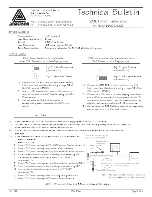
HART board hardware for installation to an IZML flowmeter with Non-Display coverQty: 2 - M6 x 10mm screws(Included in kit)Qty: 2 - 6mm Flat Washer1.) Remove the CS3-BUS terminal block from the IZMLMain board (see Main board drawing on page 20 of the IZML manual AIC2041).2.) Fasten HART transmitter board to IZML convertercover at the lower standoff location using two M6 x 10mm screws.3.) Connect prewired CS3-BUS connector tocorresponding socket located on the IZML main board.Anderson Instrument Co., Inc.156 Auriesville Rd.Fultonville, NY 12072Phone: 518-922-5315 or 800-833-0081Fax: 518-922-8997 or 800-726-6733Technical BulletinIZML HART InstallationKit P art# 56704A0001Rev. 1.0P age 1 of 2Doc 1153SPECIFICATIONSCommunication:HART version 6 Loop P ower (excitation): 24 vdcOutput: 4-20mA dc, 2-wireLoop Resistance: 500 ohms (max) at 24 vdcCable Recommended:2 conductor; stranded, 18-24 AWG, shielded with groundINSTALLATIONZero Trim1.) Apply loop power to the HART transmitter board after applying power to the IZML converter.2.) Connect the HART communication device across the transmitter terminals. The signal loop must have at least 250 ohms resistance for HART communication device function.3.) Turn on the HART communication device. Wait until communications are established and the Home Menu is displayed.4.)If the Process Value is not within specification after stabilization:1. Select Calibration2. Select D/A trim3. Select “OK” to acknowledge WARN-LOOP remove from auto control4. Select “OK” to acknowledge connection of mA indicator5. Select “OK” to acknowledge setting field deviation output to 4mA.6. Enter indicated mA value and acknowledge with selecting “OK”7. Acknowledge indicated mA adjustment with “YES/NO” then select “OK”8. Select “OK” to acknowledge setting field deviation output to 20mA.9. Enter indicated mA value and acknowledge with selecting “OK”10. Acknowledge indicated mA adjustment with “YES/NO” then select “OK11. Select “OK” to acknowledge loop returning to original output12. Select “OK” to acknowledge NOTE return to auto controlNOTE: HART output will fault at 3.85mA with loss of IZML signal.IZML HART Transmitter BoardP art Number 56014E0137Secure groundHART board hardware for installation to anIZML flowmeter with Display coverQty: 2 - Nylon Spacers(Included in kit)Qty: 2 - M6 x 16mm screws(Included in kit)1.) Remove the CS3-BUS terminal block from the IZMLMain board (see Main board drawing on page 20 of the IZML manual AIC2041).2.) Replace both IZML converter cover display board lowerstand off mount screws with nylon spacer, then HART transmitter circuit board, then lock washers from the original mount screw, and two M6 x 16 mm screws.3.) Connect prewired CS3-BUS connector to correspondingsocket located on the IZML main board.NOTE: Disconnecting the CS-3 terminal while operating the flowmeter will cause temporary lose of measurement.Input/Output Setup CalibrationMeter InfoHART Info UnitsMeter OutputRangingPulse OutputsDigital Input DebounceFlow Rate UnitsQ-TypUnitsmdimCurrent ModeMeter Out Damp(Tp3)PV URVUSLLSLAverageDampingVminLFSOutput Modepv1Tp1pv2tp2it1it2it3it4SpanOffsetm.spep.spen.speb.speD/A TrimLoop TestDac ZeroDac FullDNPipe DetectStandby ModeParameter ModeSwitch Position Factory Cal ParametersSystem Cal ParametersLoop Current CalMeter SetupDisplay SetupMeter VersionsChecksumsFixed InfoUser InfoRevision DataV1 FormatV2 FormatDecimal Pt.Display ModeUser C2:System SS:Appli SA:erpsumeparasumnparasumManufacturerModelDev idNum req preamsMessageTagDescriptorDatePoll addrFinal assembly numUniversal revFld dev revSoftware revHardware revIZM HART FlowchartRev. 1.0P age 2 of 2Doc 1153。
AzLM型计轴系统工程手册[V1.1]
![AzLM型计轴系统工程手册[V1.1]](https://img.taocdn.com/s3/m/5b4fb68185868762caaedd3383c4bb4cf7ecb711.png)
AzLM型计轴系统工程手册(V1.1)阿尔卡特交通自动化控制系统XXAlcatel Transport Automation Control System Co.,Ltd.,Beijing2008年3月目录1 简介12 规划原则12.1 应用12.2 系统局限12.2.1 每个ACE的检测点数量12.2.2 每个ACE的区段数量12.2.3 每个检测点的区段数量12.2.4 区段长度12.3 计轴参考方向22.4 轨道配置举例32.4.1 直线区段32.4.2 复杂轨道配置32.4.3 关联道岔组32.4.4 重叠区段32.5 检测点位置32.6 从AzLM向其他列车检测设备转换33 工程33.1 前提条件33.2 配置ACE43.2.1 硬件模块化43.2.2 联锁接口53.2.3 数据准备63.3 检测点配置63.4 连接63.4.1 概述63.4.2 电源73.5 ACE和ZP30H接线73.5.1 ACE-2-X:通过数据线给ZP30H供电73.5.2 ZP30H供电方案 (15)3.5.3 ZP30H的多重应用 (16)3.5.4 使用ISDN/V.24转换器 (18)3.5.5 使用线路变压器 (20)3.6 接地83.6.1 轨旁设备83.6.2 室内设备93.7 轨旁电缆布线93.7.1 总则93.7.2 电线要求93.7.3 对称93.7.4 电缆网络93.7.5 合适的电缆93.7.6 轨旁电缆布线的感应电压103.7.7 电缆屏蔽103.7.8 和铜电缆其他服务的兼容性10 3.8 电源103.8.1 计轴评估器ACE103.8.2 检测点ZP30H103.9 ZP30H的使用X围113.9.1 星型四线扭绞电缆计算举例111 简介AzLM系统是阿尔卡特公司近几年在世界最新计算机技术、通信技术和传感器技术基础上开发的新型计轴系统,其技术和工艺引领世界先进水平。
该系统由室内ACE主机和室外轨旁计轴点设备组成。
泰雷兹AzLM-ZP30H计轴系统接口原理及故障分析
• 134•广州地铁二十一号线采用泰雷兹AzLM-ZP30H 计轴定位系统。
本文介绍该计轴系统的结构组成、基本原理、和联锁计算机的接口采集以及故障状态,并结合分析为计轴系统接口故障提出排查建议。
1 计轴概况在泰雷兹CBTC 信号系统中,正常情况下轨旁与列车定位通信是基于无线传输技术,当无线通信传输失效时次级定位可利用轨旁计轴区段的占用状态来确定列车位置。
其基础原理为比较列车驶入和驶出所监视轨道区段的轮对轴数并以此确定该区段的占用或空闲状态,当轮对轴数对比不一致时则显示为受扰状态。
计轴系统与联锁系统存在一定的接口关系,以广州地铁二十一号线为例,采用的是泰雷兹AzLM-ZP30H 计轴系统,该计轴系统与联锁之间存在两种接口关系以适应正线和车辆段不同的应用场景。
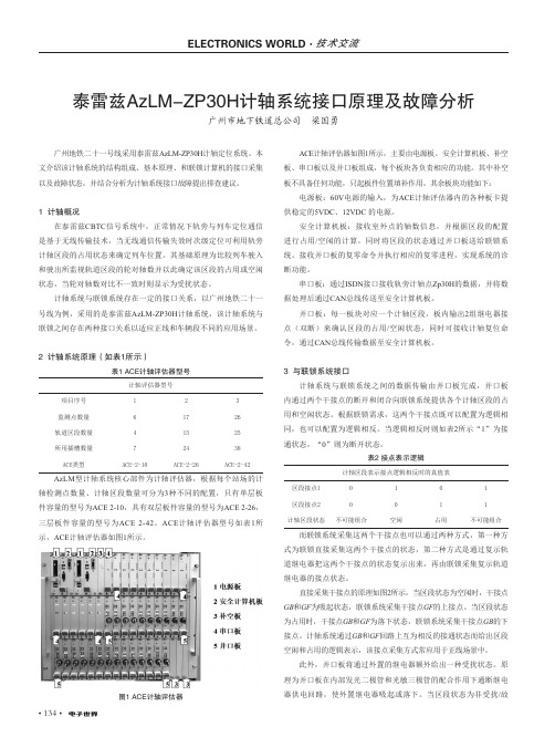
2 计轴系统原理(如表1所示)表1 ACE计轴评估器型号计轴评估器型号项目序号123监测点数量61726轨道区段数量41525所用插槽数量72438ACE类型ACE-2-10ACE-2-26ACE-2-42AzLM 型计轴系统核心部件为计轴评估器,根据每个站场的计轴检测点数量、计轴区段数量可分为3种不同的配置,只有单层板件容量的型号为ACE 2-10,具有双层板件容量的型号为ACE 2-26,三层板件容量的型号为ACE 2-42。
ACE 计轴评估器型号如表1所示,ACE 计轴评估器如图1所示。
图1 ACE计轴评估器ACE 计轴评估器如图1所示,主要由电源板、安全计算机板、补空板、串口板以及并口板组成,每个板块各负责相应的功能。
其中补空板不具备任何功能,只起板件位置填补作用。
其余板块功能如下:电源板:60V 电源的输入,为ACE 计轴评估器内的各种板卡提供稳定的5VDC 、12VDC 的电源。
安全计算机板:接收室外点的轴数信息,并根据区段的配置进行占用/空闲的计算,同时将区段的状态通过并口板送给联锁系统。
接收并口板的复零命令并执行相应的复零进程,实现系统的诊断功能。
小型纵横坐标读数器安装说明书

center of the carriage. Using the bracket as a template, use a transfer punch to mark the hole locations. Using an electric hand drill, drill and tap two ¼-20 NC holes.
Mounting the DRO
Once the brackets are completed, the next step is to mount them on the mini mill. Y-axis Mount Bracket 2 on Bracket 1 using two 8-32 x ½” socket head cap screws. Mount the Y-axis encoder on Bracket 1 using the screws furnished with the DRO.
Bracket 6 ¼ x ¾ x 4”
¼ x ¾ x 4” Aluminum Flat Bar
Bracket 7 1/8 x ¾ x 4” 1/8 x ¾ x 4” Aluminumቤተ መጻሕፍቲ ባይዱFlat Bar
There are drawings of these parts at the end of this document.
Using two ¼-20 x ¾” socket head cap screws, mount Bracket 1 on the left side of the carriage. The top of the bracket should be flush with the top of the
计轴设备安装调试手册
计轴设备安装调试手册(总16页)-CAL-FENGHAI.-(YICAI)-Company One1-CAL-本页仅作为文档封面,使用请直接删除第四章设备的安装调试AZL90-3包括室内ACE与室外EAK30C。
ACE部分,基本上已在工厂组装好,引出电缆亦已配好,工作量不大;主要在室外,在每个测轴点,EAK30C 总是和作为传感器的磁头一起使用,二者合起来称为ZP30C。
ZP30C的安装与调整对整个系统能否稳定工作,极为重要。
1.SK30型磁头的安装1.1工具准备打孔模板一块 17860 8910K开口或套筒扳手开口 19 (磁头用)开口或套筒扳手开口 13 (发送磁头)开口或套筒扳手开口 23 (电缆引入)开口或套筒扳手开口 32 (电缆引入)一把钻,直径12mm1.2磁头安装位置的选择磁头应安装在两个枕木之间的钢轨上,即将两个男子枕木间的中心点作为中间一孔的参考点,安装处还应避开轨距杆和其他越轨金属器件,在遇到护轮轨时,要在相对位置处锯掉1米,尽可能远离钢轨接头(大于1米),主要是考虑到震动影响;复线区段,磁头最好安装在靠外侧的一根钢轨上,以减少积累干扰的影响,另外这样安排对检测EAK的人员来说会比较安全。
安装孔的位置正确与否,非常重要,位置不正确,就不可能正确地调整磁头。
对安装孔的尺寸要求很严,不同的轨型,其相应的打孔尺寸也不同,三个安装孔的尺寸规定如下(见图26)其中:a=(*h)-6mm 公差为±1mmh=钢轨高度(指新钢轨)b=13mm±c=148mm±经过计算a与h的对应值列于下表轨高*我国铁路正线上使用的43kg/m轨型,h为140mm,50kg/m轨型,h为152mm,60kg/m轨型,h为176mm。
实际操作时:打孔方向应从外侧打向内侧:把打孔模板装在钢轨的轨底,调节模板的高度,调到已选定的a值,然后用钢冲标出第一、第二两个孔的位置,打好孔后,再把模板加上,定出第三个孔的位置,打完孔后,去掉钻孔上的毛口,并用钢刷把轨腰清理干净。
AZLM-ZP30H计轴资料
AzLM 型计轴系统
维护手册
(V2.0)
北京泰雷兹交通自动化控制系统有限公司
版本和签发记录
《AzLM 型计轴系统维护手册》 (V2.0)
版本
日期
编辑
校对
审批
改版原因
V2.0 2013 年 7 月
版本更新
目录
引言 ................................................................................................................................. 1 1 AzLM 计轴系统组成介绍 ............................................................................................. 2
3 AzLM 型计轴系统维护工具 ....................................................................................... 16 3.1 GDI 诊断系统.............................................................................................................. 16 3.1.1 概述 ....................................................................................................................... 16 3.1.2 创建一个新的 ACE .............................................................................................. 16 3.1.3 连接一个 ACE ...................................................................................................... 17
- 1、下载文档前请自行甄别文档内容的完整性,平台不提供额外的编辑、内容补充、找答案等附加服务。
- 2、"仅部分预览"的文档,不可在线预览部分如存在完整性等问题,可反馈申请退款(可完整预览的文档不适用该条件!)。
- 3、如文档侵犯您的权益,请联系客服反馈,我们会尽快为您处理(人工客服工作时间:9:00-18:30)。
AzLM型计轴系统
安装调试手册
(V1.1)
北京泰雷兹交通自动化控制系统有限公司
Thales Transport Automation Control System Co.,Ltd.,Beijing
2008年11月
目录
1简介 (1)
2安装 (1)
2.1先决条件 (1)
2.1.1文档 (1)
2.2安装ZP30H和电缆 (2)
2.3安装ACE (2)
2.4安装PDCU (2)
2.5安装ISDN/V.24转换器 (3)
3调试 (3)
3.1先决条件 (3)
3.2 测试 (3)
3.2.1软件版本检查 (4)
3.2.2数据检查 (4)
3.2.3对应测试 (4)
3.2.4与其他轨道检测系统的分界 (4)
1简介
AzLM系统是泰雷兹公司近几年在世界最新计算机技术、通信技术和传感器技术基础上开发的新型计轴系统,其技术和工艺引领世界先进水平。
该系统由室内ACE主机和室外轨旁计轴点设备组成。
轨旁计轴点设备包括SK30H轨道磁头传感器和ZP30H电子盒。
室内主机与室外计轴点之间采用ISDN数据线进行通信,且电源与通信可以共线传输。
每台主机最多可以检测32个计轴点、监控32个区段,适用于一般区段和复杂站场。
本文档用于AzLM计轴系统的安装和调试指导。
2安装
2.1先决条件
安装和调试必须经过专门培训。
进行调试时,必须遵守铁路特殊规定和安全规则。
只有零件列表中发布的组件可以使用。
在轨旁工作时需要额外预防措施来确保安全(见ZP30H检测点安装手册)。
2.1.1文档
规划文档
∙现场信号点规划(信号机、道岔、检测点等位置)
∙电缆规划(电缆列表、电缆类型和所使用的电缆)
∙所有计轴轨道区段列表
∙接地概念
∙接地列表
∙电缆感应电压的计算,以及减少感应电压措施列表
工程文档:
∙计轴总体规划包括:
轨道区段、检测点、计轴参考方向
∙计轴定义表包括:
检测点地址
连接到ACE串行I/O板的检测点的分配
连接到ACE并行I/O板的轨道区段的分配
检测点到ACE的距离
检测点位置的轨形
检测点供电:本地或通过数据线
∙现场具体数据列表
∙现场安装图
2.2 安装ZP30H 和电缆
ZP30H 和连接到ZP30H 的电缆的安装和调试必须根据ZP30H 检测点安装手册中的 安装指南来进行。
2.3 安装ACE
ACE 的安装必须根据工程手册中的安装图纸来进行。
2.4 安装PDCU
141516171811121312345678
LED
Sicherung / Fuse
zur AZA / to the ACE
++
-
-A (+)B (-)a b
zum Zp / to DP
PDCU 接地必须按照工程手册要求在计划文件中进行说明
2.5 安装ISDN/V.24转换器
KANAL 1
K A N A L 2
++
-
-
+
-
+
-T X 1
R X 1T X 2
R X 2a b E R D E 2
a
b ERDE 1TX1RX1TX2RX2
POWER
N T L T
NT
LT B1B2
B 1
B 2
ISDN Kanal 1/Channel 1Fernspeisung Feeding via data line
Erde / earth
ISDN Kanal 2/Channel 2Fernspeisung Feeding via data line
Kanal 1/Channel 1, TX1Kanal 1/Channel 1, RX1
GND Kanal 1/Channel 1, TX2Kanal 1/Channel 1, RX2
GND
Kanal 2/Channel 2, TX1Kanal 2/Channel 2, RX1
GND Kanal 2/Channel 2, TX2Kanal 2/Channel 2, RX2
GND
Stromversorgung Power supply (48 ... 120 V DC )
Stromversorgung Power supply (48 ... 120 V DC )
Erde / earth
信号 含义 TX 1 发送数据1 RX 1 接收数据1 TX 2 发送数据2 RX 2 接收数据2 GND
接地
转换器接地必须按照工程手册要求在计划文件中进行说明。
3 调试
3.1 先决条件
∙ 根据第二章进行计轴设备的安装和电缆布线
∙ 根据ZP30H 检测点安装手册要求进行检测点调试
∙ 根据现场具体数据的测试说明来进行现场具体数据检查 ∙
电源安装和调试
3.2 测试
如果计轴设备是最新安装的,或在现场具体数据和电缆上进行过改动,则必须进行测试。
3.2.1软件版本检查
必须检查
∙主处理器
∙预处理器
∙并行输入/输出
∙检测点
从AzLM 5.1版开始,这些软件版本可以通过诊断接口获得。
3.2.2数据检查
在软件下载到ACE计算机后,按照相关文件的要求进行现场具体数据检查,包括软件产品和程序进程。
可以通过诊断终端来确定安装的版本是否正确,并加以检查。
3.2.3对应测试
当新设备调试、室内或轨旁设备(包括电缆)改动、现场具体数据下载时需要进行以下现场对应测试。
3.2.3.1检测点计算次序和分配
通过计入和计出区段来检查检测点计数次序和分配是否正确,并确定区段显示的轴数是否正确(通过诊断)。
每个检测点和区段都要重复此测试。
3.2.3.2轨道占用
每个轨道区段都要执行以下程序,并形成文件。
检查所有检测点是否按照规划进行安装和是否与联锁正确通信
∙复零每个计轴区段
∙在ACE中检查复零区段状态是否正确(通过诊断)。
∙检查联锁内部和调度员显示器的信息是否正确。
∙检查相应区段是否实现正确复零。
(对于带有并行接口的计轴,复零在ACE中定义)。
3.2.4与其他轨道检测系统的分界
如果将要调试的轨道区段与带有其他轨道检测系统的区段衔接,必须检查分界线处的占用顺序是否正确。
北京泰雷兹交通自动化控制系统有限公司
北京市丰台区广安路1号鸿坤国际大酒店5层邮政编码: 100055
电话: 86-010-********
传真: 86-010-********。