ProE管路标准教程
ProE管道建模的三种方法:扫描、高级管道、管道模块
Pro/E管道建模的三种方法:扫描、高级管道、管道模块没有接触管道时,感觉管道建模很复杂,其实真正去应用的时候,并没有想象得那么难。
这里我们一起来探讨管道建模,相信你也一定能行。
通常创建管道有三种方法:曲线扫描:这其实是用普通特征来创建管道,建管道比较麻烦;插入→高级→管道:有一定的局限性,比如只能在零件模式下使用,装配模式是出不来管道实体的;应用程序→管道:这是管道模块,功能强大优势明显:如工艺上,多数管道都是在各零件安装定位后安装,与实际设计理念相同。
下面就针对这三种管道建模方法进行探讨,重点放在第三种Pro/E管道模块上。
所用版本为Pro/E4.0 m050。
目录第一种方法:扫描特征 (2)第二种方法:高级管道 (7)第三种方法:管道模块 (12)规范驱动 (22)保温材料 (36)实例 (40)XinYaZhu第一种方法:扫描特征使用传统的零件创建曲线,扫描成实体的方法。
先绘制一条曲线,然后再以这条曲线为中心线进行扫描成管道状的实体,如果管道中心线是空间的,那么轨迹曲线的创建就比较复杂了。
这种方式可以在零件模式和组件模式两种模式下创建。
这里举一空间管道为例进行说明。
1、在一基准面中草绘曲线12、在与上一基面垂直的基准面中草绘曲线2这是两条曲线的空间位置3、我们要利用这两个平面曲线生成空间曲线。
按住CTRL选中这两条曲线;编辑→相交生成所需要的管道空间曲线4、插入→扫描→伸出项选择相交曲线作为轨迹曲线进入管道截面界面,绘制两个圆形,代表管道的外径和内径退出截面,确定,得到如图所示的管道。
实例part: pipe1.rar (214.83 KB)第二种方法:高级管道使用零件中的管道特征创建。
这种方式可以在零件模式和组件模式两种模式下创建。
下面以一个变形的晾衣架为例说明高级管道的创建。
上面讲了零件模式下的创建,高级管道就采用组件模式下创建高级管道。
1、新建6个基准点确定后,生成点的结果2、插入→高级→管道这里选择多重半径,意思是管道在基准点折弯的时候,弯曲半径是不一样的。
proe管道设计
Pro/E 野火 2.0 三维配管设计建模
4 个工作环境和 3 种配管方式
(1)4 个工作环境 <i> Pro/E 标准组件建模环境 <ii> Pro/E 管道专业环境 <iii> Pro/E 内 嵌 的 Pro/TABLE 表 格 编 辑 环 境 <iv> RSD 布线系统设计师的 P&ID 线图环境
常 用 的 管 件 ( 管 件 ( 狭 义 概 念 ) 也 称 管 接 头 ( 广 义 概 念 )) 包 括 : 弯 头( 有 90°、45°两 种 形 式 )、Coupling( 管 接 头( 狭 义 概 念 ))、异 径 管 ( 也 称 为 大 小 头 )、 三 通 、 支 管 台 ( 如 Weldolet 焊 接 支 管 台 )、 四 通 等 。 Bend( 弯 管 ), 是 指 带 有 弯 曲 拐 角 的 管 子 , 包 括 直 线 部 分 和 弯 曲部分,拐角是管子的一部分。
第 2天 M05 设 置 规 范 数 据 库 : 管 道 ( 在 Pro/TABLE 中 创 建 、 修 改 ) M06 设 置 规 范 数 据 库 : 管 件 ( 在 Pro/TABLE 中 创 建 、 修 改 ) M07 配置项目规范数据文件(在 Piping 中创建、修改) 这三个模块一起讲授,重点讲授规范驱动的原理和文件结构,练
信息
从相应的对话 框调用规范数 据信息(用于 布置管道和插 入管件)
尺寸等
除了手工布管 的 修 改 工 具 ,还 有编辑定义规 范数据文件内 容,定义参数
件
意管道设计方
法配置选项
等。
piping_design_
method
2-D 示 意图驱 动配管
Pro-e操作规范手册

共19页第 1 页版本号:A 编制:肖浩斌、唐洁、周志明编制时间:2004-1-12目录一、编制目的二、适用范围三、参考标准/程序四、Pro-e设计流程1、零件设计2、钣金设计3、管路设计五、Pro-e设计规范㈠、模型建立㈡、新建Drawing图㈢. 字体规定㈣、图层、线性、颜色规定㈤、图纸打印规定㈥、Bom表的使用㈦、Family Table表的使用㈧、图框的更换㈨、常用快捷键(Mapkeys)的使用㈩、有关文件名和参数名命名的规定(十一)、符号(Symbol)的提取六、Pro-e设计非标产品模型㈠、非标模型特点㈡、非标模型设计操作方法七、INTRALINK管理规范㈠、公用区数据库㈡、工作区数据库㈢、公用区数据库Purge整理方案共19页第 2 页一、编制目的:为了规范PRO-E用户的设计操作、以及文件管理,让所有PRO-E用户均能设计出统一标准的模型和图纸,从而更有利于提高PRO-E用户的工作效率,特编制该手册。
二、适用范围适用于本公司所有的PRO-E使用用户三、参考标准/规定《钣金加工工艺标准》、《铜管件加工工艺标准》、《Pro-INTRALINK管理规定》、《工程部图纸存放及图号管理规定》四、设计流程1、零件设计:创建—选用模板-参数设定-密度设定—接管连接点设定(如有需要连管)—颜色设定(如有需要)—存盘/CHECK IN2、钣金设计:创建—选用模板-参数设定-密度设定—折弯系数设定—颜色设定(如有需要)—存盘/CHECK IN3、管路设计:创建—选用标准管线-选用模板—参数设定-密度设定—颜色设定(如有需要)—存盘/CHECK IN4、工程图绘制:创建—选用图框-参数设定—视图布局-BOM编制(如有需要)—技术要求—存盘/CHECK IN共19页第 3 页五、Pro-e设计规范为了统一标准及提高工作效率,所有Model 及Drawing图都要求在样板模型基础上进行操作,标准的样板模型列表如下:York_part.prt, York_sheetmetal_part.prt, York_Assembly.asm, york_a3.drw,york_a4.drw,Assem_a3.drw,Assem_a4.drw,等.(标准的样板模型存放在:本地盘D:\Ptc\Pro_Stds\Start_Files)新建Model时,必须填写以下自定义参数:DESC1(DESCRIPTION1): 图纸描述1DESC2(DESCRIPTION2): 图纸描述2MATERIAL: 材料MATERIAL_PN: 材料PNDRAFTER: 设计人姓名UNIT: 计算单位(重量:Kg;体积:m^3;面积:m^2)REMARK: 备注共19页第 4 页㈠、模型建立在Pro/E中制作一个新的实体模型前,根据《工程部图纸存放及图号管理规定》,必须先到文件管理员处申请标准号码(即PN号),如制作已有的标准件、外购件,必须查找相应的PN号。
ProE管路设计教程
课堂练习 练习 1:查看 3-D 配管设计 练习 2:查看 2-D 线图(P&ID 图) 练习 3:布置管道
M02 配置和布置管道
目标 ● 描述配管术语。 ● 配置非规范驱动管道。 ● 使用各种技术布置管道。
布置管道概述 配置管材(Line Stock) ● 参数 配置管道起点 ● 输入端口 ● 管子终端 ● 选取或创建点 创建管道段 ● 应用管材设置
配管开发流程概述 2-D 线图设计 ●框图(Block Diagram) ●流程和仪表线图(P&ID)
◎设计目录 3-D 配管设计 ●工业配管
◎规范驱动配管 ◎管道轴测图(ISOGEN Drawing) ●机械配管 ◎非规范驱动配管 ◎非标管(Tube)/挠性软管(Flexible Hosing) ◎配管制图
3
◎ 延续(延用上一种管材的形状和拐角类型) ◎ 不连续(重新应用一种管材) ● 连接独立的管段 ◎ 必要时(创建独立管段,并创建和前一管段之间的连接管段) ● 插入管件
配置非规范驱动管道 管材 ● 配置参数
◎ 材料 ◎等级 ◎外径 ● 管道形状
◎ 规范管子形状:直管/挠性软管 ●拐角类型
◎规范拐角形状:管件/折弯/斜接
主目录文件:管件 ●管件主目录文件(例如:tee_reducing_bw_steel.ptd)
◎规范管件库中存在的管件 ◎每种管件类型对应一个文件 ◎在配管 MCAT 指引文件中参考 ◎映射 MCAT 数据到管件数据
○提供管件选取选项 ○确保管道属性 例如:tee_reducing_bw_steel.ptd 映射到 TEE_RED_BW-STEEL-50×25.prt ●管件库 ◎支持(JIS)基本库 ◎可用库:ANSI/JIS ●管件模型 ◎模型参数:Fitting_Code ◎特征参数:Size、End_Type、New_Size、Branch_size ●管件库指南 ◎一个或多个端口 ◎端口 Z 轴方向:垂直端面向外,Y 轴是主干轴,用于定义分支、管件位 置等。 ◎局部坐标系 ◎同轴(in-line)管件:端口 Z 轴共线 ◎同轴偏心(in-line lateral)管件:输出端口偏离局部坐标系 Z 轴
creo原创教程(三),液压管路布局proe高级应用之管道设计
creo原创教程(三),液压管路布局proe高级应用之管道设计今天creo给大家带来高级应用的管道设计,昨天发布的曲面展平和实体自由形状,希望大家能够支持,其中曲面展平教程已经被加入到精华帖,好高兴,种子终于结果了,希望大家错支持,多回复,您的回复是我继续发好贴的动力。
管道设计一般情况下我都用sweep (走管布局简单的),稍微复杂点的就得vss或sweep blend,还有文案大全很多用管道设计模块。
建立点,根据点建立曲线,复制合并成一条曲线,然后再vss或sweep blend 这个完全可以,个人感觉常规办法都是这样,我以前也是这样做的,今天给大家做个插入-高级引用的管道设计,相信你看后一定会会经常用到这个的。
管道设计模块我没有用过,如果大家有异议,可以发帖共同交流1.我先建立几个障碍,走管绕过这些障碍.文案大全2.建立几个基准面,再建立点,这些点要穿过障碍,不能在每个障碍上,基准面要建立点适当看图,这些基准面和点的建立有一定的经验成分在里面,不过不用担心,即使你现在的面和电建立的不好,到时候可以调整3.点击插入--高级--管道,弹出菜单管理器,这里用默认的就可以,几何就是点线面,空心,你的管道不可能是实心对吧,常数半径,这个可以随意一些,到时候和障碍有冲突,可以设置多重半径,一文案大全般情况下我都设置为常数,点完成,输入外部直径我输入10,管道壁厚为1.5,添加点,根据你的管道的走向顺次选取点,别忘了按住ctrl键,到拐弯的时候让你输入折弯半径,这个也有一定的经验在里面,一次不行可多次,一步一步来,点选每个点后,出现个箭头,箭头的方向代表该点所在曲线曲率的方向,也就是切线的方向,选择完最后一个点,点击鼠标中间,可以看到管路建立好了。
如果觉得不满意,可以再调整一下点,教程管道的设计比较简单,实际情况比这个复杂的也有很多,文案大全这里只提供思路,做管道设计,尤其是液压系统的设计,建议用这个种方法,比较好控制,如果vss或者sweep blend,单单是合并曲线就够你忙活一会了,有人会问,为什么sweep不行么,我可以告诉你,合并的复杂曲线sweep是扫描不到的,这里就不能用sweep,简单的在一个平面内的简单的曲线可以用sweep。
proE4.0管道(piping)教程——修改尺寸

proE4.0管道教程——修改尺寸1 值标注所选特征的尺寸值,用鼠标选取需要标注尺寸的一、特征实体,该特征实体的所有尺寸参数值将全部显示出来; 2 尺寸修饰2.1 格式格式:下面有公称公称公称、极限极限极限、加加-减、对称对称+-、小数小数小数、分数分数6个功能选项,其中小数小数小数:将尺寸以小数形式显示; 分数分数:选取一个尺寸确定,此时要求输入最大分母,2.2 小数位数小数位数:设定尺寸的精度,点击小数位数小数位数小数位数后在消息窗口输入尺寸的小数位数:2,确定,用鼠标点击需要修改的尺寸,将以所设定的尺寸精度显示尺寸,如1000.00;文本后提示选取需文本:编辑尺寸的尺寸公差、形位公差等文本符号,点击文本2.3 文本文本文本符号框和消息输入窗口,同时被选取的尺寸将以要修改的尺寸,选取后弹出文本符号文本符号灰色显示:文本符号栏中选取需要的符号,并设计好尺寸数值后确定。
同一个尺寸可输入从文本符号文本符号一个或一个以上的尺寸文本。
2.4 符号移动尺寸:改变尺寸标注的摆放位置,包括尺寸值在尺寸线上的移动和尺寸2.5 移动尺寸标注整体移动,也可以同时改变。
移动尺寸提示选取1个尺寸项目,用鼠标点击需要移动的尺寸,然后在需要点击移动尺寸移动尺寸放置的位置点击左键,尺寸移动完成。
2.6 移动文本移动文本:将尺寸值在尺寸线上移动,改变值值在尺寸线上的摆放位置,该命令可以实现将尺寸移到尺寸线外进行标注。
如果希望将尺寸移到尺寸线中间,可以使用移动尺寸移动尺寸移动尺寸命令实现,注意移动文本移动文本移动文本命令只能实现尺寸在尺寸线上的移动。
反向箭头:选取需要修改的尺寸将实现尺寸箭头的反向标注。
2.7 反向箭头3 尺寸尺寸:修改选取的一个或多个尺寸,被选取修改的尺寸将以红色显示。
选取尺寸尺寸尺寸后按确定,弹出尺寸属性尺寸属性尺寸属性框,在这里可以对标注尺寸进行编辑,包括尺尺寸修饰寸修饰中的所有命令,是尺寸修饰尺寸修饰尺寸修饰命令的集成:4 设定模型比例设定模型比例:将所有管道模型按照输入的比例值进行缩放,比例值小于1为缩小,比例值大于1为放大,比例值等于1返回原大小,注意比例参照的基准点是笛卡尔坐标系的原点。
proE管道规范

proE管道规范教程ProE中本身自带管道规范,但很有可能不是我们需要的管道,并且管接头数量较少,不够我们工程使用,为此我们需要重新自己编制适合自己的管道库,其中包含管道和管接头。
在使用proE过程中,我们知道管道是和管接头相关联的,所以在编制新的库的时候,我们要注意两者的关联性,以保证能够正确使用。
首先编制管道的规范化(以管道GB8163为例):1、按照以下路径找到对应的文件夹:也就是你的安装路径下的master_catalog文件,2、然后在文件夹里面找到piping_mcat_dir,这个相当于是管道库的总目录,用写字板的格式打开它,会看到如下图的四列:观察他们会发现他们分别对应四种不同的材料,我们这里按照他的格式,复制一行然后改成我们将要编制的GB8163管道库如下图:然后保存,关闭此文件。
3、打开master_catalog文件中的piping_units_system_dic_file,这个文件是对应地更改数据单位的文件:.我们分别复制"pipeod/od_steel" "MMKS",将其改为"pipeod/od_GB8163" "MMKS",再复制"pipethk/thk_steel" "MMKS",将其改为"pipethk/thk_GB8163" "MMKS",再复制"bend/bend_steel" "MMKS",将其改为"bend/bend_GB8163" "MMKS",这样是保证新建的库文件的单位能和系统保持一致。
然后保存关闭。
更改过后的文件如图:4、打开master_catalog文件中的piping_material,这个文件是设置管道的材料。
proE4.0管道(piping)教程——信息命令
proE 管道教程管道教程——————信息命令信息命令
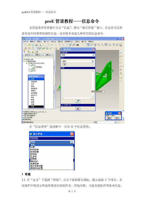
从管道菜单管理器中点击“信息”,弹出“报告管线”窗口,在这里可以查看管道不同类型的属性信息,这里简单讲述几种常用的信息命令。
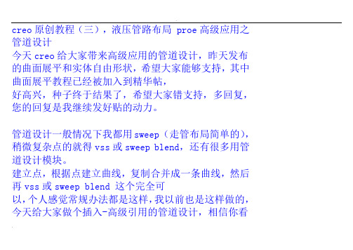
在“信息类型”选项框中一共有11中信息类型:
1 常规
1.1 在“定义”下选择“管线”
,点击下面的箭头图标,提示选取1个项目,在结果栏中将显示所选管线项目的组件名、管线名称、当前直线轧件等基本信息。
直径、长度、壁厚等信息。
点击图标,“结果”栏中的信息以独立窗口的形式显示。
1.3 如果管道设计有保温材料,在“保温材料”定义项的结果中显示保温材料的相关信息:
2 长度
显示所选管线或管段的长度信息
材料清单:显示所有已定义的管道导管材料清单信息。
3 材料清单
4 折弯位置
在“信息类型”中选取“折弯位置”,用鼠标依次点击管道的中心线、参照坐标系(一般选笛卡尔坐标系)完成选取后,在被选取的管道上出现该管道的流
体流向,也是管道的折弯顺序方向,点击“反向”折弯方向改变,同时折弯位置信息表中的信息顺序也随之改变:
折弯机:给出使用数控弯管设备进行加工时的参数文件。
5 折弯机
欢迎大家登录“中国机械资讯网”我的个人空间进行交流和获取更多的proE4.0学习资料。
网址:/?188912/。
creo原创教程(三),液压管路布局proe高级应用之管道设计
creo原创教程(三),液压管路布局 proe高级应用之管道设计今天creo给大家带来高级应用的管道设计,昨天发布的曲面展平和实体自由形状,希望大家能够支持,其中曲面展平教程已经被加入到精华帖,好高兴,种子终于结果了,希望大家错支持,多回复,您的回复是我继续发好贴的动力。
管道设计一般情况下我都用sweep (走管布局简单的),稍微复杂点的就得vss或sweep blend,还有很多用管道设计模块。
建立点,根据点建立曲线,复制合并成一条曲线,然后再vss或sweep blend 这个完全可以,个人感觉常规办法都是这样,我以前也是这样做的,今天给大家做个插入-高级引用的管道设计,相信你看后一定会会经常用到这个的。
管道设计模块我没有用过,如果大家有异议,可以发帖共同交流1.我先建立几个障碍,走管绕过这些障碍.2.建立几个基准面,再建立点,这些点要穿过障碍,不能在每个障碍上,基准面要建立点适当看图,这些基准面和点的建立有一定的经验成分在里面,不过不用担心,即使你现在的面和电建立的不好,到时候可以调整3.点击插入--高级--管道,弹出菜单管理器,这里用默认的就可以,几何就是点线面,空心,你的管道不可能是实心对吧,常数半径,这个可以随意一些,到时候和障碍有冲突,可以设置多重半径,一般情况下我都设置为常数,点完成,输入外部直径我输入10,管道壁厚为1.5,添加点,根据你的管道的走向顺次选取点,别忘了按住ctrl键,到拐弯的时候让你输入折弯半径,这个也有一定的经验在里面,一次不行可多次,一步一步来,点选每个点后,出现个箭头,箭头的方向代表该点所在曲线曲率的方向,也就是切线的方向,选择完最后一个点,点击鼠标中间,可以看到管路建立好了。
如果觉得不满意,可以再调整一下点,教程管道的设计比较简单,实际情况比这个复杂的也有很多,这里只提供思路,做管道设计,尤其是液压系统的设计,建议用这个种方法,比较好控制,如果vss或者sweep blend,单单是合并曲线就够你忙活一会了,有人会问,为什么sweep不行么,我可以告诉你,合并的复杂曲线sweep是扫描不到的,这里就不能用sweep,简单的在一个平面内的简单的曲线可以用sweep。
ProE管道建模的三种方法:扫描、高级管道、管道模块

Pro/E 管道建模的三种方法:扫描、高级管道、管道模块没有接触管道时,感觉管道建模很复杂,其实真正去应用的时候,并没有想象得那么难。
这里我们一起来探讨管道建模,相信你也一定能行。
通常创建管道有三种方法:曲线扫描:这其实是用普通特征来创建管道,建管道比较麻烦;插入→高级→管道:有一定的局限性,比如只能在零件模式下使用,装配模式是出不来管道实体的;应用程序→管道:这是管道模块,功能强大优势明显:如工艺上,多数管道都是在各零件安装定位后安装,与实际设计理念相同。
下面就针对这三种管道建模方法进行探讨,重点放在第三种Pro/E 管道模块上。
所用版本为Pro/E4.0 m050。
本教材地址:Pro/E 管道建模的三种方法:扫描、高级管道、管道模块目录第一种方法:扫描特征.......................................................................................................2 第二种方法:高级管道.......................................................................................................7 第三种方法:管道模块.....................................................................................................12 规范驱动............................................................................................................................22 保温材料............................................................................................................................36 实例....................................................................................................................................40 Pro/E 技术资料、光盘、书籍汇总.. (48)三维网 XinYaZhu2009-5-4winxos 11-01-28winxos 11-01-28第一种方法:扫描特征使用传统的零件创建曲线,扫描成实体的方法。
ProENGINEER Pipe管道教程
第十一章管道的绘制使用PROE创建三维管道一般有三种方法:第一种方法、3维曲线扫描:先绘制一条曲线,然后再以这条曲线为中心线进行扫描成管道状的实体,这个零件的轨迹是空间的,所以不推荐使用扫描来实现。
第二种方法、“插入”高级特征:仅仅是个特征有一定的局限性,比如只能在零件模式下使用,装配模块是出不来管道实体的。
第三种方法、使用管道模块:功能强大优势明显,工艺上,多数管道都是在各零件安装定位后安装,我们设计也是如此,因此管道(piping)只能在装配模式下才可以调用是明智的。
优点如下:(1)方便定义管理多种管线。
(2)布线方法多样、灵活、方便。
(3)方便提取管道信息。
(4)适合于管路复杂的装配设计。
下面以几个实例来讲述管道的建模过程。
实例一:使用“插入”高级特征绘制管道。
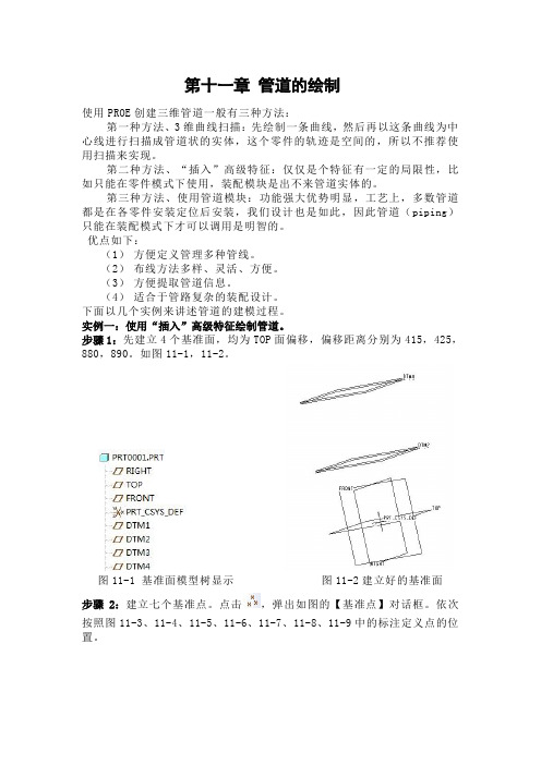
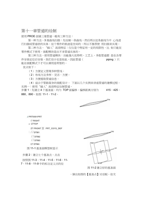
步骤1:先建立4个基准面,均为TOP面偏移,偏移距离分别为415,425,880,890。
如图11-1,11-2。
图11-1 基准面模型树显示图11-2建立好的基准面步骤2:建立七个基准点。
点击,弹出如图的【基准点】对话框。
依次按照图11-3、11-4、11-5、11-6、11-7、11-8、11-9中的标注定义点的位置。
图11-3 PNT0的定位图11-4 PNT1的定位图11-5 PNT2的定位图11-6 PNT3的定位图11-7 PNT4的定位图11-8 PNT5的定位图11-9 PNT6的定位七个基准点建立完毕。
步骤3:选择【插入】→【高级】→【管道】命令。
如图11-10。
图11-10 【管道】命令的选取弹出如图11-11菜单管理器图11-11选取管道命令后弹出的【菜单管理器】点击【完成】,在消息框里输入管道的外部直径25,如图11-12。
图11-12 输入外部直径接着输入侧壁厚度2,如图11-13。
图11-13 输入侧壁厚度在随后弹出的菜单管理器选择依次【单一半径】【整个阵列】【添加点】,如图11-14。
图11-14【连接类型】设置然后再依次选择基准点,顺序为PNT0→PNT1→PNT2→PNT3→PNT4→PNT5→PNT6。
用PROE对工程机械产品的液压系统进行三维布管详细步骤
PROE三维布管操作步骤
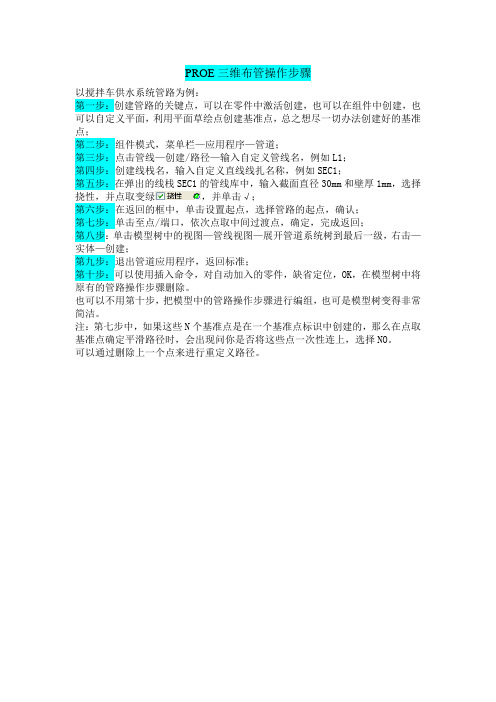
以搅拌车供水系统管路为例:
第一步:创建管路的关键点,可以在零件中激活创建,也可以在组件中创建,也可以自定义平面,利用平面草绘点创建基准点,总之想尽一切办法创建好的基准点;
第二步:组件模式,菜单栏—应用程序—管道;
第三步:点击管线—创建/路径—输入自定义管线名,例如L1;
第四步:创建线栈名,输入自定义直线线扎名称,例如SEC1;
第五步:在弹出的线栈SEC1的管线库中,输入截面直径30mm和壁厚1mm,选择挠性,并点取变绿,并单击√;
第六步:在返回的框中,单击设置起点,选择管路的起点,确认;
第七步:单击至点/端口,依次点取中间过渡点,确定,完成返回;
第八步:单击模型树中的视图—管线视图—展开管道系统树到最后一级,右击—实体—创建;
第九步:退出管道应用程序,返回标准;
第十步:可以使用插入命令,对自动加入的零件,缺省定位,OK,在模型树中将原有的管路操作步骤删除。
也可以不用第十步,把模型中的管路操作步骤进行编组,也可是模型树变得非常简洁。
注:第七步中,如果这些N个基准点是在一个基准点标识中创建的,那么在点取基准点确定平滑路径时,会出现问你是否将这些点一次性连上,选择NO。
可以通过删除上一个点来进行重定义路径。
(注:素材和资料部分来自网络,供参考。
请预览后才下载,期待你的好评与关注!)。
ProE管道建模的三种方法:扫描、高级管道、管道模块
Pro/E管道建模的三种方法:扫描、高级管道、管道模块没有接触管道时,感觉管道建模很复杂,其实真正去应用的时候,并没有想象得那么难。
这里我们一起来探讨管道建模,相信你也一定能行。
通常创建管道有三种方法:曲线扫描:这其实是用普通特征来创建管道,建管道比较麻烦;插入→高级→管道:有一定的局限性,比如只能在零件模式下使用,装配模式是出不来管道实体的;应用程序→管道:这是管道模块,功能强大优势明显:如工艺上,多数管道都是在各零件安装定位后安装,与实际设计理念相同。
下面就针对这三种管道建模方法进行探讨,重点放在第三种Pro/E管道模块上。
所用版本为Pro/E4.0 m050。
本教材地址:Pro/E管道建模的三种方法:扫描、高级管道、管道模块目录第一种方法:扫描特征 (2)第二种方法:高级管道 (7)第三种方法:管道模块 (12)规范驱动 (22)保温材料 (36)实例 (40)Pro/E技术资料、光盘、书籍汇总 (48)三维网 XinYaZhu2009-5-4第一种方法:扫描特征使用传统的零件创建曲线,扫描成实体的方法。
先绘制一条曲线,然后再以这条曲线为中心线进行扫描成管道状的实体,如果管道中心线是空间的,那么轨迹曲线的创建就比较复杂了。
这种方式可以在零件模式和组件模式两种模式下创建。
这里举一空间管道为例进行说明。
1、在一基准面中草绘曲线12、在与上一基面垂直的基准面中草绘曲线2这是两条曲线的空间位置3、我们要利用这两个平面曲线生成空间曲线。
按住CTRL选中这两条曲线;编辑→相交生成所需要的管道空间曲线4、插入→扫描→伸出项选择相交曲线作为轨迹曲线进入管道截面界面,绘制两个圆形,代表管道的外径和内径退出截面,确定,得到如图所示的管道。
实例part:pipe.rar (214.83 KB)第二种方法:高级管道使用零件中的管道特征创建。
这种方式可以在零件模式和组件模式两种模式下创建。
下面以一个变形的晾衣架为例说明高级管道的创建。
proe管道设计教程
第十一章管道的绘制使用PROE创建三维管道一般有三种方法:第一种方法、3维曲线扫描:先绘制一条曲线,然后再以这条曲线为中心线进行扫描成管道状的实体,这个零件的轨迹是空间的,所以不推荐使用扫描来实现。
第二种方法、“插入”高级特征:仅仅是个特征有一定的局限性,比如只能在零件模式下使用,装配模块是出不来管道实体的。
第三种方法、使用管道模块:功能强大优势明,工艺上,多数管道都是在各零件安装定位后安装,我们设计也是如此,因此管道(piping )只能在装配模式下才可以调用是明智的。
优点如下:(1)方便定义管理多种管线。
(2)布线方法多样、灵活、方便。
(3)方便提取管道信息。
(4)适合于管路复杂的装配设计。
下面以几个实例来讲述管道的建模过程。
实例一:使用“插入”高级特征绘制管道。
步骤1:先建立4个基准面,均为TOP面偏移,偏移距离分别为415,425,880, 890。
如图11-1,11-2。
J PRT0001PRTO RIGHT■- Z7TOPZ7 FRONT 簣PRT_CSYS_DEF\ 口 DTM1口 DTM2口 DTM3£7 DTM4图11-1基准面模型树显示步骤2:建立七个基准点。
点击按照图11-3、11-4、11-5、11-6、11-7、11-8、11-9中的标注定义点的位图11-2建立好的基准面,弹出如图的【基准点】对话框。
依次□基薩点乏敕置属性m_C^^_DEF F4 •坐标系}在…上偏移<! 00「礙_ I取消I图11-3 PNT0 的定位图11-4 PNT1 的定位图11-5 PNT2 的定位图11-6 PNT3 的定位图11-7 PNT4 的定位图11-8 PNT5 的定位□華准申图11-9 PNT6 的定位七个基准点建立完毕。
步骤3:选择【插入】-【高级】-【管道】命令。
如图11-10图11-10【管道】命令的选取弹出如图11-11菜单管理器图11-11选取管道命令后弹出的【菜单管理器】点击【完成】,在消息框里输入管道的外部直径25,如图11-12❖输入外部直径飼图11-12输入外部直径接着输入侧壁厚度2,如图11-13❖输入侧壁厚度耳图11-13输入侧壁厚度在随后弹出的菜单管理器选择依次【单一半径】【整个阵列】【添加点】,如图11-14。
使用PROE5.0创建管道教程原创
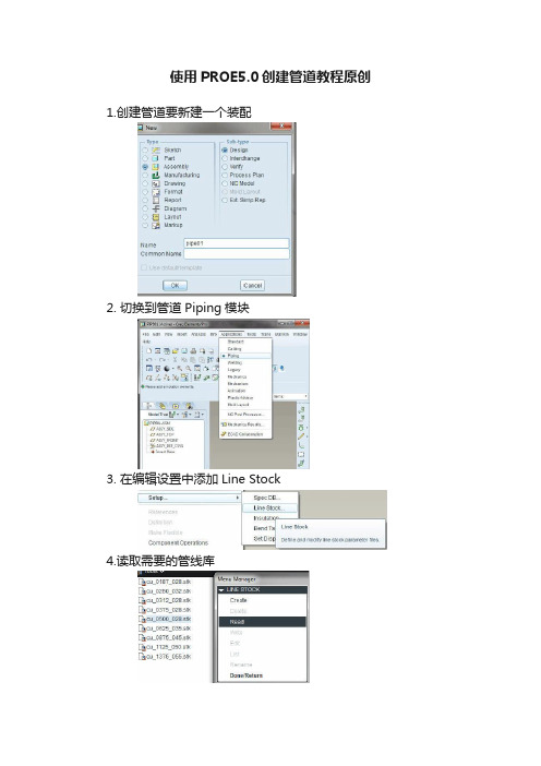
使用PROE5.0创建管道教程原创1.创建管道要新建一个装配
2. 切换到管道Piping模块
3. 在编辑设置中添加Line Stock
4.读取需要的管线库
5. 新建Pipeline
6.可以创建或选择刚刚读取的管线库
7.选择或创建管线库后,会自动切入创建Pipe route
8.选择起始点并延伸
9.这里可以选择圆柱坐标系或球坐标系来做非90度折弯的管子
10.可以创建任意一点,将管子连接到此点
11.选择如图所示将管道实体化
12.选择这支笔可以修改参数,重新选择管线库或编辑管线库参数值注意更新管线库是,管子折弯半径不会变化,需要手动修改!。
- 1、下载文档前请自行甄别文档内容的完整性,平台不提供额外的编辑、内容补充、找答案等附加服务。
- 2、"仅部分预览"的文档,不可在线预览部分如存在完整性等问题,可反馈申请退款(可完整预览的文档不适用该条件!)。
- 3、如文档侵犯您的权益,请联系客服反馈,我们会尽快为您处理(人工客服工作时间:9:00-18:30)。
一、创建线栈一、 Routing Pipelines a) First pipeline 1. Open the BASIC_ROUTING.ASM 2. Enter the Piping module. Click Applications > Piping 3. Read in the 1_Hose line stock file. 4. Create a pipeline feature. Click Pipe Line > Create/Route, enter[Line_1], and select [1_HOSE] as the active line stock 5. Route pipeline from Port3_V on the vessel to Port2_MT 。
b) Second pipeline 1. Create pipeline line_2 2. Set start point , ToPnt/Port > Point/s 3. Follow > Axis > Done, and pick the firstaxis shown Figure 12, and click Done Follow. 4. Again, click Follow > Axis > Done, and pick the second axis inFigure 12. Click Change > Ends > Done > Accept, Drag, andDone, to accept the right side of the axis. Using the cursor, drag the endpoint of the axis to the right andclick. Click Ext Length, and enter [2.5], then click Done andDone Follow. 5. Connect some of the pipe segments. Click Connect > Pipe End,and pick the first pipe end shown below. Click Pipe End again,pick the second pipe end, and click Done and Done Connect. 6. Next, view alternatives to connect the two axes segments. Click Connect > Pipe End, and pick the first pipe end, then click Pipe End again Pick the second pipe end shown below and click Done,and Done Connect. 7. Now try the same routing with a different option. Click DeleteLast, then Set Start, Pipe End, and pick the first pipe end shownabove. Click To Pnt/Port, Pipe End, and pick the second pipe end.Notice the difference in the pipeline. 8. Complete the routing of LINE_2 ,CREAT SOLIDc)Create LINE_3 and LINE_4 using different Point options.1. Create a new pipeline. Click Pipe Line > Create/Route, enter[LINE_3], and select [1_HOSE]as the active line stock.2. Set Start ToPnt/Port ToPnt/Port3.DOWN4.To assist in Routing, it is possible to use an array of datum points.Route LINE_4 using thistechnique. Create a new pipeline. ClickPipe Line > Create/Route, enter [Line_4], and select [1_HOSE]as the active line stock.5.Click Set Start > Entry Port, and pick Port2_MT on the multitank.Click ToPnt/Port > Point/s,and pick the point just beyondPort2_MT.6.Set Start ToPnt/Port ToPnt/Portd)Route LINE_5 using flexible shape pipeline.1.Create a new pipeline. Named line_52.Create some disjointed pipeline segments following the axesshown below. Click Follow >Axis > Done, and the first axisshown below, and Done Follow. Repeat for the second axis.3.Change the current piping environment. Click Pipe Environment> Line Shape > Flexible >Done > Done Return. To route the flexible line, click Set Start, and pick one of the pipeends,followed by ToPnt/Port, and the other pipe end.4.Make solide)The final pipeline will use sketches for routing.1.Create a new pipeline. Named [line_6]2.Before routing the next pipeline, change the Pipe Environmentdefaults. Click PipeEnvironment > Line Shape > Straight >Done > Corner Values > [3.00] > Done Return.3.Create some disjointed pipeline segments following the axesshown. Click Follow > Axis >Done, and pick the first axis shownbelow. Click Change > Ends > Done > and accept theouter pointof the axis, then click Drag, and ing the cursor, drag the endpoint of the axis outward and click.Click Ext Length, and enter [3.0], then click Done and DoneFollow.Repeat for the second axis, using [2.0] as the extensionvalue.4.Next, the first portion of the pipeline will follow a sketch. ClickFollow > Sketch > Done.For the sketching plane, click MakeDatum > Through, and pick the first axis in Figure 26.ClickParallel, and pick the top surface of the Base.5.Down the sketch as follow6.After completing the sketch, click Done > Done Follow, and theCONNECT menu shouldappear. Notice how the new defaultradius from the line stock set in the Pipe Environment is applied to the corners of the sketch. Click Pipe End, and pick the end of the follow axis segment, then click Done, and Done Connect. When the free end of the pipeline highlights, click Quit Connect and return to the ROUTE PIPE menu.7.Before sketching the next segment,change the PipeEnvironment defaultsagain. Click Pipe Environment >CornerType > Miter Cut > Done >Square > Done, and Done Return.8.Sketch the second portion ofthe pipeline. Click Follow >Sketch >Done. For the sketching plane,click Make Datum > Through, andpickthe axis as shown in Figure 29. ClickNormal, and When the sketch is completed, click Done > Done Follow, and the9.CONNECT menu should appear. Click Pipe End and pick the end of the follow axis segment,thenclick Done, and Done Connect. When the free end of the pipelinehighlights, click Quit Connect.Sel ByMenu > Sel By Menu > Basic_Routing.asm > Datum > Name >A‐Right_1, and Done.10.The final segment will be completed using flexible line. Changethe current pipingenvironment. Click Pipe Environment > LineShape > Flexible > Set Length > Done > Done Return.11.To route the flexible line, click Set Start, and pick one of the pipeends, followed byToPnt/Port, and the other pipe end. Enter [5.5]as the fixed length of pipeline, and click Done Return.12.Make solid.第三章 进阶布线技术一、Using Additional Routing Techniquesa)Route the first pipeline1.Open the ADDL_ROUTING.ASM2.Read in the 1_Hose line stock file.3.Create a pipeline feature nemed [line_1]4.Click Set Start,and select PORT1_V,and Extend [3.0]5.Click Extend > Direction, and select the upper horizontal edge ofthe Base. Click EnterLength, note the direction of the arrow, andenter [‐4.0].e Extend Direction a little differently, the same direction ,extend [5]7.Route the pipeline towards the Base. Click Extend > UpTo, andpick the Base surface asshown in Figure 12. Click Enter Length,and enter [7.0]8.Begin routing from the end of the pipeline. Click Set Start, andselect the PORT1_P on thePump as shown in Figure 12. Extendthe pipeline in the Z‐axis direction of the port. ClickExtend, enterthe length, and enter[3.0]9.Click Extend > UpTo, pick the surface on the pump in Figure 12,click Enter Offset, andenter [-2.0]. Complete the routing byclicking Connect, and pick each free pipe end, thenclick Done >Done Connect. Refer to Figure 13. DO NOT make a solid pipe atthis timeb)Route the second pipeline1.Create a pipeline feature and nemed [line_2]2.Click Set Start, and select PORT2_V, Extend and Enter Length, and enter [3.0].3.UpTo, pick the first surface of the bracket, than up and Offset [3.0] of the other surface,change the corner value to [0.75]4.Extend > UpTo base surface and offset [2.0]5.Begin routing fromthe end of thepipeline.6.Extend [3]7.Y‐Axis [6]8.x‐Axis [6]9.Changing LineShape to Flexible10.To Pnt/Port,finishc)Begin the third Pipeline. Use a combination of Follow Curve and Extend1.Create a pipeline feature nemed [line_3]2.Set stard point,Extend andEnter Length, and enter [5.0].3.Click Follow > Axis > Done,and select A_1 on the Block,and click Done Follow.4.Click Follow > Curve, Done,pick the first curve shown inFigure 19, then click SelectAll > Done, Done Follow.Repeate Connect to create FOURconnections between the pipesegments6.Click Extend > Direction,pickthe underlying datum curve inFigure 20 and extend to theleft[4.0]. Click Done andDone-Return.d)Begin Routing LINE_4. Use Follow Pipeline for the major routing.1.Create a pipeline feature nemed [line_4]2.Begin routing LINE_4 from the unused port on the first Pump.Click Set Start, and pickPORT2_P on the pump as shown inFigure 21. Route the pipeline using various extendcommands, andclick ToPnt/Port to arrive at APNT0. (此处是随意布线)3.Route the next segment using a follow pipeline. Click Follow >Pipeline > Done, pick Line_3,click Specify, and Done to specify the start and end segments as shown in Figure 22.4. Start Point, Done, pick APNT0, and click Done Follow.5.connect the segmenting Routing commands of your choice , complete the routing for the two lines asfollow.e)Lines 5 and 6 will require some branching. Create the Pipelinesand Branch into Line 2, createdearlier.1.Create a pipeline feature nemed [line_5]2.Begin routing LINE_5 from the Multi Tank as shown. Click Follow > Axis > Done, pick axisA_4, and then click ChangeEnds > Done. Accept the outer end. Use Drag and Ext Length to extend past the axis [6.0]. Click Done > Done Follow. Click Set Start > Pipe End, and pickthe end of the pipeline.3.Click Branch > Perpendicular(垂直,正交), and pickLINE_2. Click Done-Return whenfinished. Refer to Figure 24.4.Create another pipeline featurenamed [line_6]5.Begin routing LINE_6 fromA_8 on the same Multi Tank,and use the same Follow andChange End procedure as withA_4.6. In order to create this branch,you will create a datum pointon LINE_2. Click Branch > ToPoint > Create Pnt, pick alocation as shown on LINE_2,click Length Ratio, and enter[0.75]. Referto Figure 25.二、Using the EZRouter and Square1.Change the working directory to EZ_Route_Rect and open theEZ_ROUTE_RECT.ASM file.2.Read in the [Circ_050] and [Rect_1_2] line stock fileb)Route a pipeline that will represent a duct(电缆槽) using square pipe.1.Click PipeLine > Create> ’pl2’ >Rect_1_2.2.Click Set Start. Pick the Port2_V Csys.3. Click EZRouter and use withthe saved views. Route thepipe similar to Figure 42.4.Make the pipeline solid andtype [DUCT_1].5.6.7.第四章 Modifying Pipelinesa)Some new routing point locations are needed in LINE_2. Useinsert point to accomplish this.1.Open the Modify_Basic_Routing.asm2.Before modifying the pipeline, change the display of LINE_2 to centerline.3.Insert a point for a routing location. Click Route, pick LINE_2,and click Insert Point. Pickthe pipe segment shown to insert the point on. Click Create > Static > Done,4. Use [3.5] [3.5] [0.75] to creat the point.5.Insert another point into the pipeline , Create > Dynamic > Done.b)Use the SEL BY Menu technique to select an empty pipeline.1.Create a temporary pipeline. Click Pipe Line > Create, enter [temp], 1_HOSEc)Make several modifications to LINE_61.Click Route, pick the pipeline shown in Figure 12, click Mod Dim,and pick the sketchedsegments. Modify the [0.75] dimension to[-6.0] and click Done Sel. Pro/E automaticallyattempts toregenerate the Pipeline, and it fails because this flexible line wasconstructedwith the Set Length option, and this modificationexceeds the set length.(修改草绘中0.75到-6)2.Make solid and regenerate3.From the PIPE MODIFY dialog box, select CORNER, pick theupper left mitered corner asshown in Figure 14, and change theType to Bend with a radius of [3.0]. Use Select Cornerto pickthe upper right corner, and change its type to Fitting. Click Apply> Close, andRegenerate Automatic.(用“管道修改”修改两个拐角,左边修改为半径为3的折弯,右边修改为管接头拐角,自动再生)4.The solid pipe fails because it has split into two pieces. Delete the solid and recreate. ClickQuick Fix > Delete > Confirm, and Yes to exit Resolve mode. Click Make Solid and edit the new pipeline names to be [MOD_1] and [MOD_2]. Notice the opening between the twosolid pipe segments allows for a fitting to be placed. Referto Figure 15.(再生失败后删除实体,重新命名为两段)d)The section of pipe between the arches requires a diagonalmiter.1.Click Mod Pipe, pick thepipeline, clickDone Sel, change Bend to Diag Miter Cut,and entera value of [5.0] [2] . Click Apply,note the changes and close.2.Click Regenerate > Automatic toupdate the solid pipe.e)Modify the line stock on some pipelines.1. Click set >Line Stock > Read,and select 050_PIPE2. Mod Pipe > Line Stock, pickLINE_3, and click DoneSelect.Select 250_LINE and clickApply. Click SelectSegment again, selectLINE_FLEX, click Done Select,change to 050_PIPE,click Apply, Close, and Regenerate Automaticf)Modify some built-in angular dimensions in the multi-tank tochange the pipelines1.Click Mod Dim and pick the four nozzles on the multi‐tanks as shown in Figure 19.Modify the four 60 degrees dimensions to[90].2.Regenerate Automaticg)After modifying nozzle angles, one flexible line is stretched too tight, and the other is toocramped. Make necessary modifications to the flexible pipelines.1.Click Mod Pipe, and Flex Shape, select the LINE_FLEX, and click Fixed Length. NoticePro/E provides the current value of theflexible line. Enter [20.0], click Apply, and notehow the linebows out. Click Select Segment, pick the “S” shape in LINE_6,and change thelength to [10.0]. Click Apply, Close, and Regenerate.(前一步骤修改成了12,此处改到10)二、Using Replace Modea)The pipeline goes straight through the tank. Correct thisproblem by sketching the pipeline inthis area.1.Open REPLACE_MODE_ROUTING_E2.Click Route,Replace > Enter Replace第五章 Fittings一、Inserting fittings in a Piping Systema)Prepare some corners for fittings1.Open the FITTINGS_MOD_ROUTING.ASM2.Fittings should always be placed before solid pipes are made. Pick each pipe above inFigure 26, and use the right mouse button to delete them.(接头一般在管道实体创建之前放置,删除图示管道实体)3.Click Route, pick the pipeline as shown above in Figure 27. Click Redefine, pick thesegment again, and click Change > Sketch >Done > Sketch. Modify the sketch as in Figure28. Click Doneand Done Follow when finished.(修改草绘为接头准备)4.Modify the corners as shown in Figure 29 to fitting corners. Click Mod Pipe > Corner, pickthe three corners, and click Done Sel.Change the type to Fitting > Apply. Click Close.5.Insert three corner fittings. Click Fitting > Insert > Corner >1EL90THRD, pick the corner asshown in Figure 30, and click Done. Repeat for the other corners shown.6.Insert another corner fitting. Click Fitting > Insert > Corner >1EL45 and pick the cornershown below. Click Done, and DoneReturn.7.One of the fittings should be a corner elbow. Click Fitting >Replace, pick the fitting asshown in Figure 32, and click Manual> Done > 1EL90 > Open, then pick the pipeline corner.Click Done, and Done- Returnb)Place some additional fittings from the Multi_Fitting familycreated in the last exercise1.Click Fitting > Insert > Straight Break > Multi_Fitting > Open >The Generic > Open. ClickCreate Point. Pick the location as shown in Figure 33. Pick Length Ratio and enter [0.5].Pick the datum point on the fittingin the subwindow and click Done2.Click Fitting > Insert > Straight Continuous > Multi_Fitting >Open > Multi_BR1 > Open.Create a point ½ way along thepipeline as shown in Figure 34. Click Create Point. Pick the location shown in Figure 34. Pick Length Ratio and enter [0.5].Pick the datum point on the fitting in the subwindow, and click Done.3.The orientation of the fitting above needs to be changed. Click Redefine, select the fitting,and click Orientation. Click Flip, and Done.4.Click Redefine, select the fitting, and click Orientation a second time. Click Twist > EnterValue, enter [45] > Done > Done >Done, and Done-Return. Your assembly should resembleFigure38.c)Next, create some extract models for documentation purposes.1.Click Extract Model > Extract. Enter [EXT_LINE_1], and pick allcomponents in LINE_1. Click Done Sel,Done. Repeat theprocess, creating two more extract models for LINE_2 andLINE_6 as shown in Figure 39.Notice these models ARE addedto the MODEL TREE for this assembly as components, however,they maybe deleted from the assembly so as to not interfere with aBOM, and can still be opened independently.2.Repeat ,repeat ……第六章 Piping Information and Drawings一、Extracting Bend Information1.Open the INFO_DRW_ROUTING assembly.2.Select ANALYSIS > MODEL ANALYSIS, and GLOBAL INTERFERENCE from the TYPEdrop down list. Notice there are at least five pairs of interfering components. Use theup/down arrows to investigate each pair(查看全局干涉)3.Investigate the information options in the PIPING INFO dialog box. Select INFO from thePIPING menu (or INFO, PIPING from the pull-down menu). The PIPING INFO dialog boxappears, with the default Info Type as General, and the drop down option set to Pipe Line(查看管道信息对话框,使用“常规”和“管线”“管段”)4.Pick the pipeline shown in Figure 6 and read the information provided. Change the dropdown option to Segment, and then pick the segment shown in Figure 6. Notice theincreased information.5.Generate a BOM. Select BOM from the drop down list. Scroll down the window to viewthe BOM. For easier viewing, click Info. Close the large info window when finished.6.Select Length from the INFO TYPE drop down list. Notice there are several options: PipeLine, Segment, Stock, as well as Pre/Cut or Centerline. Select PIPE LINE > CENTERLINE,and pick the pipeline shown (LINE_6). (查看管段的长度,查看管线6的长度)7.Change the Length Type to Pre/Cut and observe that the length is identical in this case(58.32).(使用预切割模式和中心线模式查看管线6长度)8.Mod these corners as follow9.Repeat the 7th ,(注意到两种模式下的管线长度不一样)10.Change the definition drop down from Pipe Line to Line Stock. Notice the system lists allline stocks used in this assembly. Select 1_HOSE, and Pro/E calculates the total length ofraw 1_HOSE linestock required for this assembly.(查看线栈1_HOSE的管段长度)b)Take advantage of parameters in the Line Stock, andperform a pipe check operation.1.Change the Info Type to Check Pipe, and pick the same pipeline segment as in Figure 15.Notice the various violations. Use the up/down arrows to highlight the geometry.2.click Linestock > Edit >1_HOSE > Check Pipe, and change the MIN_BEND_SEPARATIONto [2.00], the MIN_STRAIGHT_LENGTH_END to [1.00]. Click OK > Done-Return,and Regenerate > Automatic.(将最小折弯间隙改为2,最小直段长度为1)3.Repeat the 1sd (重复第一步,发现违规减少)c)Generate Bend Machine and Bend Location Data for a pipeline.1.Set the Display of the pipeline as shown to centerline2.Click Info > Piping > Bend Location, and pick the segment and coordinate system, clickDesignate for Report Setup, and Info. Save the analysis. Click Saved Analyses, enter[BEND_LOC], and [Save]. (注意,此处需要保存报告)3.Change the Info Type to Bend Machine and pick the segment as in Figure 19. (Be sure toflip the direction of the arrow, if necessary), click Designate for Report Setup and Info.Save the analysis.Click Saved Analyses, enter [BEND_MACH], and [Save]. Close the dialog box when finished. (保存折弯机信息)4.Set the Display of the pipeline back to Solid. (不要关闭窗口)d)Create a drawing which extracts bend machine and location data from LINE_6, and also usesa custom BOM with repeat regionparameters.1.Click File > New > Drawing, and enter [Pipe_Info], OK,INFO_DRW_ROUTING.ASM asthe default model, no template, size C and click OK.2.Create a view of the entire assembly. Click Views > Add View >General > Full View > NoXsec > Unexploded > Scale > Done,pick a point in the upper left corner of the screen, andenter [0.20].Turn off the display of all datum features, and change the displayto No Hidden.3.Two tables have been saved in your directory that contain onlysome plain text. Place themon the drawing. Click Table >Save/Retrieve > Retrieve > Bend_Loc._Table.tbl > OK, andplace the table on the drawing. Repeat for the Bend_Machine_Table.tbl. Position the tablesas shown in Figure 20.(从文件插入两个表格)4.Create a repeat region in the first table. Click Table > Repeat Region > Add > Simple5.Enter the following parameters in the first table6.Enter the following parameters in the second table7.For each table, click Repeat Region > Attributes, select the region, and click No Duplicatesand Recursive > Done, then Update Tables.(设置无多重记录,递归的)e)Create the Bill Of Materials.1.Click Table > Save/Retrieve> Retrieve > PIPING_BOM_TABLE.tbl > Open,(插入BOM)2.For each region, click Repeat Region > Attributes, select the region, and click No Duplicatesand Recursive > Done and Update Tables. Click Filters > By Item, select the three extract models and the assembly, and click Done Sel > Done.(定义无重复,递归,过滤)3.Click Attributes > Start Index, select the lower region, and then the upper region. Click SortRegions, select the upper region,click Add > Forward, select the name column, then click Done Sel> Done. Refer to Figure 25.(定义起始编号)4.Show the BOM balloons. Click BOM Balloon > Set Region,select the upper region, andclick Show > All. Use Detail Create Balloon for the lower region. Adjust the balloons using Detail Move or Mod Attach.(定义球标)。