ECOTTER GK-120框型光电说明书
Exideal LED EX120小排灯中文说明书
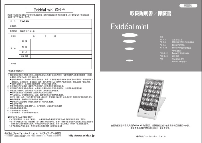
由衷的感谢您对我司产品[Exideal mini]的购买。
请仔细阅读操作使用说明书后再使用本产品。
本操作使用说明书底面含保修卡,请妥善保管。
1
2
LED照射
面板背面
一个LED圆周内置
5个超高辉度LED
最大LED输入功率5.7瓦
做为家用型美容仪已经达到高标准LED瓦数。
边按摩边美容护理边打电话边美容
护理
Exideal专用护眼镜
27500日元(不含税价格)
Exideal专用化妆水Exideal及Exideal mini通用商品
胳膊的内侧用香皂清洗后,用毛巾擦干。
1将洗过的地方搽上化妆水后,放置48小时。
化妆水涂10日元硬币大小的范围,自然干燥。
2确认皮肤有无异常。
48小时内皮肤无异常,表示皮肤敏感测试合格,请使用本产品。
3皮肤敏感试验,是为了防止出现因过敏肌肤出现问题而做的简单测试,使用前请务必执行。
Exideal专用化妆水
※进行皮肤测试的那部分不要沾水,搓蹭。
※涂抹部发生疹子、发红、发痒、刺激等异常情况时,马上中止皮肤测试,用水冲洗。
※試験测试的结果,异常时请停止使用,并向专业医师咨询。
注 意
■特长:通过胶原质的配合使肌肤变得光滑细嫩。
■注意事项:产品的内面印有[使用上的注意],请务必仔细阅读。
Exideal保湿化妆水(头皮用精华液)
Exideal专用化妆水的皮肤敏感测试操作说明
95000日元(不含税价格)
3000日元
(不含税价格)1500日元
(不含税价格)
3500日元
(不含税价格)。
UltraPeel自凝胶照片抗剧照片胶片用户指南说明书

• Easy handling — not tackyIKONICS Imaging for additional exposure times.Suggested Light Sources and Exposure TimesLight Source5 KW Metal Halide 40 in/100 cm 10-15 sec26- 1KS (1 KW) 18 in/45 cm 10-20 secLetralite n/aQuickImage n/aIMAGE DEVELOPMENT1. P osition the exposed film in an upright vertical position with the emulsion (dull) side facing outward, clipping the film to support plate in the washout area.2. W ash out film with water up to 120°F (49° C). The warmer the water the faster the washout. UltraPeel can be processed by using the TriggerJet ® Washout Nozzle with the brass flat spray attachment at 50-80 psi (3.5-5.5 bar) or a pressure washer between 400-1200 psi (28-83 bar).3. U sing either method, spray in a slow and even motion until the image area develops clear. When using high pressure, do not concentrate on one spot as delamination of emulsion from the carrier sheet may occur. A gentle, steady sweeping motion from about 8-12 inches (20-30 cm) away eliminates this potential. High pressure water is recommended for very fine detail and halftones.4. T he entire surface area of the film must be washed to ensure adequate adhesion.5. Wash until the blast area is completely clear of emulsion.Suggested Washout Guidelines TriggerJet ® 1–2 minutesPressure WasherA pressure washer will reduce washout time to under 1 minute in most cases.NOTE: Washout times by either method will be influenced by the amount of detail in the artwork (longer), amount of film being developed, water temperature and amount of water pressure used.Do not wash UltraPeel film under running water from a faucet.DRYING OF MASK1. Remove excess water from mask to accelerate drying times.2. Dry the mask for 30-60 minutes at room temperature; film shouldbe uniform in color. High humidity will extend the drying time. At100°F (39°C), drying will take approxi-mately 20-30 minutes. For best results, return to room temperature before applying.When storing processed UltraPeel masks for later use, apply to SiliconRelease Paper. Masks may be stored for up to one month.IMAGE TRANSFER • U ltraPeel are repositionable.Simply apply the mask to the sub-strate by lightly pressing down on the mask. If repositioning is required remove the mask and realign. • O nce the mask is positioned properly, apply firm pressure to the back of the mask using a plastic burnisher to ensure firm contact of the mask to the substrate.• A void wrinkles or large air pockets. Air pockets under the mask may cause lack of adhesion resulting in blow-offs during blasting. • A good transfer may still result in very small bubbles on the mask surface which will not interfere with either the transfer or the blasting. • Remove the carrier sheet from the mask by flicking a corner with your fingernail or an X-ACTO ® knife. Once removed, press down on the image area with your thumb to assure firm contact, paying special attention to fine details and small lettering.BLAST1. Hold the blast gun 6-8 inches (15–20 cm) away from the object and perpendicular to its surface.2. Recommended maximum pressure for a pressure-pot sandblast system is 40 psi (2.75 bar). A siphon (or suction) sandblast system should not exceed 80 psi (5.5 bar).3. Grit size should be 150 or finerdepending on the image detail. Recommended abrasive media is either pure aluminum oxide or silicon carbide. All manufacturer safety precautions should be closely followed.4. Recommended blasting temperature is 68°F (20°C) or higher. Blasting in lower temperatures may result in loss of adhesion or blow-offs.5. S tage carving can be accomplished with UltraPeel byputting separation lines around the area you wish to peel away and reblast.REMOVE MASK• Peel the mask from the substrate. Fine pieces of film can beremoved by rolling them off with your finger tips. Caution: be careful not to scratch the substrate.• Or, soak the object in water for 10-15 minutes.COLOR FILLINGColor filling is a popular way to add a unique touch to sandcarved projects. Once the piece has been sandblasted, use pressurized air to remove any loose abrasive from the etched area. The photo resist will protect the area you do not want to color. A thin paint coating is preferable since excess paint will dry over the top of the photo resist, causing the paint to pull away from the etched surface during resist removal. Please contact your IKONICS Imaging ™ representative for information on the benefit and use of color filling.7FORM PB54 Rev. 200804A dryer, such as the PB 500 (shown) with heated circulating air will significantly reduce drying time.NOTE: Used alone, UltraPeel films are not suitable films for use with acrylic substrates. The peel after sandblasting is difficult, and becomes more difficult if the film and substrate are soaked in water. Please contact your IKONICS Imaging representative for further details.AN IKONICS COMPANY ISO 9001 CERTIFIED NASDAQ LISTED: IKNXIKONICS Imaging, 4832 Grand Ave., Duluth, MN 55807, USAPhone (218) 628-2002 Toll Free (800) 643-1037 Fax (218) 628-2064E-mail ***********************Web 。
格林光学产品说明书:CSM_E3Z-LT_LR_LL_DS_E_6_8 编程手册
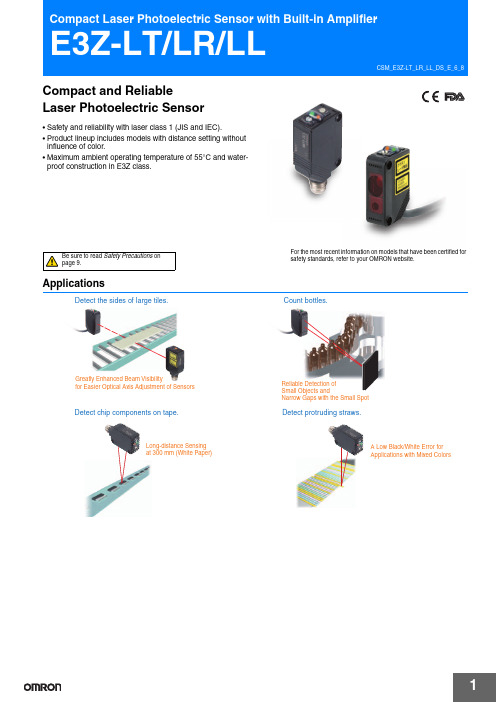
For the most recent information on models that have been certified for safety standards, refer to your OMRON website.ApplicationsGreatly Enhanced Beam Visibilityfor Easier Optical Axis Adjustment of SensorsDetect the sides of large tiles.Detect chip components on tape.Long-distance Sensingat 300 mm (White Paper)Small Objects andNarrow Gaps with the Small SpotCount bottles.Detect protruding straws.A Low Black/White Error for Applications with Mixed ColorsCompact and ReliableLaser Photoelectric Sensor•Safety and reliability with laser class 1 (JIS and IEC).•Product lineup includes models with distance setting without influence of color.•Maximum ambient operating temperature of 55°C and water-proof construction in E3Z class.Be sure to read Safety Precautions on page 9.E3Z-LT/LR/LLOrdering InformationSensors (Refer to Dimensions on page 11.)*2.Values in parentheses indicate the minimum required distance between the Sensor and Reflector.AccessoriesSlits (A Slit is not provided with a Through-beam Sensor. Order a Slit separately if required.) (Refer to Dimensions on page 14.)Reflectors (A Reflector is required for each Retro-reflective Sensor: A Reflector is not provided with the Sensor. Be sure to order a Reflector.)(Refer to Dimensions on page 14.)Note:If you use the Reflector at any distance other than the rated distance, make sure that the stability indicator lights properly when you install the Sensor.Slit width Sensing distanceMinimum detectable object(reference value)Model Contents0.5 mm dia.3 m0.1 mm dia.E39-S65AOne set(contains Slits for both the Emitter and Receiver)NameSensing distanceModelRemarksRated valueReference value Reflector ---15 m (300 mm)E39-R1•Retro-reflective models are not provided with Reflectors.•Separate the Sensor and the Reflector by at least the distance given in parentheses. •The MSR function is enabled.7 m (200 mm)---E39-R12---7 m (200 mm)E39-R6Red lightE3Z-LT/LR/LLMounting Brackets A Mounting Bracket is not provided with the Sensor. Order a Mounting Bracket separately if required.(Refer to Dimensions on E39-L/E39-S/E39-R.)Note:When using a Through-beam Sensor, order one Mounting Bracket for the Receiver and one for the Emitter*1.Cannot be used for Standard Connector models with mounting surface on the bottom. In that case, use Pre-wired Connector models.*2.Cannot be used for Standard Connector models.Sensor I/O Connectors (Sockets on One Cable End)(Models for Connectors and Pre-wired Connectors: A Connector is not provided with the Sensor. Be sure to order a Connector separately.)(Refer to Dimensions on XS3)Note:When using a Through-beam Sensor, order one Mounting Bracket for the Receiver and one for the Emitter *1.The connector will not rotate after connecting.*2.The cable is fixed at an angle of 180° from the sensor emitter/receiver surface.Appear-anceModelQuantityRemarksAppear-anceModelQuantityRemarksE39-L153*11Mounting BracketsE39-L98*21Metal Protective Cover BracketE39-L104*11E39-L150 1 set(Sensor adjuster)Easily mounted to the aluminum frame rails of conveyors and easily adjusted.For left to right adjustmentE39-L43*21Horizontal Mounting BracketE39-L1511 setE39-L142*21Horizontal Protective Cover BracketE39-L441Rear Mounting BracketE39-L144*21Compact Protective Cover Bracket (For E3Z only)SizeCableAppearanceCable type ModelM8Standard2 m 4-wireXS3F-M421-402-A 5 m XS3F-M421-405-A 2 m XS3F-M422-402-A 5 mXS3F-M422-405-AStraight *1L-shaped *1 *2E3Z-LT/LR/LL Ratings and SpecificationsSensing method Through-beamRetro-reflective with MSRfunctionDistance-settable (BGS models)Response Standard response High-speed responseModelNPNoutputE3Z-LT61/-LT66E3Z-LR61/-LR66E3Z-LL61/-LL66E3Z-LL63/-LL68ItemPNPoutputE3Z-LT81/-LT86E3Z-LR81/-LR86E3Z-LL81/-LL86E3Z-LL83/-LL88Sensing distance60 m 0.2 to 7 m(when using E39-R12)White paper (100 × 100 mm):20 to 300 mmBlack paper (100 × 100 mm):20 to 160 mmWhite paper (100 × 100 mm):25 to 300 mmBlack paper (100 × 100 mm):25 to 100 mmSet distance range---White paper (100 × 100 mm):40 to 300 mmBlack paper (100 × 100 mm):40 to 160 mmWhite paper (100 × 100 mm):40 to 300 mmBlack paper (100 × 100 mm):40 to 100 mmSpot diameter(reference value)5-mm dia. at 3 m0.5-mm dia. at 300 mmStandard sensing object Opaque: 12-mm dia. min.Opaque: 75-mm dia. min.---Minimum detectable object(reference value)6-mm-dia. opaque object at 3 m0.2-mm-dia. stainless-steel pin gauge at 300 mm Differential travel---5% max. of set distanceBlack/white error---5% at 160 mm5% at 100 mm Directional angle Receiver: 3 to 15°---Light source (wavelength)Red LD (655 nm), JIS CLass 1, IEC Class 1, FDA Class 2Power supply voltage12 to 24 VDC±10%, ripple (p-p): 10% max.Current consumption35 mA (Emitter 15 mA,Receiver 20 mA)30 mA max.Control output Load power supply voltage: 26.4 VDC max., Load current: 100 mA max., Open collector outputResidual output voltage Load current of less than 10 mA: 1 V max.Load current of 10 to 100 mA: 2 V max.Output mode switching Switch to change between light-ON and dark-ONProtection circuits Reversed power supplypolarity protection, Outputshort-circuit protection, andReversed output polarityprotectionReversed power supply polarity protection, Output short-circuit protection, Mutual interference pre-vention, and Reversed output polarity protectionResponse time Operate or reset: 1 ms max.Operate or reset: 0.5 ms max. Sensitivity adjustment One-turn adjuster Five-turn endless adjusterAmbient illumination (Receiver side)Incandescent lamp: 3,000 lx max. Sunlight: 10,000 lx max.Ambient temperature range Operating: −10 to 55°C, Storage: −25 to 70°C (with no icing or condensation)Ambient humidity range Operating: 35% to 85%, Storage: 35% to 95% (with no icing or condensation)Insulation resistance20 MΩ min. at 500 VDCDielectric strength1,000 VAC, 50/60 Hz for 1 minVibration resistance Destruction: 10 to 55 Hz, 1.5-mm double amplitude for 2 hours each in X, Y, and Z directions Shock resistance Destruction: 500 m/s2 3 times each in X, Y, and Z directionsDegree of protection IP67 (IEC 60529)Connection method Pre-wired cable (standard length: 2 m):E3Z-L@@1/-L@@3 Standard M8 Connector:E3Z-L@@6/-L@@8Indicator Operation indicator (orange)Stability indicator (green)Emitter for Through-bream Models has power indicator (orange) only.Weight (packed state)Pre-wired cable(2 m)Approx. 120 g Approx. 65 gStandardConnectorApprox. 30 g Approx. 20 gMaterial Case PBT (polybutylene terephthalate)Lens Modified polyarylate resin Methacrylic resin Modified polyarylate resinAccessories Instruction manual (Neither Reflectors nor Mounting Brackets are provided with any of the above models.)E3Z-LT/LR/LLEngineering Data (Reference Value)Parallel Operating Range Through-beam Models Through-beam Models Retro-reflective Models E3Z-LT @@E3Z-LT @@ + E39-S65AE3Z-LR @@Operating Range at a Set Distance of 300 mm Operating Range at a Set Distance of 40 mm BGS Models BGS Models E3Z-LL @@E3Z-LL @@Excess Gain vs. Set Distance Through-beam Models Retro-reflective Models E3Z-LT @@E3Z-LR @@Close Range Characteristics BGS ModelsE3Z-LL @1/-LL @6E3Z-LL @3/-LL @8−−−50D i s t a n c e Y (m m )−−−−D i s t a n c e (m m )Distance (m)−60−40−20D i s t a n c e Y(m m )−−−−−Distance X (mm)O p e r a t i ng r a n g e Y (m m )−−−O p e r a t i n g r a n g e Y (m m )Distance (m)Ex c e s s g a i n r a t i o (m u l t i p l e )Distance (m)E x c e s s g ai n r a t i o (m u l t i p l e )White paper Setting:300 mmBlack paper White paper Blackpaper S e n s i n g d i s t a n c e (m m )Setting:40 mmSetting:40 mm Setting:160 mm White paper Black paper White paper Black paper S e n s i n g d i s t a n c e (m m )Setting:300 mmSetting:40 mmSetting:40 mmSetting:100 mmE3Z-LT/LR/LLSensing Distance vs. Sensing Object Material BGS ModelsE3Z-LL @1/-LL @6White Paper with a Set Distance of 40 mmE3Z-LL @3/-LL @8White Paper with a Set Distance of 40 mmE3Z-LL @1/-LL @6White Paper with a Set Distance of 300 mmBGS ModelsE3Z-LL @1 (LL @6)E3Z-LL @3 (LL @8)Inclination Characteristics (Vertical)Inclination Characteristics (Horizontal)BGS Models BGS Models E3Z-LL @@E3Z-LL @@paper board paper rubber surface S e ns i n g d i s t a n c e (m m )paper b oard paper r ubb ers u rface S e n s i n g d i s t a n c e (m m )paper board paper rubber surfaceS e n s i n g d i s t a n c e (m m )Set distance (mm)H y s t e r e s i s (%)Set distance (mm)H y s t e r e s i s (%)−5−10−15−20S e n s i n g d i s t a n c e v a r i a t i o n (%)Inclination angle θ (°)−5−10−15−20S e n s i n g d i s t a n c e v a r i a t i o n (%)Inclination angle θ (°)E3Z-LT/LR/LL I/O Circuit DiagramsNPN OutputThe model number of the Emitter is expressed by adding "-L" to the set model number (example: E3Z-LT61-L 2M), the model number of the Receiver, by adding "-D" (example: E3Z-LT61-D 2M.) Refer to Ordering Information to confirm model numbers for Emitter and Receivers.E3Z-LT/LR/LLPlugs (Sensor I/O Connectors)NomenclatureM8 4-pin ConnectorsXS3F-M421-402-A XS3F-M421-405-AXS3F-M422-402-A XS3F-M422-405-ADistance adjuster (5-turn endless)Stability indicator(green)Operation selectorOperation indicator (orange)Sensitivity adjusterStability indicator(green)switchSensors with Sensitivity Adjustment and Mode Selector SwitchThrough-beam Models E3Z-LT @@ (Receiver)Retro-reflective Models E3Z-LR @@Distance-settable SensorBGS Models E3Z-LL @@E3Z-LT/LR/LL Safety PrecautionsRefer to Warranty and Limitations of Liability.This product is not designed or rated for ensuringsafety of persons. Do not use it for such purpose.To ensure safe use of laser products, do not allow thelaser beam to enter your eye. Direct exposure mayadversely affect your eyesight.Do not connect an AC power supply to the Sensor.If AC power (100 VAC or more) is supplied to theSensor, it may explode or burn.Be sure to abide by the following precautions for the safe operation of the Sensor.● Operating EnvironmentDo not use the Sensor in locations with explosive or flammable gas.● WiringPower Supply Voltage and Output Load Power Supply VoltageMake sure that the power supply to the Sensor is within the rated voltage range. If a voltage exceeding the rated voltage range is supplied to the Sensor, it may explode or burn.Power Supply VoltageThe maximum power supply voltage is 26.4 VDC. Applying a voltage exceeding the rated range may damage the Sensor or cause burning. LoadDo not use a load that exceeds the rated load.Load Short-circuitingDo not short-circuit the load, otherwise the Sensor may be damaged or it may burn.Connection without LoadDo not connect the power supply to the Sensor with no load connected, otherwise the internal elements may explode or burn. Always connect a load when wiring. Do not use the product in atmospheres or environments that exceed product ratings.● Laser Warning LabelsBe sure that the correct laser warning label (enclosed) is attached for the country of intended use of the equipment containing the Photoelectric Sensor. Refer to the user's manual for details.● Usage EnvironmentWater ResistanceThe Sensor is rated IP67. Do not use it in water, in the rain, or outdoors.Ambient EnvironmentDo not install the product in the following locations. Doing so may result in product failure or malfunction.•Locations subject to excess dust and dirt•Locations subject to direct sunlight•Locations subject to corrosive gas•Locations subject to organic solvents•Locations subject to shock or vibration•Locations subject to exposure to water, oil, or chemicals •Locations subject to high humidity or condensation● DesigningPower Reset TimeThe Sensor is ready to operate 100 ms after the Sensor is turned ON. If the load and Sensor are connected to independent power supplies respectively, be sure to turn ON the Sensor before supplying power to the load.● WiringAvoiding MalfunctionsIf using the Sensor with an inverter or servomotor, always ground the FG (frame ground) and G (ground) terminals, otherwise the Sensor may malfunction.● MountingMounting the Sensor•If Sensors are mounted face-to-face, make sure that the optical axes are not in opposition to each other. Otherwise, mutual interference may result.•Always install the Sensor carefully so that the aperture angle range of the Sensor will not cause it to be directly exposed to intensive light, such as sunlight, fluorescent light, or incandescent light.•Do not strike the Photoelectric Sensor with a hammer or any other tool during the installation of the Sensor, or the Sensor will lose its water-resistive properties.•Use M3 screws to mount the Sensor.•When mounting the case, make sure that the tightening torque applied to each screw does not exceed 0.54 N·m.Metal Connectors•Always turn OFF the power supply to the Sensor before connecting or disconnecting the metal connector.•Hold the connector cover to connect or disconnect it.If the XS3F is used, always tighten the connector cover by hand. Do not use pliers.If the tightening is insufficient, the degree of protection will not be maintained and the Sensor may become loose due to vibration. The appropriate tightening torque is 0.3 to 0.4 N·m.If other commercially available connectors are used, follow the recommended connector application conditions and recommended tightening torque specifications.WARNINGCAUTIONPrecautions for Safe UsePrecautions for Correct Use•the Sensor is parallel with the surface of the sensing objects. Normally, do not incline the Sensor towards the sensing object.If the sensing object has a glossy surface, however, incline the Sensor by 5° to 10° as shown in theillustration, provided that the Sensor is not influenced by background objects.•If there is a mirror-like object below the Sensor, the Sensor may not operate stably. Therefore, incline the Sensor or separate the Sensor from the mirror-like object as shown below.•Do not install the Sensor in the wrong direction. Refer to the following illustration.Install the Sensor as shown in the following illustration if each sensing object greatly differs in color or material.background objects. In such cases, incline the Sensor by 10° as shown in the illustration for more stable detection.● Adjusting Distance-settable Models Indicator OperationNote: If the stability indicator is lit, the detection/no detection status isstable within the rated ambient operating temperature (−10 to 55°C).● Inspection and Maintenance CleaningNever use paint thinners or other organic solvents to clean the surface of the product.objectCorrect IncorrectCorrect conveyor, etc.Distance thresholdE3Z-LT/LR/LLDimensionsSensors*Models numbers for Through-beam Sensors (E3Z-LT @@) are for sets that include both the Emitter and Receiver.The model number of the Emitter is expressed by adding "-L" to the set model number (example: E3Z-LT61-L 2M), the model number of the Receiver, by adding "-D" (example: E3Z-LT61-D 2M.) Refer to Ordering Information to confirm model numbers for Emitter and Receivers.(Unit: mm)Tolerance class IT16 applies to dimensions in this datasheet unless otherwise specified.Through-beam *Pre-wired Models E3Z-LT61E3Z-LT814.511.2Pins 2 is not used.Terminal No.Specifications1+V 2---30 V 4OutputE3Z-LT/LR/LLPre-wired Models E3Z-LR61E3Z-LR81Retro-reflective Models Standard Connector Models E3Z-LR66E3Z-LR86Pins 2 is not used.Terminal No.Specifications1+V 2---30 V 4OutputE3Z-LT/LR/LLBGS ModelsPre-wired Models E3Z-LL61E3Z-LL81E3Z-LL63E3Z-LL83BGS Models Standard M8Connector Models E3Z-LL66E3Z-LL86E3Z-LL68E3Z-LL88Pins 2 is not used.Terminal No.Specifications1+V 2---30 V4OutputE3Z-LT/LR/LL Accessories (Order Separately)MaterialSUS301 stainless steelMaterialsMaterials Reflective surface: Rear surface:MaterialsReflector:Polycarbonate (surface)Acrylic (interior) Frame:ABSCat. No. E850-E1-01In the interest of product improvement, specifications are subject to change without notice.2020.6In the interest of product improvement, specifications are subject to change without notice. OMRON CorporationIndustrial Automation Company/(c)Copyright OMRON Corporation 2020 All Right Reserved.。
优尼科光电产品手册说明书

TEL : (03)462-6569 (桃園-總公司) / (04)2261-0357 (台中) / (06)208-6651 (台南)●BreadboardsSolid Aluminum Breadboard ............................ Honeycomb Optical Breadboard ......................●Benchtop Isolation Systems ..........................●Optical TablesWorkstations .................................................... Table System ................................................... Customized Workstations ................................●Optical RailsMiniature Series ............................................... Optical Bench / Rail / Carrier ............................●Bases / ClampsPost Adaptor .................................................... Base Clamps / Slide Bases ..............................●Posts / HoldersHolding Fork / Pedestal .................................... Miniature Series ...............................................12.7mm/12mm Posts / Holders ...................... Isolated Series .................................................●Optical MountsMirrors Mounts ................................................ Prism Mounts .................................................. Polarizer Mounts .............................................. Lens Holders .................................................... Filter Holders ................................................... Cylindrical Mounts ...........................................●Tilt PlatformsSingle Axis Tilt Platforms ................................ Multi-Axis Tilt Platforms . (3)4791524272935374349525559848894111119127131136168172175185188193206210216220226229230246251253254257258264267269●Manual StagesLinear Translation Stage ...................................Dovetail Linear Stage ........................................Large Platform Stage ........................................Rotation Stage ..................................................Jack ..................................................................●Goniometers ....................................................●Multi-Axis Stages ...........................................●Angle Brackets / Adaptor Platforms ..........●Fiber Alignment Stages ................................●Beam Steering ................................................●Large Stand Rods / Clamps / Platforms ...●Spatial Filters ...................................................●Magnetic Bases ...............................................●Screws ..............................................................●Actuators ..........................................................●Motorized SeriesRotation Mount ..................................................Iris Diaphragm ...................................................Compact Controller / Switchbox ........................Filter Wheel ........................................................Linear Translation Stage ....................................Rotation Stage ....................................................Driver / Controller ..............................................●Shutters ............................................................OptoMechanicsEmail:*****************.twAOptoMechanicsB e n c h t o p I s o l a t i o n S y s t e m sB r e a d b o a r d sO p t i c a l T a b l e sO p t i c a l R a i l sB a s e s /C l a m p sP o s t s / H o l d e r sO p t i c a l M o u n t s實心鋁合金光學平板(麵包板) / Solid Aluminum Optical Breadboard* 預壓型非磁性鋁合金材料經精密加工而成的光學平板特別的平整,提供方便和高性價比平台,非常適合簡易光學架構,模型組合、量測系統的安裝和配置。
美达尼特太阳能E-面板说明书

A MidNite Solar E-panel is an AC/DC Disconnect Box that has the Inverter installed on the door of the E-Panel or above the E-panel. MidNite's E-Panels place the AC and DC breakers in the same Disconnect Box for a compact solution. MidNite makes E-Panels for Magnum, Outback, Schneider Conext SW, Schneider XW and SMA Sunny Islands. Each E-Panel contains a battery disconnect breaker, AC input and output breakers with appropriate bus bars, 120V and 120/240V configurations, bypass breaker, neutral and ground bus bars, shunt and mounting hardware. All units have knockouts for surge protection and conduit connections. The E-panels all have spaces for additional breakers such as for charge controllers and loads.Magnum Energy 120VAC E-Panels for MS and RD seriesMagnum Energy makes avery interesting line ofpure sine wave. Internal ACwires are routed to matchthe Magnum inverter. Theaccessory components likethe DC cover, top shield,remote bracket and suchare specific to the MagnumE-Panels. The Magnum hasa PV input plus and DC plusbusbar as well as theregular AC input and outputbusbars.This chassis is 14.4 incheswide, so has ample room forall your wiring needs. Thechassis is only 3.5" deep so wiring access is the best in the industry. All of the present 12 and 24volt / 120VAC Magnum inverters have a 120VAC inverter/charger input/output as well as a 120VACinput/output that does not go through the electronics. It is strictly a pass through for the other leg ofa 240VAC input.The pass through leg can be useful when attempting to utilize both legs of a 240VAC generator. Oneleg is used for charging and the other is used to pass through to your 240VAC deep well pump. The120VAC E-Panel here is not able to handle the extra leg of AC, so look to the 240 E-Panel to accommodate this unique feature. Normal installations jumper AC 1 & 2 on the inverter for 50 amp service at 120VAC.A major advantage of these E-Panels is that they can be tested in the shop to insure that the system is functioning properly. These E-Panels can be field modified to be right hand units. A right hand door is required to do this in the field.The Magnum Energy 240VAC E-Panel for PAE seriesThis is our flagship E-Panel. It accommodates the Magnum Energy MS4448-PAE and MS4024-PAE inverters. These inverters are a true 120/240 input and output. Unlike the regular Magnum MS and RD series that have a second 120VAC pass through leg, these inverters are like having a stacked pair of inverters. It will charge from either a 120VAC source or a 240VAC source.The output is 120/240 just like the utility grid. Compare this system with a stacked pair of 120VAC inverters (from any company) and you will realize thousands of dollars of savings! The Magnum 240VAC E-Panel uses a white steel chassis to match the MS series. It has black and red AC input and output terminal bus bars, red terminal bus bars for PV+ and Bat+, six additional din rail slots, 500A shunt, ground busbar, remote bracket, wall mount brackets, inverter cables, charge control mounting bracket, 120/240 AC bypass switch pre-wired and a 120/240 AC input disconnect pre-wired.Outback AL PLUS and STS ModelsThese E-Panels come standard with the AC bypass and ACinput disconnect pre-wired into the box. It has din-rails for sixadditional 13mm wide AC or DC breakers along with abattery breaker installed with inverter plus and minuscables. There is a 500 amp/50mV shunt, a battery plusbusbar plus a number of features included: battery minusbusbar, AC busbars, ground busbar, DC cover, AC flexconduit tubing with couplers, MX60/Classic mountingbracket, grommets and bushings, numerous knock outs forcable entry and exit, lots of hardware for mounting inverter,charge controller etc., wall mounting brackets, installationinstructions, wiring diagram mounted on the door.All AL PLUS models are white aluminum and are used in places like Hawaii or Maine or wherever salt air is a factor. Aluminum E-Panels also weigh 9 pounds less than the STS gray powder coated steel versions. These models can be purchased in right hand versions.Schneider Conext SW and XW E-PanelsThe Conext SW E-Panels are perfect for off-grid, backup power andself-consumption applications. They are made for a single SchneiderElectric Conext SW inverter/charger. The SW inverter is mounteddirectly to the right of the E-Panel. The Conext SW’s are available withthe 175 amp breaker (MNE175SW) for the SW2524 inverter or withthe 250 amp breaker (MNE250SW) for the SW4024 inverter. TheMNE175SW or MNE250SW features inverter battery breaker,knockouts for up to 6 din rail mount AC or DC breakers (or theoptional Bypass Kit) and 4 panel mount or DC-GFP80 breakers.Massive tin plated copper bus bars directly connect to the SW’sbattery terminals, bus bars for AC inputs, AC output, neutral, ground,PV + in, PV- in, Bat +, Bat-, 500 amp shunt, Location to mount twocharge controllers to the top. There are knockouts that correspond tothe 1 inch knock outs in the charge controller. The Conext XW E-Panels are perfect for grid-tie and AC coupled applications.MNE250XWP-SINGLEThe Conext XWs feature:∙Inverter battery breaker∙ 2 separate 60 amp AC inputs for generator and utility∙60 amp AC bypass switch∙Knockouts for up to seven din rail mount DC DCGFP63 or AC breakers and 12 panel mount or DC-GFP80 breakers∙Massive tin plated copper bus bars directly connect to the XW’s battery terminals∙Bus bars for AC inputs∙AC output neutral, ground, PV + in, PV- in, Bat +, Bat-∙500 amp shunt (MNSHUNT)∙Metal dead front behind the reversible door∙Charge controllers mount to either side or both sides at once for dual controllers∙AC bypass can be configured as input & output on/off as well as AC bypass.(Note: The XW 60 amp controller can mount on the Right side only due to their isolated communicationscompartment)∙The XW MPPT controller requires no mounting bracket. FM60, FM80 and Classic require Right or Left E-Panel charge control mounting brackets. Right hand bracket furnishedstandard.∙Main Breaker Current Rating – 175 and 250∙Number of breaker spaces - 19∙Environmental Rating - Type 1 (Indoor)∙Max. Wire Size - 4/0 AWG∙Max. AC Voltage - 240VAC∙Max. DC Voltage - 300VDC∙Warranty - 5 yrs.∙Listed by ETL for US & Canada∙Made in the USASMA E-PanelsMNE250SMA-AC-SINGLE Master E-Panel is for a single Sunny Island AC Coupled system. (MidNite Autoformer and SunnyBoy inverter required)The MNE250SMA-AC SINGLE Master includes theinput/output 60amp, 120/240vac bypass systemalong with separate 60 amp, 120/240vac AC inputand output breakers. This E-Panel comes with a250amp remote trip battery disconnect breakerand inverter cables. Pre-wired with AC input andoutput wiring.RS485 boards are required when AC Coupling toMNE250SMA-AC-SINGLE Master SunnyBoy inverters if 3 stage charging is desired.One RS485 board goes into the Sunny Islandinverter and each SunnyBoy Inverter. AC Coupling to the SunnyBoy grid-tie inverter is possible without RS485 boards. The Sunny Island grid-tie inverter will frequency shift based on battery voltage to knock the grid-tie inverter off line. SunnyBoy inverters can switch between off-grid and grid-tie mode automatically when RS485 boards are used. To program this feature you must use either a SMA service cable (USBPBS) or SMA web box (SUNNYWEBBOXU).The backed up critical loads panel always has 120/240vac available. 60amps is available on leg 1 and 30amps on leg 2 in the critical loads panel. Comes standard with one MNSPD-300 (surge protection device).MNE250SMA-OG-SINGLE - The Off Grid Single is designed for a single Sunny Island off grid system. It includes the 60amp, 120vac Manual input/output bypass system along with separate 60amp, 120vac AC input and output breakers. Comes with a 250amp battery disconnect breaker andinverter cables. Pre-wired with AC input and output wiring. NOTE: A back plate (MNESMA-Short BP or MNESMA-Tall-BP)is recommended for the properwiring./MNE250SMA-OG-SINGLEFEATURES:∙ 60amp, 120vac AC output/bypass assembly and independent 60amp ∙ 120vac AC input and output breakers∙ 500A/50mV shunt (MNSHUNT)∙ Neutral and AC IN and OUT terminal busbars∙ 250amp remote trip battery breaker with inverter cables∙ AC wiring to inverter.∙ alignment of the Sunny Island.∙ Warranty - 5 yrs.∙ Listed by ETL for US & Canada∙ Made in the USAMNE250SMA-OG/AC DM - The Dual Master E-Panel works with one of the MNE250SMA-SlaveE-Panels to create a 120/240 VAC AC coupled or off -grid system. The MNE250SMA-OG/AC DMincludes the 60amp, 120/240vac input/outputbypass system. Terminals are provided forhookup to leg 2 from the Slave E-Panel. Comeswith 250amp battery disconnect breaker andinverter cables. Pre-wired with AC input and output wiring for leg 1 (master) inverter. (One slave E-Panel is required for 120/240.)MNE250SMA-OG-SINGLE MNE250SMA-OG/AC DMMNE250SMA-OG/AC DM FEATURES:∙60amp, 120/240vac Output/Bypass system∙Separate 60amp, 120/240vac AC input and output breakers for the master inverter ∙250amp remote trip battery breaker with inverter cables∙500amp/50mV shunt (MNSHUNT)∙Battery negative busbar∙AC input and output busbars∙Neutral and ground busbars∙AC input and output wiring∙All breakers are hydraulic-magnetic and rated for continuous duty∙Space provided for 6 additional 1/2" wide din rail mount AC or DC breakers and up to 12 3/4" wide panel mount breakers∙Knockouts located for battery cables∙AC conduit connections∙Warranty - 5 yrs.∙Listed by ETL for US & Canada∙Made in the USAMNE250SMA-QUAD MSTR - This E-Panel workswith three of the MNE250SMA-Slave E-Panels tocreate a Quad stack of Sunny Islands. TheMNE250SMA-Quad Mstr includes the Quad125amp, 120/240vac input/output bypasssystem. This E-Panel can be used in conjunctionwith a Sunny Island inverter as part of a Quadoff-grid, battery backup or AC Coupled system.Terminals are provided for hookup to leg 1 + 2 inMNE250SMA-QUAD MSTRthe Slave E-Panels. This unit comes with a250amp remote trip battery disconnect breakerand inverter cables and is pre-wired with AC input and output wiring for leg one (master) inverter. (Three slaves are also required for Quad system.) NOTE: A back plate (MNESMA-Short BP) is recommended for the proper wiring alignment of the Sunny Island.MNE250SMA-QUAD MSTR FEATURES:∙125amp, 120/240vac AC Output/Bypass system∙Separate 60amp, 120/240vac AC input and output breakers for the master inverter ∙250amp remote trip battery breaker with inverter cables∙500amp/50mV shunt (MNSHUNT)∙Battery negative busbar∙AC input and Output busbars∙Neutral and ground busbars∙AC input and output wiring∙Transition terminals to Slave E-Panels∙Space provided for 6 additional 1/2" wide din rail mount AC or DC breakers and up to 12 3/4" wide panel mount breakers. All breakers are hydraulic-magnetic and rated forcontinuous duty.∙Knockouts located for battery cables∙ AC conduit connections∙ Warranty - 5 yrs.∙ Listed by ETL for US & Canada∙ Made in the USAMNE250SMA-3PH Master - The MNE250SMA-3PH Master E-Panel works with two of theMNE250SMA-Slave E-Panels to create a threephase system. The MNE250SMA-3PH Masterincludes the three phase 60amp input/outputbypass system. This E-Panel can be used inconjunction with a Sunny Island inverter aspart of a three phase off-grid, battery backup or AC Coupled system. Terminals are provided for hookup to leg two and leg three E-Panels. This unit comes with 250A remote trip batterydisconnect breaker and inverter cables. The MNE250SMA-3PH Master E-Panel is pre-wired with AC input and output wiring for leg one (master) inverter. (Two slaves are also required for three phase.)The three phase master includes the three phase 60amp input/output bypass system. This E-Panel can be used in conjunction with a Sunny Island inverter as part of a three phase off-grid, battery backup or AC Coupled system. Terminals are provided for hookup to leg two and leg three E-Panels. Comes with 250amp battery disconnect breaker and inverter cables. This unit is pre-wired with AC input and output wiring for leg one (master) inverter. (Two slaves are also required for three phase.) This E-Panel does not come with a relay board, RS485 (485USPD-NR) boards or MNSPD surgeprotection device. RS485 boards are required when AC Coupling to SunnyBoy inverters if three stage charging is desired. One RS485 board goes into the master inverter and each SunnyBoy Inverter. AC Coupling to a SunnyBoy or any other grid-tie inverter is possible without RS485 boards. The Sunny Island inverter will frequency shift based on battery voltage to knock the grid-tie inverter off line.SunnyBoy inverters can switch between off-grid and grid-tie mode automatically when RS485 boards are used. To program this feature you must use either SMA service cable (USBPBS) or SMA web box (SUNNYWEBBOXU).MNE250SMA-SLAVE - The MNE250SMA-SLAVE is a companion E-Panel for dual, triple and quad Sunny Island inverter systems. TheSlave E-Panel is the same part number for all multiple SMA E-Panelsystems regardless of off-grid, AC coupled, battery backup, threephase or quad.∙ Separate 60amp, 120/240vac AC input and output breakers for the slave inverter∙ 250amp remote trip battery breaker with inverter cables∙ 500amp/50mV shunt (MNSHUNT)∙ Battery negative busbar∙ AC input and Output busbars∙ Neutral and ground busbars ∙ AC input and output wiring∙ Comes with Red busbars installed∙ Additional black and blue insulators included for tailoring to suit the applicationMNE250SMA-3PH Master MNE250SMA-SLAVE∙Space provided for 6 additional 1/2" wide din rail mount AC or DC breakers and up to 12 3/4" wide panel mount breakers∙Mounting hole spaces for additional terminal busbars∙Knockouts located for battery cables∙AC conduit connections∙Warranty - 5 yrs.∙Listed by ETL for US & CanadaMNX-240 AUTOFORMER - The 6000 Watt Autoformer (based around SMAs Toroid) is for turning a Single Sunny island 120vac inverter into a 120/240vac inverter. The MNX-240 AUTOFORMER is useful for using the single Sunny Island to AC couple with multiple grid-tie inverters. NOTE: A back plate (MNESMAXW-SHORT BP or MNESMA-TALL-BP) is recommended for the proper wiring alignment of the Sunny Island.MNX-240 AUTOFORMER。
手术无影灯使用说明书

1手术无影灯使用说明书手术无影灯在安装施工中有严格要求,请用户仔细阅读产品说明书的相关内1、 请勿乱划、敲击灯面玻璃。
2、 更换灯泡时,请关闭电源,并确认灯泡后再更换,以免烫伤。
3 、 因灯 头内某些部位的工作温度超过 75?,所以导线采用氟塑料耐高温电线,工作温度可达 200?。
4、 如果灯头内的吸热玻璃破碎、拆除或两个灯头同时照射到同一手术区域温升有时可能超过标准要求,患者的手术部位有可能存 在过热危险,请用户在使用时加以注意。
5、 手术无影灯悬吊式设备,请经常检查紧固件是否松动,防止发生事故。
6、 未经本公司认可的人员,请勿随意初阶、改装手术无影灯,以免导致安全方面的危险。
7、 手术无影灯正常安全使用期为十年,过期必须强制性报废。
形符号解释手术无影灯使用说明书警告容。
设备上的图HI建2TOP LITE-G 系列手术无影灯能消除手术中的阴影,适用于医疗单位作手术照明之用。
灯头部位用于照明;平衡部位用于悬挂灯头,并使灯头在活动范围内保持平衡和任意定位;旋转臂部位用于悬挂灯头和平衡臂,并使灯头和平衡臂在活动范围内 任意移动和定位;电气控制部位用于控制灯头的照度、灯泡自动切换、灯泡损毁报 警。
、规格型号TOP LITE-G 系列手术无影灯的规格型号分为; TOP LITE-G707(手术无影灯 TOP LITE-G706(手术无影灯 TOP LITE-G606(手 术无影灯 TOP LITE-G700(手 术无影灯 TOP LITE-G600(手 术无影灯三、安装调试(见安装示意图)1、将固定板调整水平后完全固定在预埋件上(禁止使用膨胀螺栓安装固定板)。
(图1)2、将旋转臂用4 组安装螺栓牢固联接在固定板上,并将旋转臂外侧的红、绿电线剥线10mm.图2)3、将弹簧一端的红、绿电线剥线10mm用接线帽将弹簧臂上的红、绿电线与旋转臂外侧的红、绿电线对应连接,将弹簧臂用3个M5X 10的螺钉固定在旋转臂外侧。
欧斯拉姆TOPLED强光LED灯产品说明书

ApplicationsLY ETSFPower TOPLED ®PowerTOPLED, a powerful member of the TOPLED family. Thanks to their high luminous efficacy, the LEDs are ideal for rear light clusters and indicators on vehicles and for display panels for traffic control systems.—Cluster, Button Backlighting—Interior Illumination (e.g. Ambient Map)—SignallingFeatures:—Package: white PLCC-4 package, colorless clear resin —Chip technology: Thinfilm—Typ. Radiation: 120° (Lambertian emitter) —Color: λdom = 590 nm (● yellow) —Corrosion Robustness Class: 3B —Qualifications: AEC-Q102 Qualified—ESD: 2 kV acc. to ANSI/ESDA/JEDEC JS-001 (HBM)Ordering InformationTypeLuminous Intensity 1)Ordering CodeI F = 50 mA I vLY ETSF-AABA-35-11120 ... 2240 mcd Q65110A9778LY ETSF-ABDA-46-11400 ... 5600 mcdQ65112A9436Maximum RatingsParameter Symbol ValuesOperating Temperature Top min.max.-40 °C110 °CStorage Temperature Tstg min.max.-40 °C110 °CJunction Temperature Tjmax.125 °CJunction Temperature for short time applications*Tjmax.150 °C Forward currentT S = 25 °CIFmax.70 mASurge Currentt ≤ 10 µs; D = 0.005 ; TS = 25 °CIFSmax.100 mAReverse voltage 2)T S = 25 °CVRmax.12 VESD withstand voltageacc. to ANSI/ESDA/JEDEC JS-001 (HBM)VESD2 kV* The median lifetime (L70/B50) for Tj = 150°C is 100h.CharacteristicsI F = 50 mA; T S = 25 °C Parameter Symbol Values Peak Wavelength λpeak typ.597 nm Dominant Wavelength 3) I F = 50 mAλdommin. typ. max.583 nm 590 nm 595 nm Spectral Bandwidth at 50% I rel,max ∆λtyp.18 nm Viewing angle at 50% I V 2φtyp.120 °Forward Voltage 4) I F = 50 mA V Fmin. typ. max. 2.05 V 2.15 V 2.65 V Reverse current 2) V R = 12 VI R typ. max.0.01 µA 10 µA Temperature Coefficient of Peak Wavelength -10°C ≤ T ≤ 100°CTC λpeak typ.0.12 nm / K Real thermal resistance junction/solderpoint 5)R thJS real typ. max.70 K / W 95 K / W Electrical thermal resistance junction/solderpoint 5) with efficiency ηe = 11 %R thJS elec.typ. max.62 K / W 85 K / WBrightness GroupsGroupLuminous Intensity 1)Luminous Intensity. 1)Luminous Flux 6)I F = 50 mA I F = 50 mA I F = 50 mA min.max.typ.I vI vΦVAA 1120 mcd 1400 mcd 3780 mlm AB 1400 mcd 1800 mcd 4800 mlm BA 1800 mcd 2240 mcd 6060 mlm BB 2240 mcd 2800 mcd 7560 mlm CA 2800 mcd 3550 mcd 9530 mlm CB 3550 mcd4500 mcd 12080 mlm DA4500 mcd5600 mcd15150 mlmForward Voltage GroupsGroupForward Voltage 4)Forward Voltage 4)I F = 50 mA I F = 50 mA min.max.V FV F3B 2.05 V 2.20 V 4A 2.20 V 2.35 V 4B 2.35 V 2.50 V 5A2.50 V2.65 VWavelength GroupsGroupDominant Wavelength 3)Dominant Wavelength 3)I F = 50 mA I F = 50 mA min.max.λdomλdom3583 nm 586 nm 4586 nm 589 nm 5589 nm 592 nm 6592 nm595 nmGroup Name on LabelExample: AA-3-3BBrightness Wavelength Forward Voltage AA33BRelative Spectral Emission6)I rel = f (λ); IF= 50 mA; TS= 25 °C350400450500550600650700750800λ/ 0,00,20,40,60,81,0IRadiation Characteristics6)I rel = f (ϕ); TS= 25 °CLY ETSF-100°-90°-80°-70°-60°-50°-40°-30°-20°-10°0°10°20°30°40°50°60°70°80°90°ϕ/0,00,20,40,60,81,0IForward current6),7)I F = f(V F ); T S = 25 °C1,71,82,02,22,4V F /V123451020304050I F /mARelative Luminous Intensity6),7)I v /I v (50 mA) = f(IF ); T S = 25 °C70123451020304050I F /mA0,050,10,51I V I V (50mA )Forward Voltage6)ΔV F = V F - V F (25 °C) = f(T j ); I F = 50 mA-40-20020406080100120T j /°C -0,3-0,2-0,10,00,10,20,3∆V F /VRelative Luminous Intensity6)I v /I v (25 °C) = f(T j ); I F = 50 mA-40-20020406080100120T j /°C0,00,51,01,52,0I v I v (25°C)Dominant Wavelength6)Δλdom= λdom - λdom (25 °C) = f(T j ); I F = 50 mAT /°C540560580600620640λ/nmMax. Permissible Forward CurrentI F = f(T)020*********T /°CI F /mAPermissible Pulse Handling CapabilityI F = f(t p); D: Duty cycle/I F /mAT S =0°C ...108°C LY ETSFPermissible Pulse Handling CapabilityI F = f(t p); D: Duty cycle/I F /mAT S =110°CLY ETSFDimensional Drawing8)GPLY6084A CA AFurther Information:Approximate Weight:30.0 mg Package marking:CathodeCorrosion test:Class: 3BTest condition: 40°C / 90 % RH / 15 ppm H 2S / 14 days (stricter than IEC 60068-2-43)Recommended Solder Pad8)OHLPY440Kathode/CathodeFläche darf bei Verwendung von TOPLED ®For TOPLED ® assembly do not use elektrisch nicht beschaltet werden.For superior solder joint connectivity results we recommend soldering under standard nitrogen atmosphere. Package not suitable for ultra sonic cleaning.Reflow Soldering ProfileProduct complies to MSL Level 2 acc. to JEDEC J-STD-020E050100150200250300t˚CProfile FeatureSymbolPb-Free (SnAgCu) AssemblyUnit Minimum Recommendation MaximumRamp-up rate to preheat *)25 °C to 150 °C 23K/s Time t ST Smin to T Smaxt S60100120s Ramp-up rate to peak *)T Smax to T P23K/s Liquidus temperatureT L 217°CTime above liquidus temperature t L 80100s Peak temperatureT P 245260°C Time within 5 °C of the specified peak temperature T P - 5 K t P102030s Ramp-down rate*T P to 100 °C 36K/s Time25 °C to T P 480sAll temperatures refer to the center of the package, measured on the top of the component * slope calculation DT/Dt: Dt max. 5 s; fulfillment for the whole T-rangeTaping8)OHAY0667Tape and Reel9) Reel DimensionsA W Nmin W1W2 maxPieces per PU180 mm8 + 0.3 / - 0.1 mm60 mm8.4 + 2 mm14.4 mm2000 330 mm8 + 0.3 / - 0.1 mm60 mm8.4 + 2 mm14.4 mm8000Barcode-Product-Label (BPL)Dry Packing Process and Materials8)OHA00539Barcode labelMoisture-sensitive product is packed in a dry bag containing desiccant and a humidity card according JEDEC-STD-033.Type Designation SystemNotesThe evaluation of eye safety occurs according to the standard IEC 62471:2006 (photo biological safety of lamps and lamp systems). Within the risk grouping system of this IEC standard, the device specified in this data sheet fall into the class exempt group (exposure time 10000 s). Under real circumstances (for expo-sure time, conditions of the eye pupils, observation distance), it is assumed that no endangerment to the eye exists from these devices. As a matter of principle, however, it should be mentioned that intense light sources have a high secondary exposure potential due to their blinding effect. When looking at bright light sources (e.g. headlights), temporary reduction in visual acuity and afterimages can occur, leading to irrita-tion, annoyance, visual impairment, and even accidents, depending on the situation.Subcomponents of this device contain, in addition to other substances, metal filled materials including silver. Metal filled materials can be affected by environments that contain traces of aggressive substances. There-fore, we recommend that customers minimize device exposure to aggressive substances during storage, production, and use. Devices that showed visible discoloration when tested using the described tests above did show no performance deviations within failure limits during the stated test duration. Respective failure limits are described in the IEC60810.For further application related information please visit /appnotesDisclaimerAttention please!The information describes the type of component and shall not be considered as assured characteristics. Terms of delivery and rights to change design reserved. Due to technical requirements components may contain dangerous substances.For information on the types in question please contact our Sales Organization.If printed or downloaded, please find the latest version on the OSRAM OS website.PackingPlease use the recycling operators known to you. We can also help you – get in touch with your nearest sales office. By agreement we will take packing material back, if it is sorted. You must bear the costs of transport. For packing material that is returned to us unsorted or which we are not obliged to accept, we shall have to invoice you for any costs incurred.Product and functional safety devices/applications or medical devices/applicationsOSRAM OS components are not developed, constructed or tested for the application as safety relevant component or for the application in medical devices.OSRAM OS products are not qualified at module and system level for such application.In case buyer – or customer supplied by buyer – considers using OSRAM OS components in product safety devices/applications or medical devices/applications, buyer and/or customer has to inform the local sales partner of OSRAM OS immediately and OSRAM OS and buyer and /or customer will analyze and coordi-nate the customer-specific request between OSRAM OS and buyer and/or customer.Glossary1)Brightness: Brightness values are measured during a current pulse of typically 25 ms, with an internalreproducibility of ±8 % and an expanded uncertainty of ±11 % (acc. to GUM with a coverage factor of k = 3).2)Reverse Operation: This product is intended to be operated applying a forward current within thespecified range. Applying any continuous reverse bias or forward bias below the voltage range of light emission shall be avoided because it may cause migration which can change the electro-optical char-acteristics or damage the LED.3)Wavelength: The wavelength is measured at a current pulse of typically 25 ms, with an internal repro-ducibility of ±0.5 nm and an expanded uncertainty of ±1 nm (acc. to GUM with a coverage factor of k =3).4)Forward Voltage: The forward voltage is measured during a current pulse of typically 8 ms, with aninternal reproducibility of ±0.05 V and an expanded uncertainty of ±0.1 V (acc. to GUM with a coverage factor of k = 3).5)Thermal Resistance: Rth max is based on statistic values (6σ).6)Typical Values: Due to the special conditions of the manufacturing processes of semiconductor devic-es, the typical data or calculated correlations of technical parameters can only reflect statistical figures.These do not necessarily correspond to the actual parameters of each single product, which could dif-fer from the typical data and calculated correlations or the typical characteristic line. If requested, e.g.because of technical improvements, these typ. data will be changed without any further notice.7)Characteristic curve: In the range where the line of the graph is broken, you must expect higher differ-ences between single devices within one packing unit.8)Tolerance of Measure: Unless otherwise noted in drawing, tolerances are specified with ±0.1 anddimensions are specified in mm.9)Tape and Reel: All dimensions and tolerances are specified acc. IEC 60286-3 and specified in mm.Revision HistoryVersion Date Change1.52019-10-24Ordering InformationBrightness Groups1.62021-02-17FeaturesSchematic Transportation BoxDimensions of Transportation BoxGlossaryPublished by OSRAM Opto Semiconductors GmbH Leibnizstraße 4, D-93055 Regensburg © All Rights Reserved.。
RightSight M30 光电感应器系列产品说明书
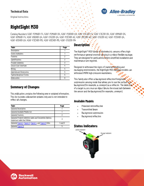
Technical DataOriginal InstructionsRightSight M30Catalog Numbers 42AF-P2MAB1-F4, 42AF-P2MAB1-D4, 42AF-P2RHB1-G4, 42AF-E1EZB1-F4, 42AF-E1EZB1-D4, 42AF-R1MAB1-D4,42AF-R1MAB1-F4, 42AF-R1RHB1-G4, 42AF-E1UZB1-G4, 42AF-P2CHB1-A2, 42AF-R1CHB1-A2, 42AF-E1UZB1-A2, 42AF-P2SHB1-G4,42AF-R1SHB1-G4, 42AF-P2CHB1-M5, 42AF-R1CHB1-M5, 42AF-E1UZB1-M4Summary of ChangesThis publication contains the following new or updated information.This list includes substantive updates only and is not intended toreflect all changes.DescriptionThe RightSight™ M30 family of photoelectric sensors offers high-performance general-purpose sensing in a robust flexible package.They are designed for applications where simplified installation andmaintenance are required.Designed to withstand the rigors of material handling andpackaging environments, the RightSight M30 standard models canwithstand IP69K high-pressure washdowns.This family also offers a background reflection/foregroundsuppression sensing mode that allows you to use the surface of abackground (for example, a conveyor) as a reflector. The detectionof a target occurs once an object blocks the visual path betweenthe sensor and the background (for example, conveyor).Available Models•Polarized retroreflective•Transmitted beam•Background suppression•Background reflectionStatus IndicatorsTopic PageDescription1Status Indicators1Features2Specifications2Product Selection3Sensor User Interface4Wiring4Approximate Dimensions5Typical Response Curves5Accessories6Topic PageUpdated Description1Updated Available Models list1Updated Features2Updated Product Selection table and Connection OptionsImportant table that follows3Updated Figure2, Figure3, Figure4, and Figure9 titles 4 and 5Updated Figure125Orange IndicatorGreen Indicator2Rockwell Automation Publication 42AF-TD001B-EN-P - June 2020RightSight M30 Technical DataFeatures•Maximum sensing distance-Background suppression without physicaladjustments (a): 400 mm (15.7 in.) and 600 mm (23.6 in.)-Background suppression with push button teach (a): 1.2 m (3.94 ft)-Background reflection with push button teach (a): 800 mm (31.5 in.)-Polarized retroreflective:10 m (32.8 ft) with 92-125 reflector -Transmitted beam:80 m (262.5 ft)•High powered light source for ease of alignment•360° highly visible user interface helps operators verify the proper operation, regardless of the sensor installation location•Background suppression performance helps minimize false detections due to highly reflective backgrounds•Dual Auto PNP/NPN helps streamline inventory by reducing the number of catalog numbers to stock•Push button lock helps prevent unauthorized operators from changing the sensor settings•Embedded IO-Link 1.1 communications protocol•Adjustable sensing ranges and response time via IO-Link provides additional flexibility to detect targets at longer or shorter distances depending on the application requirements.•IP67 and IP69K rated enclosure.Specifications(a)All models can be taught to detect targets up to 4 m (13.1 ft.) when using IO-Link to adjustthe response timeAttribute ValueCertifications c-UL-us and CE Marked for all applicable directivesVibration 10…55 Hz, 1 mm (0.04 in.) amplitude, meets, or exceeds 60947-5-2Shock30 g (1.1 oz) with 1 ms pulse duration per IEC 60947-5-2Ambient light immunity •Direct Illumination: 20,000 lux•Indirect Illumination: 5000 lux•Sunlight immunity; 108,000 lux User Interface Status indicators Green and orange light-emitting diodes (LED)Electrical Adjustments No physical adjustment. IO-Link adjustable Operating voltage •DC models: 10...30V DC, IO-Link: 18 (30V)•AC/DC models: AC: 24…250V AC/DC: 20…250V DC Current consumption 35 mA maxSensor protection DC: Reverse polarity and short circuit; AC/DC: Reverse polarity Discrete Output Response time •DC: 1 ms•AC/DC: 15 ms max Output type •DC: Dual Auto PNP or NPN •AC/DC: EM RelayLoad current •DC: 100 mA max•AC/DC SPDT: 10…30V DC: 3 A; 31…125V DC: 200 mA;24…250V AC: 3 AIO-LinkCommunications mode COM2Cycle time, min 2 ms Process data bit length 32 bits (4 bytes)Specifications 1.1Mechanical Housing material PBT Lens material PMMA Cover material Polysulfone Reliability DataTransmitted Beam and Polarized Retroreflective AC/DC MTTFd (hours)6548788.474T10d78.76Transmitted Beam and Polarized Retroreflective DC MTTFd (hours)9310986.965T10d111.9875Transmitted Beam Emitter AC/DC MTTFd (hours)24271844.66T10d291.9285467Transmitted Beam Emitter DC MTTFd (hours)24271844.66T10d 291.9285467Environmental Enclosure type ratingIP67 and IP69K per ISO 20653 rated enclosureOperating temperature -40…+70 °C (31…158 °F) (1)(1)The sensing range for all sensing modes can be reduced up to 20% when operatedbetween -40…-25 °C (-40…-13 °F).Connection type • 2 m (6.5 ft) cable •4-pin Integral M12 QD•4-pin M12 QD on a 150 mm (5.9 in.) pigtail•4-pin mini QD on 150 mm (5.9 in.) pigtail •5-pin mini QD on 150 mm (5.9 in.) pigtailRockwell Automation Publication 42AF-TD001B-EN-P - June 20203RightSight M30 Technical DataProduct SelectionSee https:///Sensors-Switches/Photoelectric-Sensors for additional details about the operation of the RightSight M30 in IO-Link mode.Sensing Mode Operating Voltage Light SourceSensing DistanceSensitivity Adjustment Output Function Output Type Cat. No.Background Suppression10...30V DC InfraredDefault setting:10...400 mm (0...15.7 in.)No physical adjustment. IO-Link teach: 4 m (13.1 ft) (1)(1)Sensor response time can be changed up to 75 ms to achieve distance of up to 4 m (13.1 ft). A higher distance between target and high reflectivity background may be needed whenoperating the sensors at distances greater than 2 m (6.6 ft).Light and dark operate Dual autoPNP or NPN42AF-B1MAB1-D4Default setting:10...600 mm (0...23.6 in.)No physical adjustment. IO-Link teach: 4 m (13.1 ft) (1)42AF-B1MAB2-D4Default setting:10...1.2 m (0...3.9 ft)Push button teach: 3 m (9.8 ft) IO-Link teach: 4 m (13.1 ft) (1)42AF-B1MAC1-D4Background Reflection10...30V DC Infrared0...800 mm (0...31.5 in.)Push button teach: 3 m (9.8 ft) IO-Link teach: 4 m (13.1 ft) (1)Light and dark operate Dual auto PNP or NPN 42AF-N1MAC1-D4Polarized Retroreflective10...30V DCVisible red0.025...10 m (0.03...33 ft)with 92-125 reflector No adjustment (IO-Link adjustable)Light and dark operate Dual auto PNP or NPN42AF-P2MAB1-D420...250V DC 24...250V AC No adjustment Light operate SPDT EM relay 42AF-P2RHB1-G4Dark operate 42AF-P2SHB1-G4Light and dark operate42AF-P2CHB1-A2Transmitted Beam10...30V DC Infrared0...80 m (0...262 ft)No adjustment (IO-Link adjustable)Transmitted beam emitter —42AF-E1EZB1-D420...250V DC 24...250V AC42AF-E1UZB1-G410...30V DC No adjustmentLight and dark operate Dual auto PNP or NPN 42AF-R1MAB1-D420...250V DC 24...250V ACLight operate SPDT EM relay42AF-R1RHB1-G4Dark operate 42AF-R1SHB1-G4Light and dark operate42AF-R1CHB1-A2IMPORTANTConnection Options (1): The following suffixes describe the available connection options:•D4: Describes an integral 4-pin DC micro (M12) quick-disconnect for DC models.•G4: Describes a 4-pin AC micro (M12) quick-disconnect on a 150 mm (6 in.) length pigtail on AC/DC models.•F4: Describes a 4-pin DC micro (M12) quick-disconnect on a 150 mm (6 in.) length pigtail on DC models.•A2: Describes a 2 m (6.6 ft) PVC cable.•M4: Describes a 4-pin mini quick-disconnect on a 150 mm (6 in.) length pigtail. Transmitted beam emitter only.•M5: Describes a 5-pin mini quick-disconnect on a 150 mm (6 in.) length pigtail on AC/DC models. Polarized retroreflective and transmitted beam receivers only.(1)Additional connection options may be available. See the ProposalWorks™ tool for available options by sensing mode.Table 1 - Standard I/O (Auto PNP/NPN) Operating Mode IndicationColorStatus Description GreenOFF Power is off ON Power is onFlash (6 Hz)Unstable light: 0.8 X <margin<1.5X Flash (1.4 Hz)Output short circuit protection active OrangeOFF Output de-energized ONOutput energizedTable 2 - IO-Link Operating Mode IndicationColor Status Description Green OFF Power is off Flash (1 Hz)Power is onOrangeOFF Output de-energized ONOutput energized4Rockwell Automation Publication 42AF-TD001B-EN-P - June 2020RightSight M30 Technical DataSensor User InterfaceThe green status indicator can also serve as a setup alignment aid. As the sensor is adjusted, • A flashing green indicator shows that the sensor has detected a margin of 0.8 X• A flashing green indicator and steady orange output indicator shows a margin greater than 1•Steady green and orange indicators show a margin greater than 1.5. This status means that the sensor is receiving at least 1.5 times the signal strength back from the target that is required to trigger an output signal.In general, it is desirable to have a higher margin to help overcome any deteriorating environmental conditions (dust build-up on the sensor lens). When aligning the sensor, the optimum performance can be obtained if this margin indicator is illuminated with the target in place.Table 3 provides indicator status in the RUN mode, during operation. The sensor is always in run mode except when being taught.WiringThe quick-disconnect connector is shown in Figure 1. The pin numbers correspond to the male connectors on the sensor.Figure 1 - PinoutsDC ModelsFigure 2 - Polarized Retroreflective(42AF-P2MAB1-F4 and 42AF-P2MAB1-D4)Light Operate and Dark Operate (Auto PNP or NPN)Figure 3 - Transmitted Beam Receiver (42AF-R1MAB1-F4 and 42AF-R1MAB1-D4)Light Operate and Dark Operate (Auto PNP or NPN)Figure 4 - Transmitted Beam Emitter (42AF-E1EZB1-F4 and 42AF-E1EZB1-D4)Table 3 - Connection TypesDescriptionCat. No. Suffix2 m (6.56 ft) cable-A24-pin DC micro (M12) QD on 150 mm (6 in.) pigtail -F4Integral 4-pin DC micro (M12) QD-D44-pin AC micro on 150 mm (6 in.) pigtail -G44-pin mini QD on 150 mm (6 in.) pigtail -M45-pin mini QD on 150 mm (6 in.) pigtail-M5Item DescriptionLED Disable For normal operation, the white wire needs no connection.To disable the light source, connect the white wire to +V.Frequency SelectFor normal operation, the white wire needs no connection.To change the emitter operating frequency, connect the black wire to +V. This feature is supported in future firmware revisions of the Transmitted Beam Receiver.IMPORTANTFor transmitted beam emitter only:Do not connect pin 2 and pin 4 for normaloperation. Unless a change in frequency is required when working with a receiver, these two pins remain unconnected when wiring the transmitted beam emitter sensor to anArmorBlock® I/O module.4-pin Micro (M12)Brown (1)Blue (3)Black (4)White (2)+V-VLight Operate (Auto PNP/NPN)Dark Operate (Auto PNP/NPN)Brown (1)Blue (3)Black (4)White (2)+V-VLight Operate (Auto PNP/NPN)Dark Operate (Auto PNP/NPN)Brown (1)Blue (3)Black (4)White (2)+V-VFrequency Select LED DisabledRockwell Automation Publication 42AF-TD001B-EN-P - June 20205RightSight M30 Technical DataAC/DC ModelsFigure 5 - Polarized Retroreflective and Transmitted Beam Emitter Light Operate (42AF-P2RHB1-G4 and 42AF-R1RHB1-G4)Figure 6 - Dark Operate(42AF-P2SHB1-G4 and 42AF-R1SHB1-G4)Figure 7 - Polarized Retroreflective and Transmitted Beam (42AF-P2CHB1-A2 and 42AF-R1CHB1-A2)Figure 8 - Polarized Retroreflective and Transmitted Beam (42AF-P2CHB1-M5 and 42AF-R1CHB1-M5)Figure 9 - Transmitted Beam Emitter (42AF-E1UZB1-A2 and 42AF-E1UZB1-G4)Approximate DimensionsFigure 10 - Integral M12 Connector [mm (in.)]Figure 11 - M12 Pigtail and Cable Models [mm (in.)]Typical Response CurvesFigure 12 - Visible Red Polarized Retroreflective — 10 m (32.81ft) Margin CurveFigure 13 - Visible Red Polarized Retroreflective — 10 m (32.81ft) Beam PatternTable 4 - UL508 Overcurrent ProtectionConductor Size Ampere Rating of the Overcurrent Protection, MaxAWG mm 2200.525220.323240.202260.131280.080.8300.050.5Red w/Black (1)Green (3)Red (4)Red w/White (2)(-V) L2(No Connection)Light Operate (+V) L1Red w/Black (1)Green (3)Red (4)Red w/White (2)(-V) L2(No Connection)Light Operate (+V) L1(+)˜(-)˜(+)˜(-) ˜Red w/Black (1)Not Used (3)Not Used (4)Red w/White (2)(-V) L2(+V) L1Sensing Distance [m (ft)]O p e r a t i n g M a r g i n 0.01(0.03)0.1(0.33)1(3.28)10(32.81)01020304050607080(13.12)(19.68)(26.25)(32.81)(39.37)Distance [m (ft)]D i s t a n c e [c m ](6.56)6Rockwell Automation Publication 42AF-TD001B-EN-P - June 2020RightSight M30 Technical DataFigure 14 - Infrared Transmitted Beam Emitter — 80 m (262.5ft) Margin CurveFigure 15 - Infrared Transmitted Beam Emitter — 80 m (262.5ft) Beam PatternAccessoriesFigure 16 - 30 mm (1.2 in.) Right Angle Mounting BracketFigure 17 - 18 mm (0.7 in.) Swivel/Tilt Mounting BracketCat. No. 60-2421Cat. No. 60-2439IMPORTANTFor polarized retroreflective sensors only: For optimal detection performance, when highly reflective targets pass between the emitter and the reflector, we recommend that you always install the rubber washer that is provided with the polarized sensor.(0.33)(3.28)(32.81)(328.08)Sensing Distance [m (ft)]O p e r a t i n g M a r g in(13.12)(19.68)(26.25)(32.81)(39.37)Distance [m (ft)]D i s t a n c e [c m ](6.56)Cat. No. 60-2649Cat. No. 60-2681DescriptionCat. No.4-pin DC micro, 2 m (6.5 ft) cordset 889D-F4AC-218 mm (0.7 in.) straight bracket 60-265618 mm (0.7 in.) right angle bracket60-265730 mm (1.2 in.) stainless steel mounting bracket 60-242130 mm (1.2 in.) swivel/tilt bracket 60-243918 mm (0.7 in.) swivel/tilt bracket60-2649Extended 18 mm (0.7 in.) swivel/tilt bracket 60-268176 mm (3 in.) diameter reflector 92-3947 mm (1.85 in.) diameter reflector 92-4784 mm (3.3 in.) diameter reflector92-12518 mm (0.7 in.) base mount, U-shaped protective bracket 60-BAF-US 18 mm (0.7 in.) base mount bracket, stainless steel 60-BAF-BM 30 mm (1.2 in.) nose mount bracket, stainless steel60-BAF-SM Aperture, 5 x 17 mm (0.2 x 0.67 in.) vertical slot, stainless steel 60-AAF1-VS Aperture, 5 x 12 mm (0.2 x 0.47 in.) horizontal slot, stainless steel 60-AAF1-HS Aperture, 2.5 x 12 mm (0.1 x 0.47 in.) horizontal slot, stainless steel 60-AAF2-HS Aperture, 5 mm (0.2 in.) diameter, stainless steel 60-AAF1-DS Aperture, 2.5 mm (0.1 in.) diameter, stainless steel 60-AAF2-DS U-shaped protective bracket60-BAF-US 18 mm (0.7 in.) base mount bracket, stainless steel 60-BAF-BM 30 mm (1.2 in.) nose mount bracket, stainless steel60-BAF-SM Aperture, 5 x 17 mm (0.2 x 0.67 in.) vertical slot, stainless steel 60-AAF1-VS Aperture, 5 x 12 mm (0.2 x 0.47 in.) horizontal slot, stainless steel 60-AAF1-HS Aperture, 2.5 x 12 mm (0.1 x 0.47 in.) horizontal slot, stainless steel 60-AAF2-HS Aperture, 5 mm (0.2 in.) diameter, stainless steel 60-AAF1-DS Aperture, 2.5 mm (0.1 in.) diameter, stainless steel60-AAF2-DSRockwell Automation Publication 42AF-TD001B-EN-P - June 20207RightSight M30 Technical DataFigure 18 - AperturesFigure 19 - Cat. No. 60-BAF-US 18 mm (0.7 in.) Mounting BracketFigure 20 - Cat. No. 60-BAF-SM 30 mm (1.2 in.) Bracket SideFigure 21 - Cat. No. 60-BAF-BM 18 mm (0.7 in.) Bracket BackCat. No. 60-AAF1-VS 5x17 mm (0.2x0.67 in.)Vertical SlotCat. No. 60-AAF1-HS 5x12 mm (0.2x0.47 in.) Horizontal SlotCat. No. 60-AAF2-HS 2.5x12 mm (0.1x0.47 in.)Horizontal SlotCat. No. 60-AAF1-DS 5 mm (0.2 in.) DiameterCat. No. 60-AAF2-DS 2.5 mm (0.1 in.)DiameterØØ4.5018.49 (0.73)(0.33)12.7 (0.50)33.02 (1.30)6.98(0.27)2 x 1.84 (0.07)9.73(0.38)2 x Ø 4.5 (0.18)12.7(0.50)4 x 4.57(0.18)6.35(0.25)22.2(0.87)22.86 (0.90)Ø 30.15 (1.19)3.17(0.12) Ref19.05 (0.75)44.45 ± 0.25(1.75 ± 0.01)0.79(0.03) Ref90°2 x 82°R 2.29(0.09)2 x 0.77 (0.03)45.72 (1.80)2 x Ø 3.83 (0.15)2 x 1.75 (0.06)17.78(0.70)30.48 (1.20)3.17(0.12) Ref2 x 0.79(0.31)15.16(0.60)90°2 x 82°R 2.29(0.09)Ø 18.49(0.73)8.89 (0.35)9.27 (0.36)6.98(0.27)8.25(0.32)8.89(0.35)19.05 (0.75)4 x R 4.57 (0.18)35.56 (1.40)30.48(1.20)0.79(0.03) RefPublication 42AF-TD001B-EN-P - June 2020Supersedes Publication 42AF-TD001A-EN-P - January 2019Copyright © 2020 Rockwell Automation, Inc. All rights reserved. Printed in the U.S.A.Rockwell Automation SupportUse these resources to access support information.Documentation FeedbackYour comments help us serve your documentation needs better. If you have any suggestions on how to improve our content, complete the form at rok.auto/docfeedback .Waste Electrical and Electronic Equipment (WEEE)Technical Support Center Find help with how-to videos, FAQs, chat, user forums, and product notification updates.rok.auto/support KnowledgebaseAccess Knowledgebase articles.rok.auto/knowledgebase Local Technical Support Phone Numbers Locate the telephone number for your country.rok.auto/phonesupport Literature LibraryFind installation instructions, manuals, brochures, and technical data publications.rok.auto/literature Product Compatibility and Download Center (PCDC)Get help determining how products interact, check features and capabilities, and find associated firmware.rok.auto/pcdcAt the end of life, this equipment should be collected separately from any unsorted municipal waste.Rockwell Automation maintains current product environmental information on its website at rok.auto/pec .Allen-Bradley, ArmorBlock, expanding human possibility, ProposalWorks, RightSight, Rockwell Automation, and Rockwell Software are trademarks of Rockwell Automation, Inc.Trademarks not belonging to Rockwell Automation are property of their respective companies.Rockwell Otomasyon Ticaret A.Ş. Kar Plaza İş Merkezi E Blok Kat:6 34752, İçerenkÖy, İstanbul, Tel: +90 (216) 5698400 EEE YÖnetmeliğine Uygundur。
LA120激光检测仪说明书

L A120激光检测仪说明书-CAL-FENGHAI.-(YICAI)-Company One1LA-120激光检测控制仪技术说明书E-mail:qclaser @ 目录一.LA-120激光外径检测控制仪性能参数二.激光外径检测仪工作原理三.仪器面板及说明四.仪器后板及说明五.仪器框图及说明六.仪器后板控制输入输出接线简图七.仪器操作方法八.显示内容、指示内容及输入输出内容说明九.仪器故障检查及解决方法十.装箱清单十一.装箱要求十二.附件及备件十三.附录一.LA-120激光外径检测控制仪性能参数测量范围: 0.5mm~40mm 40mm~120mm 静态测量精度: ±0.01mm动态测量精度: ±0.02mm ±0.03mm最快响应速度:秒最快分选速度: 120次/每分钟工作电压: 220V(+/–10%)50Hz功率: 50W环境温度: 50℃仪器显示方式: 5位LDD数据显示8位LED状态指示仪器操作方式:触摸式数字键盘输入仪器输入输出接口:大屏幕显示器的通讯接口翻板分选机构的开关控制输出七.仪器操作方法1.根据仪器框图正确连接电源和信号电缆。
2.接通电源,仪器显示型号LA-60数秒种后自动进入测量工作状态,显示直径测量值。
3.利用∧∨键可以切换显示内容(测量值、设置值、中间参数等,具体内容见详细说明)。
在显示测量值或中间参数时设置无意义,所以数字键无效;在显示设置值时可通过数字键0—9来修改设置参数,修改完成后要用写入键IN写入,见状态指示灯1闪烁指示后,表示修改被确认,否则修改无效。
4.仪器采用密码锁技术对重要参数进行保护。
一般情况下显示切换在常用内容之间循环,在编号码LDD指示“—”时可以写入密码,被确认后状态指示灯2点亮,指示显示切换转入所有可显示内容之间循环,完成设置和查询后可置复位键R回到常用内容循环状态,此时状态指示灯2熄灭。
两种显示循环方式的具体内容见详细说明。
保千里夜视仪说明书

夜视仪操作指南- 1 -请先阅读“夜视仪”在本手册中称为“本机”。
操作本机以前,请仔细阅读本说明书,并妥善保存以便日后查阅。
警告◆按照激光安全国际标准,本产品属于四类激光产品(CLASS Ⅳ)。
◆当激光灯正在工作时,10米以内切勿用眼睛逆光/直视或通过光学仪器观察,以免造成伤害。
◆在激光灯工作时,切勿在距离激光灯出光口5米内有任何可燃物,以免发生火灾。
- 2 -◆在激光灯工作时,2米以内,切勿用手或身体其它部分对激光阻挡,以免发生对皮肤伤害或火灾。
◆为减少发生火灾或触电的危险,请勿让本装置淋雨或受潮。
◆为减少火灾或触电的危险,请勿在本装置上放置如花瓶等盛有液体的物体。
◆切勿将本机暴露在火或类似的极热的环境下。
注意事项1. 请勿将产品置于不稳定的平面上进行测试、安装等操作,在进行操作前要确保机器摆放平稳、装配牢固。
2.运输及保管过程中要防止重压、剧烈振动和浸泡等对产品造成的损坏。
- 3 -3.接线时必须遵守各项电气安全标准,充电时请使用本机自带的专用充电电源或车载充电器充电,使用其他品牌充电器充电造成损失的本公司不负任何责任。
4. 不要在超出温度、湿度标准的环境下使用。
摄录仪使用温度为-10℃至45℃,湿度小于 90%。
5. 本产品内部并无用户可自行维修的部件,当机器有故障时,请勿轻易对机器进行任何修理操作,应先参照说明书查出故障,查不出原因则请专业人员维修。
有关维修工作,必须由我公司授权的维修网点进行维修或邮寄回本公司进行维修。
- 4 -目录请先阅读 (2)本机参数 (8)各部品名称......................................... - 12 - 准备工作..................................................... - 18 - 检查箱内附件..................................... - 18 - 安装示意图:............................................. - 21 - 背带安装............................................. - 21 -底座安装 (22)镜头盖、遮光罩安装 (23)三脚架安装......................................... - 24 - 快速操作指南............................................. - 25 - 充电..................................................... - 25 -开关机................................................. - 28 -按键操作说明..................................... - 29 -面板显示说明..................................... - 31 -基本操作说明..................................... - 33 -工作模式介绍..................................... - 35 -- 5 -录像/播放 ................................................... - 37 - 手动录像............................................. - 37 -播放..................................................... - 39 -快进/快退 ........................................... - 40 -音量加/减 ........................................... - 41 -电脑上播放......................................... - 43 - 特种功能使用及注意事项................................. - 44 - 自定义本机 ........................................................ - 45 - 主菜单设定................................................. - 46 - 摄像机设置................................................. - 49 - 录像系统设置............................................. - 53 - 影像设定..................................................... - 54 - 画质设定............................................. - 54 - 录像设定..................................................... - 58 - 预约时间............................................. - 59 -覆盖功能............................................. - 64 -档案长度............................................. - 65 -- 6 -录像模式..................................................... - 68 - 播放与删除视频文件................................. - 70 - 系统设定..................................................... - 72 - 时间设置............................................. - 74 -格式化................................................. - 74 -记忆卡信息......................................... - 75 - 简易故障排除及维修................................. - 78 - 注意事项............................................. - 81 - 配件清单..................................................... - 82 -- 7 -本机参数- 9 -- 10 -- 11 -- 12 - 各部品名称右选择菜单/确认 向下/缩小 模式/返回 左选择 向上/放大内置麦克风显示屏充电指示灯(内置)录像回放/暂停/删除/AE 录像回放/暂停(39页)删除(42页)AE调整(44页)底座开关机手动录像录像回放脚垫- 13 -录像键/强光抑制录像:(37页)强光抑制:(44页)开关机长按3秒钟进行开关机超声波感应器左挂绳柱摄像机激光光源右挂绳柱喇叭- 14 -麦克风插孔复位按钮激光开关耳机插孔DC IN插孔左把手:外置麦克风插孔。
高标准农田建设项目仪器之自动型虫情测报灯说明书
高标准农田建设项目仪器之自动型虫情测报灯说明书一、产品简介自动虫情测报灯是浙江托普仪器有限公司研制生产的新一代虫情测报工具。
该灯采用不锈钢材料,利用现代光、电、数控集成技术,实现了虫体远红外自动处理、接虫盒自动转换、整灯自动运行等功能。
该灯在技术设计方面采用32位ARM控制器结合液晶屏,使得操作界面更加简洁美观。
在无人监管的情况下,可自动完成诱虫、杀虫、收集、分装、排水等系统作业,并预留有与计算机相连的端口,可根据虫情测报灯标准化、可视化、网络化的需要随时将系统自动测得的环境气象资料输入计算机,对虫害的发生与发展进行分析和预测,为现代农业提供服务,满足虫情预测预报及标本采集的需要。
二、型号指南注:TPCB-Ⅱ-C、TPCB-Ⅲ-C、TPCB-Ⅳ-C为标准型,其他型号为定制型。
三、型号列表产品名称型号区别自动虫情测报灯 TPCB-Ⅱ-C 交流供电,红外处理,分天存放自动虫情测报灯T PCB-Ⅱ-C-1 交流供电,红外处理,分天存放,环境温湿度显示自动虫情测报灯T PCB-Ⅱ-C-2 交流供电,红外处理,分天存放,环境温湿度、风速、风向、光照度显示太阳能自动虫情TPCB-Ⅲ-C 太阳能(直流)供电,红外处理,分天存放测报灯太阳能自动虫情测报灯TPCB-Ⅲ-C-1太阳能(直流)供电,红外处理,分天存放,环境温湿度显示太阳能自动虫情测报灯TPCB-Ⅲ-C-2太阳能(直流)供电,红外处理,分天存放,环境温湿度、风速、风向、光照度显示交直流两用自动虫情测报灯TPCB-Ⅳ-C 交直流两用,红外处理,分天存放交直流两用自动虫情测报灯TPCB-Ⅳ-C-1交直流两用,红外处理,分天存放,环境温湿度显示交直流两用自动虫情测报灯TPCB-Ⅳ-C-2交直流两用,红外处理,分天存放,环境温湿度、风速、风向、光照度显示四、产品特点①整体采用不锈钢结构;②集成光控:白天自动关灯,夜间自动开灯;雨控:雨天自动排水,有效将雨虫分离;③利用远红外加热杀虫技术有效杀虫,虫体完整率大于95%;④红外处理仓温度控制:工作15分钟后达到85±5℃;⑤八个接虫器自动转换,虫体按天存放,避免混淆;⑥时段控制:可根据靶标害虫生活习性规律任意设置;⑦灯体结构可拆分,运输便利,安装方便;⑧防雷装置:能够有效防止雷击;⑨可根据客户需求选配环境温湿度、风速风向、光照度等传感器;五、技术参数电源交流185-265V/50HZ;直流24V太阳能蓄电池(12V/100AH两个);太阳能板135-150W;功耗待机功率<5W;最大功率<150W;灯管启动性能5S内启动绝缘电阻≥2.5MΩ诱虫光源20W黑光灯管(主波长365mm),可根据害虫种类选用不同波长的黑光灯外形尺寸TPCB-Ⅱ-C系列:800 mm×800 mm×2050 mm运输尺寸TPCB-Ⅱ-C系列:880 mm×880 mm×2250 mm外形尺寸TPCB-Ⅲ-C、TPCB-Ⅳ-C系列:800mm×800mm×2500mm运输尺寸TPCB-Ⅲ-C、TPCB-Ⅳ-C系列:880mm×880mm×2500mm单屏尺寸长445±2mm、宽210±2mm、厚4mm(撞击屏互成120度角)六、工作原理1.光控工作原理:当环境光照度连续一分钟≧4lux时,相关控制电路断开,测报灯处于待机状态——诱虫灯及加热管关闭、雨水通道开启;当环境光照度连续一分钟<4lux时,相关控制电路闭合,测报灯进入工作状态——诱虫灯、加热管及落虫通道开启。
Cadet 电子表面热器产品说明书

Vancouver, WashingtonUSAtested to UL standards/install/energyplusFor how-to videos or more information, please visit: Thank you for your purchase! Question or problem? Let us solve it with a single phone call, email or online chat! We’ll save you a trip back to the store!Phone: (855.223.3887)email: *****************************Live chat: (contact us)Cadet Customer Service120 v o l tsingle-pole breaker240 v o l tdouble-pole breaker• The multi-volt CE163T and CE083T Energy Plus heaters are equipped with a smart sensor that will auto adjust to your voltage supply.The CE162T can only be connected to 240 volts, and the CE168T can only be connected to 208 volts.If you are uncomfortable working with electricity, running electrical supply wire or installing a circuit breaker, please consult a licensed electrician. Make sure power to the heater is turned off at the main disconnect panel whenever doing any work on a heater. Serious injury or electrocution can result from electric shock.• CHECK YOUR BREAKER! If you’re replacing an existing heater, check the labels of the old heater and use the same voltage.Unanswered questions? Call our technical support team in Vancouver, Washington toll free at 855.223.3887 or outside the USA 360.693.2505WARNING: Connecting a heater to a voltage higher than what’s listed on its rating label will destroy the heater and could start a fire. A heater will not heat properly when connected to a voltage lower than what’s listed on its rating label.TOOLS REQUIREDTape MeasureStraight and PhillipsScrewdrivers1½" Wood ScrewsWire Strippers Wire Connectors ½" Cable Clamp ConnectorVolt Meter Drill and Drill BitsStud FinderA multi-purpose tool or something to cut your existing drywall or gypsum board.Hammer Z I R C O N INSTALLATION INSTRUCTIONS1. A ll electrical work and materials mustcomply with the National Electric Code (NEC), the Occupational Safe-ty and Health Act (OSHA), and all state and local codes.2. U se copper conductors only.3.D O NOT install the heater directly above bathtub or sink. DO NOT install in shower stall area. Cadet recommends installing your heater at least 2 feet (61 cm) away to prevent contact with water.4. H eater must be connected to a GFCIprotected branch circuit when in-stalled in a bathroom.5. H eater must be installed in a wallcan:Model CE - wall can model CC or CCSM 6. D O NOT install the heater in a floor, in the ceiling, below a towel bar,behind a door, or anywhere the air discharge may be blocked in any manner.7.T o reduce the risk of fire, do not store or use gasoline or other flam -mable vapors and liquids in the vi -cinity of the heater.8. C onnect grounding lead togrounding screw provided. Keep all foreign objects out of heater.9. E lectric heaters must be installedon a circuit dedicated to electric heaters, they cannot share a circuit with outlets, lights, or other appli-ances.10. C AUTION-High temperature, riskof fire, keep electrical cords, drap -ery, furnishings, and other combus-tibles at least 3 feet (0.9 m) from the front of the heater and away from the side and rear.PARTS OF YOUR HEATERModel:Volts:Watts:WARNING! TO A VOID ELECTRICAL SHOCKDisconnect power at circuit breaker before servicing. Do not operate without Vancouver, WA Mfg Date:Before pushing RESET button see Owner’s Guide for display fault codes and other troubleshooting information.3108579conforms to UL STD 202173built-in digital thermostatheater element fan andmotorhigh-temperature safety shutoff 3Install grillSTEP 5Attach grill with screws provided. Turn electrical power back on at the main disconnect panel. Wait 10 to 15 seconds for heater to power up before pushing any buttons. After a few seconds, if the heater has been properly installed, the display will flash and show room temperature. The default temperature setting in HEAT mode is 70˚F (21.1˚C). Proceed to OPERATING INSTRUCTIONS.of the heater and the wall can.4. Attach the heater assembly at top of the wall can with screw provided. Align digital display with grill cutout before tightening.120 Voltprolong the life of the heater, read the Owner’s Guide and follow the instructions. Failure to properly maintain the heater will void any warranty and may cause the heater to function improperly.LIMITED FIVE YEAR WARRANTY: Cadet will re-pair or replace any Energy Plus (CE) heater found to be defective within five years after the date of purchase.These warranties do not apply:1. Damage occurs to the product through improper installation or incorrect supply voltage;2. Damage occurs to the product through improper maintenance, misuse, abuse, accident, or alteration;3. The use of unauthorized accessories or unau-thorized components constitutes an alteration and voids all warranties. Refer to Cadet website or call customer service at 855.223.3887 or 360.693.2505 for list of authorized accessories and components.ment.5. In the event Cadet elects to replace any part of your Cadet product, the replacement parts are sub-ject to the same warranties as the product. The in-stallation of replacement parts does not modify or extend the underlying warranties. Replacement or repair of any Cadet product or part does not create any new warranties.If you believe your Cadet product is defective, please contact Cadet during the warranty period, for instructions on how to have the repair or replacement processed.Parts and ServiceVisit /parts-service for information on where to obtain parts and service.To register your product, visit /product-regist ration1. R oute the electrical supply wire from the circuit breaker to heater #1. Remove two knockouts and attach two sets of electrical supply wire with two cable clamp connectors (not included) leaving a mini-mum of 6 inches wire lead—one set from the circuit breaker, the other set to heater #2 (See Figure 5).More than one heater can be wired in parallel on the same circuit breaker (be sure to check national and local codes for safety requirements). Additional electrical supply wire and cable clamp connectors are required. The heaters must be in the same room.Maximum amperage you can put on one circuit breaker is limited to 80% of the circuit breaker capacity. 6CE168T 208 VoltCE162T 240 VoltCE163T/CE083T Multi-VoltNIGHT/AWAY MODE• MAX/MIN TEMPERATURE LOCK Program maximum and/or minimum tempera-ture settings as a child safety or tamper-proof option.MAXIMUM 86˚F (30˚C):• temperature.• HL • with 0. Your settings are saved.To change the lock temperatures, follow the same instructions.• temperature.FAN MODEStops heating, or circulates air without heat. • In HEAT mode, press . Fan runs at a low level until heater cools down. This lasts for 5 to 10 minutes.When fan stops completely, in display.• In FAN mode, press or to adjust fan speed.0. Your settings are saved.HEAT MODEDigital display shows room temperature, and the level of heat being output.Full PowerMedium Low Power˚F • ˚F (12.8˚C).• Fan runs at a low level until heater cools down. ThisClean heater at least every 6 months or as required. Do not lubricate motor.1. Turn off power at the main disconnect panel.2. Wait for the heater to cool.3. Remove grill.4. Wash grill with hot soapy water and dry.5. Blow air through the heating element with a hair dryer or shop vacuum on blow cycle.6. Clean the fan with a vacuum cleaner.7. Replace grill.8. Turn power back on at the main disconnect panel.Arepresentative.High-temperature safety shutoffAll Energy Plus heaters come with a built-in high-temperature safety shutoff that stops electricity flowing to the heater if it gets too hot inside. See TROUBLESHOOTING below if you’re experiencing problems with your heater.8Reduce-Reuse-RecycleThis product is made primarily of recyclable materials. You can reduce your carbon footprint by recycling this product at the end of its useful life. Contact your local recycling support center for further recycling instructions.Rev 12/3/18 #720065If you are uncomfortable working with electricity, running electrical supply wire or installing a circuit breaker, please consult a licensed electrician.©2018 Cadet Printed in USA。
EcoBlue 荷兰品质光学仪器说明书

™A NT I MI C R O B I AL PR O T E C T I ONL A Y E R EEC-1001EEC-1005 EEC-1057™ | S O L U C I O N E S D I G I T A L E S || E D U C A C I ÓN |FIC HA TÉC NI C AACC ESORI OS Y RECAM BIOSO C U L A R E SEAE-5571 Ocular de gran campo WF 5x/18 mm EEC-6010 Ocular HWF 10x/18 mmEEC-6010-M Ocular micrométrico de gran campo HWF 10x/18 mm EEC-6015 Ocular HWF 15x/12 mmEEC-6110 Ocular micrométrico HWF 10x/18 mm EEC-6099 Pareja de protectores de goma para ocular(1) Platina mecánica integrada con desplazamiento X-Y de 70 x 27 mm (2)Con alimentador/cargador de batería externo 100-240 V (3)Los modelos de polarización se suministran con una platina redonda de 129 mm y objetivos semiplanos e iluminación H-LED (espectro de luz similar al halógeno)(4)Modelo con objetivos semiplanosM O D E L O S E S TÁN DA R M O D E L O SMono Bino Trino4/10/40x objectives Objetivo S60x Objetivo S100x Platina mecánicaX-Y (1)LED NeoLED™Baterías (2)Polarización (3)EEC-1001•••EEC-1101••••EEC-1601••••EEC-1051•••••EEC-1151••••••EEC-1651••••••EEC-1152••••••EEC-1652••••••EEC-1053•••••EEC-1153••••••EEC-1001-P -HLED-S •••• (4)EEC-1601-P -HLED-S ••••• (4)EEC-1101-P -HLED-S ••••• (4)EEC-1002-P -HLED-S •••• (4)EEC-1602-P -HLED-S ••••• (4)EEC-1102-P -HLED-S ••••• (4)EEC-1003-P -HLED-S •••• (4)EEC-1603-P -HLED-S ••••• (4)EEC-1103-P -HLED-S••••• (4)O B J E T I V O S - 45 M M PA R F O C A L E SEEC-7004 Objetivo acromático 4x/0.10. Distancia de trabajo 37.5 mm EEC-7010 Objetivo acromático 10x/0.25. Distancia de trabajo 6.8 mm EEC-7020 Objetivo acromático 20x/0.40. Distancia de trabajo 2.0 mm EEC-7040 Objetivo acromático S40x/0.65. Distancia de trabajo 0.6 mm EEC-7060 Objetivo acromático S60x/0.85. Distancia de trabajo 0.185 mm EEC-7000 O bjetivo acromático S100x/1.25 inmersión en aceite. Distancia detrabajo 0.195 mmM O D E L O S D I G I TA L E SM OD E LOSMonocular Binocular Objetivos de 4x/10x/S40x Objetivo de S60x Objetivo de S100x Platina mecánica X-Y *LED NeoLED ™EEC-1005•••EEC-1105••••EEC-1607••••EEC-1055••••EEC-1155•••••EEC-1157•••••EEC-1657•••••* Platina mecánica integrada con desplazamiento X-Y de 70 x 27 mmEEC-1603-P-HLED-SEAE-9918EuromexMicroscopenbv•Papenkamp20•6836BDArnhem•TheNetherlands•T+31(0)263232211•****************•。
本说明书包含了英谷激光PULSE系列激光器的所有相关
苏州英谷激光有限公司SuZhou Inngu laser Co.,LtdTEL: 86-0512-******** FAX: 86-0512-********前言本说明书包含了英谷激光PULSE系列激光器的所有相关使用信息。
说明书中有以下两种警示标识,在阅读的过程中,请特别注意其后所提示的内容。
这个标志用来警示操作者可能面临着直接暴露在可见、不可见以及紫外辐射下的危险。
这个标志用来警示操作者,不当操作可能对操作者以及设备造成潜在的危险,并给操作员提供重要的指导。
警告!请在使用英谷激光器前认真阅读此安装操作手册,如有任何问题请直接联系英谷激光!目录第一章英谷激光器安全使用声明及注意事项1.1英谷激光器操作安全使用免责声明 (4)1.2英谷激光器安全特性 (4)1.3英谷PULSE系列激光器安全注意事项 (5)1.4英谷激光器包装及运输时的注意事项 (6)第二章英谷激光器控制面板信息及接口说明2.1前置显示调节面板详细介绍 (7)2.2后置接口定义详解 (8)2.3报警显示信息 (9)第三章英谷激光器信号控制3.1 GATE方式控制 (10)3.2外部TRIGGER+PWM方式控制 (10)第四章英谷激光器RS-232通信详解4.1RS232接口管脚说明 (11)4.2RS232通讯控制软件说明 (12)第五章英谷激光器操作说明5.1自动开机操作说明 (18)5.2手动开机操作说明 (21)第六章英谷激光器与外部信号控制板卡的连接6.1英谷激光器板卡控制方式 (22)6.2EzCad(金橙子)接线方式 (23)6.3SAMLight接线方式 (24)6.4 Markingmate PMC2接线方式 (25)6.5打标软件常见设置 (27)第七章英谷激光器常见使用规范及故障处理7.1环境部分 (29)7.2设备部分 (30)7.3激光器部分 (30)7.4激光器故障处理 (30)附录A 常用配件维修更换流程第一章英谷激光器安全使用声明及注意事项1.1英谷激光器操作安全使用免责声明请操作人员在使用英谷激光器前,必须认真阅读此安装操作手册,避免激光器对人体产生任何意外伤害。
奥林匹斯ESG-100E电子手术生成器产品说明书

ELECTROSURGICAL GENERATOROLYMPUS ESG-100A new dimension in electrosurgerySimply smart.Procedural solutions make the differenceInternational endoscopy specialists have assessed the clinical performance of daily electrosurgical appli c a t ions in gastroenterology and pneumology. Combined with Olympus’ Imaging and EndoTherapy products, this new electro s urgical generator offers procedural solutions that are suitable for state-of-the art endoscopies.→T heir conclusion: the Olympus ESG-100 is an easy-to-use and safe generator empowering existing and future EndoTherapy instruments.Simply smart.From the leader in flexible endoscopyRevolutionary imaging technologies such as HDTV and NBI emphasises Olympus‘ leadership in flexibleendoscopy for the gastrointestinal tract and respiratory systems. In order to offer the pro c edural solutionsthat today‘s endoscopists are looking for, Olympus has focused on delivering excellence in electrosurgery.In collaboration with a worldwide network of research centres, universities and hospitals, Olympus hasdeveloped the new Electrosurgical Generator ESG-100. This innovative product meets your needs as well asthe highest international quality standards. Its output power of up to 120 watts and a variety of monopolar andbipolar modes for cutting and coagulation support all electrosurgical procedures in flexible endoscopy.Simply smart.Highest safety meets outstanding effectivenessOlympus ESG-100 incorporates technical features that provide excellent effectiveness and highest safety incutting and coagulation during endoscopic procedures.Olympus’ Rapid Spark Technology TM features High Power Cut Support (HPCS) to achieve imme d iatespark ignition and Fast Spark Monitor (FSM) to optimise cutting procedures in various tissue structures.Always as much as necessary; never as much as possible.→T he results: reduced leakage currents, reproducible tissue effects and enhanced protectionof EndoTherapy instruments.Olympus’ Versatile Coagulation Technology TM enables fast and effective desiccation as well as soft anddeep tissue coagulation in monopolar and bipolar modes.→T he results: controlled haemostasis as well as effective coagulation of larger tissue volumeswith end-of-procedure detection and acoustic feedback.Simply smart.powerresistanceCutting modes to meet your needsMonopolar and bipolar continuous cutting modes with low, medium or high thermal effects in tissue.→T he innovation: monopolar intermittent cutting mode with two different speed settings.Coagulation modes to meet your needsOne monopolar soft coagulation mode with minimal sticking for controlled desiccation. Two monopolar forcedcoagulation modes for fast and effective haemostasis with low and high power capabilities.→T he innovation: two modes suitable for deep tissue denaturation. With acoustic feedbackand automatic end-of-procedure detection.powerHPCSCuttingHPCSCuttingCoagulationPulseCut slowPulseCut fastSpecifications Specifications Specifications, design, and accessories are subject to change without any notice or obligation on the part of the manufacturer.Postbox 10 49 08, 20034 Hamburg, Germany Wendenstrasse 14–18, 20097 Hamburg, Germany Phone: +49 40 23773-0, Fax: +49 40 Always a clear viewOlympus ESG-100 has been designed to work together with the new peristaltic pump AFU-100. The foot pedal of the generator can also be used to activate the pump. With its maximum flow of 600ml/min, this roller pump is useful to clean the treatment site through the endoscopes’ instrument channel and to flush through EndoTherapy instruments. The AFU-100 offers fast tube insertion, three programmable pre-set flow rates, as well as a variable flow rate and follows the easy-to-use concept of the ESG-100.One system made for youAn easy-to-use interface and an intuitive selection of output modes with the additional foot pedal button are clear advantages of the Olympus ESG-100. The result: ‘hands-free’ operation while performing advanced procedures requiring frequent changes of the output mode. The ergonomic design of every part of the system makes the Olympus ESG-100 very user friendly. Even suitable for beginners.The system fits well in all standard Olympus trolleys and carts. Its compact design meets the requirements for space saving medical devices and for an advanced workflow in today’s EndoSuites.Simply smart.Technical data Olympus ESG-100 High frequency 330 – 380 kHz Type, protection class CF, Class I Power supply 220–240V (WB991036), 100–120V (WB991046), 50/60Hz, 400VA Size (W ×D ×H) 295×375×115mm Weight, without footswitch 6.5kg Monopolar output Sockets ∅ 6mm A-cord Single/split neutral electrode 10mm 2-pins Cut 1/2/3 120W @ 500 Ohms PulseCut slow/fast 120W @ 500 Ohms SoftCoag 120W @ 100 Ohms ForcedCoag 1 50W @ 500 Ohms ForcedCoag 2 120W @ 500 Ohms Bipolar output Sockets 28.8mm 2-pins and ∅ 4/8 mm coaxial Cut 1/2/3 120W @ 500 OhmsSoftCoag 120W @ 100 Ohms RFCoag incl. RCAP 40W @ 100 OhmsOlympus AFU-100 Flow rate 10 – 270ml/min (Pump tube ID3.2mm) 20 – 600ml/min (Pump tube ID4.8mm)Pump head 4 rollers, detachable Type, protection class CF, Class I Power supply 100–240V, 50/60Hz, 60VA Size (W ×D ×H), incl. pump head 295×430×115mm Weight, without footswitch 5.6kg Ordering informationComponents Olympus ESG-100 (220–240V), including footswitch WB991036Olympus ESG-100 (100–120V), including footswitch WB991046Olympus AFU-100 (100–240V), including connection cable WB950167Footswitch for AFU-100 (optional) WB950242Pump tube ID3.2mm (15 pieces/box, sterile single use, length: 0.5m) WB920137Pump tube ID4.8mm (15 pieces/box, sterile single use, length: 0.5m) WB920138Order Number E 0429510 · 1.500 · 05/10 · P R。
超红与绿色LED光源设备说明书

Part NumberEmitting Color (Material)Lens TypeIv (mcd) @ 2mA [2] Viewing Angle [1]Min. Typ. 2θ1/2APHBM2012LSURKZGKC■ Hyper Red (AlGaInP)Water Clear15 30 *6 *15■ Green (InGaN)50 90 *50 *90120°DESCRIPTIONSThe Hyper Red source color devices are made with AlGaInP on GaAs substrate Light Emitting DiodeThe Green source color devices are made with InGaN on Sapphire Light Emitting DiodeElectrostatic discharge and power surge could damage the LEDsIt is recommended to use a wrist band oranti-electrostatic glove when handling the LEDs All devices, equipments and machineries must be electrically groundedFEATURES2.0 mm x 1.25 mm SMD LED, 0.45 mm max. thickness Low power consumption Wide viewing angleIdeal for backlight and indicator Package: 2000 pcs / reel Moisture sensitivity level: 3 RoHS compliantAPPLICATIONSBacklightStatus indicatorHome and smart appliances Wearable and portable devicesHealthcare applicationsATTENTIONObserve precautions for handlingelectrostatic discharge sensitive devicesPACKAGE DIMENSIONSSELECTION GUIDENotes:1. θ1/2 is the angle from optical centerline where the luminous intensity is 1/2 of the optical peak value.2. Luminous intensity / luminous flux: +/-15%.* Luminous intensity value is traceable to CIE127-2007 standards.APHBM2012LSURKZGKC2.0 x 1.25 mm SMD Chip LED LampRECOMMENDED SOLDERING PATTERNNotes:1. All dimensions are in millimeters (inches).2. Tolerance is ±0.1(0.004") unless otherwise noted.3. The specifications, characteristics and technical data described in the datasheet are subject to change without prior notice.4. The device has a single mounting surface. The device must be mounted according to the specifications.ABSOLUTE MAXIMUM RATINGS at T A =25°CELECTRICAL / OPTICAL CHARACTERISTICS at T A =25°CNotes:1. The dominant wavelength (λd) above is the setup value of the sorting machine. (Tolerance λd : ±1nm. )2. Forward voltage: ±0.1V.3. Wavelength value is traceable to CIE127-2007 standards.4. Excess driving current and / or operating temperature higher than recommended conditions may result in severe light degradation or premature failure.ParameterSymbolEmitting ColorValue UnitMin.Typ. Max. Wavelength at Peak Emission I F = 2mA λpeak Hyper Red Green - 645 515 - nm Dominant Wavelength I F = 2mA λdom [1] Hyper Red Green - 630 525 - nm Spectral Bandwidth at 50% Φ REL MAX I F = 2mA Δλ Hyper Red Green - 28 35 - nm CapacitanceC Hyper Red Green - 35 45 - pF Forward Voltage I F = 2mA V F [2] Hyper Red Green 1.5 2.2 1.75 2.65 2.1 3.1 V Reverse Current (V R = 5V) I R Hyper Red Green - - 10 50 μA Temperature Coefficient of λpeak I F = 2mA, -10°C ≤ T ≤ 85°C TC λpeak Hyper Red Green - 0.14 0.05 - nm/°C Temperature Coefficient of λdom I F = 2mA, -10°C ≤ T ≤ 85°C TC λdom Hyper Red Green - 0.05 0.03 - nm/°C Temperature Coefficient of V F I F = 2mA, -10°C ≤ T ≤ 85°CTC VHyper Red Green--1.9 -3.0-mV/°C ParameterSymbolValueUnitHyper RedGreen Power Dissipation P D 75 102.5 mW Reverse Voltage V R 5 5 V Junction Temperature T J 115115°C Operating Temperature T op -40 to +85 °C Storage Temperature T stg -40 to +85°C DC Forward Current I F 30 25 mA Peak Forward CurrentI FM [1]185 150 mA Electrostatic Discharge Threshold (HBM) -3000 450 V Thermal Resistance (Junction / Ambient) R th JA [2] 560 560 °C/W Thermal Resistance (Junction / Solder point)R th JS [2]425 450°C/W Notes:1. 1/10 Duty Cycle, 0.1ms Pulse Width.2. R t h JA ,R t h JS Results from mounting on PC board FR4 (pad size ≥ 16 mm 2 per pad).3. Relative humidity levels maintained between 40% and 60% in production area are recommended to avoid the build-up of static electricity – Ref JEDEC/JESD625-A and JEDEC/J-STD-033.TECHNICAL DATAHYPER REDGREENTECHNICAL DATATAPE SPECIFICATIONS (units : mm)REEL DIMENSION (units : mm)PACKING & LABEL SPECIFICATIONSREFLOW SOLDERING PROFILE for LEAD-FREE SMD PROCESSNotes:1. Don't cause stress to the LEDs while it is exposed to high temperature.2. The maximum number of reflow soldering passes is 2 times.3. Reflow soldering is recommended. Other soldering methods are not recommended as they mightcause damage to the product.PRECAUTIONARY NOTES1. The information included in this document reflects representative usage scenarios and is intended for technical reference only.2. The part number, type, and specifications mentioned in this document are subject to future change and improvement without notice. Before production usage customer should refer tothe latest datasheet for the updated specifications.3. When using the products referenced in this document, please make sure the product is being operated within the environmental and electrical limits specified in the datasheet. Ifcustomer usage exceeds the specified limits, Kingbright will not be responsible for any subsequent issues.4. The information in this document applies to typical usage in consumer electronics applications. If customer's application has special reliability requirements or have life-threateningliabilities, such as automotive or medical usage, please consult with Kingbright representative for further assistance.5. The contents and information of this document may not be reproduced or re-transmitted without permission by Kingbright.6. All design applications should refer to Kingbright application notes available at https:///ApplicationNotes。
GK-120框型光电说明书

框型光电说明书产品型号:GK-120版本型号:V1.11.产品简述GK-120框型光电传感器是利用镜面反射原理,将红外光布满整个框体检测区域。
当有微小半透明或不透明的小物体经过检测区域时,接收器收到的光强会减弱,得到的信号也会变弱,从而实现检测功能。
GK-120框型光电传感器具有高分辨能力,最高分辨率可以达到Φ3.5mm。
GK-120常用于检测小零件、金属或非金属部件的计数、冲压厂中监控工件的弹出或移除;产品图片:2.功能特征自准值学习功能:可根据不同的应用环境,自学习基准值,适应不同环境的应用;延时可调节:响应的释放时间或输出信号脉冲延时可调节为:0.1--150ms ;动/静态切换:用户根据需要可以选择为动态工作模式或者静态工作模式;输出常开常闭切换:输出信号可以切换为常开或常闭;灵敏度自适应调节:用户根据检测的物体大小或物体透明程度可以调节灵敏度;高分辨率:最高分辨率可达到Φ3.5mm;两路独立输出:一路NPN集电极开路输出、一路PNP集电极开路输出;3.规格参数4.接线图5.操作描述1、产品上电,棕色线接电源正极10~30VDC,蓝色线接电源负极,黑色线是NPN输出信号线,白色线是PNP输出信号线;2、产品自学习基准值,在产品初次使用或者更换使用环境时,产品需要重新自学习基准值,同时长按NO/NC键和S/D键2S,绿色指示灯闪烁,产品正在自学习。
绿色指示灯停止闪烁,自学习完成;(注:产品正在自学习时,检测区域不能有其他东西)3、输出常开/常闭切换,长按NO/NC键2S,绿色指示灯闪烁后,常开常闭切换完成。
有信号输出黄色指示灯亮,没信号输出黄色指示灯灭;4、动/静态工作模式切换,长按S/D键2S,绿色指示灯闪烁后,动/静态模式切换完成。
动态工作模式,绿色指示灯亮,静态工作模式,绿色指示灯灭;5、输出延时设定,按照DELAY旋钮旁边的刻度,根据需要调节DELAY电位器。
顺时针旋转,延时逐渐增大,逆时针旋转,延时逐渐减小。
LNTECH光电保护装置说明书

一.安全距离的计算………………………………………………………………………………20 二.安装位置的确定………………………………………………………………………………21 三.相邻安装时的注意事项………………………………………………………………………23 四.周围物体反射面的影响………………………………………………………………………24 五.安装配件说明…………………………………………………………………………………25 六.安装工具………………………………………………………………………………………31
2. 自检功能完善 电路设计采用冗余和自检设计,确保当光电保护装置自身出现故障时,不向所控制的电路发 送错误信号。
3. 可设置自保功能(自锁功能) 设置有自保功能的光电保护装置,在启动时,或者当遮光使压力机滑块机构停止运行后,再 恢复通光时,滑块机构不能恢复运行。要使滑块机构恢复运行,必须先按动“复位按钮”使 光电保护装置复位(即进入正常工作状态)。
光电保护装置
使用说明书
◆ 光电保护装置的使用关系人身安全,使用前请仔细阅读使用说明书 ◆ 说明书是指导用户正确安装、使用光电保护装置的重要文件,请代
理商、经销商、机床厂务必将使用说明书随光电保护装置交付用户
山东莱恩光电科技有限公司 SHANDONG LAIEN OPTIC-ELECTRONIC TECHNOLOGY CO.,LTD.
◆ 使用、检查与保养
一. 注意事项………………………………………………………………………………………59 二. 检查与保养……………………………………………………………………………………59
◆ 简单故障检修
一. 光电保护装置故障与机床故障判别…………………………………………………………60 二. 控制器故障及检修……………………………………………………………………………60 三. 传感器、发光器、受光器的故障及检修……………………………………………………60
昆山赛可特电子有限公司高分子导电膜作业说明书【模板】

昆山赛可特电子有限公司高分子导电膜作业说明书第一部分(总括)1. 目的为粗磨除胶/水平电镀工序建立临时的工作指引,在该工作指引下,将已完成磨披锋工序之制板,在除胶/水平电镀工序后经过电镀加厚线路铜及孔壁铜,达到内外层导通及铜厚满足要求之目的。
2. 应用范围粗磨除胶&水平直接电镀工序3. 职责和权限3.1 工艺室负责提供技术指导,工艺文件的编制,品质监督及监督操作员工按WI规范操作。
3.2 品质部人员负责仪器、仪表的校正、计量;PQA人员负责蚀板工序产品首检及抽检;FQA负责最终检查。
3.3 化验室负责分析药液,根据工艺条件发出药液调整通知,以维持药水浓度在控制范围内,并负责自动添加校正及控制;3.4 生产部主管负责培训及检查员工操作是否正确,并形成记录3.5 粗磨除胶连水平电镀工序负责日常操作、自检,及控制操作条件,并填写全线检查记录及粗磨除胶连水平电镀生产记录与药水添加消耗记录、磨板机操作记录。
按规定的周期时间及内容进行保养工作并填写水平电镀保养(或更换)记录;3.6 维修部负责应用于生产设备的维修、保养。
4. 定义4.1 膨松:利用溶剂渗入孔壁的树脂内,使其膨胀形成疏松的环氧树脂,为去钻污做准备。
4.2 除胶:将附着在孔壁上的钻污清除,使内层线路不会被钻污阻挡,而失去与其它线路的导通能力;4.3 中和:清洗孔壁表面的树脂氧化残余物及锰盐.微蚀:微蚀铜面层,出现新鲜铜层,加强-后续结合力。
4.4 整孔:整孔剂是一种高清洁能力的调整剂,它能有效的调整孔壁表面特性,使孔壁表面沉积一层薄膜,同时促进氧化槽中二氧化锰的沉积.4.5 氧化:在通过整孔后的孔壁上覆盖一层二氧化锰。
4.6 催化:通过与二氧化锰薄膜反应,在孔壁上聚合一层导电膜。
4.7 电解再生器:利用高锰酸钾再生器电解MnO42-再生出MnO4-4.8 氧化(活度)系数:高锰酸钾的氧化能力,一般用氧化系数表示。
4.9 拖缸:生产前使用非生产钻孔板进行生产,用以激发药水的活性。
- 1、下载文档前请自行甄别文档内容的完整性,平台不提供额外的编辑、内容补充、找答案等附加服务。
- 2、"仅部分预览"的文档,不可在线预览部分如存在完整性等问题,可反馈申请退款(可完整预览的文档不适用该条件!)。
- 3、如文档侵犯您的权益,请联系客服反馈,我们会尽快为您处理(人工客服工作时间:9:00-18:30)。
框型光电说明书
产品型号:GK-120
版本型号:V1.2
1.产品简述
GK-120框型光电传感器是利用镜面反射原理,将红外光布满整个框体检测区域。
当有微小半透明或不透明的小物体经过检测区域时,接收器收到的光强会减弱,得到的信号也会变弱,从而实现检测功能。
GK-120框型光电传感器具有高分辨能力,最高分辨率可以达到Φ2mm。
GK-120常用于检测小零件、金属或非金属部件的计数、冲压厂中监控工件的弹出或移除;
产品图片:
2.功能特征
自准值学习功能:可根据不同的应用环境,自学习基准值,适应不同环境的应用;延时可调节:响应的释放时间或输出信号脉冲延时可调节为:0.1--5s ;
动/静态切换:用户根据需要可以选择为动态工作模式或者静态工作模式;
输出常开常闭切换:输出信号可以切换为常开或常闭;
灵敏度自适应调节:用户根据检测的物体大小或物体透明程度可以调节灵敏度;高分辨率:最高分辨率可达到Φ2mm;
两路独立输出:一路NPN集电极开路输出、一路PNP集电极开路输出;
3.规格参数
4.接线图
5.操作描述
1、产品上电,棕色线接电源正极10~30VDC,蓝色线接电源负极,黑色线是NPN输出信号线,白色线是PNP输出信号线;产品上电后30秒内不可使用不得有物体从检测窗口通过,30秒后产品自学习基准值,基准值自学习完成后绿色指示灯闪烁提示,然后产品进入可工作状态
2、产品自学习基准值,在产品上电使用时或者更换使用环境时,产品需要重新自学习基准值,长按SET键2S,绿色指示灯闪烁,产品正在自学习。
绿色指示灯停止闪烁,自学习完成;(注:产品正在自学习时,检测区域不能有其他东西)
3、输出常开/常闭切换,长按NO/NC/SD键2S,绿色指示灯第一次闪烁后仍然按住按键直到绿色指示灯第二次闪烁后在释放按键,常开常闭切换完成。
有信号输出黄色指示灯亮,没信号输出黄色指示灯灭;
4、动/静态工作模式切换,长按NO/NC/SD键2S,绿色指示灯第一次闪烁后释放按键,动/静态模式切换完成。
动态工作模式,绿色指示灯亮,静态工作模式,绿色指示灯灭;
5、输出延时设定,按照DELAY旋钮旁边的刻度,根据需要调节DELAY电位器。
顺时针旋转,延时逐渐增大,逆时针旋转,延时逐渐减小。
6、灵敏度设定,按照SENS旋钮旁边的刻度,根据需要调节SENS电位器。
顺时针旋转,灵敏度逐渐减小,逆时针旋转,灵敏度逐渐增大。
6.产品尺寸图。