Alcatel 4400使用说明书
思科4400系列WLC快速使用指南
思科4400系列WLC快速使用指南目录关于本手册 (3)安全声明 (3)控制器介绍 (3)控制器状态灯 (4)WLC开箱与操作 (5)WLC组件 (5)需要的工具和信息 (5)初始化系统配置信息 (6)选择位置 (6)连接到WLC的Console口 (7)运行启动脚本和系统自检 (8)使用启动向导 (11)登录WLC (12)核实接口配置和状态 (13)连接网络(汇聚) (14)Model 4402 Controllers (14)Model 4404 Controllers (14)连接WLC服务端口(可选) (14)链接AP (14)安装电源模块 (14)准备工具 (15)安装VPN模块 (16)准备工具 (16)关于本手册本手册用来帮助您了解CIsoc4400系列WLC的安装和最小化配置。
主要包括以下WLC 型号: 4402-25, 4402-50, 4404-25, 4404-50, and 4404-100.安全声明使用前注意一下事项:•确保环境温度在32 to 104° F (0 to 40° C)•确保充足的供电.•确保电源接地.控制器介绍Cisco 4400系列控制器(WLC)为无线网络部署提供最高级别的性能和扩展性,并且保护网络中现有的投资。
作为无线网络的核心部分,控制器可以提供安全、干扰检测、射频管理、服务质量保障、无线漫游等功能,并可以和其他控制器、Cisco无线控制系统(WCS)、AP协同工作,以提供一个完善的无线网络方案。
为了更好地使用本文,我们假定您已经完成了无线网络的结构设计。
射频资源管理功能自动检测并配置网络中出现的AP。
4400系列WlCT包括两款型号4402和 4404。
4402有两个分布式千兆以太网接口,每个接口可以管理多达48个AP,尽管如此,Cisco建议为了保证带宽每个接口管理的AP数量不要超过25个。
4402-25和4402-50分别支持25和50个AP注册到WLC中。
alcatel网管操作规范
Alcatel网管数据配置规范一、新起网元数据配置。
(2)1.配置网元基本信息 (2)2.配置网元NSAP地址 (3)3.将新建网元收到1354RM网管上 (5)二、物理连接数据配置。
(7)三、保护子网数据配置。
(9)1.SNCP保护的建立 (9)2.MSP-SPRing保护的建立 (10)3.1+1MSP保护的建立 (12)四、Trails数据配置。
(13)五、SDH数据配置。
(14)1.2M、34M、45M业务数据配置。
(14)2.155M业务数据配置。
(16)3.ETH业务数据配置。
(17)六、ISA板业务配置。
(21)1.1353NM1,NM4上监控ISA板方式 (21)2.1353NM2,NM3上监控ISA板方式 (23)一、新起网元数据配置。
1.配置网元基本信息在相应1353NM子图上选择Declarations→Create→NE…在弹出的对话框中填入相应的选项:Fimily:产品系列,一般电信所使用的产品都在Omsn序列中可以找到。
Type:产品类型里面用来选择产品型号,如1642EM、1660SM等设备。
Release:产品版本信息,可以和工程督导核实,取得设备的版本信息。
User Label:所起网元的名称,此名称应与资源系统中的网元名称进行核对,确保一致。
Locatin Name:场所名称,用拼音描述网元名称。
注意每个字的首个拼字字母大写。
其他选项不填然,后选择Apply键。
会在相应子图上看到所创建的网元。
2.配置网元NSAP地址选中刚才新建的网元单击右键选择,Set Addresses NE Address…在弹出的Address菜单中填入从工程督导处取得的相应得NSAP地址如下图:填完后选择Apply。
然后选择所创建的网元右键选择Supervision Align up在所弹出的Supervision对话框中选择Apply,如果配置正常可将该设备提到监控上来。
4400系列电源包安装和操作说明书
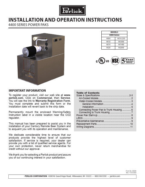
PERLICK CORPORATION 8300 W. Good Hope Road, Milwaukee, WI 53223 • 800.558.5592 • MODELS 4400 Series 44044414-23044104410W 44144414W 44204420WCUSINSTALLATION AND OPERATION INSTRUCTIONS4400 SERIES POWER PAKSIMPORTANT INFORMATIONTo register your product, visit our web site at . Click on Commercial , then Service . You will see the link to Warranty Registration Form . You must complete and submit this form or the installation date will revert back to the ship date.Permanently mount the enclosed Warning/Safety Instruction label in a visible location near the CO2 regulator.This manual has been prepared to assist you in the installation of your Century Remote Beer System and to acquaint you with its operation and maintenance. We dedicate considerable time to ensure that our products provide the highest level of customer satisfaction. If service is required, your dealer can provide you with a list of qualified service agents. For your own protection, never return merchandise for credit without our approval.We thank you for selecting a Perlick product and assure you of our continuing interest in your satisfaction.Table of ContentsSizes & Specifications ............................................2-3 Air-Cooled Models .................................................2 Water-Cooled Models ............................................3 General Information ..........................................4 Installation ........................................................5 Connecting Power Pak to Trunk Housing ..............6 Connecting to Trunk Housing ................................7Power Pak Start-Up ...................................................8LEDS .........................................................................9Preventative Maintenance .........................................9Replacement Parts ..................................................10Wiring Diagrams (11)Form No. Z2020Rev. 11.30.2022(Ground, Neutral, Hot-Power, Hot-Power)AC: 115 - 208/240v, 60 HZ, Split Single PhaseC US(Ground, Neutral, Hot-Power, Hot-Power)AC: 115 - 208/240v, 60 HZ, Split Single PhaseCUSPRODUCT DESCRIPTIONPower Paks have always been an integral part of a Perlick Century Beer System. The 4400 Series Power Pak product line has been expanded to satify longer beer runs. A Power Pak circulates coolant solution (food grade propylene glycol with distilled water) fromwalk-in cooler to the dispensing station(s) and back,maintaining the desired dispensing temperature at the faucet. The 4400 series Power Pak incorporate a 1/3 hp ball bearing, maintenance free motor with a 100 gallon per hour 150 psig positive displacement pump for optimum performance. The 4400 series Power Pak product line employs a direct expansion form of refrigeration increasing the units’ efficency aswell as making the units more compact. These unitsalso employ an electronic temperature control with digital readout. This state of the art control controlsthe performance of the unit as well as giving theuser a visual indication of the how the unit is workingas well as giving the user a visual indication of the how the unit is working as well as early indication if something may be going wrong through the use of internal alarms.AccessoriesPower Cord KitC2296A-20--12/3 Cord, 20A, Nema Plug 5-20P, Dedicated Circuit Models - See above electrical specificationsPower Pak Racks61790, 61790+1, 61790+2 - All ModelsPower Pak Wall Mounting BracketsFor Models 4404 & 4410 onlyCoolant Solution-63299-1One gallon Perlick Coolant solution, 30% DowFrost HD/70% Distilled Water Coolant Connector Kit 63335 - All Models Leg Set - All Models57782 . . . Set of four, 5 3/4”-71/2” adjustable legsPump Kits4430 - Pump kit, 115V, 6.1 A, 100 gph, 130 psigModels 4410, 4410W4431 - Pump kit, 115V, 5.6 A, 100 gph, 130 psig Models 4414, 4414W4432 - Pump kit, 230V, 2.8 A, 100 gph, 130 psig Models 4414-230, 4420WARNING: California Prop 65 NoticeThese products may expose you to chemicals i ncluding Chromium, which are known to t he state of California to cause cancer and b irth defects or other reproductive harm. For more information on whether a product in this list contains these chemicals, please refer to the specific product page at . Or to find out more about Prop 65, go to .4400 SERIES POWER PAKS - INSTALLATIONOperation/Installation ManualINSTALLATIONIMPORTANT SAFETY WARNINGS!• Follow all National and Regional Codes.• Read Installation and Operating Instructions carefully before attempting to install, operate or maintain the product.• Protect yourself and others by observing all safety information.• Electrical hazards exist and can cause injuries if not serviced by properly trained personnel.• Failure to comply with instructions could result in personal injury and/or property damage!• Retain instructions for future reference.• Never operate the circulating pump without coolant in the reservoir.NOTE: Air-cooled Power Paks must be installedin areas with adequate ventilation to maintain ambient temperatures of less than 105°F to achieve optimum performance and satisfy warranty requirements.INSTALLING THE POWER PAKPrior to installing a 4400 Series Power Pak, it isimperative that the method of connecting it to theelectrical service has been determined. Ensure thatthe electrical service to power the Power Pak willhandle the load requirements. Perlick has a PowerCord specifically designed for a Power Pak, which has a RLA of 16 amps or less, and a MCA of 20 amps orless. All units with RLA greater than 16 amps and aMCA of greater than 20 amps should have the Power Pak hard-wired to electrical service.ALL MODELS• Determine the ideal placement of the Power Pak.Locate the connection point to the truck housingand place the Power Pak as close to this point aspossible. NOTE: If the Power Pak is to be located on top of the walk-in cooler, it is imperativethat proper ventilation is provided to preventsystem failure due to overheating. Inadequateventilation will void warranty.• Place the Power Pak and Ensure that it is level to provide proper overflow protection. REMINDER: Allow a minimun of six inches of clearace on the louvered ends of the cabinet for proper airflow. Allow accessibility room on the top of the cabinet for serviceability.• Remove the top panels (2).• Ensure Power Switches for Condensing Unit and Pump(s) are in the OFF position. Make the electrical connections per ther illustrations. NOTE: Electrical circuit shold be a dedicated circuit for use only with the Power Pak. The circuit should be sized in accordance with the electrical requirements of each unit as well as in compliance with all National and Local Codes.• Plumb overflow port to a suitable reservior/drain.WATER-COOLED MODELS• In addition to the above installation instruction:• Care should be exercised in locating the PowerPak so that the unit will never be exposed to temperatures below freezing.• If the Power Pak is installing more than 5 feet higher than the remote outlet drain point (i.e., location of the floor drain) of the condenser, a vacuum breaker or open vent line should be provided to prevent the discharge line from creating a partial vacuum condition in the condenser water system.• If a water-circulating pump is used it should beplaced on the water supply side of the condenser, so water is being pushed through the condenser.• A potable water supply is required aswell as a drain or reclamation system. Make water supply connection to fitting labeled as the water inlet. Make outlet connection to fitting labeled as the water outlet connection. Both the inlet and outlet fittings supplied with the Power Pak are 1/2” Quick Connect fittings.• This equipment when equipped with a water-cooledcondenser, connected to a portable water supply system is to be installed with adequate backflow protection to comply with applicable federal, state and local codes.(Backflow protection not included.)CONNECTING POWER PAK TO TRUNK HOUSING 400 Series Power Paks require rigid fittings with a minimum pressure rating of 150 psig. Use Coolant Connector Kit #63335 to connect Power Pak to Trunk Housing.• Inspect pump outlet port for debris. Insert barbed fitting #63307 into pummp outlet port.• Inspect Glycol Return Manifold inlet for debris.Insert barbed fitting #63307 into return manifold inlet port.• Cut supplied coolant tubing, #54588, to required length to reach from Power Pak to Trunk Housing connection point.• Cut tubular insulation sleeve, #C12700, in half and install over previously cut coolant tubing.• Take Oetiker clamps, #54871-210, and install over coolant tubing ends.• Push coolant lines, one each over pump outlet barbed fitting #63307 and return manifold barbed fitting #63307.• Position Oetikers over barbed fitting and clamp securely.• Slide tubular insulation sleeves tightly against connection points. Use insulation tape as necessary to ensure an air tight seal to prevent excessive heat gain or condensation problems.• Drill a 3-1/2” diameter hole in walk-in cooler to accommodate coolant lines.• Install insulation donuts over hole (both inside and outside of cooler walls.• Slide large insulation sleeve, #57478, over remaining coolant tubing exposed to warm air conditions including inside walk-in cooler from Power Pak to Trunk Housing connection point. Seal and tape all seams to prevent excessive heat gain or condensation problems.• Slide coolant lines through 3-1/2” donut hole previosly cut in walk-in cooler wall.• Position Trunk Housing coolant lines and Coolant Connector kit lines in horizontal position, to alleviate condensation runoff into Trunk Housing.• Cut Trunk Housing coolant lines with tubing cutter to ensure clean burr free ends.• Take Oetikers clamps #54871-210, and install over coolant connector kit tubing ends.• Slide coolant connector kit tubing over the trunk housing coolant lines and secure using the Oetikers.• Complete the insulation process by ensuring that all coolant lines are well insulated including all seams to prevent excessive condensation and heat gain.• Seal donut hole to ensure an air tight seal to prevent walk-in cooler problems as well as condensation. CONNECTING TRUNK HOUSING COOLANT LINES TO DISPENSING HEAD• Position the trunk housing so that beverage lines can be connected with a minimum cutting.• Split trunk housing approximately 12 inches from the end to allow working room for the connections.• Cut and deburr copper coolant lines coming from trunk housing and dispensing head. Stagger the lengths.• Connect trunk housing coolant lines to dispensing head coolant lines using clamps, hose and 3/8”x 1/2” union, included in Head connecting kit, #63486. Ensure that coolant lines are fully clample to guarantee a leak free connection.SYSTEM START-UPUse only Perlick Approved Coolant Solution, #63299-1, all other solutions and mixtures will void the Perlick warranty. The Coolant Solution has been pre-mixed for optimum performance and wear protection. The Power Pak resevoir holds approximately 1.75 gallons of solu-tion. It takes approximately 1 gallon of Coolant Solution to fill every 60 feet of Perlick Trunk Housing.• Never operate the circulating pumps without coolant in the resevoir.• Fill Power Pak resevoir with Perlick Coolant Solution.• Turn condensing unit switch and pump switch to the ON position. Coolant solution level will begin to drop in resevoir.• Continue adding Perlick Coolant Solution until no air bubbles are apparent from the Coolant return line. NOTE: Never allow for the Coolant level in the resevoir to drop below the heat exchanger tube inlet. Allowing the level to drop below the inlet will allow air into the lines.• Fill Power Pak reservoir until both the return line fitting port and the overflow tube port are submersed under Coolant Solution. Watch return line fitting port for additional Coolant Solution may need to be added.• Thoroughly check all field connection points for leaks.• Monitor Power Pak Temperature read-out to ensure Power Pak is working properly. Dependent on length of trunk housing run(s) and surrounding ambient conditions, these factors will determine how long it takes for the Power Pak to cut-out on the temperature control. DIGITAL TEMPERATURE CONTROLLERThe 4400 Series Power Pak comes equipped with a Factory Programmed Electronic Thermostat with display. The Thermostat has numerous factory settings, which should never be adjusted or tampered with to ensure proper operation of the Power Pak. The Thermostat has been factory programmed to cut-out at 30°F with a hysteresis/differential of 4°F.Front Panel Commands–Normal OperationSET:To display target set point.DEFROST:To start a manual defrost. (This feature is avail-able, however, the parameters for actuation are pro-grammed, such that, no defrost is available).Front Panel Commands–Programming Mode SET:Selects a parameter or confirms an operation.UP ARROW:Browses the parameter codes or increases the dis-played value.DOWN ARROW:Browses the parameter codes or decreases the dis-played value.Meaning of LEDSLED MODE FUNCTION SNOWFLAKE ON CompressorEnabled SNOWFLAKE FLASHING Programing Phase (flashingwith DEFROST) Anti-short cycledelay enabled DEFROST FLASHING Programming Phase (flashingwith SNOWFLAKE) Drip time inprogress DISPLAY MESSAGE MEANINGSMESSAGE MEANINGPOF Keyboard is locked out. Noparameters can be adjustedwithout unlocking the keyboard. ALARM MEANING ACTIONEE Data or Consult Factorymemory failureP1 Room probe Numerous - seefailure note 1NOTE 1: Faulty probe, loose connection, broket wire. (Power Pak will continue to operate with a faulty probe. The controller has been factory programmed to continue operation with the compressor cycling on and off in 5 minute intervals.How to see the SETPOINT• Press and immediately release the SET key: the display will show the Set point value.• Press and immediately release the SET key or wait for 5 seconds to display the probe value again. How to change the SETPOINT• Press and hold the SET key for more than 2 seconds to change the Set point value.• The value of the set point will be displayed and the SNOWFLAKE LED starts blinking.• To change the Set value, press the UP or DOWN ARROWS, dependent on the new set point value.• To memorize the new set point value, press the SET key again or wait 15 seconds.WARNING:IF MESSAGE OR INFORMATION SHOWN ON READOUT IS UNFAMILIAR, ALLOW CONTROL TO SIT FOR A MINIMUN OF 15 SECONDS AND CONTROLLER SHOULD RETURN TO DISPLAY PROBE TEMPERATURE.Perlick is committed to continuous improvement. Therefore, we reserve the right to change specifications without prior notice11Form No. Z2020Rev. 11.30.2022Wiring Diagram For 414-230, 4420, AC115 - 208/240, 60 HZ Power Paks (4 Wire AC Power Source Required)Wiring Diagram For 4404, 4410, 4414 115V Power PaksForm No. Z2020Rev. 11.30.2022 PERLICK CORPORATION 8300 W. Good Hope Road, Milwaukee, WI 53223 • 800.558.5592 • 。
west 4400 设置手册
1200~9600 WEST ASCII
MODBUS 无校验
MODBUS 无校验
MODBUS 无校验
通讯地址 5 6 Address 冷端补偿 7 CJC
WEST ASCII 1-99 MODBUS 1-255
启动
禁止
密码个数 密码 8
Locks
LockCode Lock P Lock C
HwDefine
同时下排显示窗口会显示当前仪表的硬件代码 硬件代码和含义如下
用上升/下降键调整代码的数值 调整后按 MODE 键确认
3 数字输入/事件输出模块的设置 在显示硬件代码的情况下 按功能键 信息窗口显示
Ext Optn
下排窗口显示下面四者之一
无外部选件 有数字输入模块 有事件输出模块 用上升/下降键可调整设置 调整后按 MODE 键确认
4400 设置手册
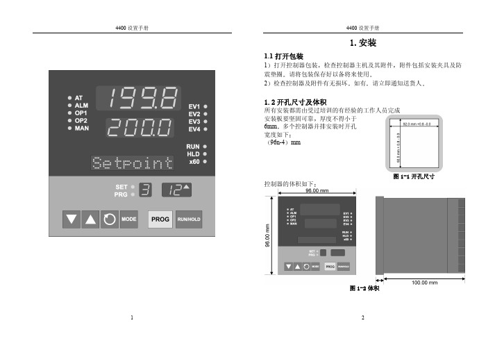
2.硬件配置及内部跳线
2.1 硬件位置
掉电后将控制器从表壳中取出 通过加入相应的选件模块及改变仪表中 CPU PCB 板及 PSU PCB 板上跳线端子的位置 可以改变硬件配置 CPU PCB 板 PSU PCB 及各种选件模块的位置如下
图 2-1 控制器内部结构
2.2 各硬件模块的安装步骤如下
输入类型表
代码 1127 1128 1227 1228 1415 1416 1417 1418 1419* 1420 1525 1526 1541 1542 7220* 7221 2229 2230 2231 2251 3413
类型 K K K K L L L L L L B B N N RTD RTD RTD RTD RTD RTD
程 序 升 温 设 Seg Mode 定
Alcatel OXE 4400基本安装手册

ALCATELA4400用戶培養訓練資料目錄1. 4400交換機機架簡介 (3)2. 4400交換機功能板簡介 (4)3. 4400交換機系統命令 (6)4. 4400交換機系統數據管理 (7)5. mgr 管理工具 (8)6. 分機管理 (9)7. 組管理 (12)8. 中繼管理 (14)9. 號碼編譯 (19)10. 類別管理 (22)1. 11. 用戶數據備份 302.3. 4400交換機機架簡介左圖為4400機架ACT 是用於插交換機功能板的分架。
ACT編號從0開始(如︰ACT0、ACT1)。
4400有兩種ACT,ACT14和ACT28。
ACT14有14個槽口,可插14塊功能板(如左圖的ACT1);ACT28有28個槽口,可插28塊功能板(左圖中的ACT2)。
4. 系統有固定的設備號(即物理位元址),設備號由ACT號、槽口號和功能板上的電路號組成(如︰ACT0上的第5槽口的UA32板上的第一個埠的設備號為0-5-0,ACT1上的第11槽口的UA32板上的最後一個設備號為1-11-315.4400交換機功能板簡介CUP-3、CUP-5 ( 主控板(板上有CPU、硬碟、內存條等主控設備)Z12、Z24 ( 類比用戶板(板上有12個或24個類比用戶埠,通過交換機後板電纜經配線架接普通電話機)UA16、UA32 ( 數字用戶板(板上有16個或32個數字用戶埠, 通過交換機後板電纜接ALCATEL的數字設備,如︰4004話機、4010話機、4020話機、4035話機、4048話務台及其他數字設備)NDDI ( 類比中繼板(板上有8個類比中繼埠, 透過交換機後板電纜接電信中繼)PRA2 ( T2數字中繼板式(板上有30個T2數字中繼通道, 透過交換機後板電纜或同軸電纜接電信中繼)VG ( 語音板(板上可插閃存卡,提供系統的語音提示及保留音樂)SUVG ( SU語音板(板上可插閃存卡,提供系統的語音提示及保留音樂,並提供雙音頻接收功能)MMSFD ( 軟驅板(板上有1.44M軟驅,透過軟驅可對系統進行數據備份)INTOF ( ACT分架介面板(各ACT分架透過此板與主ACT-CPU分架進行聯接)GPA ( 功能輔助板(提供29方會議功能,並可插閃存卡,提供系統的語音提示及保留音樂或雙音頻接收)VPS35 ( 語音信箱板(提供系統內置語音信箱服務功能)DECT4 ( 內部移動電話板(提供內部移動電話功能)BRA2 ( T0/S0介面板(板上有8個T0/S0埠,透過後板電纜接2B+D中繼和用戶)PCM2 ( PCM數字中繼板(板上有30個PCM數字中繼通道, 透過同軸電纜接電信的中國一號中繼)EMTL ( Tie-Line中繼板(提供Tie-Line組網功能)LIOE ( IP介面板(提供系統IP電話介面及其它IP介面)LIOB ( DDN介面板(提供64K/128K DDN中繼介面)IO2 ( 輸入輸出板(提供系統額外的輔助介面)6. RT2 ( 遠端ACT分架介面板(遠端ACT分架透過此板與主ACT分架進行聯接)7.4400交換機系統命令登錄系統命令和密碼login: mtclPassword: mtcl退出系統命令a4400a> exit系統複位命令◆a4400a> shutdown ih慎用,系統將停機後重新啟動。
阿尔卡特4400方案书

A4400交换机介绍1 概述现代通信走过了数字化、综合化、光纤化的道路后,正向智能化、宽带化、个人化的方向发展。
为了适应当今通信领域高速发展的需要,上海贝尔阿尔卡特业务通信系统有限公司于1998年10月28日推出了新一代通信产品AlcatelOmniPCX4400(A4400)程控交换机系统,AlcatelOmniPCX4400是为了满足集语音、数据及图象为一体的最新多媒体的通信平台,其结构一开始就是为平滑引入ATM技术而设计的。
它独特的水晶体结构技术可使系统内部集成所有的现代电信业务,并能提供宽带交换能力,其通用性和开放性既能作为各类信息的传输和交换平台,又能以信息交换服务器的方式融入广域网中。
AlcatelOmniPCX4400根据以下原则设计:语音、数据和图像以相应的服务质量进行交换模块化结构且能满足未来发展需求满足所有各类内部拓扑结构的需求新结构具有ATM兼容能力AlcatelOmniPCX4400新一代综合业务交换平台,包容了现在及今后十年的语音、数据、图象通信的发展需求,国际权威通信评测结构把AlcatelOmniPCX4400誉为真正的、新一代的通信服务器。
软硬件的模块化设计并以客户机/服务器的结构为各类用户提供了最灵活的最方便的服务,并广泛采用了各类国际通用标准,符合UnixSystemV标准,适合EthernetTCP/IP标准,PABX组网采用QSIG标准,CSTA标准用于CTI应用,为用户的自行开发应用提供了最佳的平台。
AlcatelOmniPCX4400的客户机/服务器结构阿尔卡特A4400水晶体结构技术的主要特点根据接入模式,每一条链路都由阿尔卡特特殊设计的功能强大的元件来进行管理,它称之为C1电路对于窄带应用来讲,AlcatelA4400在各块板之间提供8Mbytes链路(同样的链路也可支持速率达到622MBit/s的ATM宽带应用)。
发送:每个接口同时分配信息和信令通道给所有链路(发散模式类似于以太网的方式)接收:每个接口接收来自其他接口发送的所有信道,并且选择它所需要的信息。
4400手册
4400 安装手册
Honeywell
4400 安装手册
没使用
连接主机 黑 黄线
电源输入 7-24V AC 或 DC
辅助输出 +12VDC +5VDC 地 +12VDC +5VDC 地
+12VDC(P4 端)
输出类型选择 断开:LED 闭合:继电器
+5VDC(P4 端)
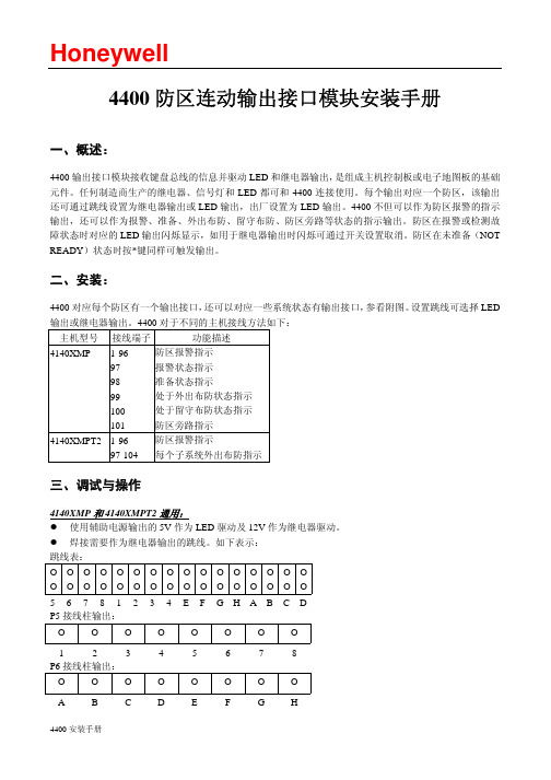
4140XMPT2 1-96 97-104
防区报警指示 每个子系统外出布防指示
三、调试与操作
4140XMP 和 4140XMPT2 通用: z 使用辅助电源输出的 5V 作为 LED 驱动及 12V 作为继电器驱动。 z 焊接需要作为继电器输出的跳线。如下表示: 跳线表:
OOOOOOOOOOOOOOOO OOOOOOOOOOOOOOOO
Honeywell
4400 防区连动输出接口模块安装手册
一、概述:
4400 输出接口模块接收键盘总线的信息并驱动 LED 和继电器输出,是组成主机控制板或电子地图板的基础 元件。任何制造商生产的继电器、信号灯和 LED 都可和 4400 连接使用。每个输出对应一个防区,该输出 还可通过跳线设置为继电器输出或 LED 输出,出厂设置为 LED 输出。4400 不但可以作为防区报警的指示 输出,还可以作为报警、准备、外出布防、留守布防、防区旁路等状态的指示输出。防区在报警或检测故 障状态时对应的 LED 输出闪烁显示,如用于继电器输出时闪烁可通过开关设置取消。防区在未准备(NOT READY)状态时按*键同样可触发输出。
字符。 z 触发输出的速度与信息显示的速度一致。
适用于 4140XMPT2: z 如果使用准备(READY)状态指示灯,必须在准备(READY)显示的第一行加上 PARn 字符,其中 n
Alcatel OXE(阿尔卡特)4400设定手册
CommandBackup Data1.swinst2.SoftInst3.選Save & restore operations4.選Immediate Save operations5.選Immediate save on floppy6.選Save mao data7.Do you want to save mao tool (Y/N) ?按Y8.按EnterOPS Restore1.swinst2.SoftInst3.選OPS configuration4.選Restore OPS from a DOS floppy5.you have to put the DOS floppy with OPS files in drive. Is Dos floppy on drive (Y/N Q to quit)按Y6.按Y7.按YCreate an empty database1.swinst2.SoftInst3.選Database tools4.選Create an empty database5.按Y6.按Y7.按YRestore Database1.swinst2.SoftInst3.選Save & restore operations4.選Restore operations5.Restore from floppy6.do you want to restore operations? 按 YCONNECT 9600login: mtclPassword: mtclA4400>mgrmgrShelf Events Routing Discriminator Dect system Security and Access Control SystemTranslator 前.後置碼,分機號碼,外線允撥碼Categories 類別表Attendant 總機群Users 分機設定Profiled Users 分機資料拷貝Groups 代接群,尋線群Abbreviated Numbering 簡碼Phone BookEntitiesTrunk Groups 外線群External Services 外線類別設定Inter-Nodes LinksX25DATAApplicationsSpecific Telephone ServicesAtmOther System Param. Z2 Board Initialization Parameters SIO ParametersTimersToneVoice GuideIncoming Greeting GuidesAlarm SetV24 PortUA sets Audio ParametersZ Board Audio ParametersTone detector ParametersMigration Interfaces ConfigFree AddressesFree Numbers Ranges ListFree Directory NumbersRecordable Voice GuidesBroadcastSoftware PackageIsdn Basic Call Control IEZ2 Board Dynamic ParametersNode Number (reserved) : 1Instance (reserved) : 1Country for external signalling + TaiwanNode Number : 1Network Number : 0Line Lockout Incident Storage + FalseDisplay LanguagesDisplay Language 0 + EnglishDisplay Language 1 + EnglishUsers Languages1 - Nationality Choice + English1 - Display Language No. : 01 - Voice Guide Language No. : 12 - Nationality Choice + English2 - Display Language No. : 02 - Voice Guide Language No. : 1DPNSS PABXs addresses ListMax Nb Trunks Conf.N : 2 三方會議最大外線數PIN length : 4 PIN code碼長Other System Param.No detect.of On-hook tone + False 忙音拆線之條件(1)ToneTime Base = 10ms- Tone 2 : Hold tone 28-50, 0-50, 29-50, 0-250- Tone 19 : Dial tone 26-0- Tone 20 : External tone ( virtual dial tone after seizing trunk ) 29-0- Tone 25 : Ringing ( 25HZ ring ) 27-0- Tone 29 : local ringing 27-100, 0-200- Tone 30 : Network ringing 27-100, 0-200- Tone 31 : Forwarded station ringing 27-100, 0-200- Tone 55 : Tone replacing 'please wait music' same as Tone 2- Tone 56 : Function accepted (V oice guide backup tone) and MW tone 25-0 - Tone 61 : Congestion tone 21-25, 0-25- Tone 62 : Dissuation tone 21-50. 0-50- Tone 136 : Congestion tone 21-25, 0-25- Tone 22 : Busy tone ( mono tone ) 26-50, 0-50- Tone 27/ 67 /183 : Ring back tone ( mono tone ) 26-100, 0-200- Tone 27/ 67 /183 : Ring back tone ( dual tone ) 24-100, 0-200- Tone 69 : Mail LED ringing tone for Z station behind US shelf 30-6, 0-100- Tone 181 : Mail LED ringing tone for Z station behind ACT shelf 30-6, 0-100- V oice guide 253: Callback on free and consult message, backup tone: 56- V oice guide 139: You can overflow onto your correspondent's voice mail system by dialing X. - X: the suffix of voice mail deposit.- It is mandatory to record this voice guide and put it into the flash card.TimerTime Base = 100ms- Timer 2 : Routing on going off-hook time-out 30- Timer 4 : Time-out for ringing before overflow on no reply 150- Timer 7 : Recall on hold time-out ( attendant ) 300- Timer 8 : Time-out for parking and waiting for paging 1200- Timer 9 : Ringing tone time-out 0- Timer 18 : Time-out for presumption of external end of dialing ( in DTMF ) 30- Timer 39 : Time-out for release of a trunk recall on night forwarding 1800- Timer 85 : Time-out for keeping the DISA call 1200- Timer 131 : wait time-out before sending DTMF to VPS 10- Timer 132 : Recall to operator after transfer a external call by the operator 150- Timer 42 : Time-out for authorization of enquiry call after seizing trunk 20Voice Guide (外接保留音源設定)Node Number (reserved) : 1Instance (reserved) : 1Voice Guide No. : 171Function + Z Voice GuideVoice Guide Start + NOBack Up Tone : 56Equipment AddressShelf : 0Board : 4Terminal : 19Tone detector ParametersOn-hook tone 忙音拆線之條件(2)Number of periods (On-hook) : 5Minimal pulse timer (On-hook) : 20Maximal pulse timer (On-hook) : 60Minimal silence timer (On-hook) : 20Maximal silence timer (On-hook) : 60Z Board Audio ParametersNode Number (reserved) : 1Instance (reserved) : 1Instance (reserved) : 1Off Hook Validation Time : 12On Hook Valid.For Decad.Time : 32(此值不可超過Max.Dur.Loop Break Hookflash) Max.Dur.Active Phase : 10Min.Dur.Active Phase : 1Max.Dur.Inactive Phase : 10Min.Dur.Inactive Phase : 1Min.Dur.InterDigit Decadic : 20Earth Button Valid Dur : 10Filtering After On Hook Dur : 40Min.Dur Loop Break Hookflash : 20Max.Dur.Loop Break Hookflash : 32Min.Detection DTMFQ23 : 29Positive Twist For DTMFQ23 : 6Negative Twist For DTMFQ23 : 249Rec.Gain For QDSP : 108Rec.Send Gain For QDSP : 160Send_Gain_For_QDSP : 51GDSP Echo B9 : 0GDSP Echo B10 : 0GDSP Echo B11 : 0GDSP Echo B12 : 0Translator(Prefix)Attendant Call 總機代碼 Personal Trunk Group Seizure Professional trunk seize外線抓取碼(送假外線音) Pers.Trk Grp seiz.With Overlap.專案密碼Modem Trunk Seizure ARS Prof.Trg Grp SeizureSet features 分機功能碼 ARS Prof.Trg Grp Seiz.with overlap General Features 代接功能碼 ARS Personal Trk GrpLocal Features 系統功能碼 ARS Personal Trk Grp with overlap. External Features 外線功能碼 ARS Modem TG With OverlappingDirect Abbreviated No. 指定簡碼 Local Short Dialling PrefixData Transfer Open Routing No.DISA X25 Physical AddressIncoming Call Greeting Guide X25 ISDN Access No.Abbreviated Dialling Area 簡碼 Hybrid AccessNetwork No. Virtual AccessProfessional TG With Overlapping外線群抓取碼 Entity Voice Mail Box No.Routing No. Hybrid LinkRobot Call Hybrid TG AddressVPN Overflow Ars ServerIndivid.Attendant Call Unlocking DISAAttendant Group Call 總機群代碼Entity CallSet featuresImmediate forward 立即跟隨 Cancel Remote forward 取消遙控跟隨Immediate forward on busy 立即忙線跟隨 UnusedForward on no reply 無人應答跟隨 Canc.auto.call back on busy 取消忙線預約Forward on busy or no reply忙線或無人應答跟隨Personal directory Progr. 個人簡碼設定Forward cancellation 取消跟隨 Personal Directory Use 個人簡碼使用Forward cancel.by destinat. 指定取消跟隨項目 LanguageOverfl.no reply on associate Contrast programmation 分機可程式功能Cancel Overfl.on associate Alarm ConsultationSet group exit 退出Group Camp On Control 忙線駐留設定Set group entry 進入Group Overfl.busy to assoc.setProtection against beeps Overf.busy/no repl.assoc.setPadLock 話機上鎖 Voice Guide ListeningAuto-Allocation 自動來話分配 Suite Don't DisturbSubstitution 分機替代功能 No Ringing 來電不振鈴Password modification 修改密碼 Tandem : Absent SecretaryCharging meter readout Tandem : Filtering activationDo not disturb 勿干擾 Force Set Type IdentificationSet In/Out of service 分機加入.退出系統 Privilege substitution 分機替代功能特權碼Associated Direct. No modif. Remote forward 遙控跟隨General FeaturesGroup call pick-up 同群代接Direct call pick-up 不同群代接Agent processing group call pickupLocal FeaturesSpeed call to associated set Conversation Recording Consult Call back list 取消點燈 Pabx address in DPNSSLast Caller Call back Direct Paging CallPaging call answer InfocenterVoice Mail Consultation 單機進入信箱功能碼 Voice Mail DepositWake-up/appointment remind 提醒服務 Select.Principal LineTone test Vg tone測試 Select.Line secondaryCollect telex Z dialing Behind UACollect text Mask remote identityCollect fax Recordable Voice Guides Message deposit 點燈碼 Suite Wake UpText deposit Suite Wake Up CancelImage deposit Physical_Room_CallACD prefixes ACD前置碼 Switch off Message LED 滅燈碼Meet me Conference 29方會談功能碼 Room status management Cancel Wake-up 取消提醒服務 Mini barVoice Mail Manager AccessExternal FeaturesDirect trunk seizure 指定外線抓取碼Business account codeRedial last number 末碼重撥Night service answeringDTMF frequencies testPark Call/Retrieve 駐留Waiting call consultation 單機穿梭交談Decimal End to End DiallingDTMF End to End Dialling DTMF切換Malicious callCommon Hold 系統保留Not Used (Dialling Key)Secret/ IdentityAlphapageManual Hold 一般保留Translator(Suffix)Broker Call 取消轉接Three-Party Conference 三方會談Intrude 插話Booking On Free Or Busy Set 無人回答或忙線預約Busy Camp On 忙線駐留Loudspeaker PagingCall AnnouncementEnquiry Call 詢問電話Paging RequestProject NumberDecimal End To End DiallingDTMF End To End Dialling DTMF切換Malicious CallVoice Mail DepositCamp On ControlBy pass on Do Not DistrubPIN (Personal Ident.No.) 專案密碼External Numbering Scheme 外線碼長設定Numbering Discriminator>Go down hierarchy>CreateCategoriesAccess Category 外線進線參數設定Go down hierarchy:-Public Access Category 外線等級-Private Access Category 專案密碼等級-Business Access Category-Network Access Category-Trunk Group Access CategoryConnection Category 內外線連接等級Transfer Category 轉接等級(Transfer Category Id : 5設1才可外線轉外線)Private Calls Connect.Categ.Phone Facilities Categories 分機功能等級IP Quality of service CategoryUsersProgr.KeysNot Assigned 未使用 DataProgrammed 可程式鍵 ISDN Filtering KeyVisiophone Data supervision keyTelesurveillance Screening Supervision 經理/秘書功能監視Executive Mail Enquiry 轉接Forwarding On Ringing BrokerAbsent Secretary Forward 立即跟隨Screening Key 經理/秘書功能 Redial 重撥Unscreening Key 解除經理/秘書功能 MailTrunk Group Supervision 監視外線群 Redial Memory 記憶重撥Trunk Supervision 監視外線 Transfer 轉接Set Supervision 監視分機 ISDNSecretary Call Repertory 個人簡碼Executive Call Booking 忙線/無人應答預約Multi-line 傳送文字訊息 Three-Party Conference 三方會議Routing Secretary Intrude 插話ACD Resources Busy Camp On 忙線駐留ACD Listening Loudspeaker pagingACD General Forwarding Call AnnouncementHeadset 耳機鍵 Paging RequestProject Number Decimal End To End DiallingDTMF End to End Dialling DTMF切換 Malicious CallVoice Mail Message Deposit Camp On Control 忙線駐留設定Network Executive Call Network Secretary CallGeneral Forwarding of Pilot Closing PGAttendants Assistant Homeworker Perm. connexionUsers(UA)Node Number (reserved) : 1Directory Number : 162 分機號碼Directory name : 分機名稱Directory First Name :Location Node : 1Shelf Address : 0Board Address : 9 卡片位址Equipment Address : 0 port位址Set Type + 4035T 分機型式Entity Number : 1Identifier of Domain : 0Language Id. : 1 語言類別Secret Code : **** 分機密碼Confirm : ****Associated Set No. : 162 無人應答或忙線回跳分機號碼Cost Center Id : 255Cost Center Name : ----------Charging Category + Justified 計費輸出Public Network Category : 2 外線等級External Forwarding Category : 255Tel.Facility Category Id : 0 分機功能類別Connection Category Id : 0 連接類別Hunting Group Dir No. : -------- 尋線群群號ACD Group Directory No. : --------自動來話分配群群號Pick up Group Name : 3 代接群Reserved Time Slot + FalseVoice Mail Dir.No. : --------取留言分機號碼或群號Voice Mail Type + No Voice MailPaging Trunk Group : 255Paging Beeper : ----Tele-Marketing Agent + FalseISDN Subscr.External + TrueInternal + FalseISDN Teleservice + PhoneHotel-Set Function + AdministrativeUse Type Of Dir. No. + NormalNumber Of Set Users : 1Multiline station + YESDialled number masked + NORouting Table : 0Associated Videophone + FalseVIP (Very Important Pers.) + FalseSecretary Directory Number : 162Calls Priority : 0PCBT Associated + NOUrgent Call + NOPIN (Personal Ident.No.)PIN No. : --------等級升降密碼(專案密碼)PIN With Secret Code + True 要按個人密碼Type of control + By categoryPIN group number : 1Can Be Called By Name + YESDisplayed Name : 162Count Errors Of Secret Code : 0ACD station + NO 自動來話分配分機Incidents Teleservice + NOVoice Guide listening Class : 7Caller Category : 4VSI Transparency + FalseType of Keyboard + Default keyboardCount Errors Of Business Code : 0Stap + Off-hookUse Personal Calling Number + FalsePIN group control + No groupCCA operator + FalseA4980 + NoZ IVR + FalseNOMADIC + FalseAdd On Module 1 + 40 Keys 外接DSSAdd On Module 2 + NoneAdd On Module 3 + NoneExternal Alphanumeric Keyboard + NoneInternal Alphanum.Keyboard + NoneV24 Extension + FalseS0 Extension + FalseMac/PC + NOZ Adaptor + FalseCalled Associated Dect set : --------Call by name and mini mail + Yes 4020.4035可傳文字訊息Multi-Line PropertiesAutomatic Incoming Seizure + TrueAutomatic Outgoing Seizure + TrueSelective Filtering + FalseOverflow on no reply + FalseOverflow on busy + FalseTake supervision off-hook + True 該分機響鈴時,監視分機可直接拿起聽筒應答Access Code to UUS messages + NOAccess Code to UUS messages + NOPhone book Name (Call by name) : ------------Phone book First Name : --------Remote UA + FalseNS Right (Notification server) + NOCSTA routing + FalseTandemTandem Directory Number : --------撥一號碼,數支分機響鈴Main set in the tandem + FalseUA 3G featuresEmulation + UA 3G4035 FeaturesNavigator + UA 3GUser(Z)Node Number (reserved) : 1Directory Number : 104 分機號碼Directory name : 分機名稱Directory First Name :Location Node : 1Shelf Address : 0Board Address : 3 卡片位址Equipment Address : 0 port位址Set Type + ANALOG 分機型式Entity Number : 0Identifier of Domain : 0Language Id. : 1 語言類別Secret Code : **** 分機密碼Confirm : ****Associated Set No. : 104 無人應答或忙線回跳分機號碼Cost Center Id : 255Cost Center Name : ----------Charging Category + Justified 計費輸出Public Network Category : 2 外線等級External Forwarding Category : 255Tel.Facility Category Id : 0 分機功能類別Connection Category Id : 0 連接類別Hunting Group Dir No. : -------- 尋線群群號ACD Group Directory No. : --------自動來話分配群群號Pick up Group Name : 3 代接群Reserved Time Slot + FalseVoice Mail Dir.No. : --------取留言分機號碼或群號Voice Mail Type + No Voice MailPaging Trunk Group : 255Paging Beeper : ----Tele-Marketing Agent + FalseISDN Subscr.External + TrueInternal + FalseISDN Teleservice + PhoneHotel-Set Function + AdministrativeUse Type Of Dir. No. + NormalNumber Of Set Users : 1Multiline station + NODialled number masked + NORouting Table : 0Associated Videophone + FalseVIP (Very Important Pers.) + FalseSecretary Directory Number : 104Calls Priority : 0PCBT Associated + NOUrgent Call + NOPIN (Personal Ident.No.) PIN No. : --------等級升降密碼(專案密碼)PIN With Secret Code + True 要按個人密碼Type of control + By categoryPIN group number : 1Can Be Called By Name + YESDisplayed Name : 104Count Errors Of Secret Code : 0ACD station + NO 自動來話分配分機Incidents Teleservice + NOVoice Guide listening Class : 7Caller Category : 4VSI Transparency + FalseType of Keyboard + Default keyboardCount Errors Of Business Code : 0Stap + Off-hookUse Personal Calling Number + FalsePIN group control + No groupCCA operator + FalseA4980 + NoZ IVR + FalseNOMADIC + FalseCalled Associated Dect set : --------DATA Cx Category Id : 0Message Led + True 語音點燈Ext.Alarm Equipment + Alarm On Opened LoopPhone book Name (Call by name) : ------------ Phone book First Name : --------Modem Trunk Group Info Trunk Group Id : 255Trunk Number : 255Ghost Z + FalseGhost Z Feature + WithoutCSTA routing + FalseCmf 4600 (DTMF frequencies) + FalseHunting GroupNode Number (reserved) : 1Instance (reserved) : 1Directory Number : 440 群號Directory Name : ----------------Identifier of Domain : 0Type of Hunting Group + Local Hunting GroupSearch Type + Cyclical 響鈴方式Release After Timer + FalseOverflow Directory Number : -------- 無人應答回跳號碼 Authorized Camp on Calls % : 50Connection Category Id : 0 連接類別Public Network Category : 0 外線等級Withdrawal Authorized + TrueDir.No Allocated to the group[ Add ] [ Remove ] [ Next ] [Previous] Dir.No Allocated to the group : 402Entity Number : 10Prioritar Group + FalseCSTA routing + FalseVoice MailVoice Mail Number : --------Voice Mail Password : 0000Language Voice Mail : 1Pickup Private Call + FalseEntitiesNode Number (reserved) : 1Entity Number : 10Name : ----------------Attendant Group Manager : -1 設總機群群號Priority + NOTrafic Overflow + DisallowedInstallation No (ISDN) : ------------------------------Supplement.Install.No (ISDN) : ------------------------------Caller Id.Secret + SendAdv.Of Charg.2 requests(AOC2) + NOAdv.Of Charg.3 requests(A0C3) + NOVoice Mail Box No.for attendt : --------Calls DistributionOverflow Routing No. : --------Forwarding on routing + YES1st Night Routing : 440 夜間響鈴號碼2nd Night Routing : --------3nd Night Routing : --------1st Day Routing : 440 日間響鈴號碼2nd Day Routing : --------3nd Day Routing : --------1st MODE 1 Routing : -------- 總機啟動Forwording 12nd MODE 1 Routing : --------3nd MODE 1 Routing : --------1st MODE 2 Routing : -------- 總機啟動Forwording 22nd MODE 2 Routing : --------3nd MODE 2 Routing : --------Calls PriorityNormal Public Trk grp Ent. : 6Urgent Public Trk grp Ent. : 5Normal Private trk grp Ent. : 10Urgent Private Trk grp Ent. : 9Normal Public DDI Entity : 6Urgent Public DDI Entity : 5Normal Private DDI Entity : 10Urgent Private DDI Entity : 9Normal Int Callee DDI Entity : 12Urgent Int Callee DDI Entity : 11Normal Public Non Answer DDI : 4 Voice GuideUrgent Public Non Answer DDI : 3 Waiting Guide : 255 無語音卡時設2 外接設171 Normal Private Non Answer DDI : 8 Operator Waiting Guide : 110Urgent Private Non Answer DDI : 9 Overflow Timer : 0Trunk GroupsNode Number (reserved) : 1Trunk Group Id : 0Trunk Group Type + NDDI (BCA)Trunk Group Name : ----------Number Compatible With : 0Remote Network : 15Shared Trunk Group + FalseSpecial Services + NothingNode number : 1Transcom Trunk Group + FalseAuto.reserv.by Attendant + FalseOverflow trunk group No. : -1 外線群忙線, Overflow之外線群 Tone on seizure + False 系統不送假外線音(需配合抓取碼)Private Trunk Group + FalsePaging Trunk Group + FalsePaging Table Id : -1Paging Signalization + NDDISecurity Patrol + FalsePrefix Sending + Falseauto.DTMF dialing on outgoing call + YES 外撥時,自動送DTMF DDI transcoding + FalseNode Number (reserved) : 1Trunk Group Id : 0Instance (reserved) : 1Trunk Group Type + NDDI (BCA)Public Network Ref. : ------VG for non-existent No. + YESEntity Number : 11 外線進線Supervised by Routing + NOVPN Cost Limit for Incom.Calls : 0Immediat Trk Listening For VPNCall + YESVPN TS % : 50Csta Monitored + NOMax.% of trunks out CCD : 0Ratio analog.to ISDN tax : ------TS Distribution on Accesses + YESDialling end to end + NODTMF end to end signal. + NOPaying Incoming Calls + NOTS Permanently assigned + YESMin. Nb.of digits on seize : 0Trunk group used in DISA + NODISA Secret Code : --------Routing To Executive + NODissuasion For ACD + NODTO joining + YES忙音拆線之條件(3) Automated Attendant + NOCalling party Rights category : 0Access Cluster Id : -1Collect Calls Allowed + YESCreate: TrunkNode Number (reserved) : 1Trunk Group Id : 0Instance (reserved) : 1Physical Address : 0-8-3 外線卡槽位Trunk Category Id : 0Directory Name : --------Trunk Routing Number : -------- 個人專線Channel Specialization + Mixed(DID設In Only) Data Transparency + YESTrunk CategoryNode Number (reserved) : 1Instance (reserved) : 1Trunk Category Id : 0Connection Category Id : 0Waiting Guide + True Tone 255之保留音Trunk Type + NDDI (BCA) 外線型式Signalling Type + Not RelevantOverflow Timer on No Reply : 300 無人應答時,回跳秒數Overflow Timer on Waiting : 300 忙線時,回跳秒數NDDI TrunkDefault Transmission + True 不偵測外線撥號音Default Transmission Delay : 10 系統時間後開始送碼Type of Dialling + MF Q23 撥號型式Interdigit Timer on Sending : 9 碼與碼間之間隔Off-hook Presumption Timer : 30 時間後可按轉接End of Selection + FalseLine Type + Long lineBattery Inversion Masking + False 要極性反轉NDDI Trunk - UKSubtype NDDI + Loop GuardedNDDI Trunk - ExportMasking Release + True 不二次極性反轉Wait for Caller Release Timer : 50Exchange Type + W48Loop Feeding Digit Make Time : 20Loop Feeding Digit Break Time : 30Wait for Seizure Ack.Timer : 20Min.Incoming Seizure Time : 10Wait for Called Answer Timer : 1200Answer Signal Time : 12Wait for Called Party Answer + FalseLoop Detection on Seizure + FalseCharging on Answer + TrueWait for Called Party Reanswer + FalseUnavailable Time Betw.2 Seizes : 10 外線釋放後可被再抓取之時間**DID Trunk之Incoming DTMF Receive設TrueApplicationsAccountingReal Time Tickets Output + V24Nb of Last Masked Called Digits 計費外線號碼隱藏碼數Usual Calls : 0Project calls : 0Personal Calls : 0Local Local Calls : 0Local Network Calls : 0Local Transit Calls : 0Real Time Tick.Outp.Parameters:Real Time Printer V24 + /dev/scc0a (2) 輸出post Printing format + Reduced 輸出單行模式PIN (Personal Ident.No.) + Masked PIN code輸出隱藏Filter:計費輸出之項目(建議全選)Public Local Outgoing CallsPIN (Public Network Outgoing CallsLocal Network CallsPrivate Local Outgoing CallsPrivate Network Outgoing CallsPublic Local Incoming CallsPublic Network Incoming CallsPrivate Local Incoming CallsPrivate Network Incoming CallsPriority Incoming CallsData Outgoing Incoming CallsPublic Outgo.of 0 Unit CallsNon Ticketed SubscriberLocal Local CallsLocal Transit CallsLocal/Netw Meter. Tick. Duration 0Management TicketsSpecific Telephone ServicesFacilitiesOnly 1 Call back Function on busy + TrueConference Code Length : 4 29方會議密碼碼長Adjust audio gain + True數位話機通話中可調受話大小聲Redial Internal Calls + NO 末碼重撥外線Routing Table 熱線設定表。
Alcatel话务台说明书全解

1.Alcatel MMK键盘Alcatel MMK键盘分成7部分,其中6个部分是可操作的:1.传统字母数字键盘,2.12按键数字键盘(从0到9,*和#),3.6个动态功能键,左右滚动键,4.12个带LED(发光二极管)的可编程键,5.5个声频键,6.11个带LED的固定功能键,7.一组6个LED 的部分。
1.1字母数字键盘这是标准的字母数字键盘。
它可以是AZERTY或QWERTY型。
注:不管何种型号键盘,当键被激活时(绿色LED亮)字符都为大写字母。
要使该键去激活,必须激活键。
1-11.2 数字键盘该键盘用于拨号。
它包括从0到9以及*号和#号按键。
注:激活键时(绿色LED亮)键盘解锁。
1.3 功能键由系统根据当前特性或设置状态来决定其功能的按键是动态键。
它们不能由用户设置。
这些按键在监视器显示屏幕的底部显示,主要用于电话功能。
根据它们所显示的屏幕,这些按键可以有不同的功能。
当这些按键有效时,屏幕上在其编号下面(S1,S2等)显示一说明其功能的标记(Start、Guide等)。
1-2这组动态功能键还可用作:-用动态Guide键定制话务台,-用动态Service键修改系统管理。
按键和用来换页。
和功能键一样,它们也显示在屏幕上。
1.4 可编程键这些按键用来接入其他功能。
这些键的功能不是由话务台决定的,而是由系统管理决定的。
下列功能可以分配给这些按键:-未分配,-号簿号码监控,-缩位号码,-个别选路,-网络-网络转移,-中继组监控,-停用中继线监控,-个别保持,-呼叫提示,-可编程,-特许转接,-全体保持(PCOT)注:在空闲状态时,可使用GUIDE功能键修改一些按键的设置。
可以修改设置的按键是:-中继组监控,-号簿号码监控,-停用中继线监控,-缩位号码,-可由话务员设置。
注:在电话模式中,当话务员申请时,可使用DispKeys键显示可编程键的功能。
1-31.5 声频键5个按键可激活、去激活和调节声频功能。
阿尔卡特ALKT-4400说明书
安装安装条件第一章总则1 引言此节的目的在于:--便于安装工作的估算和准备。
-- 考虑到系统安装的主要部分可以在抵达现场前完成,可用作装配指南。
--方便系统和实现的条件。
它包含一个至总体特征和装配工作的快速途径。
为便于以后的维护和管理,它须和在这本指导手册和“现场文件”中定义的安装方法一致。
这对于成功安装是必须的。
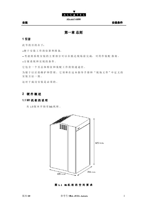
2 硬件概述1.1 M1机柜的说明从 1.3版本开始有 M1机柜。
图 1.1 M1机柜的空间要求安装 安装条件M1机 柜 用 于 小 容 量 。
MPS : 市 电图 1.2 M1机 柜 的 配 置根 据 配 置 , 功 耗 举 例 表带 机 格 的M1机 柜 平 均 重 量 为 40公 斤 。
1.22.2 WM1机 柜 (壁挂式 )和 VH(语 音 集 线 器 )注 :WM1 的 安 装 详 见 “ 操 作 手 册 ” 的 第 23部 分 。
VH 的 安 装 详 见 “ 操 作 手 册 ” 的 第 28部 分 。
安装安装条件1.32.3 PWSC机柜的说明PWSC(电源机柜 )机柜适用于中等容量 (M2机柜 )。
从 1.3 版本开始有 PWSC机柜。
图 1.3 PWSC机柜的空间要求PWSC机柜和它的机格的平均重量为 35公斤。
图 1.4 PWSC机柜的配置安装安装条件2.4 M2机柜的说明图 1.5 M2机柜的空间要求安装 安装条件M2机 柜 适 用 于 中 等 容 量 , 它 的 不 同 配 置 有 :图 1.6 M2机 柜 的 不 同 配 置不 同 配 置 的 功 耗 举 例 表 :带 机 格 的 M2机 柜 平 均 重 量 为 70公 斤 。
安装安装条件2.5 M3机柜的说明图 1.7 M3机柜的空间要求安装 安装条件M3机 柜 适 用 于 大 容 量 , 它 的 不 同 配 置 有 :图 1.8 M3机 柜 的 不 同 配 置不 同 配 置 的 功耗 举 例 表 :带 机 格 的 M3机 柜 平 均 重 量 为 110公 斤 。
思科4400系列WLC快速使用指南
思科4400系列WLC快速使用指南目录关于本手册 (3)安全声明 (3)控制器介绍 (3)控制器状态灯 (4)WLC开箱与操作 (5)WLC组件 (5)需要的工具和信息 (5)初始化系统配置信息 (6)选择位置 (6)连接到WLC的Console口 (7)运行启动脚本和系统自检 (8)使用启动向导 (11)登录WLC (12)核实接口配置和状态 (13)连接网络(汇聚) (14)Model 4402 Controllers (14)Model 4404 Controllers (14)连接WLC服务端口(可选) (14)链接AP (14)安装电源模块 (14)准备工具 (15)安装VPN模块 (16)准备工具 (16)关于本手册本手册用来帮助您了解CIsoc4400系列WLC的安装和最小化配置。
主要包括以下WLC 型号: 4402-25, 4402-50, 4404-25, 4404-50, and 4404-100.安全声明使用前注意一下事项:•确保环境温度在32 to 104° F (0 to 40° C)•确保充足的供电.•确保电源接地.控制器介绍Cisco 4400系列控制器(WLC)为无线网络部署提供最高级别的性能和扩展性,并且保护网络中现有的投资。
作为无线网络的核心部分,控制器可以提供安全、干扰检测、射频管理、服务质量保障、无线漫游等功能,并可以和其他控制器、Cisco无线控制系统(WCS)、AP协同工作,以提供一个完善的无线网络方案。
为了更好地使用本文,我们假定您已经完成了无线网络的结构设计。
射频资源管理功能自动检测并配置网络中出现的AP。
4400系列WlCT包括两款型号4402和 4404。
4402有两个分布式千兆以太网接口,每个接口可以管理多达48个AP,尽管如此,Cisco建议为了保证带宽每个接口管理的AP数量不要超过25个。
4402-25和4402-50分别支持25和50个AP注册到WLC中。
AlcatelOXE(阿尔卡特)4400交换机用户操作培训资料
AlcatelOXE(阿尔卡特)4400交换机用户操作培训资料ALCATELA4400用户操作及培训资料目录目录1. 4400交换机机架简介 (3)2. 4400交换机功能板简介 (4)3. 4400交换机系统命令 (6)4. 开关机方法及注意事项 (7)5. 4400交换机系统数据管理 (8)6. mgr 管理工具 (9)7. 分机管理 (10)8. 组管理 (13)9. 中继管理 (15)10. 号码编译 (20)11. 类别管理 (23)12. 用户数据备份 (31)1.4400交换机机架简介左图为4400机架ACT 是用于插交换机功能板的分架。
ACT编号从0开始(如:ACT0、ACT1)。
4400有两种ACT,ACT14和ACT28。
ACT14有14个槽口,可插14块功能板(如左图的ACT1);ACT28有28个槽口,可插28块功能板(左图中的ACT2)。
系统有固定的设备号(即物理地址),设备号由ACT号、槽口号和功能板上的电路号组成(如:ACT0上的第5槽口的UA32板上的第一个端口的设备号为0-5-0,ACT1上的第11槽口的UA32板上的最后一个设备号为1-11-31)2.4400交换机功能板简介CPU-3、CPU-5? 主控板(板上有CPU、硬盘、内存条等主控设备)Z12、Z24? 模拟用户板(板上有12个或24个模拟用户端口,通过交换机后板电缆经配线架接普通电话机)UA16、UA32? 数字用户板(板上有16个或32个数字用户端口, 通过交换机后板电缆接ALCATEL的数字设备,如:4004话机、4010话机、4020话机、4035话机、4048话务台及其他数字设备)NDDI? 模拟中继板(板上有8个模拟中继端口, 通过交换机后板电缆接电信中继)PRA2? T2数字中继板式(板上有30个T2数字中继通道, 通过交换机后板电缆或同轴电缆接电信中继) VG? 语音板(板上可插闪存卡,提供系统的语音提示及保留音乐)SUVG? SU语音板(板上可插闪存卡,提供系统的语音提示及保留音乐,并提供双音频接收功能) MMSFD? 软驱板(板上有1.44M软驱,通过软驱可对系统进行数据备份)INTOF? ACT分架接口板(各ACT分架通过此板与主ACT-CPU 分架进行联接)GPA? 功能辅助板(提供29方会议功能,并可插闪存卡,提供系统的语音提示及保留音乐或双音频接收)VPS35? 语音信箱板(提供系统内置语音信箱服务功能) DECT4? 内部移动电话板(提供内部移动电话功能)BRA2? T0/S0接口板(板上有8个T0/S0端口,通过后板电缆接2B+D中继和用户)PCM2? PCM数字中继板(板上有30个PCM数字中继通道, 通过同轴电缆接电信的中国一号中继)EMTL? Tie-Line中继板(提供Tie-Line组网功能)LIOE? IP接口板(提供系统IP电话接口及其它IP接口)LIOB? DDN接口板(提供 64K/128K DDN中继接口)IO2? 输入输出板(提供系统额外的辅助接口)RT2? 远端ACT分架接口板(远端ACT分架通过此板与主ACT分架进行联接)3. 4400交换机系统命令登录系统命令和密码退出系统命令a4400a> exit系统复位命令注:系统所有的命令必须都是小写的英文字母4.开关机方法及注意事项关机步骤在a4400a>下输入shutdown –ih,回车后等屏幕显示完毕后把CPU上电源开关关闭(开关把手指向OFF处)。
Alcoswitch MSS420004 四极双极开关说明书
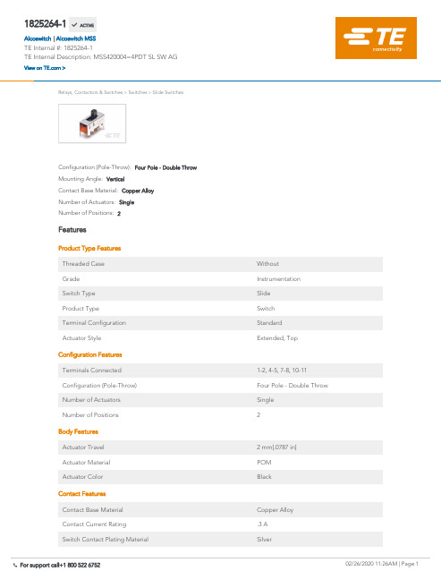
1825264-1MSS420004=4PDT SL SW AG02/26/2020 11:26AM | Page 1 For support call+1 800 522 6752Relays, Contactors & Switches>Switches>Slide SwitchesNumber of Positions:2Number of Actuators:SingleContact Base Material:Copper AlloyMounting Angle:VerticalConfiguration (Pole-Throw):Four Pole - Double ThrowFeaturesProduct Type FeaturesThreaded Case WithoutGrade InstrumentationSwitch Type SlideProduct Type SwitchTerminal Configuration StandardActuator Style Extended, TopConfiguration FeaturesTerminals Connected1-2, 4-5, 7-8, 10-11Configuration (Pole-Throw)Four Pole - Double ThrowNumber of Actuators SingleNumber of Positions2Body FeaturesActuator Travel 2 mm[.0787 in]Actuator Material POMActuator Color BlackContact FeaturesContact Base Material Copper AlloyContact Current Rating.3 ASwitch Contact Plating Material SilverTermination Features1825264-1 ACTIVEAlcoswitchTE Internal #:1825264-1TE Internal Description:MSS420004=4PDT SL SW AGView on >Alcoswitch MSS|Termination FeaturesTermination Type PCMechanical AttachmentPCB Mount Retention WithPCB Mount Retention Type Guide PostMounting Angle VerticalMounting Type Through HoleDimensionsPCB Tail Length 2.8 mm[.11 in]Actuator Length8 mm[.315 in]Width9.4 mm[.3701 in]Length15 mm[.5906 in]Identification MarkingStamped Marking WithIndustry StandardsUL Flammability Rating UL 94-HBPackaging FeaturesPackaging Method TrayProduct ComplianceFor compliance documentation, visit the product page on >EU RoHS Directive 2011/65/EU CompliantEU ELV Directive 2000/53/EC CompliantChina RoHS 2 Directive MIIT Order No 32, 2016No Restricted Materials Above ThresholdEU REACH Regulation (EC) No. 1907/2006Current ECHA Candidate List: JUL 2019(201)Candidate List Declared Against: JUL 2017(174)Does not contain REACH SVHCEU REACH Regulation (EC) No. 1907/2006Current ECHA Candidate List: JUL 2019(201)Candidate List Declared Against: JUL 2017(174)Halogen Content BFR/CFR/PVC Free, but Br/Cl >900 ppm inother sources.Solder Process Capability Wave solder capable to 265°C02/26/2020 11:26AM | Page 2 For support call+1 800 522 675202/26/2020 11:26AM | Page 3For support call+1 800 522 6752Solder Process CapabilityWave solder capable to 265°CProduct Compliance DisclaimerThis information is provided based on reasonable inquiry of our suppliers and represents our current actual knowledge based on the information they provided. This information is subject to change. The part numbers that TE has identified as EU RoHS compliant have a maximum concentration of 0.1% by weight in homogenous materials for lead, hexavalent chromium, mercury, PBB, PBDE, DBP, BBP, DEHP, DIBP, and 0.01% for cadmium, or qualify for an exemption to these limits as defined in the Annexes of Directive 2011/65/EU (RoHS2). Finished electrical and electronic equipment products will be CE marked as required by Directive 2011/65/EU. Components may not be CE marked.Additionally, the part numbers that TE has identified as EU ELV compliant have a maximum concentration of 0.1% by weight in homogenous materials for lead, hexavalent chromium, and mercury, and 0.01% for cadmium, or qualify for an exemption to these limits as defined in the Annexes of Directive 2000/53/EC (ELV). Regarding the REACH Regulations, TE’s information on SVHC in articles for this part number is still based on the European Chemical Agency (ECHA) ‘Guidance on requirements forsubstances in articles’(Version: 2, April 2011), applying the 0.1% weight on weight concentration threshold at the finished product level. TE is aware of the European Court of Justice ruling of September 10th, 2015 also known as O5A (Once An Article Always An Article) stating that, in case of ‘complex object’, the threshold for a SVHC must be applied to both the product as a whole and simultaneously to each of the articles forming part of its composition. TE has evaluated this ruling based on the new ECHA “Guidance on requirements for substances in articles” (June 2017, version 4.0) and will be updating its statements accordingly.Slide Switches(20)TE Model / Part #1825257-1MSS120004=SPDT SL SW VERT AGTE Model / Part #1825255-8MHS133G04=SP3T SL SW VERT AUTE Model / Part #1825255-7MHS13304=SP3T SL SW VERT AGTE Model / Part #1825255-5MHS12304=SPDT SL SW VERT AGTE Model / Part #1825258-2SPDT SL SW R/A AUCompatible PartsAlso in the Series Alcoswitch MSSCustomers Also BoughtTE Model / Part #3-1825010-7 ASE6204=6PDT AUTOSLIDETE Model / Part #2041517-1MINI USB, RCPT,V/T,DIP, B TYPE,30u"AuTE Model / Part #1825267-1MSS430004=4P3T SL SW AGTE Model / Part #1825257-1MSS120004=SPDT SL SW VERT AGTE Model / Part #6-2176070-0 3521 3K0 1% 2WTE Model / Part #282856-2TERMI-BLOK PCB MOUNT 2PTE Model / Part #5-146256-306 MODII HDR DRST B/A .100CL LTE Model / Part #5-146285-202 MODII HDR SRST B/A .100CLTE Model / Part #5-146285-303 MODII HDR SRST B/A .100CLCustomers Also BoughtDocumentsProduct DrawingsMSS420004=4PDT SL SW AGEnglishCAD FilesCustomer View ModelENG_CVM_CVM_1825264-1_A.2d_dxf.zipEnglish3D PDF3DCustomer View ModelENG_CVM_CVM_1825264-1_A.3d_igs.zipEnglishCustomer View ModelENG_CVM_CVM_1825264-1_A.3d_stp.zipEnglishBy downloading the CAD file I accept and agree to the of use.Terms and ConditionsDatasheets & Catalog Pages02/26/2020 11:26AM | Page 4 For support call+1 800 522 6752Datasheets & Catalog PagesSWITCHES_CORE_PROGRAM_CATALOGEnglishProduct Environmental ComplianceTE Material DeclarationEnglish02/26/2020 11:26AM | Page 5 For support call+1 800 522 6752。
恒洁4400系列水槽锁定辅助设备说明书
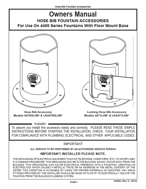
97886C (Rev. D - 09/15)PAGE 1Owners ManualHOSE BIB FOUNTAIN ACCESSORIESFor Use On 4400 Series Fountains With Floor Mount BaseInstallerTo assure you install this accessory easily and correctly, PLEASE READ THESE SIMPLE INSTRUCTIONS BEFORE STARTING THE INSTALLATION. CHECK YOUR INSTALLATION FOR COMPLIANCE WITH PLUMBING, ELECTRICAL AND OTHER APPLICABLE CODES.Hose Bib AccessoryModels 4470NLHB* & LK4470NLHB*Locking Hose Bib Accessory Models 4471LHB* & LK4471LHB*IMPORTANTALL SERVICE TO BE PERFORMED BY AN AUTHORIZED SERVICE PERSONIMPORTANT! INSTALLER PLEASE NOTE.THE GROUNDING OF ELECTRICAL EQUIPMENT SUCH AS TELEPHONE, COMPUTERS, ETC. TO WATER LINES IS A COMMON PROCEDURE. THIS GROUNDING MAY BE IN THE BUILDING OR MAY OCCUR AWAY FROM THE BUILDING. THIS GROUNDING CAN CAUSE ELECTRICAL FEEDBACK INTO A FOUNTAIN, CREATING AN ELECTROLYSIS WHICH CAUSES A METALLIC TASTE OR AN INCREASE IN THE METAL CONTENT OF THE WATER. THIS CONDITION IS AVOIDABLE BY USING THE PROPER MATERIALS AS INDICATED. ANY DRAIN FITTINGS PROVIDED BY THE INSTALLER SHOULD BE MADE OF PLASTIC TO ELECTRICALLY ISOLATE THE FOUNTAIN FROM THE BUILDING PLUMBING SYSTEM.PAGE 297886C (Rev. D - 12/15)DESCRIPTION75624C 75619C 45836C*70977C 70972C 75623C 66555C 66475C 66641C 75535C 45837C*45838C*75521C123456789101112NSPART NO. Fitting - Hose Vacuum Breaker Faucet - 1/2" NPTPanel - Access W/Bib Recess Nut - Lock 1/2" Conduit Elbow - 90° x 1/2" MPTFitting - Tee 1/2" X 1/2" X 3/8"Tube - 1/2" O.D. X 35.00" Lg.Tube - 3/8" O.D.Tee to Strainer Tube - 1/2" O.D. X 4.38" Lg.Screw - 1/4-20 X 3/4" Torx Panel - Locking Hose Bib Door - Locking Hose Bib Bit - Pinned Torx T-27ITEM NO.PARTS LISTFOUNTAIN BODY (EXISTING)123FINISHED GRADEINSTALLATION INSTRUCTIONS1. Shut off water supply to fountain.2. Determine location for installation of Hose Bib Accessory . Remove existing access cover plate. This accessory is designed to replace the existing access cover.3. Disconnect the fountain water line from the main water supply. Connect Tube (Item 8) to existing fountain strainer as shown below.4. Connect T ee (Item 6) to Tube (Item 8). Connect main water supply to Tee using 1/2" Copper Tube (Item 9). DO NOT TURN MAIN WATER SUPPLY ON AT THIS TIME !5. Connect Hose Bib Accessory water line to the Tee and to the Elbow (Item 5) on the Access Panel (Item 3) using 1/2" Copper Tube (Item 7) as shown below, maintain loop in coil to facilitate installation and removal of Access Panel.6. Turn on main water supply. Check for leaks. If there are leaks, turn off main water supply and correct the water leaks as required. After insuring that all connections are leak free, leave main water supply on and replace any panels that may have been removed in the installation process.7. Assemble Hose Bib Accessory to the main fountain body.456789WATER INLETSTRAINERTO FOUNTAIN REGULATOR (EXISTING)111012LOCKING HOSE BIBFOUNTAIN BODY (EXISTING)PRINTED IN U.S.A.Halsey Taylor – Elkay – FOR PARTS CONTACT YOUR LOCAL DISTRIBUTOR OR CALL TECHNICAL SERVICES AT 1.800.834.48162222 CAMDEN COURT, OAK BROOK, ILLINOIS 60523*FINISH COLOR OPTIONS – Choose color option to complete your model number, add as suffix example: 4470NLHB EVGMatte finish: Evergreen = EVG Gloss finish: Beige = BGE Gray = GRYTerracotta = TER Black = BLK Orange = ORN White = WHT Blue = BLU Purple = PUR Yellow = YLWBrown = BRNRed = RED*select color option to complete part number NS = Not Shown。
凯美达四位炉热量为440000BTU的产品说明书
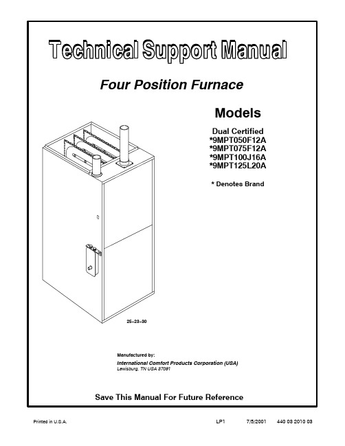
LP17/5/200144003201003Printed in U.S.A.*9M P T075F12A1Brand Identifier Engineering Rev. T=Tempstar Denotes minor changes C=Comfortmaker/Keeprite Marketing Digit H=Heil/Arcoaire Denotes minor change N=Non--Brand Specific(Generic)Cooling Airflow Efficiency Identifier08=800CFM 8=Non--Condensing,80+%Gas Furnace12=1200CFM 9=Condensing,90+%Gas Furnace14=1400CFM Installation Configuration16=1600CFM UP=Upflow DN=Downflow UH=Upflow/Horizontal20=2000CFM HZ=Horizontal DH=Downflow/HorizontalMP=Multiposition,Up/Down/Horizontal Cabinet Width Major Design Feature B=15.5²Wide 1=One(Single)Pipe N=Single Stage F=19.1²Wide 2=Two Pipe P=PVC Vent J=22.8²Wide D=1or2Pipe T=Two Stage L=24.5²Wide L=Low NOx V=Variable Speed Input(Nominal MBTUH) *Denotes brand(T,H or C)Manufacturers Number(Mfr No--See Rating Plate)ALL ModelsSpecificationsGeneralGas Type Nat LPTransformer Size(VA) T’stat Heat Anticipator 40 .10Gas&IgnitionGas ValveRegulation TypeManifold Press.Hi Fire(²WC)Lo Fire(²WC)HW SV9541SNAP3.51.7HW SV9541SNAP10.04.9Pilot Orifice Size.018.011 Ignition Type/Series HW HSPFan ControlsFan Control(Type)Fan Control On (Timed--secs)OffHW ST9162A30/60 60,100,140,180Gas Conversion Kits All Models Nat to LP NAHF002LP*1011789 LP to Nat NAHF002NG*1011787 *Order from Service PartsSpecifications*9MPT050F12A*9MPT075F12A*9MPT100J16A*9MPT125L20AGeneralInput(Btuh)Std/Alt.Hi FireLo Fire Output(Btuh)Std/Alt.Hi FireLo Fire Temp.Rise(°F)Hi FireLo Fire 50,00035,00046,00032,20035--6525--5575,00053,00069,00048,80040--7030--60100,00070,00092,00064,40040--7030--60125,00087,500115,00080,50040--7030--60Electrical(Volts/Hz/FLA)115/60/9.8115/60/8.9115/60/9.0115/60/11.2Gas&IgnitionGas TypeStd.Main Orifices(No/Size)Nat.2/42L.P.2/54Nat.3/42L.P.3/54Nat.4/42L.P.4/54Nat.5/42L.P.5/54CombustionFlue Outlet Size(Inches) Std.Outlet Temp(°F)2<1402<1403<1403<140@Blower/@Transition Box(Hi Fire)Std.Pressures(²of WC)5¢No Elbows40¢+5--90°DWV Elbows@Blower/@Transition Box(Lo Fire) Std.Pressures(²of WC)5¢No Elbows40¢+5--90°DWV Elbows --1.80/--2.60--1.30/--2.30--1.20/--1.90--1.00/--1.80--1.80/--2.60--1.30/--2.30--1.20/--1.90--1.00/--1.80--1.80/--2.60--1.70/--2.50--1.20/--1.90--1.00/--1.80--1.80/--2.60--1.70/--2.50--1.30/--2.30--1.20/--2.20Limits&Controls Rollout Switch(°F) Limit Control Setting(°F)300260300240300240300180Std.Pressure Sw.(Part No)Blower Switch Pressure(Close)Blower Switch Pressure(Open)Transition Switch Pressure(Close) Transition Switch Pressure(Open)10135150.950.801.701.5010135150.950.801.701.5010135150.950.801.701.5010131661.301.101.801.60High Altitude Pressure Sw.(Part No) Blower Switch Pressure(Close)Blower Switch Pressure(Open)Transition Switch Pressure(Close) Transition Switch Pressure(Open)10131650.700.551.401.2010131650.700.551.401.2010131650.700.551.401.2010131570.850.701.701.50Blower DataType&SizeMotor Amps/RpmMotor Type/H.p.Cap.Mfd/VoltsFilter TypeCool Cap.(Tons)@.5²W.C.L,ML,MHi&Hi11--810/850PSC/1/27.5/37016x25x111/2,2,21/2,311--108.0/1050PSC/1/27.5/37016x25x111/2,2,21/2,311--1010/1050PSC/1/210/37016x25x121/2,3,31/2,411--1013/900PSC/3/440/37016x25x1(2)31/2,4,41/2,5CIRCULATION AIR BLOWER DATAFor050Models3Ton UnitsSpeedTap Low Med L Med H Hi0.18261083130114080.28041050124213470.37701028119512950.4735985115312370.5698952109311830.6657909104011180.7------86393510530.8--------8128659760.9------------8028871.0------------720787For075Models3Ton UnitsSpeedTap Low Med L Med H Hi0.1706917116313680.2677875112013190.3636840107612630.459581*********0.554676698711480.649070288910770.7------6308219890.8------5507509140.9------4626768331.0------------601747For100Models4Ton Units For125Models5Ton UnitsSpeedTap Low Med L Med H Hi 0.1823110915271850 0.2795108714821791 0.3747105614261720 0.4677101613821648 0.561797013171575 0.654485412451485 0.7------76311541401 0.8------652104312840.9------------90511611.0------------7371028SpeedTap Low Med L Med H Hi 0.11720191021272315 0.21686188120872268 0.31644183320242201 0.41600177719612131 0.51533172018912029 0.61494164718041948 0.71413157117081820 0.813061470160417300.9--------1349148416141.0----------------132814305440032010031.Wiring DiagramN2 S T A G E851624137NS E N S O R(S O M E M O D E L S )C A P A C I T O R I G N I T E RH U ME A CNM O T O RI N D U C E RI N D H L O NH I G H21H O TN E U T R A LO N L YC O ND U C T O R S C O P PE R G N DRB K WB LB KYI G N I T E RS E N S O RRG A S V A L V E HEAT OFF DELAY HEAT O N DELAY THER MOSTAT TYPE3M A I N L I M I T43SETTINGFACTORY 60 SEC.100 SEC.SINGLE STAGE12121212312 2 STAGE30 SEC.FAN CONTROL M ODULE4434312YB LRRG T H E R M O S T A TS I N G L E S T A G E R B LYWY4 5 61 3 2B LWGB R T R A N S F O R M E RB RC B K T R A N S F O R M E R115VX F M R24V24V A CC O M 28196P 13543O NC O N N E C T I O ND I A G R A MD I S C O N NE C T B EF O R E S E R V I C I N GD A N GE R : E L E C T R I C A L S H O C K H A Z A R D4S W I T C H I N T E R L O C K COOL OFF DELAY: 60 SECCOOL ON DELAY: 5 SE C EA C + HUM: 0.8 A MAX. C OMBINEDB O XC O N N E C T I O N F I E LD 10133601S1V A L V E G A S AC I R C U I T B O A R DG N D .C O O L H I (B K )H E A T H M H I (O )H E A T L M L O (B L )M 1 L O (R )C O N T (O P T )L 1L 1L 1L 1L 1M 2S W I T C HP R E S S U R E L O W F U R N A C E C O N T R O LD E P E N D I N G O N M O D E L1 T O 3 I N S E R I E S R O L L O U T S W I T C H M A I N L I M I TS W I T C HH I G H P R E S S U R E R C Y W 1GW 2R G W 2W 1R G 1 2 3 4A(H I V O L T F I E L D ) GW 1 Y W 2 R T H E R M O S T A T 2-S T A G E 60H Z 115V 6155A F U S EM 2M 1F U S E5 A S E E M A N U A L S F O R A D J U S T I N G S P E E D T A P S F O R P R O P E R H E A T I N G , C O O L I N G & C I R C U L A T I N G S P E E D S .2I N T E R N A L C I R C U I T B O A R D W I R I N GL O W V O L T A G E F I E L D L O W V O L T A G E F A C T O R Y L I N E V O L T A G E F I E L D L I N E V O L T A G E F A C T O R Y *O R A N G E -M H I R E D -L OB L AC K -H I B L U E -M L O S P E ED T A P C O D EHEAT LOWIND LOW P U R P L E PY E L L O W Y W H I T E W R E D R O R A N G E O G R E E N G B R O W N B R B L U E B L B L A C K B K IND IN IND HI 3C O L O R C O D E24V S E C O N D A R Y115V P R I M A R YP 1443217844343124360 SEC.180 SEC.140 SEC.E A C-B L S W I TC HP R E S S U R E H I G H S E R I E S D E P E N D I N G O N M O D E LR O L L O U T S W I T C H 1 T O 3 I N OB LB LO M O T O RI N D U C E R WB R B RR B K O RN E U T R A L(S O M E M O D E L S )C A P A C I T O R H E A T H IC O O LH U MC O N TB K B K RR W WWS W I T C HP R E S S U R E L O W W W+2 S T A G EB K P B KB L(L P M O D E L S O N L Y )S W I T C HL P P R E S S U R E W 34RO N2 S T A G E234-+T H E R M O S T A TY-+43V A L V EG A S 21W 2YGYP 1XFMR DC MTRV A C24 LINE 120 VAC C O M3241 M O T O RB L O W E R P SC 4(L P M O D E L S O N L Y )S W I T C H L P P R E S S U R E 1212WP 2Y 2C GY W 1C A P A C I T O RR 7W 1W 2M O T O RB L O W E R P SC NNA W M - 105°C W I R E O R I T S E Q U I V A L E N T .M U S T B E R E P L A C E D , I T M U S T B E R E P L A C E D W I T H T Y P E I F A N Y O F T H E O R I G I N A L W I R E A S S U P P L I E D W I T H T H E A P P L I A N C E P 21234756H O T 115V -60H Z N E U T R A LS W I T C H I N T E R L O C K L A D D E R D I A G R A ML 1L 1I N D I NH U ML 1E A CI N D LL 1C A P A C I T O R89542R6315467138223412.(*9MPT)44003201003Key Description Part *9MPTNo.FunctionalNumber 050F12075F12100J16125L201Heat Exchanger,Primary10128501012854101285810128621--------1--------1--------12Heat Exchanger,Secondary10125651012569101257310125771--------1--------1--------13Motor,Blower1009052101334110119061--------1--1--------14Mount,Motor kit 10133795220200241----1--1--15Wheel,Blower 101301110114201----1--1--16Transformer101272211117Capacitor,10Mfd.,370V7.5Mfd.,370V 40Mfd.,370V 1094956109423910121761------1--1--------18Control,Fan Timer 101208411119Switch,Interlock 1012351111110Switch,Pressure 10131661013515--1--1--11--11Blower,Exhaust101335710133761--1--1----112Valve,Gas HSP Nat.2Stage 1013351111113Burner,Pilot HSP 1008731111114Igniter/Sensor HSP 1009524111115Orifice,Burner #42Nat.1011351234516Switch,Limit (Rollout)1013102333310087231------17Burner Assembly------1008724--1------10087251008726------1--118Switch,Limit (Main)13203663433500210084451------1----1------119Orifice,Pilot.018503211111120Filter,HH 16X25X 1/2”10103651122Key Description Part *9MPTNo.Non-FunctionalNumber 050F12075F12100J16125L20A Panel,Top 1012342101234310123441----1------1------1B Gasket,Top Panel 1012603101260410126051----1------1------1FPartition,Blower10131641012877101316210131631--------1--------1--------1H Housing,Blower 101297210128881----1--1--1J Panel,Blower Cutoff7210200137210200081----1--1--1K Hanger,Blower10123282222LDoor,Blower (Comfortmaker only)(Comfortmaker only)(Comfortmaker only)(Heil only)(Heil only)(Heil only)(Tempstar only)(Tempstar only)(Tempstar only)1013141101314210131431013138101313910131401013394101339510133961----1----1----1----1----1------1----1----1------1----1----1M Bracket,Door Filler10135161012896101289710128981--------1--------1--------1NDoor,Front (Comfortmaker only)(Comfortmaker only)(Comfortmaker only)(Heil only)(Heil only)(Heil only)(Tempstar only)(Tempstar only)(Tempstar only)1013148101314910131501013145101314610131471013397101339810133991----1----1----1----1----1------1----1----1------1----1----1O Clamp,Capacitor 109502010950221--1--1----1P Transition Assembly 1012281101228210122831----1------1------1Q Gasket,Blower 101258810134151--1--1----1R Board,Insulating 1012418101241910124201----1------1------1S Box,Collector 1012244101224510122461----1------1------1TGasket,Transition 10132631013080101308310130841--------1--------1--------1U Gasket,Collector Box 1012594101259510125961----1------1------1VPartition,Front Heat Exchanger10126501012648101265110126531--------1--------1--------1Key Description Part *9MPTNo.Functional Number050F12075F12100J16125L20W Gasket,Attachment Plate10125421012543101254410125452--------2--------2--------2X Cover,Junction Box10123501111 Y Box,Junction10123491111Z Tube,Pilot1012832101318910130771------1--1--------1AA Bracket,Pilot10109011111BB Manifold10129701012971101227810122791--------1--------1--------1CC Bottom,Burner Box1012334101233510123361----1------1------1DD Baffle,Burner Box1012338101233910123401----1------1------1EE Top,Burner Box1012330101233110123321----1------1------1FF Bracket,Manifold Support10123772222 GG Bracket,Burner Box Side10125322222 HH Bracket,Control Mounting10123211111 JJ Tube,Sensor10092381111 KK Trap,Drain Assembly10123221111LL Sightglass(Tempstar only)1013235101323611111111MM Wrapper,Filter Rack7410100391122 NN Front,Filter Rack7410200011122 OO Cover,Filter27910431122 PP Clip,Filter10084823333 QQ Baffle,Air Coil10122472222 )(PART NOT ILLUSTRATED)(Elbow Vent Asy.90+10134951111 )(Coupling,Air Intake10122841111 )(Gasket,Air Intake10125831111 )(Gasket,Trap10126101111 )(Elbow,Vent90+10126171111 )(Hose,Drain1/2”10126951111 )(Hose,Drain5/8”10126961111)(Tube,Drain Rigid1013356101342710134281----1------1------1)(Clamp,Hose5/8”10129752222 )(Clamp,Hose3/4”10129764444 )(Grommet,Vent10126971111 )(Clamp,Hose10027931111Key Description Part*9MPTNo.Functional Number050F12075F12100J16125L20 )(Bushing,Strain Relief19452871111 )(Grommet,Vinyl10095351111 )(Plug,Rubber10575731111 )(Harness,Wire101335810133591--1----1--1 )(Manual,Technical/Parts List440032010031111 )(Manual,Users440022010011111 )(Manual,Installation440012010021111 Gas Conversion Kits--All modelsNat to LP*1011789LP to Nat*1011787*Must be ordered from Service Parts。
Kestrel 4400 Heat Stress Tracker 使用说明书

23Guidelines...............................................................................4Wet.Bulb.Globe.Temperature..............................................4Thermal.Work.Limit...............................................................6Vane.Mount.Assembly...........................................................9Data.Logging........................................................................10Glossary.................................................................................10Maintenances.&.Services....................................................12Warranty.. (13)NK, manufacturer of Kestrel Pocket Weather Trackers, is available to answer questions and provide support. Contact NK by phone: 610.447.1555; fax: 610.447.1577; email:***************;www.GlobalTestSupply .comQuality Kestrel Products Online at:**************************45The unit will calculate and display Wet Bulb Globe Temperature based on Globe Temperature, Relative Humidity, Ambient Temperature, Barometric Pressure, and Wind Speed.• Press while on the Wet Bulb Globe Temperature • • Use to scroll to “App”change the Application.• Press to exit the WBGT settings screen....Note:..Flags.for.WBGT.are.listed.in.figure.1.(page.6)..If.red.or.black.flags.are.displayed,er.with.the.screen.contrast.inverting..Unless.the.screen.says.“No.flag”,rmation.on.work/rest.ratios.and.water.consumption.refer.to.Figure.1.The Kestrel 4400 Heat Stress Tracker will only yield accurate measurements using the following guidelines. It is important that the 4400 be fully acclimated to the measurement environment for accurate readings..Proper Placement id.on.the.ground,er’s.conditions..To.ensure.proper.placement,pact.Collapsible.Tripod.and.the.vane.mount.(included).Optimal Acclimating Time ...If.taken.from.a.cool.climate,.where.the.Kestrel.4400.Heat.Stress.Tracker.was.stored,.to.an.outside.heat.stress.climate,.the.unit.will.need.to.adjust.accordingly..Give.the.unit.a.minimum.of.7.minutes.to.adjust.to.the.outside.climate.if.taken.from.storage.(examples:.air.conditioned.building,.car.glove.box,.truck.gearbox,.etc)..10.minutes.of.acclimatization.time.is.recommended..If.worn.on.the.person.without.the.Black.Globe.exposed,.the.Kestrel.4400.Heat.Stress.Tracker.will.need.at.least.2.minutes.to.display.accurate.measurements.(examples:.jeans.pocket,.shirt.pocket,.etc).Repeat Measurements ...When.transporting.the.4400.with.the.intention.of.taking.repeat.measurements,.such.as.on.a.hike.or.march,.try.to.keep.the.unit.exposed.as.much.as.possible..A.Kestrel.Belt-Clip.Carry.Pouch.or.MOLLE-Compatible.Tactical.Carry.Pouch.is.ideal.for.this.purpose.as.the.Black.Globe.sensor.remains.exposed.to.the.air....Note:nd.traveled.when.mak-ing.judgments.on.heat.stress.and.personnel.capabilities..Figure.1:.Work/Rest.ratios.and.Water.Consumption.Guidelines..(Source:.U.S..Army.Center.for.Health.Promotion.and.Preventive.Medicine.Health..www.GlobalTestSupply .comQuality Kestrel Products Online at:**************************The unit will display Thermal Work Limit based on Globe Temperature, Relative Humidity, Ambient Temperature, Barometric Pressure, Wind Speed, and parameters specific to the population using the Thermal Work Limit measurement. These parameters are the Intrinsic Clothing Insulation Factor (IClo), Vapor Permeation Factor (VPF), Position of the body (Pos), and surface area of the person (Area). See Clothing...Note:..“Acclim”.will.blink.on.the.TWL.screen.when.the.meter.detects. that.Acclimatization.is.the.current.zone..In.the.Buffer.or.Withdrawal.zones,. rmation. on.TWL.interventions,.refer.to.Figure.2..For.typical.numeric.values.for.each. factor,.refer.to.Figure.3.• Press to exit the WBGT settings screen.• If Custom is selected, each factor specific to the usercan be altered (shown above).• To view the specifics of an ensemble, press afterselecting it.• If viewing the Custom ensemble specs, useto adjust each value, and orto scroll todifferent parameters.• Press to exit the ensemble specs, and once moreto exit TWL settings screen.Figure.2:..TWL.values,.working.zones,.and.interventions.Source:.Health.Authority,..Abu.Dhabi........................................................URL:.http://haad-safe.ae/index.php?option=com_content&view=article&id=27&Itemid=50.TWL (W.m )-2Working ZoneInterventions*Unacclimatized.workers.are.defined.as.new.workers.who.have.been.off.work.for.more.than.14.days.due.to.illness.or.leave........(outside.the.tropics).Quality Kestrel Products Online at:**************************7 6Figure.3:.(left/above).Typical.values.for.IClo,.VPF,.and. POS...Typical.value.for.Area.of.a.man.is.1.7...Sources:.“Heat.and.Moisture.Transfer.Through.Clothing”..(http:// /proceedings/BS2009/BS09_1360_1366. pdf),.and.“prehensive.Database.for.Estimating. Clothing.Insulation,”.Institute.for.Environmental. Research,.Kansas.State.University;.Elizabeth.McCullough. and.Byron.James.The Vane Mount was designed for extreme light weight andportability, and assembles in seconds. The Portable Vane Mountcontains four components: a zippered carry pouch, a cup bracket withincorporated level, a boom and a flight.Step 1Step 2Assemble the boom. Unfold thetwo pieces and stretch the bungeegently, then slide the two piecestogether (like a tent pole).Attach the flight to the flatend of the boom. Grasp the silverbungee end AND the transparentbungee washer, then pull the bungeeout about 1/2 an inch. Drop thebungee into the slot in the center ofthe flight while slipping the boomend into the opening in the centerof the flight.Step 4Step 5The assembled flight and boom looks like this.Attach the boom to the cup bracket.Locate the arrow on the inside of the cup bracket base.Insert the boom end in the direction of the arrow, allthe way through the base of the vane mount. Grasp thesilver bungee end AND the transparent bungee washer,then pull the boom back, stretching the bungee. Drop thebungee into the slot and slip the boom end into theopening near the compass. Gently rotate the boomuntil the angled end “seats” into the base of the opening.Attach the Vane Mount to yourtripod and level your tripod. Spinthe Vane Mount knob onto the 1/4-20mount on your tripod. Slip your Kestrelinto the Vane Mount with the displayfacing the bubble level and the back sideof the Kestrel facing the flight and boom.Adjust the flight so it is vertical. Observingthe level on the Vane Mount, carefully adjustyour tripod so the Vane Mount is level androtates freely and evenly.Quality Kestrel Products Online at:**************************981110Like WBGT, TWL uses environmental measurements, including thermal radiation, to predict work limits for people exposed to heat stress. Different attributes of clothing (such as its ability to insulate and allow water vapor to pass through it) are also used to calculate TWL.Acclimatization (Acclimatize)Defined as the process of gradually adjusting to a change in environment (such as a change in temperature, humidity, etc). During TWL mode “Acclim” will flash when the value being displayed falls within the acclimation zone. For example, people who have not worked in such condi-tions should not be left alone until they have acclimated, a process requiring at least several days.Black GlobeTypically a 6” copper sphere colored matte black with a thermometer in the center. This thermometer reads the surface temperature of the Black Globe, which indicates the radiant heat exposure of one in sunlight. The Kestrel 4400 Heat Stress Tracker uses a 1” Black Globe which is calibrated to achieve the same measurements as a 6” globe.Mean Radiant Temperature is primarily used to define the comfort of an individual in a defined, closed space (four walls and a ceiling). It is regarded as the most important measurement governing indoors comfort.The Kestrel 4400 Heat Stress Tracker’s Naturally Aspirated Wet Bulb Temperature function accounts for the effects of humidity on the human body. By combining relative humidity and wind speed, the temperature displayed is indicative of the evaporative cooling hap-pening to the Kestrel 4400.Wet Bulb Globe Temperature (WBGT)The WBGT is a composite measurement of Naturally Aspirated Wet Bulb, Globe Temperature & Dry Bulb Temperature. This environment data combines temperature, humidity, wind speed and thermal radiation to access heat stress.Outdoor WBGTIndoor WBGT= 0.7 T + 0.2 T + 0.1 T = 0.7 T + 0.3 T The Black Globe on the Kestrel 4400 Heat Stress Tracker is representa-tive of the amount of heat-absorption via the color black. Typically, Globe Temperature is taken using a 6” diameter copper globe painted black with an internal thermometer. However, the Kestrel 4400 Heat Stress Tracker uses a 1” copper globe painted black for its calculations. Globe Temperature is representative of the temperature of the Black Globe itself without accounting for air temperature.Black Globe temperature will fluctuate between, but always remain near, air temperature and Mean Radiant Temperature. This variability is due to wind speed. The faster the air moves over the globe ther-mometer, the closer Globe Temperature approaches air temperature. Inversely if there is zero movement of air, Globe Temperature equals Mean Radiant Temperature.Much like Globe Temperature, the Kestrel 4400 Heat Stress Tracker defines Mean Radiant Temperature as the effects of the environment on the Black Globe. However, Mean Radiant Temperature accounts for the dry air temperature and surface temperature of the Black Globe, whereas Globe Temperature is concentrated on temperature of the Black Globe itself....When.Autostore.is.on.and.the.unit.is.off,e.calculations.that.cannot.be.performed.without.power...When.reviewing.data.in.the.graphical.display,.the.symbol.“–“.will.appear.at.the.top.of.the.display.for.any.points.not.logged.due.to.the.above.condition.In wind-related measurements, a timer will appear at the bottom of the screen after starting the MMA feature – this timer displays the elapsed time. Additionally, for each minute this feature is running a data set will be stored in memory reflecting the instantaneous condi-tions at that time. This will happen regardless of memory settings.For additional information on memory options and logging data, please refer to the main Kestrel 4000 series manual.T = Naturally Aspirated Wet Bulb Temperature Where =T = Globe Temperature T = Dry Bulb Temperature www.GlobalTestSupply .comQuality Kestrel Products Online at:**************************BatteriesKestrel Pocket Weather Trackers require 2 AAA batteries. Average battery life is 300 hours based on typical use.For.the.Kestrel.4500,.it.is.important.to.re-insert.the.shim.along.with.the. pass.to.ensure.. correct.wind.direction.readings....W ing.the.Kestrel.meter.in.extremely.cold.weather,.it.is...................... e.lithium.batteries.for.optimal.performance. Maintenance & StorageTo avoid scratching the window, store the Kestrel Tracker in the soft pouch and/or use the Kestrel lens cleaning kit. SoftwareTo download the Kestrel Communicator software, visit: /kestrel-software.Calibrations, Certifications & ServiceEvery NK product is tested and calibrated before itleaves our factory. We warrant that it will perform within specifications when you receive it. The unit may be returned to NK for factory calibration, or you can contact NK for field calibration instructions (RH Calibration Kits are available on our website).Each Kestrel Meter comes with a Certificate of Conformity, stating the specifications for that product.If you are concerned your Kestrel is not performing within specifications upon receipt, please contact us and we will review your concerns. If necessary, we will test or recalibrate any unit within 30 days of purchase.Beyond 30 days, we offer reasonably-priced tests, calibration services, NIST-traceable calibrations, and full Kestrel Meter tune-ups.your return.Made in the USA1312NOTES: NOTES:Quality Kestrel Products Online at:**************************1514。
阿西亚(Asia)- VOLT-4400-技术手册说明书

Suchanetworkcouldvastlyspeedupand fluacrossRussia.”
to study the weather, but collected data only
6 ©2006NaturePublishingGroup
NATURE|Vol440|2 March2006
Nations’FoodandAgricultureOrganization regionanditspractices,heargues.“Ifyoudo thepowerfulacceleratorsbeingbuiltforphysi-
(FAO).“It’sjustabloodymess.”
nothavethat,thensurveillancewillstayinthe cists.Incomparison,epidemiologists“arestill
malmonitoringisoftenvirtuallynonexistent,withfewbasic
“H5N1hasputthe
againstthe“mirageoftechnol- Butmanyfeelthatalongsidesettinguplocal ogy”insurveillance.“Youdon’t centres,epidemiologyneedsafundamental
all,” says Peter Roeder, a field consultant withthe United
pimplesandwarts.”
buildinglargeteamsoflocal Headdsthatheisjealousofthemultimillionstaff,whoarefamiliarwiththe dollarsatellitesthatclimatescientistsenjoyand
- 1、下载文档前请自行甄别文档内容的完整性,平台不提供额外的编辑、内容补充、找答案等附加服务。
- 2、"仅部分预览"的文档,不可在线预览部分如存在完整性等问题,可反馈申请退款(可完整预览的文档不适用该条件!)。
- 3、如文档侵犯您的权益,请联系客服反馈,我们会尽快为您处理(人工客服工作时间:9:00-18:30)。
ALCATELA4400用户操作及培训资料目录目录1. 4400交换机机架简介 (3)2. 4400交换机功能板简介 (4)3. 4400交换机系统命令 (6)4. 开关机方法及注意事项 (7)5. 4400交换机系统数据管理 (8)6. mgr 管理工具 (9)7. 分机管理 (10)8. 组管理 (13)9. 中继管理 (15)10. 号码编译 (20)11. 类别管理 (23)12. 用户数据备份 (31)1.4400交换机机架简介左图为4400机架ACT 是用于插交换机功能板的分架。
ACT编号从0开始(如:ACT0、ACT1)。
4400有两种ACT,ACT14和ACT28。
ACT14有14个槽口,可插14块功能板(如左图的ACT1);ACT28有28个槽口,可插28块功能板(左图中的ACT2)。
系统有固定的设备号(即物理地址),设备号由ACT号、槽口号和功能板上的电路号组成(如:ACT0上的第5槽口的UA32板上的第一个端口的设备号为0-5-0,ACT1上的第11槽口的UA32板上的最后一个设备号为1-11-31)2.4400交换机功能板简介CUP-3、CUP-5→主控板(板上有CPU、硬盘、内存条等主控设备)Z12、Z24→模拟用户板(板上有12个或24个模拟用户端口,通过交换机后板电缆经配线架接普通电话机)UA16、UA32→数字用户板(板上有16个或32个数字用户端口, 通过交换机后板电缆接ALCATEL的数字设备,如:4004话机、4010话机、4020话机、4035话机、4048话务台及其他数字设备)NDDI→模拟中继板(板上有8个模拟中继端口, 通过交换机后板电缆接电信中继)PRA2→ T2数字中继板式(板上有30个T2数字中继通道, 通过交换机后板电缆或同轴电缆接电信中继)VG→语音板(板上可插闪存卡,提供系统的语音提示及保留音乐)SUVG→ SU语音板(板上可插闪存卡,提供系统的语音提示及保留音乐,并提供双音频接收功能)MMSFD→软驱板(板上有1.44M软驱,通过软驱可对系统进行数据备份)INTOF→ ACT分架接口板(各ACT分架通过此板与主ACT-CPU分架进行联接)GPA→功能辅助板(提供29方会议功能,并可插闪存卡,提供系统的语音提示及保留音乐或双音频接收)VPS35→语音信箱板(提供系统内置语音信箱服务功能)DECT4→内部移动电话板(提供内部移动电话功能)BRA2→ T0/S0接口板(板上有8个T0/S0端口,通过后板电缆接2B+D中继和用户)PCM2→ PCM数字中继板(板上有30个PCM数字中继通道, 通过同轴电缆接电信的中国一号中继)EMTL→ Tie-Line中继板(提供Tie-Line组网功能)LIOE→ IP接口板(提供系统IP电话接口及其它IP接口)LIOB→ DDN接口板(提供 64K/128K DDN中继接口)IO2→输入输出板(提供系统额外的辅助接口)RT2→远端ACT分架接口板(远端ACT分架通过此板与主ACT分架进行联接)3. 4400交换机系统命令登录系统命令和密码退出系统命令a4400a> exit系统复位命令a4400a> shutdown –◆慎用,系统将停机后重新启动。
在此期间所有电话服务将终止。
系统数据管理菜单命令系统安装管理菜单命令◆慎用,操作不当可能引发不可预测的故障。
仅对专业人员开放。
观察系统功能板状态命令观察话机状态命令a4400a> termstat d 分机号码如:观察中继线状态命令a4400a> trkstat –r 中继组号如:trkstat –观察系统CUP板工作状态命令a4400a> role –b切换系统CUP板工作状态命令◆在两块CPU之间进行切换系统功能板复位命令a4400a> rstcpl ACT号板位如:注:系统所有的命令必须都是小写的英文字母4.开关机方法及注意事项关机步骤在a4400a>下输入shutdown –ih,回车后等屏幕显示完毕后把CPU上电源开关关闭(开关把手指向OFF处)。
注意事项系统必须按照上述步骤关机, 若在系统SHUTDOWN之前强行关闭电源, 可能会导致系统出错。
开机步骤把CPU上电源开关打开(开关把手指向ON处)。
注意事项整个开机过程约需10分钟左右,在系统完全启动之前,切勿插拔任何电路板。
否则可能造成电路板的损坏。
5.4400交换机系统数据管理4400交换机(以下简称“系统”)提供以太网联接和串口联接两种方式。
以太网联接可用Telnet命令(如:Telnet 191.254.1.3 ‘191.254.1.3 ’为系统IP地址。
串口联接可用Terminal-终端仿真方式(串口速率9600、数据位8位、无校验、停止位1位,终端仿真VT100)。
登录系统login: mtcl ←输入登录帐号小写的“mtcl”Password: mtcl ←输入密码小写的“mtcl”# The role of the CPU is MAINApplication software identityR4.1-d1.305-4-g-cn-c5s2Business identification: R4.1Release:DELIVERY d1.305Patch identification: 4Dynamic patch identification: gCountry: cnCpu: c5s2ACD VERSIONrelease : 4bug_fixing : 4protocol_id : 62version_dy_hr_stat : 10v2.3灰色阴影部分为系统显示信息,可以忽略。
6. mgr 管理工具a4400a> mgr ←在系统管理菜中可用 “Enter ”键表示选中某项用“Ctrl+V ”键或“F1”键表示输入参数的确认后存盘 用“Ctrl+C ”或“F2”键表示不存盘退出。
Mgr 菜单注:以上有标识的为常用选项,其中灰色的部分(分机管理和组管理)为可由用户在现场培训后即可进行管理的项目。
其余项目则建议用户管理员在ALCATEL 工程师的指导下操作。
Shelf Atm Dect system Events Routing DiscriminatorSystem Security and Access Control Translator ← 号码编译管理 IP Categories ← 类别管理 Attendant Users ← 分机管理 Profiled Users Set Profiles Groups ← 组管理Abbreviated Numbering Phone Book Entities Trunk Groups ← 中继管理 External Services Inter-Nodes Links X25 DATAApplications Specific Telephone Services7. 分机管理在Shelf Atm Dect system Events Routing Discriminator System Security and Access Control Translator IP Categories Attendant Users ← 分机管理 Profiled Users Set Profiles Groups Abbreviated Numbering Phone Book Entities Trunk Groups External Services Inter-Nodes Links X25 DATA Applications Specific Telephone ServicesGo down hierarchyConsult/Modify ← 查阅或修改 Consult/Modify Overview of ObjectCreate ← 创建 Create Overview of Object Modify Modify Overview of ObjectDelete ← 删除 FORCED DELETE Memory re-initialization Facilities创建分机:上述参数中原有的值为系统默认值,一般情况回车忽略即可。
其中斜体字注释的参数根据系统配置情况设置分机类型ANALOG 是模拟话机4004、4010、4020和4035是常用的ALCATEL 数字话机 选中相应项目回车即可。
ANALOG 4035T 4620 (VPS + CLIP) 4004 & TSC DECT 4302 4010 & TSC DECT 4304 4021 (4020 & TSC DECT) 4321 4036 (4035 & TSC DECT) 4001 ANALOG with 4980 4011 4004 & TSC IP 4012 4010 & TSC IP 4023 4022 (4020 & TSC IP) 4034 4037 (4035 & TSC IP) 4040 GAP + S0 Set MULTIMEDIA PC 1 4610 (VPS No CLIP) MULTIMEDIA PC 2 4075 4074 GAP Handset 4003 4004 4010 40208.组管理◆系统有2种组,连选组和代接组。
连选组创建连选组注:1.Cyclical ←循环振铃2.Sequential ←依次振铃振铃方式3.Parallel ←同时振铃9.中继管理◆中继部分的参数应由ALCATEL工程师完成,不建议由用户自行修改。
在上页菜单中选择“Consult/Modify”项目可进入修改中继组修改中继组进一步修改中继组参数Node Number (reserved) : 1Trunk Group Id : 0Instance (reserved) : 1Trunk Group Type + NDDI (BCA)Public Network Ref. : outVG for non-existent No. + YESEntity Number : 0Supervised by Routing + NOVPN Cost Limit for Incom.Calls : 0 Immediat Trk Listening For VPNCall + YESVPN TS % : 50Csta Monitored + NOMax.% of trunks out CCD : 0Ratio analog.to ISDN tax : ------TS Distribution on Accesses + YESQuality profile for voice on IP + Profile #1IP compression type + DefaultUse of volume in system + YESDialling end to end + NOMax.% of trunks out CCD : 0Ratio analog.to ISDN tax : ------TS Distribution on Accesses + YESQuality profile for voice on IP + Profile #1IP compression type + DefaultUse of volume in system + YESDialling end to end + NODTMF end to end signal. + NOPaying Incoming Calls + NOTS Permanently assigned + YESMin. Nb.of digits on seize : 0Trunk group used in DISA + NO ←DISA功能DISA Secret Code : ---- ←DISA密码Routing To Executive + NODissuasion For ACD + NODTO joining + YESAutomated Attendant + NO ←自动话务员功能Calling party Rights category : 0Access Cluster Id : -1Collect Calls Allowed + YES注:上述参数建议使用原有的系统默认值。