Intel工业级主板M50说明书
Intel 系列主板 用户手册

版本: 0.1 2012年10月用户手册Intel 系列主板PCM-H161免责声明本手册内容系本公司知识产权,版权归本公司所有。
本产品的所有部分,包括配件与软件等其所有权都归本公司所有。
未经本公司书面许可,不得以任何形式对此手册和其中所包含的任何内容进行仿制、拷贝、摘抄或转译为其它语言文字。
我们本着对用户负责的态度精心地编写该手册,但不保证本手册的内容完全准确无误。
本手册为纯技术文档,无任何暗示及影射第三方之内容,且不承担排版错误导致的用户理解歧义。
若有任何因本手册或其所提到之产品的所有资讯,所引起直接或间接的信息流失或事业终止,本公司及其所属员工恕不为其担负任何责任。
由于我们的产品一直在持续的改良及更新,故本公司保留对本手册内容进行修正而不另行通知之权利。
版权声明本手册中所提及之商标,均属其合法注册公司所有。
本手册所涉及到的产品名称仅做识别之用,其所有权归其制造商或品牌所有人。
目 录第1章 综述 (4)1.1包装清单 (4)1.2主板规格 (5)1.3主板布局图 (6)1.4后置面板接口 (8)第2章 硬件安装 (9)2.1安装I/O后置面板 (9)2.2安装主板到机箱 (9)2.3 CPU安装 (9)2.4 内存安装 (10)2.5连接外部设备 (11)2.5.1 Serial ATA连接器 (11)2.5.2 MPCIE插槽 (11)第3章 跳线&接头安装与设置 (12)3.1跳线设置说明 (12)3.2清除CMOS设置跳线 (12)3.3 JDIMM跳线设置 (13)3.4JME跳线设置 (13)3.5 JBAT跳线设置 (13)3.6 前置面板插针接口 (13)3.7 JGPIO插针接口 (14)3.8 FUSB1/2插针接口 (14)3.9 前置音频输出接口 (15)3.10 COM连接口 (15)3.11 散热风扇接口 (16)3.12 电源接口 (16)第4章BIOS设置 (17)4.1 BIOS解释说明 (17)4.2 BIOS设定 (17)4.2.1进入BIOS设定程序 (17)4.2.2控制键位 (17)4.2.3 Main(BIOS主界面) (18)4.2.4 Advanced(高级BIOS功能设置) (18)4.2.5 Chipset(芯片组设置) (25)4.2.6 Boot (启动设置) (26)4.2.7 Secunity(安全设置) (27)4.2.8 Exit (离开BIOS设置程序) (28)第5章 安装驱动 (29)附录1 产品有毒有害物质或元素标示表 (30)PCM-H161ITX-IVXM5B12/ITX-IBXM6112 用户手册第1章 综述1.1 包装清单感谢您选用我们的产品。
TLIG31-77E2P-MGN 主板 说明书

主板用户手册
4.1 安装中央处理器(CPU)
TLIG31-77E2P-MGN 主板采用支持 INTEL 775 处理器的 Socket-775 插座,支 持 Intel LGA775(Prescott, Cedar Mill, Conroe),最新双核心处理器及 Intel Hyper-Threading(超线程技术)。为了保证 PC 可靠性,请确认你的处理器带散热片 和风扇。
序
号 元器件
用途
1 PS/2 鼠标连接端口
将 PS/2 鼠标插头连接到此端口
2 PS/2 键盘连接端口
将 PS/2 键盘插头连接到此端口
3 并口(可选)
您可以连接打印机/扫描仪及其他并口设备。
一个标准的 RJ-45 插孔以连接到本地局域网
4 LAN(可选)
(LAN) 。 10/100/1000M LAN 能 够 以 10 或
— 8 个 USB2.0 接口功能
符合 USB2.0 规范,最高速度为 480Mbit/sec
— 板载 LAN(可选)
板上自带10/100/1000M LAN接口 支持10Mb/s,100Mb/s和1000Mb/s自动交换模式 板载 LAN 标准
— 主板 I/O 接口功能
主芯片之间采用中心加速结构连接技术,提供了更高的数据交换带宽 1 个串行端口,兼容高速 16550 UART 模式 2 个 PS/2 端口(一个键盘和一个鼠标) 1 个红外端口 1个RJ-45 LAN插孔(可选) 1 个软驱接口,可支持两个软盘驱动器 HD Audio 音频插孔
100/1000Mbps 的输率传输数据。
中置/重低音喇叭接头 5
(桔黄色)
在六声道/八声道音效设置下,可以连接中置/ 重低音喇叭。
Inter-M R-150 R-300 R-500 参考级电源说明书
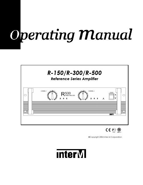
Copyright 2004 Inter-M CorporationContents Welcome (3)Unpacking (3)Warnings (3)Operation (5)Features (6)Front Panel Controls (7)Operational Modes (11)Speaker Impedance and Connections (11)Speaker Connection Procedures (12)Speaker Cable (13)Maintaining Proper Polarity (13)Rack Mounting Your Amplifier (13)Block Diagram (14)Specifications (15)2WelcomeA personal welcome to you from the management and employees of Inter-MThank you for purchasing this fine Inter-M product. All of us here at Inter-M are dedicated to providing you with the highest quality products and the best value.We sincerely trust this product will provide you with years of satisfactory service, but if anything is not to your complete satisfaction, we will endeavor to make things right.Welcome to Inter-M, and thank you for becoming a part of our worldwide extended family!UnpackingAlthough your R-150/R-300/R-500 Reference Series Amplifier is neither complicated nor difficult to operate, we recommend you take a few minutes to read this brief manual and familiarize yourself with the important information regarding product features, setup and operation.As with most electronic devices, we strongly recommend you retain the original packaging. In the unlikely event the product must be returned for servicing, the original packaging (or reasonable equivalent) is required.WarningsEnvironmentNever place this product in an environment that could alter its performance or reduce its service life. Such environments are usually characterized by high levels of heat, dust, moisture, or vibration.Safety1. Read these instructions carefully.2. Follow all instructions.3. Keep all warnings.4. Do not operate this apparatus near water.5. Clean only with a damp cloth.6. Do not block any of the ventilation openings.7. Install only in accordance with the instructions in this manual.38. Do not install near any heat sources such as radiators, heat registers, stoves, or other devices (including amplifiers) that produce heat.9. Do not defeat the safety purpose of the polarized or grounding type plug. A polarized plug has two blades, with one wider than the other. A grounding type plug has two blades and a third grounding prong. The wide blade or the third prong is provided for your safety. If the provided plug does not fit into your outlet, consult an electrician for replacement of the obsolete outlet.10. Protect the power cord from being walked on or pinched, particularly at plugs, convenience receptacles, and the point where it is attached to the apparatus.11. Use only the attachments/accessories specified.12. Use only with a cart, stand, tripod, bracket, or table specified, or sold with the apparatus. When a cart is used, use caution when moving the cart/apparatus combination to avoid overturning.13. Unplug this apparatus during lightning storms or when unused for long periods of time.14. Refer all servicing to qualified service personnel. Servicing is required when the apparatus has been damaged in any way, such as power supply cord or plug is damaged, liquid has been spilled or objects have fallen into the apparatus, the apparatus has been exposed to rain or moisture, does not operate normally, or has been dropped.4OperationMake certain that speakers and input sources are properly connected before switching AC Mains power on.Keep volume levels at minimum gain before switching on.NOTE: The system’s operation is delayed by approximately three seconds after pressing the AC Mains power switch. This is due to the built-in protection circuitry, designed to protect speakers and other system components.5R-150/R-300/R-500Power AmplifierFeaturesHigh Performance Monitor Amp• Studio quality monitor amp provides clean sound for the studio, conference room, concert hall and commercial installations.Advanced Protection Circuitry• Thermal and current overload protection, short and open circuit protection, power-on delay, for component and loudspeaker protection.Ultra-Efficient Cooling System• Convection cooling uses no fan, providing ultra-quiet performance in critical applications.Bridged Mono and Input Parallel Operation• Bridged mono and input parallel modes for increased power and versatility.Versatile Connectivity• Balanced and unbalanced inputs on XLR and 1/4” phone connectors, as well as speaker connect and five-way binding post output connectors to accommodate a wide array of system options.LED Indicators• Front panel LED indicators show power, clip, protection and level status.6Front Panel Controls1. Power SwitchPushing this switch up swiches the unit on. Pushing it down swiches the unit off.2. Power Indicator LEDWhen the unit is switched on, the Power LED will glow steadily.3. Protection IndicatorsThere are two protection indicator LEDs – one LED for Channel 1 of the amplifierand one LED for Channel 2. These LEDs indicate the state of the amplifier’sprotection circuitry. When the Protection LED is on (illuminated), the protectioncircuitry is active, indicating that the unit is not operating normally. This is typically due to overheating or power limiting. Please check the Input and Outputcondition of the amplifier.(Note that the Protection Indicators light for approximately six seconds when the amplifier is first switched on.)The amplifier offers the following modes of protection:Thermal Protection: Activates when internal operating temperature exceeds 100˚Celsius.Compressor/Limiting: When maximum output power is reached, output level will be reduced to avoid distortion.DC Fault Protection: DC detection circuitry shuts the speaker output when a DCfault voltage of ±3dB or greater is detected.Power On/Off Muting: Audio to speakers is delayed for several seconds onpowering on and off to reduce potential speaker damage from transients.74. Input AttenuatorsThese are detented controls for regulating each channel’s input level. Clockwise rotation increases gain.5. HandlesUse these handles to easily move the amplifier.6. Clip IndicatorsThe red CLIP LED indicates an excessive output level, lighting when distortionreaches approximately 1%. Do not operate the unit with the CLIP LED steadilyilluminated.7. Output Level IndicatorsThe LEVEL LED indicates the amplifier’s output status, lighting when audio signalreaches –15dB.8Rear Panel Controls1. Speaker Output TerminalsThese five-way binding posts and speaker connect jacks are used to connectspeakers to the unit.Speakers may be connected in Stereo or Bridged Mono mode. Please refer to the illustrations below. When connecting speakers in Bridged Mono mode, use theChannel 1 “+“ output for the positive lead, and the Channel 2 “+“ for thenegative lead.2. AC ConnectorConnect the supplied standard AC input cable here.3. Mono/Stereo Mode SelectorUse this slide switch to select either Stereo or Bridged Mono operation. WhenBridged Mono mode is selected, only Channel 1 is active. Use the Channel 1Input Attenuator to set input level, and refer to the corresponding indicator LEDsfor operating status.94. Input ConnectorsBalanced input connectors are provided on XLR jacks, while unbalancedconnections can be made using the 1/4” phone jacks. (When operating inBridged Mono mode, only Channel 1 input is active.)5. Heat SinkHeat is emitted via the external HEAT SINK when the amplifier is switched on.When the amplifier is rack mounted, we recommend that you keep the rear of the rack open in order to release heat.10Operational ModesStereo ModeIn Stereo mode, channels A and B operate independently, with each channel feeding its own amplifier circuit. In this mode, minimum speaker impedance per channel is 4Ω. Bridged Mono ModeIn Bridged Mono mode, both amplifier channels are bridged together and function as a single-channel amplifier. Only the Channel 1 input is active, and only the Channel 1 Input Attenuator controls the amp’s output. In this mode, minimum speaker impedance per channel is 8Ω.Speaker Impedance and ConnectionsThe minimum speaker impedance is wholly dependent on the operational mode of the amplifier. It is critical that the minimum impedance not equal less than the recommended impedance.Speaker Connection ProceduresAlways switch the power off before connecting speakers.After removing approximately 10mm (1/4 inch) of insulation from the ends of the speaker cables, twist the strands tightly and pass the bare ends through the holes in the terminals, tightening the terminals to secure the wires.Make certain the wires do not protrude from the terminals and touch the amplifier’s chassis, or an adjacent terminal.The R-150/R-300/R-500 is capable of very high output levels. Be certain to use a speaker system that can accept high input levels. If the input capacity of your speaker system is less than the amplifier’s rated output, you may protect your speakers by connecting a fuse between amplifier and speaker, as shown below:Use the following formula to determine the needed fuse rating:Po (W) = Speaker’s continuous input capacity (RMS)R (Ω) = Speaker’s nominal impedanceI = Required fuse rating.For example: if the speaker’s input capacity is 100W, with 8Ω impedance,The required fuse rating is 3.5A.Speaker CableAlways use the heaviest-duty (lowest gauge) speaker cable available. The terminals can accommodate very thick speaker cable.Maintaining Proper PolarityIt is very important to wire your speaker connectors consistently at each end of eachcable, in order to maintain proper polarity. All quality cables are manufactured with clear markings to identify the different conductors – normally by color-coding,printed markings, or textured ribbing on the cable’s jacket material. Always makecertain to correctly wire your connections so that tip is connected to tip, and sleeve to sleeve. Failing to do so will cause your speakers to operate out of phase, resulting in significantly reduced low-frequency output from your system.Rack Mounting Your AmplifierThe amplifier expels heat through the rear panel heat sink. When mounting in a portable equipment rack, maintain adequate ventilation by making certain the front and rear panels are not obstructed.Block DiagramSpecificationsRated Output (RMS)R-500 R-150R-300Stereo 8Ω, 1kHz (per channel) 50W 100W 170WStereo 4Ω, 1kHz (per channel) 75W 100W 250WBridged Mono 8Ω, 1kHz 150W 300W 500WFrequency Response ( ± 0.5dB) 20Hz-50kHzInput Sensitivity 0.775V(balanced)Input Impedance 10kT.H.D < 0.03%S/N -105dBFactor > 100DampingSlew Rate ± 30V/µ sec.Protection Switch On Delay, Thermal,DC Fault, PC LimiterGENERALPower Source AC 110V-240V, 50/60Hz,Power Consumption140WR-150210WR-300R-500 330WWeightR-150 7.5kg/16.5lb8.2kg/18lbR-300R-500 13.6kg/29.9lbDimensions210(D)xmmx88(H)R-150/R-300 482(W)8.3(D)inchesx19(W)3.5(H)x280(D)mmx132(H)xR-500 482(W)19(W) x 5.2(H) x 11(D) inchesSpecifications and design subject to change without notice for improvements.Inter-M, Ltd. (Korea) began operations in 1983.Since then, Inter-M has grown to become one of the largest manufacturersof professional audio and commercial sound electronics equipment in the world.Inter-M has gained worldwide recognition for its own branded products,as well as private label manufacturing of electronics sold under other names (OEM).The company is no longer just a Korean company, but rather a global companythat is truly international in scope, with factories and offices in Korea and China,and sales and marketing operations located in Japan, Europe, and the U.S.A.With more than 850 employees around the globe, Inter-M is well-poised for further growth and expansion.INTER-M AMERICAS, INC.1 EAST BEACON LIGHT LANE, CHESTER, PA, USA 19013-4409TEL: (610) 874-8870, FAX: (610) 874-8890HomePage:,E-mail:*******************INTER-M CorporationSEOUL OFFICE: 653-5 BANGHAK-DONG, DOBONG-KU, SEOUL, KOREATEL: 82-2-2289-8140~8, FAX: 82-2-2289-8149HomePage:,E-mail:******************KOREA 0704R150300500 PRINTEDIN。
M4A88T-M_LE主板详细说明书

之損害。 B. 自行拆裝、修理、或將產品送至非華碩認証之維修點進行檢測維修。 C. 用戶擅自或請第三人修改、修復、變更規格及安裝、添加、擴充非本公司原廠銷售、授權
用戶名稱
購買日期
用 聯繫人
戶 聯繫地址
填 經銷商名稱
寫 資 產品型號
料
經
銷
商
印
章
聯繫電話
產品種類.......................................................................................................................... viii 電氣方面的安全性......................................................................................................... viii 操作方面的安全性......................................................................................................... viii 華碩 REACH................................................................................................................... viii
二、 華碩公司對在中國大陸地區(不包括港澳台地區)發售的、經合法渠道銷售給消費者的華碩主 板及顯卡產品實行三年的免費保修服務。
PW-845LVA工业电脑主板 产品说明书

Manual for PW-845LVA
Page 3 of 35
附件清单
请完整的检查你的产品包装,如果发现有损坏或缺失的物件,请与
你的供应商联系。
■
PW-845LVA主板
×1
■
产品说明手册
×1
■
产品保修卡
×1
■
驱动程序光盘
×1
■
miniIDE数据线
×1
■
串口转接线
×1
■
并口转接线
×1
■
音频转接线
×1
Manual for PW-845LVA
Page 2 of 35
2.1.11 miniPCI接口------------------------------------13 2.1.12 miniIDE接口------------------------------------14 2.1.13 CF卡接口---------------------------------------14 2.1.14 鼠标/键盘扩展接口------------------------------15 2.1.15 PC104plus接口----------------------------------15 2.1.16 红外接口---------------------------------------16 2.1.17 SMBUS接口--------------------------------------16 2.1.18 CD-IN接口--------------------------------------17 2.2 跳线设置 2.2.1 清除CMOS跳线-----------------------------------18 2.2.2 COM3/4供电选择跳线-----------------------------18 2.2.3 COM2传输方式选择-------------------------------19 2.2.4 看门狗设置-------------------------------------20 2.2.5 USB供电模式选择--------------------------------20 第三章 BIOS设置 3.1 主菜单---------------------------------------------21 3.2 标准CMOS功能---------------------------------------22 3.3 高级BIOS功能---------------------------------------23 3.4 高级芯片组功能-------------------------------------24 3.5 整合外围设备---------------------------------------25 3.6 电源管理设备---------------------------------------26 3.7 PnP/PCI Configurations-----------------------------29 3.8 PC健康状态-----------------------------------------29 3.9 频率电压控制---------------------------------------30 3.10 载入优化或默认设置---------------------------------31 3.11 设置管理员和用户密码-------------------------------32 第四章 驱动光盘说明--------------------------------------33
aemh81-814 824 工业级主板 用户手册说明书
AEMH81-814 AEMH81-824 Intel® H81 Express Chipset 工业级主板用户手册User's ManualRev: 2.8Date: 2017.07安全指导01. 务必请仔细通读本安全指导。
02. 务必请妥善保管本手册,以备将来参考。
03. 请保持本设备的干燥。
04. 机箱的开口缝隙是用于通风避免机箱内的部件过热,请勿将此类开口掩盖或堵塞。
05. 在将本设备与电源连接前,请确认电源电压值,将电压调整为110V/220V。
06. 请将电源置于不会被践踏到的地方,并且不要在电源线上堆置任何实物。
07. 插拔任何扩展卡或设备模块前,请将电源线拔下。
08. 请留意手册上提到的所有注意和警告事项。
09. 通电之前请确认主机箱中不要遗留螺丝等金属物件,以免电气短路烧毁其他部件。
10. 不得将任何液体倒入机箱开口的缝隙中,否则会产生严重损坏或电路瘫痪。
11. 如果发生以下情况,请找专业人员处理:a. 电源线或插头损坏b. 液体渗入机器内c. 机器暴露在潮湿的环境中d. 机器工作不正常或用户不能通过本手册的指导使其正常工作e. 机器跌落或受创f. 机器有明显的破损迹象商标声明所有的品牌,产品,徽标,商标和公司名称都是属于商标或注册商标各自的拥有者。
AMI®是AMI公司的注册商标。
Intel®,Celeron®,Pentium®是Intel 公司的注册商标。
Netware®是Novell Inc.的注册商标。
PS/2和OS/2是International Business Machines公司的注册商标。
Windows® 98/2000/NT/XP和Microsoft®是Microsoft 公司的注册商标。
目录安全指导 (1)商标声明 (1)第一章主板简介及规格说明 (4)1.1包装盒内物品清单 (4)1.2工业级主板特色 (4)1.3主板规格简述 (5)1.4主板LAYOUT图及规格表 (6)1.4.1AEMH81-814主板布局图 (6)1.4.2AEMH81-824主板布局图 (7)1.4.3主板规格 (8)第二章硬件设备的安装说明 (10)2.1中央处理器的安装(以1150为例) (10)2.2CPU风扇的安装 (11)2.3内存的安装 (13)2.4视频采集卡的安装 (13)2.5主板跳线的设定说明 (14)2.5.1清除CMOS跳线(CLR_CMOS) (14)2.5.2LVDS电压控制跳线(LVDS_PWR) (14)2.5.3AUTO_ON接口状态选择跳线 (15)2.5.4COM1 / COM2状态控制跳线(JP14 / JP15 / JP16 / JP17) (15)2.5.5COM6与JP8,COM7与JP9功能选择跳线(JP16 / JP17)(仅AEMH81-824) (15)2.6主机板接头说明 (15)2.6.1风扇电源接头 (CPU_FAN1 / SYS_FAN1/2) (15)2.6.2USB扩展接头 (16)2.6.3前置音效输出接口(F_AUDIO1) (16)2.6.4COM插针 (17)2.6.5COM插针的接线方法 (17)2.6.6SATA接口使用说明 (18)2.6.7系统信号 / 控制面板接口(F_PANEL1) (18)2.6.8INVERT 针脚定义(LVDS背光控制接口) (19)2.6.9LVDS针脚定义 (19)2.6.10RS422 / RS485传输接口插针定义(JP8/9)(仅AEMH81-824) (20)2.6.11DEBUG 针脚定义(DEBUG) (21)2.6.12ATX电源接口安装(ATX_12V1 / ATXPWR1) (21)2.6.13AUTO_ON插针定义 (22)2.6.14清除CLR_CMOS1插针定义 (22)第三章BIOS简介 (24)3.1BIOS升级更新 (24)3.2BIOS设定 (24)3.3上电自动开机功能设置方法 (25)第四章看门狗软件使用说明及安装步骤 (27)4.1软件功能 (27)4.2看门狗定义及工作原理 (27)4.3软件安装 (27)第五章驱动程序安装 (29)5.1芯片组驱动程序的安装 (29)5.2板载显卡驱动的安装 (29)5.3板载声卡驱动的安装 (29)5.4板载网卡驱动的安装 (29)5.5Intel管理引擎界面的安装 (29)5.6USB3.0 驱动的安装 (30)第一章主板简介及规格说明为了保证产品品质并适合市场需求,主板都通过了抗老化、低电压、各种温度、湿度环境下的反复测试,并通过市面多款主流视频采集压缩卡的兼容性测试,均能满足行业的需求。
intel m10 电源管理用户指南说明书

Intel® MAX® 10电源管理用户指南本翻译版本仅供参考,如果本翻译版本与其英文版本存在差异,则以英文版本为准。
某些翻译版本尚未更新对应到最新的英文版本,请参考英文版本以获取最新信息。
在线版本ID: 683400内容内容1. MAX® 10电源管理概述 (3)2. MAX 10电源管理功能和体系结构 (4)2.1. 电源器件选项 (4)2.1.1. 单电源器件 (4)2.1.2. 双电源器件 (4)2.1.3. MAX 10电源器件选项对比 (5)2.1.4. 电源设计 (5)2.2. 上电复位电路 (6)2.2.1. POR电路监控和未监控电源 (7)2.2.2. 即时启动支持 (8)2.3. 电源管理控制器方案 (8)2.3.1. 电源管理控制器体系结构 (8)2.4. 热插拔 (10)2.4.1. 热插拔规范 (10)2.4.2. 热插拔功能的实现 (11)3. 电源管理控制器参考设计 (12)3.1. 时钟控制模块 (13)3.2. I/O缓冲器 (13)3.3. 内部振荡器 (13)3.4. 电源管理控制器 (13)3.4.1. Entering状态 (14)3.4.2. 睡眠状态 (14)3.4.3. Exiting状态 (14)3.4.4. 唤醒状态 (14)3.5. 进入或退出睡眠模式 (14)3.5.1. 进入睡眠模式 (14)3.5.2. 退出睡眠模式 (15)3.5.3. 时序参数 (15)3.6. 硬件实现和电流测量 (16)A. MAX 10 Power Management User Guide存档 (18)B. MAX 10电源管理用户指南附加信息 (19)B.1. MAX 10电源管理用户指南文档修订历史 (19)1. MAX® 10电源管理概述MAX® 10器件提供下列电源器件选项:•单电源供电器件—需要1个3.0 V或3.3 V外部电源,以提供最大便利性和电路板简洁性。
华擎主板说明书

注意!倘若本產品上之產品序列號有所破損或無法辨識者,則該項產品 恕不保修!
目錄內容
安全性須知. ...................................................................................................................6 電氣方面的安全性. ...........................................................................................6 操作方面的安全性. ...........................................................................................6 關于這本用戶手冊. .....................................................................................................7 用戶手冊的編排方式.......................................................................................7 提示符號 . ..........................................................................................................7 跳線帽及圖標說明. ...........................................................................................8 哪裡可以找到更多的產品信息. ....................................................................8 M2N-VM DVI 規格列表. .......................................................................................10
【精品文档】2019年某公司亚特M50CA放电加工机操作说明书

亚特M50CA放电加工机操作说明书1.目的使每位员工对机台能够有正确的认识,熟悉机台的性能,进而发挥机台的最大功能.2.适用范围现有放电加工所使用的M50CA机台.3.主要职责与权限3.1 课长: 计划并督促各小组认真学习并严格执行此规范3.2 组长: 对加工者进行教育训练,带领执行且在实践中指导加工者按此规范作业3.3 加工者: 确定按此规范操作4.程序内容4.1 系统启动: 本型机台以内部硬盘开机具体步骤如下4.1.1 将主电源按钮至ON4.1.2 按下红色启动开关 (Power )4.1.3 等待屏幕显示出开机画面后,再将紧急开关顺时针扭至开状态4. 2 画面解说: 初始画面可根据加工需求选择相应模式组工作,现对各模式组画面解说如下:主画面操作方法开机后屏幕下方会显示:F1 F2 F3 F4 F5操作手动 E档案系统诊断4.2.1 手动画面操作: 按F2进入手动画面操作4.2.1.1 寻找参考点,按F1进行X、Y、Z方向参考点寻找4.2.1.2 寻找内孔中心,按F2进行各平面的内孔中心寻找4.2.1.3 寻边:按F3进行X、Y、Z轴正负方向的寻边4.2.1.4 寻外孔中心,按F4进行外孔中心寻找4.2.1.5 寻角落,按F5进行外孔中心寻找4.2.1.6 定点位移,按F6进行X、Y、Z轴定坐标移动4.2.1.7 坐标设定,按F7设定X、Y、Z轴坐标值4.2.1.8 1/2XY,按F8将X、Y值除以24.2.2 操作画面:在开机画面下按F1进行操作画面4.2.2.1 建新程序:按F1进行新程序编辑4.2.2.2 修改:按F2可将光标所处的行,进行修改4.2.2.3 插入:按F3可在光标所处的行后插入程序行(所要插入内容)4.2.2.4 删除:按F4可将光标所处行删掉4.2.2.5 拷贝:按F5可将标记内部分进行标记区分4.2.2.6 标记:按F6可将一般程序行进行标记区分4.2.2.7 不标记:按F7可将标记的部分取消标记4.2.2.8 档案:按F8进入档案画面4.2.2.9 加工:按F9可行程序加工4.2.2.10离开:按F10离开操作画面,回到开机画面4.2.3 系统操作:在开机画面下按F4进行系统操作,一般情况下用F5、F6、F7进行X、Y、Z归零动作4.2.4 诊断:维修人员可使用4. 3 子画面操作4.3.1 在操作画面下F8档案有以下模式4.3.1.1 载入:按F1进入程序名称档案系列,可进行程序的调出或查找.4.3.1.2 存档:按F2将显示在画面上程序或修改后的程序存盘4.3.1.3 存新檔:按F3将显示在画面上的程序存入另一不同的文件名称中4.3.1.4 拷贝:按F4将程序重制一份或多份4.3.1.5 删除:按F5可将档案中的程序删除4.3.2 在操作画面下,F3插入以下子模式4.3.2.1 坐标:按F1可进行参考点寻长和三轴坐标设定4.3.2.2 寻边:按F21) 可进行三轴寻边动作2) 内孔中心或外边孔中心寻找3) 角落对刀4.3.2.3 位移:按F3可进行三轴的坐标移动编辑4.3.2.4 加工:按F4可进行三轴中任一轴(二轴或三轴)的直线加工4.3.2.5 行星:按F5可以进行圆孔、方孔等的摇摆方式加工4.3.2.6 杂项:按F6可选择暂停动作. (暂未用到)4.3.2.7 子程序:按F7进行子程序的呼叫4.3.2.8 开关:按F8可选择开关油泵等机械部分开关动作4.3.2.9 离开:按F10回上一画面模式4. 4 关机4.4.1 先将紧急制动开关压下4.4.2 将电源开关关至“OFF”状态4.4.3 关机后不得马上开机,需待2至3分钟5.附页亚特机台加工方案亚特机台加工方案尺寸基本单位为 MM1. 放电面积在60*60至80*80A450-14: 放电尺寸间隙: 0.180 余量间隙:0.360A210-14: 0.130 0.280A120-11: 0.100 0.200A090-08: 0.080 0.150A060-12: 0.070 0.125A045-14: 0.060 0.110A045-10: 0.050 0.080精度±0.02 A045-09: 0.045 0.0702. 放电面积在50*50至60*60A300-13: 放电尺寸间隙: 0.150余量间隙:0.300A150-12: 0.1200.200A090-10: 0.090 0.160A060-13: 0.075 0.130A045-13: 0.070 0.105A045-11: 0.055 0.090A045-09: 0.0450.070A030-07: 0.032 0.032A030-04: 0.027 0.0273.放电面积在35*35至50*50A210-13: 放电尺寸间隙: 0.120 余量间隙:0.250A120-11: 0.090 0.180A090-08: 0.080 0.150A060-12: 0.070 0.125A045-11: 0.045 0.090精度±0.02 A030-11: 0.0350.070精度±0.01 A030-10: 0.0300.0604.放电面积在25*25至35*35A150-12: 放电尺寸间隙: 0.120 余量间隙:0.220A090-10: 0.090 0.160A060-13: 0.075 0.130A045-14: 0.060 0.110A030-14: 0.050 0.085A030-13: 0.040 0.075A030-11: 0.035 0.070A030-09: 0.033 0.055A030-08: 0.025 0.050 精度±0.02 A020-06: 0.028 0.028精度±0.01 A020-04: 0.025 0.0255.放电面积在15*15至25*25之间A120-11: 放电尺寸间隙: 0.120 余量间隙:0.200A060-13: 0.090 0.130A045-14: 0.0600.110A030-13: 0.040 0.075A030-11: 0.035 0.070A030-09: 0.033 0.055A020-09: 0.028 0.045精度±0.02 A020-08: 0.0250.040精度±0.01 A020-04: 0.0250.030A015-04: 0.0220.0226.放电面积在10*10至15*15A090-10: 放电尺寸间隙: 0.090 余量间隙:0.160A060-12: 0.070 0.125A045-14: 0.060 0.110A045-11: 0.055 0.090A030-11: 0.035 0.070A020-11: 0.030 0.050 精度±0.02 A020-07: 0.0300.030精度±0.01 A020-04: 0.0250.035A015-04: 0.022 0.022 7.放电面积在8*8至10*10A090-10: 放电尺寸间隙: 0.090 余量间隙:0.160A060-12: 0.070 0.125A045-14: 0.060 0.110A030-11: 0.035 0.070精度±0.02 A020-07: 0.0300.030精度±0.01 A020-04: 0.0250.030A015-04: 0.022 0.0228.放电面积在5*5至8*8A060-12: 放电尺寸间隙: 0.070 余量间隙:0.125A045-14: 0.060 0.110A030-11: 0.035 0.070 精度±0.02 A020-07: 0.0300.030精度±0.01 A020-04: 0.0250.030A014-04: 0.022 0.022 9.放电面积在3*3至5*5A045-14: 放电尺寸间隙: 0.060 余量间隙:0.110A030-11: 0.035 0.070A020-07: 0.030 0.050 精度±0.02 A015-08: 0.0250.025精度±0.01 A010-08: 0.0240.024A010-06: 0.019 0.01910.放电面积在1.5*1.5至3*3A030-11: 放电尺寸间隙: 0.038 余量间隙:0.070A020-10: 0.033 0.050A015-9: 0.028 0.040 精度±0.02 A010-8: 0.024 0.024精度±0.01 A010-5: 0.019 0.01911.放电面积在1.5*1.5以下A020-11: 放电尺寸间隙: 0.035 余量间隙:0.060A015-8: 0.025 0.045A010-7: 0.022 0.033 精度±0.02 A010-4: 0.018 0.018精度±0.01 A005-4: 0.017 0.017。
MSI MS-98K9 V2.1工业级计算机板用户手册说明书
Industrial Computer Boardi1Thank you for choosing the MS-98K9 V2.1, an excellent industrialcomputer board.Based on the innovative Intel®Coffee Lake-S & Coffee Lake Refresh-SProcessor, the MS-98K9 V2.1 is engineered to provide reliableperformance for a wide variety of industrial applications.1-1-11-5Rear Panel S/PDIF Box HeaderPCIe Slots USB 2.0 Port GPIO Box HeadersParallel Port Box Header COM Port Box Headers & Power Jumpers Front Audio Box Header M.2 Key M SlotPCI SlotPCI SlotPCI Power Jumper PCI Power JumperD-SUB (VGA) Port GbE RJ45 Port USB 3.2 Gen 2 Ports Line-InMouse/Keyboard Combo Port USB 2.0 Ports DisplayPorts Line-Out Mic-In HDMI Port GbE RJ45 Port USB 3.2 Gen 2 Ports GbE RJ45 Port USB 3.2 Gen 2 Ports2This chapter provides you with the information about hardwaresetup procedures. While doing the installation, be careful in holdingthe components and follow the installation procedures. For somecomponents, if you install in the wrong orientation, the components willnot work properly.Use a grounded wrist strap before handling computer components. Staticelectricity may damage the components.2-2-12-2MS-98K9 V2.12-4MS-98K9 V2.12-6MS-98K9 V2.12-8D-SUB (VGA) PortUSB 3.2 Gen 2 Ports USB 2.0 PortsDisplayPortsLine-Out Mic-In HDMI Port USB 3.2 Gen 2 Ports USB 3.2 Gen 2 Portsh Mouse/Keyboard Combo PortThe standard PS/2® mouse/keyboard DIN connector is for a PS/2® mouse/keyboard.h D-SUB (VGA) PortThe DB15-pin female connector is provided for monitor.h HDMI PortThe High-Definition Multimedia Interface (HDMI) is an all-digital audio/video interface capable of transmitting uncompressed streams. HDMI supports all TV2-203This chapter provides information on the BIOS Setup program and allowsusers to configure the system for optimal use.Users may need to run the Setup program when:■An error message appears on the screen at system startup and requests users to run SETUP.■Users want to change the default settings for customized features.• Please note that BIOS update assumes technician-level experience.• As the system BIOS is under continuous update for better system performance, the illustrations in this chapter should be held forreference only.2-3-13-2MS-98K9 V2.1MainUse this menu for basic system configurations, such as time, date, etc.AdvancedUse this menu to set up the items of special enhanced features.BootUse this menu to specify the priority of boot devices.SecurityUse this menu to set supervisor and user passwords.ChipsetThis menu controls the advanced features of the onboard chipsets.PowerUse this menu to specify your settings for power management.Save & ExitThis menu allows you to load the BIOS default values or factory default settings into the BIOS and exit the BIOS setup utility with or without changes.3-4MS-98K9 V2.1 System DateThis setting allows you to set the system date. The date format is <Day>, <Month><Date> <Year>.System Timesetting allows you to set the system time. The time format is <Hour><Minute> <Second>.SATA Mode SelectionThis setting specifies the SATA controller mode.PCIe Storage DeviceThis setting controls the Intel® RST (Rapid Storage Technology) support for PCIe storage devices. Setting to RST Controlled will enable Intel® Optane™ Memory. Since PCIe storage devices can’t be recognized by Intel® RST in AHCI mode, please set SATA Mode Selection to RAID to enable RST support forstorage devices.Full Screen Logo DisplayThis BIOS feature determines if the BIOS should hide the normal POST messages with the motherboard or system manufacturer’s full-screen logo.When it is enabled, the BIOS will display the full-screen logo during the boot-up sequence, hiding normal POST messages.When it is disabled, the BIOS will display the normal POST messages, instead of the full-screen logo.Please note that enabling this BIOS feature often adds 2-3 seconds of delay to the booting sequence. This delay ensures that the logo is displayed for a sufficient amount of time. Therefore, it is recommended that you disable this BIOS feature for a faster boot-up time.Bootup NumLock StateThis setting is to set the Num Lock status when the system is powered on. Setting to [On] will turn on the Num Lock key when the system is powered on. Setting to [Off] will allow users to use the arrow keys on the numeric keypad.Option ROM Messagesitem is used to determine the display mode when an optional ROM initialized during POST. When set to [Force BIOS], the display mode used AMI BIOS is used. Select [Keep Current] if you want to use the display mode of 3-6MS-98K9 V2.1 Intel Virtualization TechnologyVirtualization enhanced by Intel Virtualization Technology will allow a platformto run multiple operating systems and applications in independent partitions.virtualization, one computer system can function asActive Processor CoresThis setting specifies the number of active processor cores.Intel(R) SpeedStep(tm)(Enhanced Intel SpeedStep Technology) allows the systemadjust processor voltage and core frequency, which can result in decreased average power consumption and decreased average heat production. When disabled, the processor will return the actual maximum CPUID input value ofthe processor when queried.controls the C-State (CPU Power state). C-Stateindicates the ability to run the processor in lower power states when the PC is idle. This setting enables/disables the C-State Configuration for power savingSerial Port 1 ~ Serial Port 6This setting enables/disables the specified serial port.Change SettingsThis setting is used to change the address & IRQ settings of the specifiedMode SelectSelect an operation mode for the specified serial port.Parallel PortThis setting enables/disables the parallel port.Change SettingsThis setting is used to change the address & IRQ settings of the parallelDevice ModeSelect an operation mode for the parallel port.Watch Dog TimerYou can enable the system watch-dog timer, a hardware timer that generatesa reset when the software that it monitors does not respond as expected eachtime the watch dog polls it.This setting controls the FIFO data transfer mode.Shared IRQ ModeThis setting provides the system with the ability to share interrupts among its 3-8Smart Fan ConfigurationCPUFAN1, SYSFAN1 ~ SYSFAN3enables/disables the Smart Fan function. Smartexcellent feature which will adjust the CPU/system fan speed automatically depending on the current CPU/system temperature, avoiding the overheating to damage your system.PCI/PCIE Device ConfigurationLegacy USB SupportSet to [Enabled] if you need to use any USB 1.1/2.0 device in the operating system that does not support or have any USB 1.1/2.0 driver installed, such as DOS and SCO Unix.Audio ControllerThis setting enables/disables the onboard audio controller.Launch OnBoard LAN OpROMsettings enable/disable the initialization of the onboard/onchip Boot ROM during bootup. Selecting [Disabled] will speed up the boot process.GPO0 ~ GPO7These settings control the operation mode of the specified GPIO.CSM Supportsetting enables/disables the support for Compatibility Support Module, part of the Intel Platform Innovation Framework for EFI providing the capability to support legacy BIOS interfaces.Boot Option Prioritiessetting allows users to set the sequence of boot devices where attempts to load the disk operating system.Administrator PasswordAdministrator Password controls access to the BIOS Setup utility.User PasswordPassword controls access to the system at boot and to the BIOS Chassis IntrusionThe field enables or disables the feature of recording the chassis intrusion status and issuing a warning message if the chassis is once opened.Intel Trusted Execution TechnologyIntel Trusted Execution Technology provides highly scalable platform security in physical and virtual infrastructures.Intel BIOS Guard SupportIntel BIOS Guard Support ensures that updates to system BIOS flash are secure.ME Firmware Version, ME Firmware Mode, ME Firmware SKU, ME Firmware Status 1, ME Firmware Status 2These settings show the firmware information of the Intel ME (ManagementThis setting enables/disables the ME status.Manageability Features StateThis setting enables/disables the Manageability Features State.AMT BIOS FeaturesThis setting enables/disables the AMT BIOS Features.AMT ConfigurationIntel Active Management Technology (AMT) is hardware-based technology for remotely managing and securing PCs out-of-band.ME FW Image Re-FlashThis setting enables/disables the ME FW image reflash.PTT ConfigurationIntel Platform Trust Technology (PTT) is a platform functionality for credential storage and key management used by Microsoft Windows.Anti-Rollback SVN ConfigurationSecurity Device SupportThis setting enables/disables BIOS support for security device. When set to [Disable], the OS will not show security device. TCG EFI protocol and INT1A interface will not be available.SHA-1 PCR Bank, SHA256 PCR BankThese settings enable/disable the SHA-1 PCR Bank and SHA256 PCR Bank. Pending OperationSecurity Device Support is set to [Enable], Pending Operation appear. Set this item to [TPM Clear] to clear all data secured by TPM or [None] to discard the selection. It is advised that users should routinely back up their TPM secured data.Platform Hierarchy, Storage Hierarchy, Endorsement HierarchyThese settings enable/disable the Platform Hierarchy, Storage Hierarchy and Endorsement Hierarchy.TPM2 0 UEFI Spec Version, Physical Presence Spec VersionThis settings show the TPM2.0 UEFI Spec Version and Physical PresenceConsole RedirectionRedirection operates in host systems that do notand keyboard attached. This setting enables/disables the operation of console redirection. When set to [Enabled], BIOS redirects and sends all contents that should be displayed on the screen to the serial COM port for display on the terminal screen. Besides, all data received from the serial port is interpreted as keystrokes from a local keyboard.Console Redirection SettingsTerminal TypeTo operate the system’s console redirection, you need a terminal supporting ANSI terminal protocol and a RS-232 null modem cable connected between。
Intel商品说明文档说明书

An EvoTM Design
In the new work-everywhere environment, technology plays a major role in the employee experience.
72% of employees surveyed rank listening to employees and finding out what they need as the best way to improve employee experience. When it comes to technology purchases, including employees in decision-making and device selection is a win-win that turns technology refreshes into an investment in employee morale.1
Multiple 4K Monitor Support
With Thunderbolt™ 4, you can connect multiple 4K monitors, transfer files and charge your PC with one universal cable10
Choice of Accessories
Quick-charging in only 30 minutes for 4-hour charge on FHD displays to help your team get more done7
Superior Quality Videoconferencing
With background blur, noise suppression, face framing and lighting correction, your team will always look and sound their best
Arbor Technology ITX-i89H0 Mini-ITX 工业级母板说明书

ITX-i89H0Mini-ITX Industrial MotherboardQuick Installation GuideCopyright© All Rights Reserved.4041890001110P♦ Technical SupportIf you have any technical difficulties, please consult the user’s manual or contact us at: https:///♦ Declaration of ConformityFCC Class AThis device complies with Part 15 of the FCC Rules. Operation is subject to the following two conditions : (1) this device may not cause harmful interference, and (2) this device must accept any interference received, including interference that may cause undesired operation.Before you begin to install your single board, please make sure that the following materials have been shipped:1 x ITX-i89H0 Mini-ITX industrial motherboard1 x Cooler1 x Driver CD1 x Quick Installation GuideIf any of the above items is damaged or missing, contact your vendor immediately.motherboard2 x SATA cables1 x SATA Power cable1 x COM cable1 x USB cable1 x USB 3.0 cableThe Installation Paths of CD DriverWindows 8.1&10 (64-bit)Driver PathCHIPSET\i89X\Chipset\Chipset_10.1.1.13_PublicGRAPHIC\i89X\Graphic\IntelR Graphics Driver Production Version 15.40.16.64.4364 ETHERNET\i89X\EthernetAUDIO\i89X\Audio\7687_PG436_Win10_Win8.1_Win8_Win7_WHQLx64ME\i89X\ME\Intel(R)_ME_11.0_Corporate_11.0.0.1202USB3.0\i89X\USB3.0\win8.1 64bit\Intel_USB_3.0_xHC_Adaptation_Driver_MR1_Re-lease_1.0.1.45_PVRAID\i89X\RAID\Intel Rapid Storage Technology Driver 14.8.0.1042SpecificationsBoard DimensionsUnit: mmJumpers/Connectors Quick ReferenceJumpersLabel FunctionJPCH1Clear CMOS Selection JME1ME Selection ConnectorsLabel FunctionUSB2USB3.0/2.0 connector SATA1~2SATA Connectors AUDIO1Audio ConnectorUSB1USB3.0/2.0 connector LAN1RJ-45 LAN and USB 2.0 Stack portHDMI1HDMI ConnectorDP1Displayport Connector DCIN112V DC JackLabel FunctionCPUFAN1Fan Power Connector X16PCEG1PCIex16 Gen 3.0 slotFP1Front panel LED & audioheaderSYSFAN1FAN ConnectorPWROUT1Connector for SATA Power USB3USB 2.0 connector LPC1Low Pin Count Connector JCOM1UART Connector WIFI1M.2 E-Key Socket SSD1M.2 M-Key SocketCPUFAN1X16PCEG1Label FunctionJME2SRTC Rest Selection JLCD1LCD Panel Voltage Selection❶JPCH1: Clear CMOS SelectionConnector type: 2.54mm pitch 1×2-pin headers Pin ModeShort Clear CMOSOpen Keep CMOS (default)12❷JME1: ME SelectionConnector type: 2.54mm pitch 1×2-pin headers Pin ModeShort ME DisableOpen ME Enable (default)12❸JME2: SRTC Reset SelectionConnector type: 2.54mm pitch 1×2-pin headers Pin ModeShortClear ME RTCOpen Normal (default)12❹JLCD1: LCD Panel Voltage SelectionConnector type: 2.54mm pitch 1x3-pin headers Pin Mode1-2+5V2-3+3.3V (Default)①USB2: USB3.0/2.0 ConnectorConnector Type: 2x10 pin box headerPin Desc.Pin Desc.20N/C1+V5S19+V5S2USB3_RXN5_C18USB3_RXN6_C3USB3_RXP5_C17USB3_RXP6_C4GND16GND5USB3_TXN5_C15USB3_TXN6_C6USB3_TXP5_C14USB3_TXP6_C7GND13GND8USBP5N12USBP6N9USBP5P11USBP6P10N/C②③SATA1~2: Serial ATA Connectors The pin assignments conformto the industry standard.④AUDIO1: Audio ConnectorConnector type: Double-stacked ø3.5mm stereo audio jacks DescriptionLine-outMic-in⑤USB1: USB 3.0/2.0 Stack Connectors Connector type: Quadruple-stacked USB connectors The pin assignments conform to theindustry standard.⑥LAN1: RJ-45 LAN and USB 2.0 Stack ConnectorsConnector type: RJ-45 and double-stacked USB connectorsThe pin assignments conform to theindustry standard.⑦HDMI1: HDMI ConnectorConnector Type: 19-pin HDMI connector The pin assignments conform to the industry standard.181219⑧DP1: DisplayPort Stack ConnectorsConnector Type: Double-stacked DisplayPort connectors The pin assignments conform to theindustry standard.⑨DCIN1: DC IN JackConnector type: 4-pin DC in JackPin Desc.Pin Desc.1GND12VCC13GND24VCC2⑩⑬CPUFAN1&SYSFAN1: Fan Power ConnectorConnector Type: 2.54mm pitch 1x4-pin one-wall connectorPinDescription1GND 2+12V 3RPM 4Control⑪X16PCEG1: PCIex16 Gen 3.0 slotThe pin assignments conform to the industry standard.⑫FP1: Front panel LED & audio headerConnector Type: 2.54mm pitch 2x5-pin headersPin Desc.PinDesc.191HLED+2PLED+3HLED-4PLED-5RESET+6PSON+ 7RESET-8PSON-9+5V 10N/C⑭PWROUT1: SATA Power ConnectorConnector Type: Onboard 4-pin box connectorPin Desc.141 5V 2 GND 3 GND 4 12V⑮USB3: USB 2.0 ConnectorConnector Type: 2.54mm pitch 2x5-pin headersPin Desc.PinDesc.191+5VS 2+5VS 3USBP7N 4USBP8N 5USBP7P 6USBP8P 7GND 8GND 9N/C 10GND⑯LPC1: Low Pin Count ConnectorConnector Type: 2x10-pin 2.54mm pitch male pin headerPin Desc.PinDesc.11CLK_PC_24M 2GND 3L_FRAME#4N/C 5PLTRST#6+V5S 7L_AD38L_AD29+V3.3S 10L_AD111L_AD012GND 13SMBCLK_M 14SMBDATA_M 15+V3.3A 16SER_IRQ 17GND18TPM_CLKRUN#19LPCPD#_LPC20L_DRQ_N⑰JCOM1: UART ConnectorConnector Type: 2.54mm pitch 2x5 pin box headerPin Desc.Pin Desc.1N/C 6N/C 2RXD 7RTS 3TXD 8CTS 4N/C 9N/C 5GND10N/C⑱WIFI1: NGFF M.2 E-Key SocketThe pin assignments conform to the industry standard.752741⑲SSD1:NGFF M.2 M-Key SocketThe pin assignments conform to the industry standard.752741。
M50和M52系列连接器的产品说明书

M50-3000845M50-4305045C02910COMPONENT SPECIFICATIONM50 AND M52 SERIES CONNECTORSAUGUST 2017CONTENTS:SECTION TITLE PAGE1 Description of Connector and Intended Application 22 Marking of Connector and/or Package 23 Ratings 3Sheet: 1 of 4Issue: 9C02909COMPONENT SPECIFICATIONM50 AND M52 SERIES CONNECTORS1. DESCRIPTION OF CONNECTOR AND INTENDED APPLICATION.A range of 1.27mm pitch connectors, jumper sockets and IDC cable connectors, comprising vertical surface mount, vertical pc tail, horizontal pc tail, plugs and sockets of varying heights. Board-to-board spacing and configuration is obtained by the selection of an appropriate height plug and socket. M50 connectors are spaced 1.27mm between the rows, and are based on 0.40mm square or round pins. M52 connectors are spaced 2.54mm between the rows, and are based on 0.46mm square pins.2. MARKING OF THE CONNECTOR AND/OR PACKAGE (ORDER CODE).The marking (order code) shall appear on the package and shall be of the following style:XXXXXXX-M5XProduct GroupConnector StyleNo. of Ways per row (00 for Jumper sockets)Contact FinishThe marking (order code) for a pin header variant shall appear on the package and shall be of the following style:M5X - XXX XXX X XX XXProduct GroupDimension ADimension BConnector StyleNo. of Ways per rowContact FinishConnector Style: See individual drawings for connector details.C02909COMPONENT SPECIFICATIONM50 AND M52 SERIES CONNECTORS (continued)3. RATINGS.For M50 Pin Header variants, please see the relevant specifications for M50-350, 360 and 390. For M52 Pin Header variants, these are specified as “M52-PH”. Note: individual components may exceed above ratings – check individual customer information sheets.3.1. MATERIAL & FINISH.Moulding Material:For PC Tail or SMT connectors ................................ High Temperature Thermoplastic, UL94V-0 BlackFor IDC Cable connectors & Jumper sockets .......... 30% Glass Filled PBT, UL94V-0 Black Contact Material ............................................................. Copper alloyContact Finish:M50-380 Contacts ................................................... Nickel all over, Gold Flash on contact areaOther 42 finish code ................................................ Nickel all over, Gold Flash on contact area, 100%Tin on tails45 finish code .......................................................... Gold Flash over Nickel3.2. ELECTRICAL CHARACTERISTICS.Current Rating (per contact):M50-315 ............................................................................................................... 1.5A maxM50-355, M50-365 .............................................................................................. 1.75A maxM50-380, M50-90X ............................................................................................. 0.5A maxOthers .................................................................................................................. 1A max Contact Resistance (initial) ........................................................................................ 20m Ω maxContact Resistance (after conditioning) .................................................................... 30mΩ maxDielectric Withstanding Voltage (Voltage Proof):M50-330/380 ..................................................................................... 1,000V AC rms for 1 minuteM50-310/312/430/470/480/490 ...................................................... 300V AC, 500V DC for 1 minuteM50-311 ............................................................................................. 1,000V AC for 1 minute (initial)250V AC for 1 minute (final) M50-303/313/314/315/353/363/393 ................................................ 500V AC for 1 minute (initial)250V AC for 1 minute (final) M50-19X/20X/320 ............................................................................. 800V AC rms for 1 minuteM50-90X/91X ..................................................................................... 300V DC for 10 secondsM52-500/510 ..................................................................................... 500V AC, 1,000V DC for 1 minuteOthers ................................................................................................ 1,000V AC rms/DC for 1 minute Insulation Resistance:M50-355/365 ....................................................................................................... 5,000M Ω minM50-310/312/430/470/480/490 ........................................................................ 500MΩ minM50-90X/91X ....................................................................................................... 5MΩ minOthers .................................................................................................................. 1,000M Ω min3.3. ENVIRONMENTAL CHARACTERISTICS.Operating Temperature Range:M50-355/365 ....................................................................................................... -55°C to +125°CM50-90X/91X ....................................................................................................... -20°C to +105°COthers .................................................................................................................. -40°C to +105°C Vibration:M50-19X/20X/300/320/350/360/380/390, All M52 ............... 50-2000Hz, 3.13G rms, duration 45minsM50-303/313/314/311/315 ........................................................ 10-55Hz, 10G, duration 2hrsOthers ........................................................................................ Not testedC02909COMPONENT SPECIFICATIONM50 AND M52 SERIES CONNECTORS (continued)3. RATINGS (continued).3.3. ENVIRONMENTAL CHARACTERISTICS (continued).Shock:M50-19X/20X/300/320/350/360/380/390, All M52 ......................................... 30G for 11msM50-311/315 ........................................................................................................ 50G for 11msM50-310/312/430/470/480/490 ........................................................................ N ot tested3.4. MECHANICAL CHARACTERISTICS.Durability:M50-310/312/330/380/430/470/480/490/90X/91X ......................................... 100 operationsM50-311 ............................................................................................................... 600 operationsM50-315 ............................................................................................................... 25 operationsM50-353/363/393 ............................................................................................... 500 operationsOthers .................................................................................................................. 300 operations Insertion force (maximum):M50-19X/20X ....................................................................................................... 10NM50-320/330/380/90X/91X, M52-500/510 ....................................................... 1N per contactM50-310/312/430 ................................................................................................ 2N per contactM50-311 ............................................................................................................... 0.8N per contactM50-300/303/313/314/315, M52-501/505/511/515 ........................................... 1.5N per contact Withdrawal force (minimum):M50-19X/20X ....................................................................................................... 1.3NM50-310/312/315/330/380/430/90X/91X ......................................................... 0.15N per contactM50-320, M52-500/510 ....................................................................................... 0.12N per contactM50-300, M52-501/505/511/515 ......................................................................... 0.1N per contactM50-303/313/314 ................................................................................................ 0.2N per contact Contact Retention force (minimum):M50-19X/20X ....................................................................................................... 4NM50-300/320/350/360/390, M52-PH/501/505/511/515 ................................... 9.8N per contactM50-310/312/430/470/480/490, M52-500/510 ................................................ 1.5N per contactM50-303/311/313/314/315 .................................................................................. 3N per contactM50-353/363/393 ............................................................................................... 2N per contact3.5. SOLDERING DATA.Solderability (for PC Tail & SMT products):M50-311 ............................................................................................................... 230°C for 3 secondsM50-315 ............................................................................................................... 260°C for 3 secondsOthers .................................................................................................................. 245°C for 5 seconds Soldering heat resistance (for PC Tail & SMT products) ........................................... 260°C for 10 secondsM50-3000845M50-4305045。
5-7槽电脑机箱背板参考手册说明书

PCE-7B13-64B1E
13-slot BP for 14-slot chassis Segment: 1 One CPU card slot PCIe slot: Two x8 PCI-X slot: Two 64/100; Four 64/66 PCI slot: Four 32/33 Compatible with IPC chassis: IPC-610, IPC-611, IPC-630, ACP-4000, ACP-4320
ACP-1010
2U Butterfly Backplanes
PCE-7B06V-04A1E
6-slot Butterfly BP for 2U chassis Segment: 1 One CPU card slot PCIe slot: One x8 PCI-X slot: N/A PCI slot: Four 32/33 Compatible with IPC chassis:
PICMG1.3 Full-Size SHB Backplanes
Server Grade Backplanes
Compatible with PCE-7000 Series System Host Board
1U Butterfly Backplanes
PCE-7B03V-01A1E
3-slot Butterfly BP for 1U chassis Segments: 1 One CPU card slot PCIe slot: One x8 PCI-X slot: N/A PCI slot: One 32/33 Compatible with IPC chassis: ACP-1320,
EC3-1698 3.5 英寸工业计算机主板 硬件安装手册
EC3-16983.5英寸工业计算机主板硬件安装手册手册版本:V1.0适用板卡:V A1地址:深圳市福田区车公庙天安数码城创新科技广场B座1510邮编:518040电话:(0755) 83439980 83439280传真:(0755) 83439680网址:邮箱:E-mail: market@目录1. 产品概述 (1)1.1 简介 (1)1.2 特性 (1)1.3 规格 (1)1.4 附件清单 (2)2. 接口介绍 (3)2.1 跳帽及连接器位置 (3)2.2 跳帽及连接器简介 (3)2.3 跳帽设置 (4)2.4 接口引脚定义 (4)3. 硬件安装 (10)3.1 注意事项 (10)3.2 CRT/LVDS的连接 (10)3.3 键盘/鼠标的连接 (10)3.4 串口的设置和使用 (10)3.5 USB的连接 (10)3.6 电源输入 (10)3.7 其它端口的连接 (10)3.8 常见故障排除 (11)4. BIOS设置 (12)4.1 BIOS设置 (12)附录 (13)附录1:系统资源(I/O,中断资源占用情况) (13)附录2:看门狗定时器使用说明 (13)1. 产品概述1.1 简介EC3-1698是一款在146mmx102mm尺寸上开发出来的全功能嵌入式工业计算机主板。
该款主板基于INTEL Celeron-M CPU芯片,板载1 DDR SODIMM slot,板上集成VGA/LVDS接口、IDE接口、LPT接口、10M/100Mbps 以太网接口、CF卡座。
板上的LVDS接口可以支持分辨率最大为1280×1024的屏,板上的VGA接口支持3D AGP 1920×1440以及32M共享内存,供扩充用的PC/104接口 。
EC3-1698以其超强的功能,可广泛应用于自动查询系统﹑POS机﹑网络终端﹑信息家电等各种嵌入式领域,特别适合视觉检测系统的应用。
1.2 特性◆ 嵌入式INTEL Celeron-M CPU芯片, 32KB 一级缓存,主频800M◆ INTEL 852GM +82801DB(ICH4)◆ 1 DDR SODIMM slot◆ 一个RealTek RTL8100C 10/100M网卡接口◆ 一个打印接口,支持SPP/EPP/ECP模式◆ 一个44PIN/2.0mm标准硬盘接口◆ 两个串口,COM1支持RS232,COM2支持RS485全双工模式◆ 供电提供硬盘电源接口,+12V和+5V供电◆ 提供3个1394接口◆ 可应客户要求,裁减部分功能,以满足客户的实际需求1.3 规格结构: 嵌入式3.5″工业计算机主板结构处理器:嵌入式INTEL Celeron-M CPU,32KB一级缓存,主频800M852GM+82801DB(ICH4)芯片组: INTELBIOS:PHONIX BIOS内存:板载1 DDR SODIMM slot显示:一个VGA接口,3D AGP 支持1920x1440,共享32M内存,一个LVDS接口,最大支持1280x1024 LAN接口:一个RealTek RTL8100C 10/100M网卡接口,支持LAN无盘起动。
杰灵 INTEL 945 系列主板说明书
杰灵INTEL 945系列主板说明书本说明书适应于:ZL-945GC7LAZL-945PL7LAZL-945GZ7LAZL-945GZ7LBZL-945GC7LMZL-945GZ7LMM945PL版本:070607版权深圳市杰灵科技发展有限公司版权所有.未经本公司书面许可,不得以任何形式复制或者散播本手册的任何内容.商标本手册所提及的商标与名称皆属该公司所有.注意事项本手册所提及的任何帖纸请勿自行撕毁,否则影响到产品质保期限的认定标准.在科技迅猛发展的时代,此说明书中涉及到一些规格可能会有过时不适用描述,请见谅.在此处不担保本说明书手册无任何疏忽或错误亦不排除会再更新发行.手册若有任何内容修改,恕不另行通知.深圳市杰灵科技发展有限公司荣誉出品 目 录第一章简介 (2)第二章 主板位图 (4)第三章硬件安装与设置 (8)3.1 跳线设置及接口 (8)3.2 CPU的安装 (9)3.3 内存安装 (10)3.4IDE设备的安装 (11)3.5SATA设备的安装 (11)3.6其他部件的安装 (11)第四章驱动程序的安装 (13)4.1 驱动程序目录一览: (13)4.2 Intel 芯片信息的安装 (13)4.3 DirecX 9.0C 驱动程序的安装 (14)4.4 声音驱动程序的安装 (14)4.5USB2.0驱动程序的安装 (15)第五章BIOS的设置 (16)5.1主菜单功能 (16)5.2 Standard CMOS Features(标准CMOS功能设置) (17)5.3 Advanced BIOS Features(高级BIOS功能设置) (18)5.4 Advanced Chipset Features(高级芯片组功能设置) (19)5.5 Integrated Peripherals(集成外围设备设置) (20)5.6 Power Management Setup (21)5.7 PnP/PCI Configurations(PnP与PCI参数设置) (22)5.8 PC Health Status(电脑健康状态) (23)5.9 Frequency/Voltage Control(频率/电压控制) (23)5.10 Load Fail-Safe Defaults(装载安全设置) (24)5.11 Load Optimized Defaults(装载优化设置) (24)5.12 Set Supervisor Password(设置管理员密码) (24)5.13 Set User Password (设置用户密码) (25)5.14 Save & Exit Setup (退出设置程序并储存设置) (25)5.15 Exit Without Saving (退出SETUP不储存设置) (26)第六章 杰灵产品部分地区技术支持热线及售后服务电话 (26)第一章 简介此系列主板采用Intel 945系列芯片组设计,支持Intel Core 2 Duo,Conroe-L,Pentium D,Pentium 4,Celeron D系列CPU;采用LGA775架构,支持FSB533/800/1066前端总线;支持双通道DDR2 533/667内存;支持PCI Express x16图形加速插槽;集成Extreme Graphics 3 GMA950图形显示核心;提供了1组PATA和4组SATA2;板载高品质多声道音效芯片以及百兆/千兆高性能网卡。
CVN Z790M FROZEN D5 V20 主板用户手册说明书

CVN Z790M FROZEN D5 V20 主板使用手册2022年9月第一版版权说明本手册版权属于七彩虹公司所有,未经本公司书面许可,任何人不得对此说明书和其中所包含的任何资料进行复制、修改、翻译或出版。
免责声明1.本手册上所有图片仅供参考,请以实物为准。
产品信息会依不同国家及地区而有所变动,我们诚挚的建议您与当地的经销商或零售商确认目前销售产品的规格。
2.产品颜色可能会因拍照角度而与实际产品有所差异。
我们会尽力提供正确与完整的数据到网页上,并保留随时更正、修改页面信息的权利,恕不另行通知。
3.为保证用户的安全及合法权益,请按照本使用手册操作。
如不遵照本手册规范操作,对此所造成的后果我们不承担任何形式的责任。
4.以上所有产品涉及的其它名称及商标,我们公司拥有最终解释权。
商标版权本手册使用的所有商标均属于该商标的持有者所有。
AMD, Athlon™, Athlon™ XP, Thoroughbred™ 和Duron™是Advanced Micro Devices的注册商标。
Intel® 和Pentium® 是Intel Corporation的注册商标。
PS/2 和OS® 2是International Business Machines Corporation的注册商标。
Windows® 95/98/2000/NT/XP/Vista是Microsoft Corporation的注册商标。
Netware® 是Novell, Inc的注册商标。
Award® 是Phoenix Technologies Ltd的注册商标。
AMI® 是American Megatrends Inc的注册商标。
Kensington和MicroSaver是Kensington Technology Group的注册商标。
PCMCIA和CardBus是Personal Computer Memory Card International Association 的注册商标。
g31t m5主板说明书
g31t m5主板说明书G31主板使用说明书• 实际安装顺序可能会因不同的机箱形式及您所购买的设备而有所不同,此处以技嘉科技台式计算机为例,仅供参考。
• 主板的详细产品规格请参考包装内的使用手册。
• 安装各种硬件设备前,请先确认所使用的硬件设备规格符合要连接的插座。
• 安装各种硬件设备前,请务必将设备及计算机的电源关闭,并且将电源线自插座中拔下,且在安装步骤尚未完成前,请勿接上电源,以免造成各元件的毁损! 步骤 1 安装中央处理器 (CPU) 及散热风扇 A. Intel CPU的安装 A- 将 CPU 插槽拉杆向上完全拉起,再拆下 CPU 插槽上的保护盖。
A-2 将 CPU 插槽上的金属盖翻起,将 CPU 第一脚位置(三角形标示) CPU 插槽对齐 CPU 插槽上的第一脚缺口处(或将 CPU 上的凹角对齐插槽拉杆上的凸角)轻轻放入。
A-3 确定 CPU 安装正确后,请将金属盖盖回,并将插槽拉杆向下压回扣住。
B. AMD CPU 的安装 B- 将 CPU 插槽拉杆向上完全拉起,将 CPU 第一脚(标示小三角形 CPU 插槽拉杆记号处)对齐 CPU 插槽上的三角型记号,再将 CPU 小心放入插槽中,并确定所有针脚都已进入插槽内。
B-2 确定 CPU 完全插入定位后,一手按住 CPU 中间的位置,缓缓地将插座拉杆向下压至锁住的位置。
第一脚位置切勿强制性安装 CPU 到 CPU 插槽中,若插入方向错误,CPU 将无法插入,此时请立刻更改插入方向。
C. 散热风扇的安装 C- 在安装散热风扇前,请先在CPU表面上涂抹散热膏。
然后将CPU专用散热风扇装好。
(详细安装方式请参考散热风扇的使用手册。
) C-2 将散热风扇的电源线接至主板上的 CPU_FAN 插座,以簡避免您的 CPU 处于不正常的工作环境,或因温度过高而烧毁 CPU 。
体中文 - - 步骤 2 安装内存模块确定好内存模块的方向后,扳开内存模块插槽两侧的卡扣,将内存模块轻放入插槽,双手按在内存模块上边两侧,以垂直向下平均施力的方式,将内存模块向下压入插槽内。
ITX-M50 VER 2.2(2015.10.15)主板说明书

Intel○R Bay Trail Processor ITX-M50 VER:2.2说明除列明随产品配置的配件外,本手册包含的内容并不代表本公司的承诺,本公司保留对此手册更改的权利,且不另行通知。
对于任何因安装、使用不当而导致的直接、间接、有意或无意的损坏及隐患概不负责。
订购产品前,请向经销商详细了解产品性能是否符合您的需求。
本手册所涉及到的其他商标,其所有权为相应的产品厂家所拥有。
本手册内容受版权保护,版权所有。
未经许可,不得以机械的、电子的或其它任何方式进行复制。
订购信息温馨提示1、产品使用前,务必请仔细阅读产品说明书。
2、对未准备安装的主板,应将其保存在防静电保护袋中。
3、在从包装袋中拿主板前,应将手先置于接地金属物体上一会儿,以释放身体及手中的静电4、在使用前,宜将主板置于稳固的平面上。
5、请保持主板的干燥,散热片的开口缝槽是用于通风,避免机箱内的部件过热。
请勿将此类开口掩盖或堵塞。
6、在将主板与电源连接前,请确认电源电压值。
7、请将电源线置于不会被践踏的地方,且不要在电源线上堆置任何物件。
8、当您需连接或拔除任何设备前,须确定所有的电源线事先已被拔掉。
9、为避免人体被电击或产品被损坏,在每次对整机、板卡进行拔插或重新配置时,须先关闭交流电源或将交流电源线从电源插座中拔掉。
10、请留意手册上提到的所有注意和警告事项。
11、为避免频繁开关机对产品造成不必要的损伤,关机后,应至少等待30秒后再开机。
12、设备在使用过程中出现异常情况,请找专业人员处理。
13、请不要将本设备置于或保存在环境温度高于70℃上,否则会对设备造成伤害。
注意:如果电池换置不当,会产生爆炸的危险。
请务必使用同一型号的或者相当类型的且为制造商推荐的电池。
目录第一章产品介绍................................................................................................... - 4 -1.1 产品规格 .................................................................................................. - 5 - 第二章安装说明................................................................................................. - 10 -2.1 主板尺寸图............................................................................................. - 10 -2.2 接口位置示意图...................................................................................... - 11 -2.3 安装步骤 ................................................................................................ - 12 -2.4 内存安装 ................................................................................................ - 12 -2.5 跳线功能设置 ......................................................................................... - 12 -2.5.1 CMOS内容清除/保持设置(JBAT1).................................................. - 12 -2.5.2 JPW1选择跳线..................................................................................... -12 -2.5.3 SATA2、SATA5接口功能设置(SATA1_SW1) .................................. -12 -2.6 接口说明 ................................................................................................ - 14 -2.6.1 SATA接口(SATA2、PWROUT1) .............................. 错误!未定义书签。
- 1、下载文档前请自行甄别文档内容的完整性,平台不提供额外的编辑、内容补充、找答案等附加服务。
- 2、"仅部分预览"的文档,不可在线预览部分如存在完整性等问题,可反馈申请退款(可完整预览的文档不适用该条件!)。
- 3、如文档侵犯您的权益,请联系客服反馈,我们会尽快为您处理(人工客服工作时间:9:00-18:30)。
Chapter One Products IntroductionBrief IntroductionJ1900MT based on Intel® Bay Trail architecture ,supports DDRⅢ(L)1333/1066MHz memory,single memory slot supports max.8GB,integrates Intel® HD Graphics,supports VGA\HDMI\LVDS display output ,achieves independent dual display meantime ,with 1*RTL gigabit Ethernet, 1*MPCIE Slot, supports WIFI\3G module,1*2.5’ HDD space inboard.Order Info1,J1900MT-2C VER:1.5: Intel®J1900 Quad core 22nm processor 2.0GHz,supports VGA \ HDMI \ 24 bit dual channel LVDS display output,with 4*USB 2.0 and 3*USB 3.0 port, 2*COM port,supports 5V/12V charged .2,J1900MT-6C VER:1.5:Intel®J1900 Quad core 22nm processor 2.0GHz,supports VGA \ HDMI \ 24 bit dual channel LVDS display output,with 4*USB 2.0 and 3*USB 3.0 port, 6*COM port(COM1-2 support 5V\12 charged,COM3 supports RS422\485).3,J1900MT-NC VER:1.3: Intel®J1900 Quad core 22nm processor 2.0GHz,supports VGA \ HDMI \ 24 bit dual channel LVDS display output,with 4*USB 2.0 and 3*USB 3.0 port ( The following function are unavailable : LVDS ,GPIO,watchdog,PS/2 ,COM port ,LPT).SpecificationProcessorIntel® J1900 Quad core 22nm processor 2.0GHz,compatible with Intel®Bay Trail -I/M/D series CPU (optional)ChipsetIntel® Bay Trail SOC platform (CPU integrates chip)Memory1*SO DDRⅢmemory slot,supports DDRⅢ(L)1333/1066MHz memory,single memory slot supports max.8GB .DisplayIntegrated Intel® HD Graphics,with VGA /LVDS/ HDMI display output,LVDS support dual channel 24bit,Support independent display, double display copy, dual display expansion.Dial switch control LVDS resolution adjustment,(LVDS screen voltage support 12V output, the default is 3.3V,before using LVDS , please know the requirements of the rated working voltage first, then setting, to avoid burning the screen, Please refer to the JP10 jumper and SW1settings .).EthernetIntegrated 1*RTL8111E Ethernet,support wake-on -LAN / PXE .(2*RTL8111E Ethernet Optional ,LAN2 replace USB2.0)AudioALC662 6 channel audio controller,support MIC & Line-out ,Power amplifier ,Speaker (recommend to use 3Ω2W speaker).Expansion slot1*Mini-PCIE slot,support WIFI/3G module .Storage1*2.5’HDD Space inboard,1*7PIN SATA HDD Port(alternative to 2.5inch HDD, refer to SATA-SW1 jumper settings)1*MSATA slot,supports Intel agreement SSD.Rear I/O connector2* USB 3.0 port2* USB 2.0 port(alternative to LAN2)1* HDMI port1* VGA port1* RJ-45 port1* Line out(green)1* Mic (red)1* DC 12V~19V power input interfaceInternal I/O connector1* LVDS,support 24bit LCD (J1900MT-NC doesn’t support) 1* JVGA1header (with same signal to DB15) 12pin6* COM connector1* LPT 2*13pin (J1900MT-NC doesn’t support)2* USB 2.0 header1* USB 3.0 header (J1900MT-NC doesn’t support)1* PS/2 KB/MS 6Pin (J1900MT-NC doesn’t support)1* FP1Front panel buttons and LED indicator 2*5pin1* AUDIO front panel audio port1* amplifier connector 4pin1* PWROUT HDD connector1* ATX 4pin power connector1* 2pin DC power connector1* LVDS INVERTER (J1900MT-NC doesn’t support)GPIO4-Way Input/Output GPIO (J1900MT-NC doesn’t support)Cooling System1* CPUFAN and SYSFAN connector(support fanless )BIOS32MB SMT Flash ROMWatchdog timerSupport hardware reset function (L256, 0~255 seconds) , (J1900MT-NC doesn’t support)PowerDC_12V~19V Single Power InputDimension , EnvironmentMotherboard dimension: 170mm x 170mmOperating Temp.: -10℃~60℃Humidity:5%-95% ( relative humidity; non-condensing)No-operating Temp.: -20℃~70℃PictureChapter Two Hardware Installation Instructions DimensionTips1.Please select the appropriate screw and use the correct installation methods, otherwise you may damage the motherboard.2.How to identify the jumper,first pin interface,Text markers observed plug and socket side, will be represented by triangle symbol or the "1" or bold lines; have a look at the pad back, square pad is the first pin , when connecting line or device, pay attention to distinguish between the firstfoot, otherwise it will damage the motherboard.LVDS screen voltage can support 12V output, the default is 3.3V, when using LVDS , please know the working voltage first before the settings.Internal ConnectorDC2 COM1LPT1 USB2.0KBMS INVERTER LVDSJVGA1 AUDIOUSB 3.0 SW1 CPUFAN1PWROUT SATA1GPIOFP1TX-RXCOM COM3~6 COM2 4pin 电源接口SPKRMSATAMINIPE SIMSO DDR3Rear I /O portHDMIUSB 3.0 VGALine-outMICLAN1 USB 2.0 DC12V-INTips: 1.PWROUT hard drive power connector,1st pin for the +12V output, 4th pin for the +5V output. Must use the power line of the standard of our company, so as not to burn the hard disk. 2. How to identify the alarmsLong beep indicates that a system memory error occurs. Shorted beep indicates to power on the computer.Jumper SettingsJumper Interface SchematicJPW1JP10JP16JPW1JP9JP9JP15JBATSATA-SW1Before installing the hardware, please according to your needs to set the corresponding jumper based on the following information.Tip: How to identify the first pin of the jumpers and connectors: Observe the letter beside the socket; it would be marked with “1” or bold lines or triangular symbols; Observe the solder pad on the back; the square pad usually denotes the first pin. In the following definitions, Pins1 and2 Shorted (), weexpressed as 1-2; Pins 2 and 3 Shorted (), we expressed as 2-3, other andso on.1.CMOS clear/save settings JBAT (3pin)CMOS is powered by the button battery on board. Clearing CMOS will restoreoriginal settings (factory default). The steps are listed as follows: (1) Turn off the computer and unplug the power cable; (2) With the jumper cap JBAT pin 2-3 instantly Shorted circuit about 5 seconds, then put the jumper cap back to pin 1-2; (3) Turn on the computer; (4) Press Del to enter the CMOS settings at startup, load optimized defaults; (5) Save and exit. Please set as follows:2. Hardware Power_on Boot-strap Settings (JPW1)Support Hardware Power_on Boot-strap, closed in default.set as follows,3、LVDS settings ( JP9、JP10、SW1 )SettingsFunction1-2 Shorted Normal (Default)2-3 ShortedClear the contents of CMOS and all BIOS settings will restore to factory default values.SettingsHardware Power_on Boot-strap1-2 ShortedClosed2-3 ShortedOpenJBAT1 3JPW11 3Motherboard with 1*dual channel 24 bit LVDS interface, the dipswitch controls resolution settings .Different LCD screens have different voltages; The board provides 3.3V 、5V 、12V three screen working voltage options,5V and 12V screen back-light power supply voltage selection,Before using LVDS, please understand the rated working voltage of the requirements, only when the selected LCD voltage is in accord with the LCD screen operating voltage in use, can the LCD screen operate normally. Please set as follows :Use the SW3 drawing code switch to select its resolution according to the LVDS screen resolution, you can set according to the following information, SW1 pull code number is: 4 3 2 1.Settings Function (JP10)1-2 Shorted3.3V 3-4 Shorted 5V 7-8 Shorted12VSettingsFunction (JP9)1-2 Shorted 12V 2-3 Shorted5VScreen back-light power voltage settingsJP102 81 7JP91 3SW1dipswitchScreen operating voltage settings4、Serial port function settings (JP16、JP15)The motherboard can support up to 6*RS232 Com Port,the ninth pin of COM1/2 support 5V / 12V charged Function ,COM3 supports RS422/ 485 Function,Please set as follows :5、SATA Function Settings (SATA_SW1)Settings Function (JP16) 1-2 ShortedRS232 COM13-4 Shorted +5V 5-6 Shorted +12V 7-8 Shorted RS232 COM2 9-10 Shorted +5V 11-12 Shorted +12VSettings Function (JP15) 1-2 Shorted RS232 COM33-4 Shorted RS485 5-6 ShortedRS422JP16 Settings 1JP1621112JP15 Settings2 16 5JP15SATA_SW1 Settings 12 10 3 1 1-2\4-5\7-8\10-11 The default is SATA1 when shorted12 10 3 12-3\5-6\8-9\11-12The default is laptop HDD whenStorage Settings 1、SATA PortThe motherboard with one standard 7pin SATA connector and 1* 2.5inch laptop HDD space .Support the HDD inboard .Power Connector1、ATX 4pin power connector (Pitch :4.2mm )1*ATX 4pin power connector ,support input/output ,chose the output voltage based on the use of power .Pin Signal Name1 GND2 SATA_TXP 3SATA_TXN 4 GND 5 SATA_RXN 6SATA_RXP 7GNDPin Signal Name1 GND 2GND 3 +12V 4+12V7pin SATA interface definition SATA1ATX 4pin Power interface definitionATX 12V12、Fan Power Port (Pitch :2.54mm 4pin )Note :DET :Fan speed pulse output; PWM :Fan speed PWM control.3、PWROUT HDD Interface (Pitch :2.0mm 4pin )Tips: PWROUT hard drive power connector,1st pin for the +12V output, 4th pin for the +5V output.Please use the standard power cable of our company when using to avoid damage the hard disk . PinSignal Name1 GND2 +12V3 DET 4PWMPinSignal Name 1 +12V 2GND 3 GND 4+5VCPUFAN1interface definition PWROUT1 interface definitionPWROUT11 4CPUFAN11 4Audio PortThe front panel with MIC 、Line_out standard Audio hole , ,AUDIO2is by pin (Pitch :2.54mm ),1*amplifier interface ( Pitch :2.0mm )(recommend to use 3Ω2W speaker)USB PortWith external 1 set of standard double USB 2.0 interface and 1 set of USB 3.0 interface, provide internal1 set of 2x5Pin USB 2.0 connector and 1*2x9Pin USB 3.0 connector ,can support 4*USB2.0 port and 3*USB 3.0 port ,internal interfaces are defined as follows ,Pin Signal Name Pin Signal Name 1 MIC-L 2 GND 3 MIC-R4 DET5 Line out-R 6GND 7 Sense-A 8 NC 9Line OUT-L10GNDPin Signal Name1 R+2 R-3 L- 4L+2 1910 AUDIO2AUDIO2 interface definitionJSPKR4 1JSPKR1 interface definitionUSB2.0 interface definitionCOM PortThe motherboard with max. 6*RS232 serial port ,COM1\2 is 2*5pin connector (Pitch:2.54mm ),COM3_6 is 2*20pin connector (Pitch :2.0mm ).The ninth pin of COM1-2 support 5V / 12V charged , COM3 supports RS422 / 485 Function,the user can Chose the Com Port unction by making settings by jumper.Please refer to the JP15/ JP16 Settings details.Note :RS485/422 signal of COM3 which leads to the TX-RXCOMPin Signal Name Pin Signal Name 1 +5V 2 +5V 3 DATA- 4 DATA- 5 DATA+ 6 DATA+ 7 GND 8 GND10GNDPinS ignal Name Pin Signal Name 1 VCC 11 USB2+ 2RX1- 12 USB2- 3 RX1+ 13 NC 4 GND 14 NC 5 TX1- 15 NC 6 TX1+ 16 NC 7 GND 17 NC 8 USB1- 18 NC 9 USB1+ 19 NC 10NC20NCUSB2USB3.0 interface definition1 19 10 11USB3PinSignal Name PinSignal Name 1 DCD 2RXD3 TXD4 DTR5 GND6 DSR7 RTS8 CTS9 RICOM1COM1/2 interface definitionCOM2 COM3_6 2140 39COM3_6 interface definitionPin Signal Name Pin Signal Name 1 COM3_DCD 2 COM3_RXD 3 COM3_TXD 4 COM3_DTR5 GND6 COM3_DSR7 COM3_RTS 8 COM3_CTS9 COM3-RI 10 NC11 COM4_DCD 12 COM4_RXD 13 COM4_TXD 14 COM4_DTR 15 GND 16 COM4_DSR 17 COM4_RTS 18 COM4_CTS 19 COM4-RI 20 NC 21 COM5_DCD 22 COM5_RXD 23 COM5_TXD 24 COM5_DTR 25 GND 26 COM5_DSR 27 COM5_RTS 28 COM5_CTS 29 COM5-RI 30 NC 31 COM6_DCD 32 COM6_RXD33 COM6_TXD 34 COM6_DTR35 GND 36 COM6_DSR37 COM6_RTS 38 COM6_CTS39 COM6-RI 40 NCPin Signal Name PinSignal Name 1 GND 2 GND 3 TXD+ 4 TXD- 5 RXD+ 6 RXD- TX-RXCOM11 2 5 6 TX-RXCOM1 interface definitionParallel Port (LPT1)PS/2 KB/MS Connector (KBMS1)Support 1*PS/2 KB/MS header ,6pin (Pitch :2.0mm ).Pin Signal Name Pin Signal Name 1 STB 2 AFD- 3 PD0 4 ERR- 5 PD1 6 INIT- 7 PD2 8 SLIN- 9 PD3 10 GND 11 PD4 12 GND 13 PD5 14 GND 15 PD6 16 GND 17 PD7 18 GND 19 ACK 20 GND 21 BUSY 22 GND 23 PE 24 GND 25SLCT26NCKBMS1 interface definitionLPT1 interface definition 21LPT126 25Display PortThe motherboard with internal 1*JVGA connector (12pin),1* 2*15pin dual channel LVDS interface and LVDS back-light power connector ,JVGA use the same signal with DB15, can ’t use at the same time .1、DB15 VGA Connector2、JVGA1 Connector (Pitch:2.0mm )1*12pin VGA connector using the same signal with DB15,can ’t use at the same time .Pin Signal Name1 VCC 2KB_DT 3 KB_CK 4 MS_DT 5 MS_CK 6GNDPinSignal Name PinSignal Name 1 Red 2 Green 3 Blue 4 NC 5 GND 6 NC 7 GND 8 NC 9 NC 10 GND 11 NC 12DDCDATA 13 HSYNC 14 VSYNC 15 DDCCLK VGAVGA interface definitionKBMS1163、LVDS1 connector 30pin (Pitch :2.0mm )PinSignal Name Pin Signal Name1VCC2VSYNC3 HSYNC4 GND5 R6 GND7 G 8 GND9 B 10 GND 11 DDC_SD A 12DDC_S CL 1 12JVGA1 JVGA1 interface definition LVDS1 2 129 304、LVDS1 back-light control connectorPin Signal Name Pin Signal Name 1 LCDVDD 2 LCDVDD 3 LCDVDD 4 NC 5 GND 6 GND 7 LVDS_A0- 8LVDS_A0+ 9 LVDS_A1- 10 LVDS_A1+ 11 LVDS_A2- 12 LVDS_A2+ 13 GND 14 GND 15 LVDSA_CLK- 16 LVDSA_CLK+ 17 LVDS_A3- 18 LVDS_A3+ 19 LVDS_B0- 20 LVDS_B0+ 21 LVDS_B1- 22 LVDS_B1+ 23 LVDS_B2- 24 LVDS_B2+25 GND 26 GND27 LVDSB_CLK- 28 LVDSB_CLK+29 LVDS_B3- 30 LVDS_B3+Pin Signal Name 1 +12V 2 +12V 3 Back-light 4 BRIGHT 5 GND 6 GND LVDS1 interface definition INVERTER1interface definitionINVERTER 1 6Front Panel Interface(FP1)FPANEL1 can be used to be connected to the chassis ’s front panel function button and indicator as designed .(1) HDD Indicator (1,3pin HDD LED,the 1stpin is positive of LED) Hard disk during read and write operations, the indicating lamp will flicker, hard disk is running. (2) Power Indicator (2,4pin POWERLED, the 2ndpin is positive of LED) When the system is powered on, the power indicator light; When the system is powered down, the power light does not shine.(3) Reset button (5,7pin RESET BUTTON) System failure can not continue to work, can start working again by Reset.(4) POWER BUTTON (6,8pin POWER BUTTON) These two pins connected to bounce switch on the front panel can be used to connect or disconnect the power.PinSignal Name Pin Signal Name 1 HDDLED+ 2 PWRLED+ 3 HDDLED- 4 PWRLED- 5 GND 6 PWRBTN# 7 RESETBTN# 8 GND 9 NC FPANEL1 interface definition FPANEL1GPIO1 ConnectorPlease write the normal GPIO driver under the OS (Please refer to the Microsoft driver information for windows series,For Linux, UNIX , Please refer to the relevant Linux driver model), Use the GPIO driver to drive GPIO1 module, hereinafter referred to as the driver.GPIO1module is composed of 5 groups (10) pin (refer to the motherboard),The number 1,2,3,4,5,6,7,8 pin leads to Simple GPIO ,Number9 is VDD, Number 10 is VCC. Among them ,The singular numbers(1, 3, 5, 7) are for signal input pin, the Even numbers (2, 4, 6, 8) are for signal output pin :GPIO corresponds to the IO memory address ( operate by the driver only in OS):Pin Function Default Note 1 Input High 2 Output Low Decide by BIOS Settings 3 Input High 4 Output Low Decide by BIOS Settings 5 Input High 6 Output Low Decide by BIOS Settings 7 Input High 8 Output Low Decide by BIOS Settings 9 GND10 VCC2 10 1 9 GPIO1 GPIO FunctionMini-PCIE slot (MINIPE1、MSATA1)1*MINIPE1 slot (supports WIFI 、3G module ),1*MSATA1 slot, supports SSD , SSD transfer rate up to 3Gbps .Pin MemoryAddress BitRead and writeStatus Note 1 0xA05bit4 Read Only2 0xA05 bit6 Read and write3 0xA05 bit3 Read Only4 0xA05 bit7 Read and write 5 0xA01 bit3 Read Only6 0xA00 bit6 Read and write7 0xA02 bit7 Read Only8 0xA00bit4Read and write9 GND 10VCCMSATA1 slotMINIPE1 slot。
