三层交换机及路由器子网互联实验
三层交换机路由配置实验

三层交换机路由配置一、三层交换机VLAN 间路由建立某公司有两个主要部门:某公司有两个主要部门:技术部和销售部,技术部和销售部,技术部和销售部,分处于不同的办公室,分处于不同的办公室,分处于不同的办公室,为了安全为了安全和便于管理对两个部门的主机进行了VLAN 划分,技术部和销售部分处于不同VLAN 。
现由于业务需要销售部和技术部的主机能够相互访问,获得相应资源,两个部门的交换机通过一台三层交换机进行连接。
在交换机上建立2个Vlan :Vlan10分配给技术部及Vlan20分配给销售部。
为了实现两部门的主机能够相互访问,在三层交换机上开启路由功能,并在Vlan10中设置IP 地址为192.168.10.1;在Vlan20中设置IP 地址为192.168.20.1,查看三层交换机路由表,会发现在三层交换机路由表内有2条直连路由信息,实现在不同网络之间路由数据包,从而达到2个部门的主机可以相互访问个部门的主机可以相互访问 ,拓朴图如图所示。
图如图所示。
第1步:开启三层交换机路由功能 Switch#configure terminal Switch(config)#hostname s3550 S3550-24Vlan10Vlan20Fa 0/10Fa 0/20PC1PC2192.168.10.1/24192.168.20.1/24PC1:IP IP地址:地址:地址:192.168.10.10192.168.10.10掩码:掩码:255.255.255.0255.255.255.0网关:网关:192.168.10.1192.168.10.1PC2:IP IP地址:地址:地址:192.168.20.20192.168.20.20掩码:掩码:255.255.255.0255.255.255.0网关:网关:192.168.20.1192.168.20.1S3550(conifg)#ip routing第2步:建立Vlan,并分配端口S3550(conifg)#vlan 10S3550(config-vlan)#name salesS3550(config-vlan)#exitS3550(conifg)#vlan 20S3550(config-vlan)#name technicalS3550(config-vlan)#exitS3550(conifg)#S3550(conifg)#interface fastethernet 0/10S3550(conifg-if)#switchport mode accessS3550(conifg-if)#switchport access vlan 10S3550(conifg-if)#exitS3550(conifg)# interface fastethernet 0/20S3550(conifg-if)#switchport mode accessS3550(conifg-if)#switchport access vlan 20S3550(config-vlan)#exitS3550(config)#第3步:配置三层交换机端口的路由功能S3550(config)#interface vlan 10S3550(conifg-if)#ip address 192.168.10.1 255.255.255.0 S3550(conifg-if)#no shutdownS3550(conifg-if)#exitS3550(config)#interface vlan 20S3550(conifg-if)#ip address 192.168.20.1 255.255.255.0 S3550(conifg-if)#no shutdown S3550(conifg-if)#end S3550#第4步:查看路由表 S3550#show ip route第5步:测试三层交换机Vlan 间路由功能二、三层交换机与路由器间静态路由的建立某校园局域网由若干台交换机构成,某校园局域网由若干台交换机构成,现学校需要将校园网接入互联网,现学校需要将校园网接入互联网,现学校需要将校园网接入互联网,学校学校在出口使用一台路由器连接互联网。
实验四_基于路由器_三层交换机的路由互通

《计算机网络》实验报告实验四:基于路由器/ 三层交换机的路由互通一、实验目的:了解基于路由器/ 三层交换机的路由互通二、实验工具:一台电脑、华为模拟器eNSP三、实验内容:1.用网络模拟器eNSP创建:4台PC、分成2组,PC1-1、PC1-2,PC2-1,PC2-2,台交换机S1(S3700),1台路由器R1(AR1220)。
2.PC1-1、PC1-2在同一网段、同一vlan10,连接S1。
3.PC2-1、PC2-2在同一网段、同一vlan20,连接S1。
4..交换机S1通过trunk和R1相连。
5.配置PC、交换机、路由器实现vlan间路由。
6.配置PC、交换机实现路由互通。
四、实验步骤:1.安装网络模拟器eNSP,用网络模拟器eNSP创建:4台PC、分成2组,PC1-1、PC1-2,PC2-1,PC2-2,一台交换机S1,一台路由器,如下图:2.分别配置4台PC的IP地址和掩码和网关,如下:3.配置交换机3.1输入以下命令行对交换S1进行配置:3.1.1配交换机的名字<Quidway>super #进入超级用户视图<Quidway>system-view #进入系统配置视图[Quidway]sysname S1 #修改交换机名称3.1.2配接PC的接口模式为access将interface ethernet 0/0/1 和interface ethernet 0/0/2配置为access并加入vlan 10[S1]interface ethernet 0/0/1 #进入接口1[S1-Ethernet0/0/1]port link-type access[S1]vlan 10 #创建vlan[S1-vlan10]port ethernet 0/0/1 #将接口加入vlan将interface ethernet 0/0/3 和interface ethernet 0/0/4配置为access并加入vlan 20配置interface ethernet 0/0/5位trunk接口并允许vlan 10,20通过[S1]interface ethernet 0/0/3 #进入接口[S1-Ethernet0/0/5]port link-type trunk #设置接口类型为trunk[S1-Ethernet0/0/5]port trunk allow-pass vlan 10 20 #设置trunk3.1.3其他命令display mac-addresssave3.1.4退出到super模式,保存配置:<S1> save #保存配置4.配置vlanif[S1]interface vlanif 10 #进入vlan接口10[S1-Vlanif10]ip address 1.1.1.254 255.255.255.0 #配置IP [S1]interface vlanif 20 #进入vlan接口10[S1-Vlanif10]ip address 2.2.2.254 255.255.255.0 #配置IP [S1]display ip routing-table #显示路由表[S1]display arp all #显示arp表<S1>save #保存五:实验结果:1.同一vlan间的主机是互通, 不同vlan间的主机是互通的2.display ip routing-table结果如下:3.display arg all结果如下:4.display mac address结果如下:六.实验总结:在对交换机以及路由器进行配置的时候,一定要记得各个端口的配置要求,同时不能忘了需要配置vlanif,不然一步错,步步错,一定要细心的去操作,才能顺利完成实验。
实验三 通过配置路由器或三层交换机实现VLAN间的通信

实验三实现VLAN间的通信一、通过路由器实现vlan间通信(单臂路由)实验拓扑图【准备知识】在路由器与交换机的端口上配置子接口,每个子接口的IP地址是每个VLAN的网关地址(也可以理解为下一跳地址),并在子接口上封装802.1Q协议。
也可以封装ISL协议(cisco专用协议,不兼容802.1Q)。
【实验步骤】1、交换机配置如下:Switch>enSwitch#conf tSwitch(config)#vlan 2Switch(config-vlan)#vlan 3Switch(config-vlan)#exitSwitch(config)#int fa0/2Switch(config-if)#sw ac vlan 2 //switchport access vlan 2的简写,端口fa0/2划到vlan 2中Switch(config-if)#int fa0/3Switch(config-if)#sw ac vlan 3Switch(config-if)#exitSwitch(config)#int fa0/1Switch(config-if)#switchport mode trunk //设置f0/1端口为trunk模式2、路由器配置如下:Router>enRouter#conf tRouter(config)#int fa0/0Router(config-if)#no shutdownRouter(config-if)#exitRouter(config)#int f0/0.1Router(config-subif)#encapsulation dot1q 2 //封装协议802.1Q,2为vlan 2 Router(config-subif)#ip address 192.168.1.1 255.255.255.0Router(config-subif)#exitRouter(config)#int f0/0.2Router(config-subif)#encapsulation dot1q 3 //封装协议802.1Q,3为vlan 3 Router(config-subif)#ip address 192.168.2.1 255.255.255.0Router(config-subif)#exitRouter(config)#【检测实验结果】VLAN 2中的pc1能ping 通VLAN 3中的pc2。
三层交换实验实验报告

三层交换实验实验报告一、实验目的本次三层交换实验的主要目的是深入理解三层交换技术的工作原理和应用场景,掌握三层交换机的配置方法和功能实现,通过实际操作和实验验证,提高对网络层交换技术的理解和应用能力。
二、实验环境1、硬件设备:三层交换机:型号为_____,数量为_____台。
二层交换机:型号为_____,数量为_____台。
计算机:数量为_____台。
2、软件工具:网络模拟软件:_____操作系统:_____3、网络拓扑结构:本次实验采用了以下网络拓扑结构:(此处插入网络拓扑图,并对图中的设备和连接进行简要说明)三、实验原理1、三层交换技术三层交换技术是将二层交换技术和三层路由技术结合起来的一种网络技术。
它在二层交换的基础上,通过识别数据包中的 IP 地址信息,实现了不同 VLAN 之间的通信,从而提高了网络的性能和灵活性。
2、 VLAN 技术VLAN(Virtual Local Area Network)即虚拟局域网,是将一个物理的局域网在逻辑上划分成多个不同的广播域。
通过 VLAN 技术,可以有效地控制广播风暴,提高网络的安全性和管理效率。
3、 IP 路由技术IP 路由是指根据数据包中的 IP 地址信息,将数据包从源地址转发到目的地址的过程。
在三层交换中,路由功能是通过软件或硬件实现的。
四、实验步骤1、设备连接与初始化按照网络拓扑结构,将三层交换机、二层交换机和计算机通过网线连接起来,并给所有设备上电。
对三层交换机和二层交换机进行初始化配置,包括设置设备名称、管理 IP 地址等。
2、 VLAN 划分在二层交换机上创建不同的 VLAN,并将相应的端口划分到不同的VLAN 中。
例如,创建 VLAN 10、VLAN 20,将端口 1-10 划分到VLAN 10,将端口 11-20 划分到 VLAN 20。
3、三层交换机配置创建 VLAN 接口:在三层交换机上为每个 VLAN 创建相应的VLAN 接口,并配置 IP 地址。
三层交换机路由实验详细说明

三层交换机路由实验详细说明(一)根据拓扑图分别对SwitchA 和SwitchB 进行配置SwitchA :1. 创建vlan 10,将F0/7划分给 vlan 10。
2. 创建vlan 20,将F0/17划分给vlan 20。
3. 将端口F0/24设置为trunk 模式。
4. 创建虚拟接口vlan 10和vlan 20。
5. 分别为虚拟接口设置IP 地址为其中vlan 10(192.168.10.254/24);vlan 20(192.168.20.254/24)SwitchB :1. 创建vlan 10将F0/7(不是F0/5)划分给 vlan 10。
2. 将端口F0/24设置为trunk 模式。
Pc1:1. 设置IP 地址为192.168.10.12. 网关为192.168.10.254Pc2:1. 设置IP 地址为192.168.20.12. 网关为192.168.20.254Pc3:1. 设置IP 地址为192.168.10.22. 网关为192.168.10.254连通性测试分别在PC1、PC2、PC3上进行连通测试:利用ping 命令。
针对交换机A (三层交换机3760)的配置命令:#config t(config)# ip routing (开启三层交换机的路由功能)(config)# vlan 10 (创建vid 为10 的vlan )(config-vlan)# exit(config)# vlan 20 (创建vid 为20 的vlan )(config-vlan)# exit PC2 SwitchA PC1PC3 F0/24 Vlan 20 F0/24 Vlan 10 F0/7 F0/17 Vlan 10 F0/7 SwitchB(config)# int fast 0/7(config-if)# switch mode access(config-if)# switch access vlan 10 (将0/7端口加入vlan 10中) (config-if)# exit(config)# int fast 0/17(config-if)# switch mode access(config-if)# switch access vlan 20 (将0/17端口加入vlan 20中) (config-if)# exit(config)# int fast 0/24(config-if)# switch mode trunk (将0/24设为trunk模式)(config-if)# switch trunk allowed vlan all (此命令可以不必输入,因为默认是全部允许)(config-if)# exit(创建虚拟接口vlan 10,并设置IP地址和掩码:)(config)# int vlan 10(config-if)# ip addr 192.168.10.254 255.255.255.0(config-if)# exit(创建虚拟接口vlan 20,并设置IP地址和掩码:)(config)# int vlan 20(config-if)# ip addr 192.168.20.254 255.255.255.0(config-if)# exit针对交换机B(二层交换机2126)的配置命令:#config t(config)# vlan 10 (创建vid 为10 的vlan)(config-vlan)# exit(config)# int fast 0/7(config-if)# switch mode access(config-if)# switch access vlan 10 (将0/7端口加入vlan 10中) (config-if)# exit(config)# int fast 0/24(config-if)# switch mode trunk (将0/24设为trunk模式)(config-if)# switch trunk allowed vlan all (此命令可以不必输入,因为默认是全部允许)(config-if)# exit注意:(一)配置好交换机之后不要任意插拔网线,否则要重新配置有关的端口。
交换机、路由器综合实验(三)
交换机、路由器综合实验(三)一、实验目的:掌握较复杂网络的交换机和路由器的配置问题。
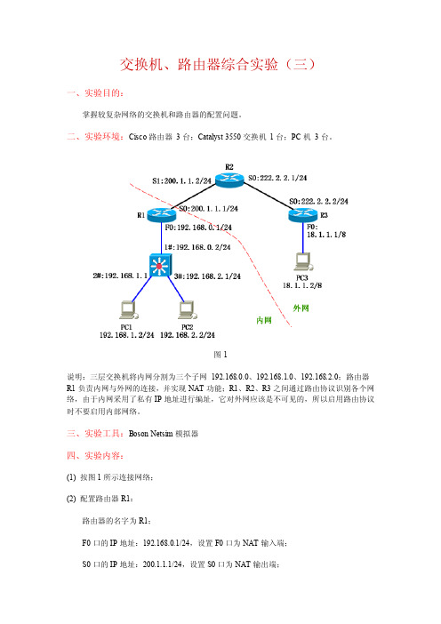
二、实验环境:Cisco路由器3台;Catalyst 3550交换机1台;PC机3台。
图1说明:三层交换机将内网分割为三个子网192.168.0.0、192.168.1.0、192.168.2.0;路由器R1负责内网与外网的连接,并实现NAT功能;R1、R2、R3之间通过路由协议识别各个网络,由于内网采用了私有IP地址进行编址,它对外网应该是不可见的,所以启用路由协议时不要启用内部网络。
三、实验工具:Boson Netsim模拟器四、实验内容:(1) 按图1所示连接网络;(2) 配置路由器R1:路由器的名字为R1;F0口的IP地址:192.168.0.1/24,设置F0口为NAT输入端;S0口的IP地址:200.1.1.1/24,设置S0口为NAT输出端;配置NAT池,地址范围为200.1.1.10~200.1.1.20,将内网中格式为192.168.*.* 的IP 地址转换为NAT池中的IP地址;配置静态路由,将目的网络为192.168.1.0 或192.168.2.0 的数据报发往192.168.0.2;配置OSPF路由协议,区域号为10,在它的外网地址上启用协议。
(3) 配置路由器R2:路由器的名字为R2;S0口的IP地址:222.2.2.1/24;S1口的IP地址:200.1.1.2/24;配置OSPF路由协议,区域号为10,在它的所有直连网络上启用协议。
(4) 配置路由器R3:路由器的名字为R3;F0口的IP地址:18.1.1.1/8;S0口的IP地址:222.2.2.2/24;配置OSPF路由协议,区域号为10,在它的所有直连网络上启用协议。
(5) 配置三层交换机:把F0/1口设置为三层路由口,IP地址为192.168.0.2/24;把F0/2口设置为三层路由口,IP地址为192.168.1.1/24;把F0/3口设置为三层路由口,IP地址为192.168.2.1/24;配置默认路由,方向为R1路由器的F0口;启用路由功能。
三层交换机路由功能配置实验总结
三层交换机路由功能配置实验总结三层交换机作为一种网络交换设备,除了基本的交换功能外,还具备了路由功能。
在网络中,路由功能是至关重要的,因为它可以实现不同子网之间的通信。
本文将介绍如何通过三层交换机实现路由功能,并进行实验总结。
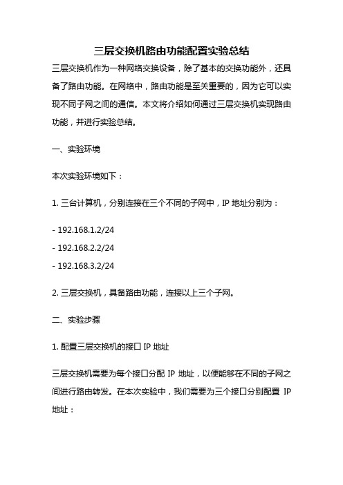
一、实验环境本次实验环境如下:1. 三台计算机,分别连接在三个不同的子网中,IP地址分别为:- 192.168.1.2/24- 192.168.2.2/24- 192.168.3.2/242. 三层交换机,具备路由功能,连接以上三个子网。
二、实验步骤1. 配置三层交换机的接口IP地址三层交换机需要为每个接口分配IP地址,以便能够在不同的子网之间进行路由转发。
在本次实验中,我们需要为三个接口分别配置IP 地址:- 接口 VLAN 1:192.168.1.1/24- 接口 VLAN 2:192.168.2.1/24- 接口 VLAN 3:192.168.3.1/24可以通过以下命令进行配置:```interface vlan 1ip address 192.168.1.1 255.255.255.0no shutdowninterface vlan 2ip address 192.168.2.1 255.255.255.0no shutdowninterface vlan 3ip address 192.168.3.1 255.255.255.0no shutdown```2. 配置路由为了实现不同子网之间的通信,需要在三层交换机中配置路由。
在本次实验中,我们需要将两个子网之间的路由添加到路由表中。
假设需要从192.168.1.0/24子网中的计算机访问192.168.3.0/24子网中的计算机,需要将192.168.3.0/24子网的路由添加到路由表中。
可以通过以下命令进行配置:```ip route 192.168.3.0 255.255.255.0 192.168.2.2```其中,192.168.3.0 255.255.255.0表示需要访问的目标子网,192.168.2.2表示下一跳路由器的IP地址。
实验五 三层交换机与路由器间路由的配置
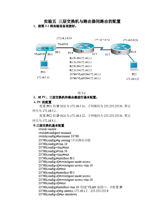
实验五 三层交换机与路由器间路由的配置1.按图5-1将实验设备连接好。
图5-12.对PC ,三层交换机和路由器进行基本配置。
A. PC 机配置配置PC1的IP 地址为172.16.5.11,子网掩码为255.255.255.0,默认网关为172.16.5.1。
配置PC2的IP 地址为172.16.3.22,子网掩码为255.255.255.0,默认网关为172.16.3.1。
B.三层交换机基本配置switch>enableswitch#configure terminalswitch(config)#hostname S3760S3760(config)#ip routing !开启路由功能S3760(config)#vlan 10S3760(config-vlan)#exitS3760(config)#vlan 50S3760(config-vlan)#exitS3760(config)#interface f0/1S3760(config-if)#switchport mode accessS3760(config-if)#switchport access vlan 10S3760(config-if)#exitS3760(config)#interface f0/5S3760(config-if)#switchport mode accessS3760(config-if)#switchport access vlan 50S3760(config-if)#exitS3760(config)#interface vlan 10 !创建VLAN 虚接口,并配置IP S3760(config-if)#ip address 172.16.1.2 255.255.255.0S3760(config-if)#no shutdownR2 S3760F1/0 S1/2 S1/2 PC2 172.16.3.22VLAN50 F1/0 F0/1 PC1172.16.5.11 R1 F1/0=172.16.1.1 R1 S1/2=172.16.2.1 R2 F1/0=172.16.3.1 R2 S1/2=172.16.2.2 S3760 VLAN10=172.16.1.2S3760 VLAN50=172.16.5.1F0/5S3760(config-if)#exitS3760(config)#interface vlan 50 !创建VLAN虚接口,并配置IPS3760(config-if)#ip address 172.16.5.1 255.255.255.0S3760(config-if)#no shutdownS3760(config-if)#endS3760#show vlanC.路由器基本配置Router1(config)#interface fastethernet 1/0Router1(config-if)#ip address 172.16.1.1 255.255.255.0Router1(config-if)#no shutdownRouter1(config-if)#exitRouter1(config)#interface serial 1/2Router1(config-if)#ip address 172.16.2.1 255.255.255.0Router1(config-if)#clock rate 64000Router1(config-if)#no shutdownRouter1(config-if)#endRouter1#show ip interface briefRouter2(config)#interface fastethernet 1/0Router2(config-if)#ip address 172.16.3.1 255.255.255.0Router2(config-if)#no shutdownRouter2(config-if)#exitRouter2(config)#interface serial 1/2Router2(config-if)#ip address 172.16.2.2 255.255.255.0Router2(config-if)#no shutdownRouter2(config-if)#endRouter2#show ip interface brief3.配置RIP V2路由协议。
实验三三层交换机设置

实验三三层交换机设置一、实验目的配置三层交换机的三层功能,实现路由作用。
二、实验设备三层交换机(1台)、主机(2台)、直连线(2条)三、实验原理三层交换机是在二层交换的基础上实现了三层的路由功能。
三层交换机基于“一次路由,多次交换”的特性,在局域网环境中转发性能远远高于路由器。
而且三层交换机同时具备二层的功能,能够和二层的交换机进行很好的数据转发。
三层交换机的以太网接口要比一般的路由器多很多,更加适合多个局域网段之间的互联。
三层交换机的所有端口在默认情况下都属于二层端口,不具备路由功能。
不能给物理端口直接配置IP地址。
但可以开启物理端口的三层路由功能。
三层交换机默认开启了路由功能,可利用ip routing命令进行控制。
四、实验内容本实验完成的是开启三层交换机物理端口的路由功能,使其完成不同网段数据的转发。
按图3所示连接设备,三层交换机采用锐捷S3550,PCA与PCB分别连接到三层交换机两端口(F0/5,F0/15)上,连接线为直连双绞线。
两台PC分别配置IP地址与子网掩码,使其不属于同一网段。
用PING命令测试二者的连通性。
开启三层交换机及其端口的三层功能,为接口F0/5、F0/15配置IP地址与掩码,使F0/5与PCA属同一网段,F0/15与PCB属同一网段。
配置PCA网关地址为F0/5地址,配置PCB网关地址为F0/15地址。
再测试各计算机的连通性。
图3 三层交换机实验拓扑五、实验步骤步骤1:连线并配置PCA 、PCB 的IP 地址,如图3所示。
步骤2:测试PCA 、PCB 连通性,并分析原因。
步骤3:开启三层交换机的路由功能。
switch#configure terminalswitch(config)#hostname s3550!为交换机更改名称 s3550(config)#ip routing !开启三层交换机的路由功能 步骤4:配置三层交换机端口的路由功能。
s3550(config)#interface fastethernet 0/5s3550(config-if)#no switchport !开启交换机端口路由功能s3550(config-if)#ip address 192.168.5.1 255.255.255.0!为交换机端口配置IP 地址 s3550(config-if)#no shutdowns3550(config-if)#end同样方法,为F0/15做相应配置。
三层交换机实现VLAN间路由实验(1)解析
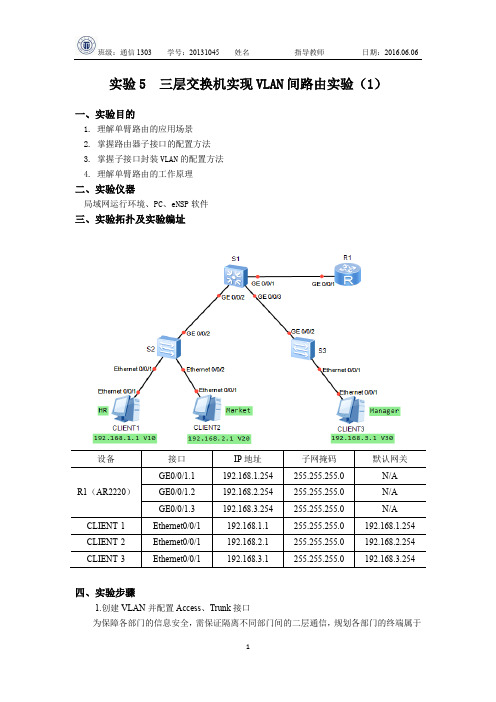
实验5 三层交换机实现VLAN间路由实验(1)一、实验目的1. 理解单臂路由的应用场景2. 掌握路由器子接口的配置方法3. 掌握子接口封装VLAN的配置方法4. 理解单臂路由的工作原理二、实验仪器局域网运行环境、PC、eNSP软件三、实验拓扑及实验编址四、实验步骤1.创建VLAN并配置Access、Trunk接口为保障各部门的信息安全,需保证隔离不同部门间的二层通信,规划各部门的终端属于不同的VLAN ,并为PC 配置相应的IP 地址。
在S2上创建VLAN10和VLAN20,把连接CLIENT -1的E0/0/1和连接CLIENT -2的E0/0/2接口配置为Access 类型接口,并分别划分到相应的VLAN 中。
截图操作结果:在S3上创建VLAN30,把连接CLIENT -3的E0/0/1接口配置为Access 类型接口,并划分到VLAN30。
截图操作结果:交换机之间或交换机和路由器之间连接的接口需要传递多个VLAN 信息,需要配置成Trunk 接口。
将S2和S3的GE0/0/2接口配置成Trunk 类型接口,并允许所有VLAN 通过。
截图操作结果:在S1上创建VLAN10、VLAN20和VLAN30,并配置交换机和路由器相连的接口为Trunk ,允许所有VLAN 通过。
截图操作结果:2.配置路由器子接口和IP 地址由于路由器R1只有一个实际的物理接口与交换机S1相连,可以在路由器上配置不同的逻辑子接口来作为不同VLAN 的网关,从而达到节省路由器接口的目的。
在R1上创建子接口GE0/0/1.1,配置IP 地址192.168.1.254/24,作为人事部网关地址。
(子接口一般配置在路由器上, 当一个物理接口需要配置多个IP 网段时,使用。
)命令行格式:[R1]interface GigabitEthernet0/0/1.1[R1-GigabitEthernet0/0/1.1]ip address 192.168.1.254 24S2 S3S1在R1上创建子接口GE0/0/1.2,配置IP地址192.168.2.254/24,作为市场部网关地址。
实验十一 用三层交换机实验VLAN间的路由
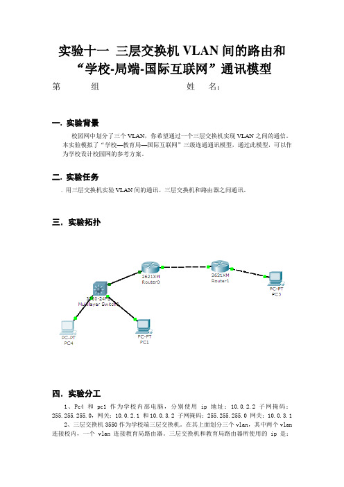
实验十一三层交换机VLAN间的路由和“学校-局端-国际互联网”通讯模型第组姓名:一.实验背景校园网中划分了三个VLAN,你希望通过一个三层交换机实现VLAN之间的通信。
本实验模拟了“学校—教育局—国际互联网”三级连通通讯模型,通过此模型,可以作为学校设计校园网的参考方案。
二. 实验任务. 用三层交换机实验VLAN间的通讯。
三层交换机和路由器之间通讯。
三.实验拓扑四.实验分工1、Pc4和pc1 作为学校内部电脑,分别使用ip地址:10.0.2.2 子网掩码:255.255.255.0,网关:10.0.2.1 和10.0.3.2 子网掩码:255.255.255.0 网关:10.0.3.12、三层交换机3550作为学校端三层交换机。
在其上面划分三个vlan,其中两个vlan 连接校内,一个vlan 连接教育局路由器。
三层交换机和教育局路由器所使用的ip是:172.16.0.1/172.16.0.2 255.255.255.252 。
创建默认路由,指向教育局路由器;3、路由器r0 模拟教育局端路由器,负责连通学校三层交换机和电信局的路由器;4、路由器r1模拟电信局端的路由器,负责互联网上的信息和教育局ip进行通信。
5、pc3作为互联网上的一台服务器,它的ip地址是:222.16.168.180 子网掩码: 255.255.255.192 网关:222.16.168.129五.实验步骤1.对S3550交换机作如下配置:Switch(config)#vlan 2 创建vlan 2Switch(config-vlan)#exitSwitch(config)#int vlan 2Switch(config-if)#ip address 10.0.2.1 255.255.255.0 给vlan2一个IP地址Switch(config-if)#no sh 激活Switch(config-if)#exitSwitch(config)#vlan 3创建Vlan 3Switch(config-vlan)#exitSwitch(config)#int vlan 3Switch(config-if)#ip address 10.0.3.1 255.255.255.0 给vlan3配一个IP地址Switch(config-if)#no sh 激活Switch(config)#int vlan 1 vlan 1 是默认vlan,不用创建Switch(config-if)#ip address 172.16.0.2 255.255.255.252 给vlan1配一个IP地址Switch(config-if)#no sh 激活Switch(config)#int fa0/2 进入交换机2 号端口Switch(config-if)#switchport access vlan 2 将2 号端口归到vlan2Switch(config-if)#exitSwitch(config)#int fa0/3 进入交换机3 号端口Switch(config-if)#switchport access vlan 3 将3 号端口归到vlan3Switch(config-if)#exit#因为默认状态下,交换机所有端口都归vlan1,所以没必要再人工将fa0/1号端口归入vlan1Switch(config)#ip route 0.0.0.0 0.0.0.0 172.16.0.1 255.255.255.252#给三层交换机设置的默认路由,将所有不明路径的数据包都扔给172.16.0.1(教育局端路由器接口)处理。
三层交换机与路由器的配置 实例(图解)

三层交换机与路由器的配置实例(图解)本文档旨在提供关于如何配置三层交换机与路由器的详细指南,并附有具体实例和图解。
下面将按照章节细化介绍。
1.交换机与路由器的基本概念及作用
1.1 交换机的作用与工作原理
1.2 路由器的作用与工作原理
2.三层交换机与路由器的区别与联系
2.1 三层交换机的特点和应用场景
2.2 路由器的特点和应用场景
3.三层交换机与路由器的配置前准备
3.1 设备检查与准备
3.2 网络规划与拓扑设计
4.三层交换机的配置步骤
4.1 连接与登录交换机
4.2 设置管理IP地质
4.3 配置VLAN
4.4 配置三层交换机的IP路由功能
5.路由器的配置步骤
5.1 连接与登录路由器
5.2 设置管理IP地质
5.3 配置静态路由
5.4 配置动态路由协议
6.三层交换机与路由器的互通配置
6.1 网络互通的基本原理
6.2 配置路由器与交换机之间的互联
6.3 配置路由器与其他网络设备的互联
7.实际案例分析与图解
7.1 案例一:简单局域网互通配置
7.2 案例二:跨网段通信配置
7.3 案例三:路由器的互联配置
附件:
本文档不涉及附件内容。
法律名词及注释:
1.三层交换机:三层交换机(Layer 3 Switch)是一种将交换机和路由器两者功能集成在一起的网络设备。
它具备交换机的高速交换与路由器的一些路由功能。
2.路由器:路由器(Router)是用于将数据包在互联网络中转发的网络设备。
它根据目的地IP地质来决定下一跳的路径,实现网络间的通信。
最新三层交换实验实验报告
最新三层交换实验实验报告实验目的:1. 熟悉三层交换机的基本配置和操作。
2. 掌握VLAN间的路由配置方法。
3. 学习并实现三层交换机的静态路由和动态路由协议配置。
实验环境:1. 三层交换机设备。
2. 多台计算机或网络设备,用于模拟不同VLAN。
3. 网络连接线缆。
4. 网络管理软件,如CLI或Web管理界面。
实验步骤:1. 连接网络设备,并确保所有设备均正确接入三层交换机。
2. 配置交换机的基本设置,包括主机名、管理VLAN等。
3. 创建VLAN,并为每个VLAN分配相应的端口。
4. 在三层交换机上配置IP地址,为不同VLAN提供Layer 3交换功能。
5. 配置VLAN间的路由,可以手动添加静态路由或启用动态路由协议(如RIP、OSPF)。
6. 测试VLAN间的通信,确保路由配置正确无误。
7. 监控网络性能和交换机状态,记录实验数据。
实验结果:1. 成功创建了VLAN,并为每个VLAN分配了正确的端口。
2. 三层交换机的IP地址配置完成,能够进行Layer 3交换。
3. 静态路由和动态路由协议均配置成功,VLAN间通信顺畅。
4. 网络测试显示,数据包能够在不同VLAN间正确传输,无丢包现象。
5. 网络性能稳定,交换机运行状态良好。
实验结论:通过本次实验,我们了解了三层交换机的工作原理和配置方法。
通过实际操作,我们掌握了VLAN间的路由配置,包括静态路由和动态路由协议的设置。
实验结果表明,三层交换机能够有效地实现不同VLAN间的通信,提高了网络的灵活性和扩展性。
此外,实验过程中对网络性能的监控也证实了三层交换机的稳定性和可靠性。
利用三层交换机实现vlan间路由实验报告

利用三层交换机实现vlan间路由实验报告实验目的:本实验旨在通过利用三层交换机实现vlan间路由,掌握vlan间路由的基本原理和配置方法。
实验设备:1. 三层交换机 x12. 计算机 x33. 网线 x4实验步骤:1. 首先,将三台计算机分别连接到三层交换机上,并将它们的IP地址设置为同一网段下的不同地址。
例如,计算机1的IP地址为192.168.1.10,计算机2的IP地址为192.168.1.20,计算机3的IP 地址为192.168.1.30。
2. 接下来,我们需要创建两个vlan。
假设我们要创建vlan10和vlan20。
3. 在三层交换机上进入全局配置模式,并输入以下命令:Switch(config)# vlan 10Switch(config-vlan)# name vlan10Switch(config-vlan)# exitSwitch(config)# vlan 20Switch(config-vlan)# name vlan20Switch(config-vlan)# exit这些命令将创建两个vlan,并为它们分配名称。
4. 然后,我们需要将端口划分到相应的vlan中。
假设我们将端口1-4划分给vlan10,端口5-8划分给vlan20。
在三层交换机上进入全局配置模式,并输入以下命令:Switch(config)# interface range fastEthernet 0/1 - 4Switch(config-if-range)# switchport mode accessSwitch(config-if-range)# switchport access vlan 10Switch(config-if-range)# exitSwitch(config)# interface range fastEthernet 0/5 - 8Switch(config-if-range)# switchport mode accessSwitch(config-if-range)# switchport access vlan 20这些命令将端口1-4划分给vlan10,端口5-8划分给vlan20。
三网元实验报告

三网元实验报告1. 实验目的本实验旨在通过搭建三网元实验环境,学习和理解计算机网络的三层架构。
通过实验,我们将会了解到三网元在计算机网络中的重要性以及其在网络通信中的角色和功能。
2. 实验环境在本实验中,我们使用以下设备搭建了实验环境:- 三台计算机,分别为C1、C2和C3。
- 三个网络交换机,分别为S1、S2和S3。
- 一台路由器,用于连接三个网络。
3. 实验步骤3.1 配置网络首先,我们需要配置每个计算机的IP地址,将它们分别连接到交换机上。
在实验环境中,我们将给C1、C2和C3分配IP地址为192.168.1.1、192.168.2.1和192.168.3.1。
接下来,我们将配置路由器,将三个交换机连接起来。
我们使用路由器的端口1连接S1,端口2连接S2,端口3连接S3。
并设置路由器和交换机之间的静态路由。
3.2 配置三网元为了实现三网元的功能,我们需要对每个交换机进行配置。
3.2.1 配置S1首先,我们需要在S1上配置VLAN。
假设我们将C1接口连接到VLAN1,C2接口连接到VLAN2,C3接口连接到VLAN3。
其次,我们配置S1的VLAN接口。
具体来说,我们将VLAN1端口配置为静态访问模式,VLAN2端口配置为动态访问模式,VLAN3端口禁用。
最后,我们启用S1的三层交换功能,并配置路由表,将流量从VLAN1转发到VLAN2和VLAN3。
3.2.2 配置S2和S3类似地,我们也需要在S2和S3上进行类似的配置。
根据实验需求,我们配置S2上的VLAN和端口,以及启用三层交换功能。
然后在S3上进行相同的配置。
3.3 测试网络通信完成上述配置后,我们可以测试网络的通信功能。
我们将通过ping命令测试C1、C2和C3之间的互联是否正常。
如果网络配置正确,我们应该能够在每个计算机上成功ping通其他两台计算机。
3.4 分析实验结果通过测试,我们可以得出以下结论:- 三层交换机可以根据数据包的IP地址进行路由转发,实现网络的互联。
实验三、三层交换+路由实验之 上联口使用access口
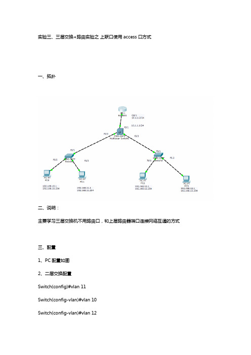
实验三、三层交换+路由实验之上联口使用access口方式一、拓扑二、说明:主要学习三层交换机不用路由口,和上层路由器端口连接网络互通的方式三、配置1、PC配置如图2、二层交换配置Switch(config)#vlan 11Switch(config-vlan)#vlan 10Switch(config-vlan)#vlan 12Switch(config-vlan)#vlan 13Switch(config-vlan)#vlan 14右边sw相同,略3、三层交换配置Switch(config)#vlan 10Switch(config-vlan)#vlan 11Switch(config-vlan)#vlan 12Switch(config-vlan)#vlan 13Switch(config-vlan)#vlan 14//新建vlanSwitch(config)#int vlan10Switch(config-if)#ip address 192.168.10.254 255.255.255.0 Switch(config-if)#int vlan11Switch(config-if)#ip address 192.168.11.254 255.255.255.0 Switch(config-if)#int vlan12Switch(config-if)#ip address 192.168.12.254 255.255.255.0 Switch(config-if)#int vlan13Switch(config-if)#ip address 192.168.13.254 255.255.255.0 Switch(config-if)#int vlan14Switch(config-if)#ip address 10.1.1.1 255.255.255.0//vlan接口地址,注意,vlan14接口为上层和路由器接口通信地址Switch(config-if)#int f0/2Switch(config-if)#switchport trunk encapsulation dot1qSwitch(config-if)#switchport mode trunkSwitch(config-if)#int f0/3Switch(config-if)#switchport trunk encapsulation dot1qSwitch(config-if)#switchport mode trunk//连接交换机端口设置为trunk,注意封装格式。
- 1、下载文档前请自行甄别文档内容的完整性,平台不提供额外的编辑、内容补充、找答案等附加服务。
- 2、"仅部分预览"的文档,不可在线预览部分如存在完整性等问题,可反馈申请退款(可完整预览的文档不适用该条件!)。
- 3、如文档侵犯您的权益,请联系客服反馈,我们会尽快为您处理(人工客服工作时间:9:00-18:30)。
三层交换机及路由器子网互联实验运行环境: GNS3实验目的: 在三层交换机及路由器间运行动态路由协议, 实现各子网互通拓扑图如下:交换机S3550配置:S3550>S3550>enableS3550#conf tEnter configuration commands, one per line. End with CNTL/Z.S3550(config)#vlan 10^% Invalid input detected at '^' marker.S3550(config)#exitS3550#*Mar 1 00:05:11.791: %SYS-5-CONFIG_I: Configured from console by console S3550#vlan databaseS3550(vlan)#vlan 10VLAN 10 added:Name: VLAN0010S3550(vlan)#vlan 20VLAN 20 added:Name: VLAN0020S3550(vlan)#no vlan 20Deleting VLAN 20...S3550(vlan)#vlan 50VLAN 50 added:Name: VLAN0050S3550(vlan)#exitAPPLY completed.Exiting....S3550#conf tEnter configuration commands, one per line. End with CNTL/Z.S3550(config)#int f0/1S3550(config-if)#swS3550(config-if)#switchport mode accessS3550(config-if)#swS3550(config-if)#switchport access vlan 10S3550(config-if)#no shutS3550(config-if)#exitS3550(config)#*Mar 1 00:06:52.035: %LINK-3-UPDOWN: Interface FastEthernet0/1, changed state to up*Mar 1 00:06:53.035: %LINEPROTO-5-UPDOWN: Line protocol on Interface FastEthernet0/1, changed state to upS3550(config)#int f0/5S3550(config-if)#swS3550(config-if)#switchport mode accessS3550(config-if)#swS3550(config-if)#switchport access vlan 50S3550(config-if)#no shutS3550(config-if)#S3550(config-if)#e*Mar 1 00:07:27.195: %LINK-3-UPDOWN: Interface FastEthernet0/5, changed state to up*Mar 1 00:07:28.195: %LINEPROTO-5-UPDOWN: Line protocol on Interface FastEthernet0/5, changed state to upS3550(config-if)#exitS3550(config)#int vlan 10S3550(config-if)#ip add 1*Mar 1 00:07:46.083: %LINEPROTO-5-UPDOWN: Line protocol on Interface Vlan10, changed state to upS3550(config-if)#ip add 172.16.1.2 255.255.255.0S3550(config-if)#no shutS3550(config-if)#exitS3550(config)#int vlan 50S3550(config-if)#ip add 17*Mar 1 00:08:19.507: %LINEPROTO-5-UPDOWN: Line protocol on Interface Vlan50, changed state to upS3550(config-if)#ip add 172.16.5.1 255.255.255.0S3550(config-if)#no shutS3550(config-if)#exitS3550(config)#验证:S3550#sh vlan-switchVLAN Name Status Ports---- -------------------------------- --------- -------------------------------1 default active Fa0/0, Fa0/2, Fa0/3, Fa0/4Fa0/6, Fa0/7, Fa0/8, Fa0/9Fa0/10, Fa0/11, Fa0/12, Fa0/13Fa0/14, Fa0/1510 VLAN0010 active Fa0/150 VLAN0050 active Fa0/51002 fddi-default active1003 token-ring-default active1004 fddinet-default active1005 trnet-default activeVLAN Type SAID MTU Parent RingNo BridgeNo Stp BrdgMode Trans1 Trans2 ---- ----- ---------- ----- ------ ------ -------- ---- -------- ------ ------1 enet 100001 1500 - - - - - 1002 1003 10 enet 100010 1500 - - - - - 0 050 enet 100050 1500 - - - - - 0 0 1002 fddi 101002 1500 - - - - - 1 1003 1003 tr 101003 1500 1005 0 - - srb 1 1002 1004 fdnet 101004 1500 - - 1 ibm - 0 0 1005 trnet 101005 1500 - - 1 ibm - 0 0S3550#sh ip intFastEthernet0/0 is administratively down, line protocol is downInternet protocol processing disabledFastEthernet0/1 is up, line protocol is upInternet protocol processing disabledFastEthernet0/2 is administratively down, line protocol is downInternet protocol processing disabledFastEthernet0/3 is administratively down, line protocol is downInternet protocol processing disabledFastEthernet0/4 is administratively down, line protocol is downInternet protocol processing disabledFastEthernet0/5 is up, line protocol is upInternet protocol processing disabledFastEthernet0/6 is administratively down, line protocol is downInternet protocol processing disabledFastEthernet0/7 is administratively down, line protocol is downInternet protocol processing disabledFastEthernet0/8 is administratively down, line protocol is down Internet protocol processing disabledFastEthernet0/9 is administratively down, line protocol is down Internet protocol processing disabledFastEthernet0/10 is administratively down, line protocol is down Internet protocol processing disabledFastEthernet0/11 is administratively down, line protocol is down Internet protocol processing disabledFastEthernet0/12 is administratively down, line protocol is down Internet protocol processing disabledFastEthernet0/13 is administratively down, line protocol is down Internet protocol processing disabledFastEthernet0/14 is administratively down, line protocol is down Internet protocol processing disabledFastEthernet0/15 is administratively down, line protocol is down Internet protocol processing disabledVlan1 is administratively down, line protocol is downInternet protocol processing disabledVlan10 is up, line protocol is upInternet address is 172.16.1.2/24Broadcast address is 255.255.255.255Address determined by setup commandMTU is 1500 bytesHelper address is not setDirected broadcast forwarding is disabledOutgoing access list is not setInbound access list is not setProxy ARP is enabledLocal Proxy ARP is disabledSecurity level is defaultSplit horizon is enabledICMP redirects are always sentICMP unreachables are always sentICMP mask replies are never sentIP fast switching is enabledIP fast switching on the same interface is disabledIP Flow switching is disabledIP CEF switching is enabledIP CEF Fast switching turbo vectorIP multicast fast switching is enabledIP multicast distributed fast switching is disabledIP route-cache flags are Fast, CEFRouter Discovery is disabledIP output packet accounting is disabledIP access violation accounting is disabledTCP/IP header compression is disabledRTP/IP header compression is disabledPolicy routing is disabledNetwork address translation is disabledWCCP Redirect outbound is disabledWCCP Redirect inbound is disabledWCCP Redirect exclude is disabledBGP Policy Mapping is disabledVlan50 is up, line protocol is upInternet address is 172.16.5.1/24Broadcast address is 255.255.255.255Address determined by setup commandMTU is 1500 bytesHelper address is not setDirected broadcast forwarding is disabled Outgoing access list is not setInbound access list is not setProxy ARP is enabledLocal Proxy ARP is disabledSecurity level is defaultSplit horizon is enabledICMP redirects are always sentICMP unreachables are always sentICMP mask replies are never sentIP fast switching is enabledIP fast switching on the same interface is disabled IP Flow switching is disabledIP CEF switching is enabledIP CEF Fast switching turbo vectorIP multicast fast switching is enabledIP multicast distributed fast switching is disabled IP route-cache flags are Fast, CEFRouter Discovery is disabledIP output packet accounting is disabledIP access violation accounting is disabledTCP/IP header compression is disabledRTP/IP header compression is disabledPolicy routing is disabledNetwork address translation is disabledWCCP Redirect outbound is disabledWCCP Redirect inbound is disabledWCCP Redirect exclude is disabledBGP Policy Mapping is disabledS3550#路由器Router01配置:Router01>enableRouter01#conf tEnter configuration commands, one per line. End with CNTL/Z.Router01(config)#int f0/1Router01(config-if)#ip add 172.16.1.1 255.255.255.0Router01(config-if)#no shutRouter01(config-if)#exi*Jul 6 13:02:26.719: %LINK-3-UPDOWN: Interface FastEthernet0/1, changed state to up Router01(config-if)#exitRouter01(config)#*Jul 6 13:02:26.719: %ENTITY_ALARM-6-INFO: CLEAR INFO Fa0/1 Physical Port Administrative State Down*Jul 6 13:02:27.791: %LINEPROTO-5-UPDOWN: Line protocol on Interface FastEthernet0/1, changed state to upRouter01(config)#int s1/2Router01(config-if)#ip add 172.16.2.1 255.255.255.0Router01(config-if)#clock rate 64000Router01(config-if)#no shutRouter01(config-if)#*Jul 6 13:03:17.451: %LINK-3-UPDOWN: Interface Serial1/2, changed state to upRouter01(config-if)#*Jul 6 13:03:17.451: %ENTITY_ALARM-6-INFO: CLEAR INFO Se1/2 Physical Port Administrative State DownRouter01(config-if)#*Jul 6 13:03:18.455: %LINEPROTO-5-UPDOWN: Line protocol on Interface Serial1/2, changed state to upRouter01(config-if)#exitRouter01(config)#exitRouter01#*Jul 6 13:03:40.223: %SYS-5-CONFIG_I: Configured from console by consoleRouter01#*Jul 6 13:03:43.807: %LINEPROTO-5-UPDOWN: Line protocol on Interface Serial1/2, changed state to downRouter01#验证:Router01#show ip int briefInterface IP-Address OK? Method Status Protocol FastEthernet0/0 unassigned YES unset administratively down down FastEthernet0/1 172.16.1.1 YES manual up up Serial1/0 unassigned YES unset administratively down down Serial1/1 unassigned YES unset administratively down down Serial1/2 172.16.2.1 YES manual up down Serial1/3 unassigned YES unset administratively down down Router01#路由器Router02配置:Router02>enableRouter02#conf tEnter configuration commands, one per line. End with CNTL/Z.Router02(config)#int s1/2Router02(config-if)#ip add 172.16.2.2 255.255.255.0Router02(config-if)#no shutRouter02(config-if)#*Jul 6 13:06:32.975: %LINK-3-UPDOWN: Interface Serial1/2, changed state to upRouter02(config-if)#in*Jul 6 13:06:32.975: %ENTITY_ALARM-6-INFO: CLEAR INFO Se1/2 Physical Port Administrative State Down*Jul 6 13:06:33.979: %LINEPROTO-5-UPDOWN: Line protocol on Interface Serial1/2, changed state to upRouter02(config-if)#int f0/1Router02(config-if)#ip add 172.16.3.1 255.255.255.0Router02(config-if)#no shutRouter02(config-if)#en*Jul 6 13:06:59.519: %LINK-3-UPDOWN: Interface FastEthernet0/1, changed state to up Router02(config-if)#en*Jul 6 13:06:59.519: %ENTITY_ALARM-6-INFO: CLEAR INFO Fa0/1 Physical Port Administrative State DownRouter02(config-if)#en% Ambiguous command: "en"Router02(config)#*Jul 6 13:07:00.519: %LINEPROTO-5-UPDOWN: Line protocol on Interface FastEthernet0/1, changed state to upRouter02(config)#endRouter02#*Jul 6 13:07:05.815: %SYS-5-CONFIG_I: Configured from console by consoleRouter02#配置验证:Router02#sh ip interface briefInterface IP-Address OK? Method Status Protocol FastEthernet0/0 unassigned YES unset administratively down down FastEthernet0/1 172.16.3.1 YES manual up up Serial1/0 unassigned YES unset administratively down down Serial1/1 unassigned YES unset administratively down down Serial1/2 172.16.2.2 YES manual up up Serial1/3 unassigned YES unset administratively down down Router02#交换机路由配置:S3550#conf tEnter configuration commands, one per line. End with CNTL/Z.S3550(config)#router ripS3550(config-router)#version 2S3550(config-router)#network 172.16.1.0S3550(config-router)#network 172.16.5.0S3550(config-router)#endS3550#*Mar 1 00:25:08.635: %SYS-5-CONFIG_I: Configured from console by consoleS3550#show ip routeCodes: C - connected, S - static, R - RIP, M - mobile, B - BGPD - EIGRP, EX - EIGRP external, O - OSPF, IA - OSPF inter areaN1 - OSPF NSSA external type 1, N2 - OSPF NSSA external type 2E1 - OSPF external type 1, E2 - OSPF external type 2i - IS-IS, su - IS-IS summary, L1 - IS-IS level-1, L2 - IS-IS level-2ia - IS-IS inter area, * - candidate default, U - per-user static routeo - ODR, P - periodic downloaded static routeGateway of last resort is not set172.16.0.0/24 is subnetted, 4 subnetsC 172.16.5.0 is directly connected, Vlan50C 172.16.1.0 is directly connected, Vlan10R 172.16.2.0 [120/1] via 172.16.1.1, 00:00:03, Vlan10R 172.16.3.0 [120/2] via 172.16.1.1, 00:00:03, Vlan10S3550#路由器Router01的路由配置:Router01#conf tEnter configuration commands, one per line. End with CNTL/Z.Router01(config)#router ripRouter01(config-router)#network 172.16.1.0Router01(config-router)#network 172.16.2.0Router01(config-router)#version 2Router01(config-router)#no auto-sRouter01(config-router)#no auto-summaryRouter01(config-router)#endRouter01#show*Jul 6 13:11:17.611: %SYS-5-CONFIG_I: Configured from console by console Router01#show ip routeCodes: C - connected, S - static, R - RIP, M - mobile, B - BGPD - EIGRP, EX - EIGRP external, O - OSPF, IA - OSPF inter areaN1 - OSPF NSSA external type 1, N2 - OSPF NSSA external type 2E1 - OSPF external type 1, E2 - OSPF external type 2i - IS-IS, su - IS-IS summary, L1 - IS-IS level-1, L2 - IS-IS level-2ia - IS-IS inter area, * - candidate default, U - per-user static routeo - ODR, P - periodic downloaded static routeGateway of last resort is not set172.16.0.0/24 is subnetted, 4 subnetsR 172.16.5.0 [120/1] via 172.16.1.2, 00:00:11, FastEthernet0/1C 172.16.1.0 is directly connected, FastEthernet0/1C 172.16.2.0 is directly connected, Serial1/2R 172.16.3.0 [120/1] via 172.16.2.2, 00:00:11, Serial1/2Router01#路由器Router02的路由配置:Router02#conf tEnter configuration commands, one per line. End with CNTL/Z.Router02(config)#router ripRouter02(config-router)#versionRouter02(config)#router ripRouter02(config-router)#version 2Router02(config-router)#network 172.16.2.0Router02(config-router)#network 172.16.3.0Router02(config-router)#no auto-sRouter02(config-router)#no auto-summaryRouter02(config-router)#endRouter02#show*Jul 6 13:11:45.211: %SYS-5-CONFIG_I: Configured from console by console Router02#show ip routeCodes: C - connected, S - static, R - RIP, M - mobile, B - BGPD - EIGRP, EX - EIGRP external, O - OSPF, IA - OSPF inter areaN1 - OSPF NSSA external type 1, N2 - OSPF NSSA external type 2E1 - OSPF external type 1, E2 - OSPF external type 2i - IS-IS, su - IS-IS summary, L1 - IS-IS level-1, L2 - IS-IS level-2ia - IS-IS inter area, * - candidate default, U - per-user static routeo - ODR, P - periodic downloaded static routeGateway of last resort is not set172.16.0.0/24 is subnetted, 4 subnetsR 172.16.5.0 [120/2] via 172.16.2.1, 00:00:15, Serial1/2R 172.16.1.0 [120/1] via 172.16.2.1, 00:00:15, Serial1/2C 172.16.2.0 is directly connected, Serial1/2C 172.16.3.0 is directly connected, FastEthernet0/1Router02#客户端配置如下:路由验证:S3550交换机配置:S3550#sh runBuilding configuration...Current configuration : 1533 bytes!version 12.3service timestamps debug datetime msec service timestamps log datetime msec no service password-encryption!hostname S3550!boot-start-markerboot-end-marker!!no aaa new-modelip subnet-zero!!no ip domain lookupip cef!!!!!!!!!!!!!!!!!!!interface FastEthernet0/0 no ip address shutdown!interface FastEthernet0/1 switchport access vlan 10 no ip address!interface FastEthernet0/2 no ip address shutdown!interface FastEthernet0/3 no ip address shutdown!interface FastEthernet0/4 no ip address shutdown!interface FastEthernet0/5 switchport access vlan 50 no ip addressinterface FastEthernet0/6 no ip address shutdown!interface FastEthernet0/7 no ip address shutdown!interface FastEthernet0/8 no ip address shutdown!interface FastEthernet0/9 no ip address shutdown!interface FastEthernet0/10 no ip address shutdown!interface FastEthernet0/11 no ip address shutdown!interface FastEthernet0/12 no ip address shutdown!interface FastEthernet0/13 no ip address shutdown!interface FastEthernet0/14 no ip address shutdown!interface FastEthernet0/15 no ip address shutdown!interface Vlan1no ip address shutdowninterface Vlan10ip address 172.16.1.2 255.255.255.0 !interface Vlan50ip address 172.16.5.1 255.255.255.0 !!router ripversion 2network 172.16.0.0!no ip http serverno ip http secure-serverip classless!!!!!!!!!!!line con 0exec-timeout 0 0logging synchronousline aux 0line vty 0 4!!endS3550#路由器Router01配置信息:Router01#sh runBuilding configuration...Current configuration : 1103 bytesversion 12.4service timestamps debug datetime msec service timestamps log datetime msec no service password-encryption!hostname Router01!boot-start-markerboot-end-marker!!no aaa new-modelip cef!!!!no ip domain lookup!multilink bundle-name authenticated!!!!!!!!!!!!!!!!!!!!!interface FastEthernet0/0no ip addressshutdownduplex autospeed auto!interface FastEthernet0/1ip address 172.16.1.1 255.255.255.0 duplex autospeed auto!interface Serial1/0no ip addressshutdownserial restart-delay 0!interface Serial1/1no ip addressshutdownserial restart-delay 0!interface Serial1/2ip address 172.16.2.1 255.255.255.0 serial restart-delay 0clock rate 64000!interface Serial1/3no ip addressshutdownserial restart-delay 0!router ripversion 2network 172.16.0.0no auto-summary!no ip http serverno ip http secure-server!!!logging alarm informational!!!!!control-plane!!!!!!gatekeepershutdown!!line con 0exec-timeout 0 0logging synchronousstopbits 1line aux 0stopbits 1line vty 0 4!!endRouter01#路由器Router02配置信息如下: Router02#show runRouter02#show running-config Building configuration...Current configuration : 1085 bytes!version 12.4service timestamps debug datetime msec service timestamps log datetime msec no service password-encryption!hostname Router02!boot-start-markerboot-end-marker!!no aaa new-modelip cef!!!!no ip domain lookup!multilink bundle-name authenticated !!!!!!!!!!!!!!!!!!!!!interface FastEthernet0/0no ip addressshutdownduplex autospeed auto!interface FastEthernet0/1ip address 172.16.3.1 255.255.255.0 duplex autospeed auto!interface Serial1/0no ip addressshutdownserial restart-delay 0!interface Serial1/1no ip addressshutdownserial restart-delay 0!interface Serial1/2ip address 172.16.2.2 255.255.255.0 serial restart-delay 0!interface Serial1/3no ip addressshutdownserial restart-delay 0!router ripversion 2network 172.16.0.0no auto-summary!no ip http serverno ip http secure-server!!!logging alarm informational!!!!!control-plane!!!!!!gatekeepershutdown!!line con 0exec-timeout 0 0logging synchronousstopbits 1line aux 0stopbits 1line vty 0 4!!endRouter02#增加一个vlan100的实验拓扑图:交换机配置:S3550#vlan databaseS3550(vlan)#vlan 100VLAN 100 added:Name: VLAN0100S3550(vlan)#exitAPPLY completed.Exiting....S3550#conf tEnter configuration commands, one per line. End with CNTL/Z. S3550(config)#int f0/10S3550(config-if)#swS3550(config-if)#switchport mode accessS3550(config-if)#swS3550(config-if)#switchport access vlan 100S3550(config-if)#no shutS3550(config-if)#*Mar 1 00:49:35.647: %LINK-3-UPDOWN: Interface FastEthernet0/10, changed state to up*Mar 1 00:49:36.647: %LINEPROTO-5-UPDOWN: Line protocol on Interface FastEthernet0/10, changed state to upS3550(config-if)#exitS3550(config)#int vlan 100S3550(config-if)#ip add*Mar 1 00:49:50.019: %LINEPROTO-5-UPDOWN: Line protocol on Interface Vlan100, changed state to upS3550(config-if)#ip add 192.168.1.1 255.255.255.0S3550(config-if)#no shutS3550(config-if)#exitS3550(config)#router ripS3550(config-router)#network 192.168.1.0S3550(config-router)#version 2S3550(config-router)#endS3550#sh ip*Mar 1 00:50:47.723: %SYS-5-CONFIG_I: Configured from console by consoleS3550#sh ip routeCodes: C - connected, S - static, R - RIP, M - mobile, B - BGPD - EIGRP, EX - EIGRP external, O - OSPF, IA - OSPF inter areaN1 - OSPF NSSA external type 1, N2 - OSPF NSSA external type 2E1 - OSPF external type 1, E2 - OSPF external type 2i - IS-IS, su - IS-IS summary, L1 - IS-IS level-1, L2 - IS-IS level-2ia - IS-IS inter area, * - candidate default, U - per-user static routeo - ODR, P - periodic downloaded static routeGateway of last resort is not set172.16.0.0/24 is subnetted, 4 subnetsC 172.16.5.0 is directly connected, Vlan50C 172.16.1.0 is directly connected, Vlan10R 172.16.2.0 [120/1] via 172.16.1.1, 00:00:20, Vlan10R 172.16.3.0 [120/2] via 172.16.1.1, 00:00:20, Vlan10C 192.168.1.0/24 is directly connected, Vlan100S3550#路由器Router01路由验证:Router01#sh ip routeCodes: C - connected, S - static, R - RIP, M - mobile, B - BGPD - EIGRP, EX - EIGRP external, O - OSPF, IA - OSPF inter areaN1 - OSPF NSSA external type 1, N2 - OSPF NSSA external type 2E1 - OSPF external type 1, E2 - OSPF external type 2i - IS-IS, su - IS-IS summary, L1 - IS-IS level-1, L2 - IS-IS level-2ia - IS-IS inter area, * - candidate default, U - per-user static routeo - ODR, P - periodic downloaded static routeGateway of last resort is not set172.16.0.0/24 is subnetted, 4 subnetsR 172.16.5.0 [120/1] via 172.16.1.2, 00:00:12, FastEthernet0/1C 172.16.1.0 is directly connected, FastEthernet0/1C 172.16.2.0 is directly connected, Serial1/2R 172.16.3.0 [120/1] via 172.16.2.2, 00:00:13, Serial1/2R 192.168.1.0/24 [120/1] via 172.16.1.2, 00:00:12, FastEthernet0/1 Router01#路由器Router02路由验证:Router02#sh ip routeCodes: C - connected, S - static, R - RIP, M - mobile, B - BGPD - EIGRP, EX - EIGRP external, O - OSPF, IA - OSPF inter areaN1 - OSPF NSSA external type 1, N2 - OSPF NSSA external type 2E1 - OSPF external type 1, E2 - OSPF external type 2i - IS-IS, su - IS-IS summary, L1 - IS-IS level-1, L2 - IS-IS level-2ia - IS-IS inter area, * - candidate default, U - per-user static routeo - ODR, P - periodic downloaded static routeGateway of last resort is not set172.16.0.0/24 is subnetted, 4 subnetsR 172.16.5.0 [120/2] via 172.16.2.1, 00:00:11, Serial1/2R 172.16.1.0 [120/1] via 172.16.2.1, 00:00:11, Serial1/2C 172.16.2.0 is directly connected, Serial1/2C 172.16.3.0 is directly connected, FastEthernet0/1R 192.168.1.0/24 [120/2] via 172.16.2.1, 00:00:11, Serial1/2Router02#交换机配置信息:S3550#sh running-configBuilding configuration...Current configuration : 1630 bytes!version 12.3service timestamps debug datetime msec service timestamps log datetime msec no service password-encryption!hostname S3550!boot-start-markerboot-end-marker!!no aaa new-modelip subnet-zero!!no ip domain lookup!ip cef!!!!!!!!!!!!!!!!!!!interface FastEthernet0/0no ip addressshutdown!switchport access vlan 10 no ip address!interface FastEthernet0/2 no ip addressshutdown!interface FastEthernet0/3 no ip addressshutdown!interface FastEthernet0/4 no ip addressshutdown!interface FastEthernet0/5 switchport access vlan 50 no ip address!interface FastEthernet0/6 no ip addressshutdown!interface FastEthernet0/7 no ip addressshutdown!interface FastEthernet0/8 no ip addressshutdown!interface FastEthernet0/9 no ip addressshutdown!interface FastEthernet0/10 switchport access vlan 100 no ip address!interface FastEthernet0/11 no ip addressshutdown!no ip addressshutdown!interface FastEthernet0/13no ip addressshutdown!interface FastEthernet0/14no ip addressshutdown!interface FastEthernet0/15no ip addressshutdown!interface Vlan1no ip addressshutdown!interface Vlan10ip address 172.16.1.2 255.255.255.0 !interface Vlan50ip address 172.16.5.1 255.255.255.0 !interface Vlan100ip address 192.168.1.1 255.255.255.0 !!router ripversion 2network 172.16.0.0network 192.168.1.0!no ip http serverno ip http secure-serverip classless!!!!!!!!!!!line con 0exec-timeout 0 0 logging synchronous line aux 0line vty 0 4!!endS3550#。