pcb封装压力传感器
压力传感器原理【详解】
压力传感器原理内容来源网络,由“深圳机械展(11万㎡,1100多家展商,超10万观众)”收集整理!更多cnc加工中心、车铣磨钻床、线切割、数控刀具工具、工业机器人、非标自动化、数字化无人工厂、精密测量、3D打印、激光切割、钣金冲压折弯、精密零件加工等展示,就在深圳机械展。
一.压力传感器原理一些常用传感器原理及其应用:1、应变片压力传感器原理与应用力学传感器的种类繁多,如电阻应变片压力传感器、半导体应变片压力传感器、压阻式压力传感器、电感式压力传感器、电容式压力传感器、谐振式压力传感器及电容式加速度传感器等。
但应用最为广泛的是压阻式压力传感器,它具有极低的价格和较高的精度以及较好的线性特性。
下面我们主要介绍这类传感器。
在了解压阻式力传感器时,我们首先认识一下电阻应变片这种元件。
电阻应变片是一种将被测件上的应变变化转换成为一种电信号的敏感器件.它是压阻式应变传感器的主要组成部分之一。
电阻应变片应用最多的是金属电阻应变片和半导体应变片两种。
金属电阻应变片又有丝状应变片和金属箔状应变片两种.通常是将应变片通过特殊的粘和剂紧密的粘合在产生力学应变基体上,当基体受力发生应力变化时,电阻应变片也一起产生形变,使应变片的阻值发生改变,从而使加在电阻上的电压发生变化.这种应变片在受力时产生的阻值变化通常较小,一般这种应变片都组成应变电桥,并通过后续的仪表放大器进行放大,再传输给处理电路(通常是A/D转换和CPU)显示或执行机构。
金属电阻应变片的内部结构1、应变片压力传感器原理如图1所示,是电阻应变片的结构示意图,它由基体材料、金属应变丝或应变箔、绝缘保护片和引出线等部分组成。
根据不同的用途,电阻应变片的阻值可以由设计者设计,但电阻的取值范围应注意:阻值太小,所需的驱动电流太大,同时应变片的发热致使本身的温度过高,不同的环境中使用,使应变片的阻值变化太大,输出零点漂移明显,调零电路过于复杂。
而电阻太大,阻抗太高,抗外界的电磁干扰能力较差.一般均为几十欧至几十千欧左右。
美国GE Nova公司压力传感器

美国GE Nova公司压力传感器NPC系列双列直插结构陶瓷封装芯片GE Nova Sensor公司NPC/410/1210/1220系列,适用于低成本、大批量应用场合;其双列直插结构,方便用于印刷电路板安装;并有多种压力接口和管脚结构供用户选用择。
正如Nova Sensor公司的所有硅压力传感器一样,NPC系列应用于了Senstable压阻传感技术,硅敏感元件采用了先进的离子注入工艺,由上述工艺所形成的高质量惠斯登电桥电路和精密的力学结构,实现了机电一体化转换。
本系列可用于兼容气体介质的绝压、表压、和差压检测,具有优良的性能。
特点:■低成本,可互换性;■双列直插式(PID)结构,可用于印刷电路板(PCB)安装■可测液、气兼容介质■恒流1.5mA供电■具有绝压、表压和差压形式■压力范围:0~2.5KPa到0~700KPa■高精度:±0.1%应用:■医疗设备:血压计、呼吸机和灌注泵■空调、通风设备■气流检测■计算机外围设备■过程控制■电缆泄露检测NPI系列充油隔离芯体GE Nova Sensor 公司NPI系列,将固态集成工艺与隔离膜片技术相结合,扩散硅芯片被封装在充油腔体内,并通过不锈钢膜片和外壳将其与测量介质隔离开来,向用户提供性价比良好的产品。
标准产品提供了多种压力接口,可满足焊接密封和侧密封设计要求正如Nova Sensor 公司的所有硅压力传感器一样,NPI系列应用于了Senstable压阻传感器技术及温度补偿工艺,将温度补偿电阻环路制作在混合陶瓷基片上,在0~70℃的温度补偿范围内,提供了最小的温度误差0.75%(最大值).本系列可广泛应用于气、液压力的检测,基至在恶劣环境下,如:污水、蒸气、弱腐蚀性介质,仍俱有优良的性能。
特点:■固态、高可靠性、高灵敏度■ 316不锈钢隔离膜片,腐蚀性介质可兼容■压力范围:0~17.2KPa到0~35MPa■提供恒流和恒压供电应用:■液、气压力控制系统■自动过程检测和过程控制系统■能源管理、环保及水处理系统■船舶及航海系统■冷冻及制氧设备■柴油机系统■农机设备NPH系列TO-8封装结构芯体GE Novasensor 公司的NPH系列,将集成化的敏感芯片封装于标准的TO-8型电子外壳内,便于安装到印制线路板上,是具有良好性价比的产品。
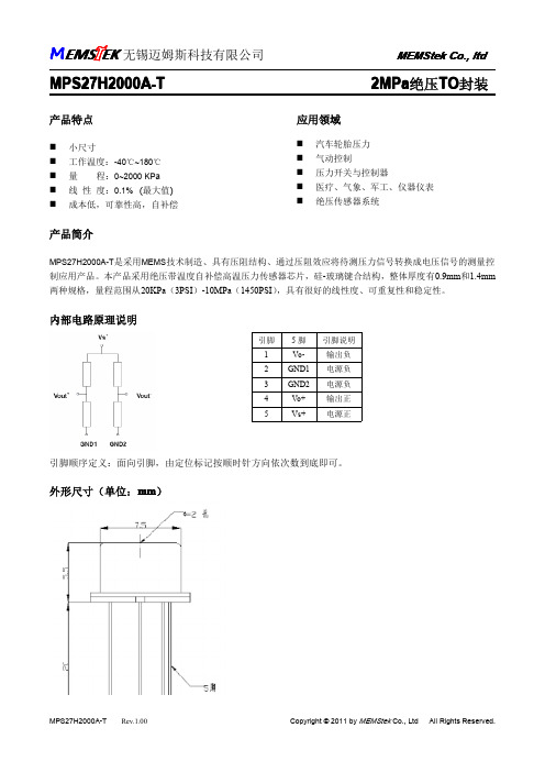
MPS27H2000A-T压力传感器产品资料
最大值 00 20 2000 180 6 +30 140 0.2 00 +5 +500 +0.15 +0.30 0.5 10 200 2X
单位 K Pa ℃ kΩ mV mV %FS ppm/℃ ‰FS/℃ ‰FS/℃ mV V ℃
工作温度 桥臂电阻 零点漂移 满量程输出 线性度* 电阻温度系数** 零位温漂** 灵敏度温漂** 零位温度迟滞 驱动电压 贮存温度 压力过载
MPS27H2000A-T Rev.1.00
联 系 人:袁志强 联系电话: 13601489320 电子邮箱: memstek@ yuandy.2008@
Copyright © 2011 by MEMStek Co., Ltd All Rights Reserved.
内部电路原理说明
引脚 1 2 3 4 5 5脚 VoGND1 GND2 Vo+ Vs+ 引脚说明 输出负 电源负 电源负 输出正 电源正
引脚顺序定义:面向引脚,由定位标记按顺位:mm)
MPS27H2000A-T
Rev.1.00
Copyright © 2011 by MEMStek Co., Ltd
2MPa绝压TO封装
应用领域
� � � � � 汽车轮胎压力 气动控制 压力开关与控制器 医疗、气象、军工、仪器仪表 绝压传感器系统
产品简介
MPS27H2000A-T是采用MEMS技术制造、具有压阻结构、通过压阻效应将待测压力信号转换成电压信号的测量控
制应用产品。本产品采用绝压带温度自补偿高温压力传感器芯片,硅-玻璃键合结构,整体厚度有0.9mm和1.4mm 两种规格,量程范围从 20KPa(3PSI)-10MPa(1450PSI) ,具有很好的线性度、可重复性和稳定性。
传感器种类及品牌
传感器种类及品牌称重传感器压力传感器流量传感器位移传感器湿度传感器液位传感器压力传感器静压式液位传感器隔离膜片压力传感器MEAS 压力传感器/变送器PC 封装式压力传感器数字压力传感器振动传感器/加速度传感器压电式加速度传感器压电薄膜振动传感器硅压阻MEMS技术+ 湿度传感器HM 系列湿度传感器/变送器HT 系列湿度传感器-PCB 模块 HS 系列温湿度传感器 + 力传感器FGP 力传感器FGP扭矩传感器F系列力传感器 /称重传感器EL 系列高性能力传感器 + 压电薄膜传感器压电薄膜加速度计压电薄膜超声波传感器压电电缆压电薄膜元件 + 油品分析传感器 + 温度传感器镍 4000 系列 Atexis 温度传感器玻璃封装探头专用温度补偿传感器医用探头客户定制探头表面贴装温度传感器红外温度传感器 + 位移/位置传感器霍尔编码器LVDT 配套控制显示仪倾角传感器角位移传感器直线位移传感器 + 磁阻传感器磁场测量传感器 + 光电传感器称重传感器Celtron 系列称重传感器 (美国)Cardinal Scale 系列(美国)Tedea-Huntleigh 称重传感器(美国)RICE LAKE 称重系列(美国)Nobel 张力传感器及仪表(美国)BLH 称重传感器(美国)Sensortronics(STS)传感器(美国)Transcell 称重传感器及仪表(美国)HBM 称重传感器及仪表(德国)PHILIPS(飞利浦)称重传感器(德国)FLINTEC传感器及仪表(德国)DACELL(大拿)传感器(韩国)SETech 称重传感器(韩国)Fine 称重传感器及显示仪表(韩国)Bongshin 称重传感器(韩国)ASAHI 系列传感器及控制仪(日本)NMB 称重传感器(日本)UTILCELL 称重传感器系列(西班牙)Sensocar 称重传感器及称重仪器系列(西班牙) Master K 称重传感器及其显示器系列(法国) METTLER TOLEDO 称重传感器 (瑞士)压力传感器Motorola/Freesale 压力传感器(美国)Cooper 压力传感器系列(美国)MSI/MEAS 压力传感器(美国)RDP 压力传感器(Pressure Transducers)系列(美国)流量传感器AW Flow Meters 流量开关 (美国)George Fischer Signet 流量传感器(美国) Proteus Industries Inc流量计(美国) Sensortechnics 流量传感器(德国)Hontzsch 流量传感器(德国)Omega流量传感器(英国)KELCO 流量开关(澳大利亚)Sensirion 流量传感器 (瑞士)位移传感器RDP 位移传感器(美国)SOLARTRON Metrology(AMETEK 位移传感器)(美国) MicroStrain 位移传感器(美国)Trans-Tek 位移传感器 (美国)MTS 位移传感器(美国)BEI Duncan Electronis(CST)位移传感器(美国) MACRO SENSORS 位移传感器(美国)NOVOtechnik位移传感器系列(德国)Waycon Positionsmesstechnik 位移传感器(德国) BALLUFF 位移传感器 (德国)MICRO-EPSILON 位移传感器(德国)ASM 位移传感器(德国)INDUcoder 位移传感器 (德国)DSeurope 位移传感器 (意大利)Sensonics 位移传感器 (英国)OPTEX FA 位移传感器 (日本)AEP 位移传感器(意大利)温湿度传感器CBT 温度传感器(美国)MIKRON 温度传感器(美国)EUROSWITCH 温度传感器(意大利)THERMAL-DETECTION 温度传感器(英国)E+E 温度传感器(奥地利)SMARTEC 温度传感器 (荷兰)液位传感器BUHLER 液位传感器(德国)加速度传感器CEC Vibration 加速度传感器(美国)Techni Measure(TM/DYTRAN)加速度传感器(振动传感器)(英国) SENSONICS 加速度传感器(英国)Bruel & Kj r(B&K)加速度传感器(英国)Sherborne Sensors 加速度传感器(英国)SEIKA 加速度传感器(德国)KYOWA 加速度传感器(日本)Global Sensor Technology 加速度传感器(美国)速度传感器E Energy 速度传感器(美国)rans-Tek 速度传感器(美国)Wilcoxon 速度传感器(美国)SENSORONIX 速度传感器(美国)PHOENIX 速度传感器(美国)AI-TEK Instrukrnts LLC 速度传感器(美国) RHEIN TACHO 速度传感器(德国)LENORD+BAUER 速度传感器(德国)SENSONICS 速度传感器(英国)JAQUET 速度传感器 (瑞士)EUROSWITCH 速度传感器(意大利)。
压力传感器工作原理
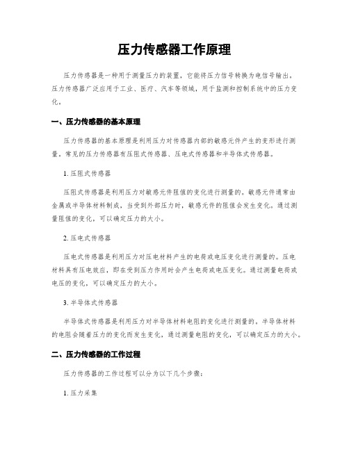
压力传感器工作原理压力传感器是一种用于测量压力的装置,它能将压力信号转换为电信号输出。
压力传感器广泛应用于工业、医疗、汽车等领域,用于监测和控制系统中的压力变化。
一、压力传感器的基本原理压力传感器的基本原理是利用压力对传感器内部的敏感元件产生的变形进行测量。
常见的压力传感器有压阻式传感器、压电式传感器和半导体式传感器。
1. 压阻式传感器压阻式传感器是利用压力对敏感元件阻值的变化进行测量的。
敏感元件通常由金属或半导体材料制成,当受到外部压力时,敏感元件的阻值会发生变化。
通过测量阻值的变化,可以确定压力的大小。
2. 压电式传感器压电式传感器是利用压力对压电材料产生的电荷或电压变化进行测量的。
压电材料具有压电效应,即在受到压力作用时会产生电荷或电压变化。
通过测量电荷或电压的变化,可以确定压力的大小。
3. 半导体式传感器半导体式传感器是利用压力对半导体材料电阻的变化进行测量的。
半导体材料的电阻会随着压力的变化而发生变化,通过测量电阻的变化,可以确定压力的大小。
二、压力传感器的工作过程压力传感器的工作过程可以分为以下几个步骤:1. 压力采集压力传感器首先需要采集外部的压力信号。
这可以通过传感器上的压力接口或压力导管来实现。
当外部压力作用于传感器时,传感器的敏感元件会受到压力的作用而发生变形。
2. 信号转换传感器的敏感元件发生变形后,会产生相应的物理信号,如电阻变化、电荷变化或电压变化。
这些物理信号需要经过信号转换电路进行处理,将其转换为可供测量和分析的电信号。
3. 信号处理经过信号转换后,传感器输出的电信号需要进行进一步的处理。
这包括放大、滤波、线性化等处理步骤,以确保输出信号的准确性和稳定性。
4. 数据输出经过信号处理后,传感器将最终的压力信号以电信号的形式输出。
这些电信号可以是模拟信号或数字信号,可以通过模拟输出接口或数字输出接口传输给其他设备或系统进行进一步的处理和分析。
三、压力传感器的应用领域压力传感器在各个领域都有广泛的应用,下面以几个典型的应用领域为例进行介绍:1. 工业领域在工业领域,压力传感器被广泛用于监测和控制系统中的压力变化。
传感器安装与焊接时的注意事项

传感器安装与焊接时的注意事项传感器的处理和安装有很多方面,这对于实现最佳传感器性能至关重要。
这些元素包括湿度敏感性,ESD考虑因素,机械冲击的影响,以及物理安装,放置和焊接。
本文是关于传感器的焊接,处理,保护和安装的“注意事项”的非详尽概述。
它包括有用的提示,以及有关可以找到其他数据以做出明智决策和协助避免不必要问题的位置的信息。
湿度敏感度等级(MSL)在NI/JEDEC J-STD-020D.1“联合工业标准:非密封固态表面贴装器件的湿度回流灵敏度分类”中建立并描述了湿度敏感度等级。
¹这些水平很重要,因为当封装暴露在焊料回流的高温下时,非密封封装内的水分蒸气压会急剧增加。
包装材料与模具的分层,内部裂缝,粘合损坏,钢丝缩颈,粘合提升,模具提升,薄膜开裂以及粘合下方的缩孔是可能发生的一些问题。
在严重的情况下,水分引起的压力会导致“爆米花”现象,内部压力会导致包装膨胀和破裂,产生可听见的爆音。
这通常发生在SMD设备上。
同样重要的是IPC/JEDEC J-STD-033A“联合工业标准:水分/回流敏感表面贴装器件的处理,包装,运输和使用”,它建立了正确的处理技术。
例如,在环境温度≤30°C/60%RH 下,典型的工厂地板寿命为一周。
静电放电(ESD)如今,许多传感器都内置了ESD保护电路,可以承受2,000 V的人体模型(HBM)静电放电。
仍应遵守JESD625A“处理静电放电敏感器件的要求”³中规定的适当ESD处理。
机械冲击传感器封装或元件落在坚硬的表面上并不是一般的。
当组件从高于5厘米的高度落下时,或者如果硬组件在组装过程中直接撞击它们,则应丢弃它们。
芯片射击器和IC放置器也可能产生重复冲击,这些冲击可能超过某些传感器的生存能力。
建议使用塑料或柔性尖端取放喷嘴,而不是金属喷嘴。
传感器应该是放置在PCB上的最后一个元件,并且应该以。
PCB传感器正确的安装与拆卸

Apply grease to the bottom of the sensor before threading it onto the insert 在拧入螺纹之前在传感器底部点胶
DO NOT thread the small end of the stud in first 不要先拧入螺钉较细端
测力方向盘
传感器标定系统
激振器
Sensor Mounting 传感器安装
4
Mounting with Cyanoacrylate胶结安装
Prior to mounting a sensor with cyanoacrylate, ensure that both the sensor and the mounting surface are free of grease, oil or debris. To do this, use acetone to lift any debris and wipe it away with a clean towel. This ensures clean surface to surface mounting. 在传感器用胶水安装之前,确保传感器和安装面都没有油或灰尘。用丙 酮擦除灰尘再用干净纸巾擦干确保安装面干净。
Incorrect – Too much glue can delay setting and cause excess to build up on sides of sensor.
Mounting with Petro Wax石蜡安装
Correct – Small amounts of wax in all four corners 正确-传感器四周各点一些蜡
DO NOT tighten cable by turning sensor – turn cable sheath 不要通过转动传感器来拧紧电缆
10种传感器资料
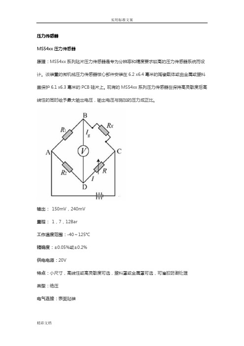
压力传感器MS54xx压力传感器原理:MS54xx系列贴片压力传感器是专为分辨率和精度要求较高的压力传感器系统而设计。
该装置的微机械压力传感器核心部件安装在6.2 x6.4毫米的陶瓷载体或由金属或塑料盖保护6.1 x6.3毫米的PCB硅片上。
现有的MS54xx系列压力传感器在保持高灵敏度后高线性的同时给予最大输出电压,输出电压与施加的压力成正比。
输出:150mV,240mV量程:1,7,12Bar工作温度范围:-40~125℃精确度:±0.05%或±0.2%供电电源:20V特点:小尺寸,高线性或高灵敏度可选,塑料罩或金属罩可选,可灌胶防潮处理类型:绝压电气连接:表面贴装典型应用:绝压测量系统,发动机控制,高分辨率高度计,气压测量计,防水手表,水下计算机,轮胎压力监测系统,医疗器械,充气泵控加速度传感器7114A加速度传感器工作原理是:敏感元件将测点的加速度信号转换为相应的电信号,进入前置放大电路,经过信号调理电路改善信号的信噪比,再进行模数转换得到数字信号,最后送入计算机,计算机再进行数据存储和显示。
当传感元件以加速度a运动时,质量块受到一个与加速度方向相反的惯性力作用,发生与加速度成正比a的形变,使悬臂梁也随之产生应力和应变。
该变形被粘贴在悬臂梁上的扩散电阻感受到。
根据硅的压阻效应,扩散电阻的阻值发生与应变成正比的变化,将这个电阻作为电桥的一个桥臂,通过测量电桥输出电压的变化可以完成对加速度的测量输出:±5V量程:±10g、±50g、±500g封装:不锈钢工作温度范围:-55°C~125°C供电电源:10~30Vdc特点:±10g ~±500g动态量程、带宽可达15kHz、密封焊接、环形剪切、稳定的温度响应、TEDS选项类型:压电IEPE电气连接:电缆典型应用:振动及冲击监测、实验室测试、模型应用、高频应用湿敏传感器HTF3226LF湿敏传感器原理:湿敏电阻的特点是在基片上覆盖一层用感湿材料制成的膜,当空气中的水蒸气吸附在感湿膜上时,元件的电阻率和电阻值都发生变化,利用这一特性即可测量湿度。
26PC

温度补偿传感器 内部结构图
26PC 选型指南
型号
26PCA 26PCB 26PCC 26PCD 26PCF
26PC 型号选择 2
产品系列 2 产品系列
压力范围 psi 1.0 5.0 15 30 100
6 顺序号 6 补偿
校整
引脚编号
1 脚:Vs(+)- 被标明于传感器表面 2 脚:输出(+) 3 脚:接地(-) 4 脚:输出(-)
1 脚:Vs(+) 2 脚:输出(+) 3 脚:接地(-) 4 脚:输出(-)
Pin 1 is notched Pin 2 is next to Pin 1, etc.
推荐型号 26PCAFA6D 26PCBFA6D 26PCBFA6G 26PCCFA6D 26PCCFA6G 26PCDFA6G 26PCFFA6G 26PCFFB6G
MOUNTING DIMENSIONS (for reference only)mm/in DIFFERENTIAL SENSOR 1x4 Termination (Style 6) Port Style A, Straigh (only)
24PC CIRCUIT TERMINATION
Honeywell/Commercial Switch&Sensor 霍尼韦尔商业开关与传感器
2 引脚形式
2 2x2 6 1x4 (0.6" 长)
过压 psi,max
20 20 45 60 200
G 压力形式 G 表压 D 差压
Honeywell/Commercial Switch&Sensor 霍尼韦尔商业开关与传感器
压力传感器- FS系列触力传感器 1500g 的使用说明书
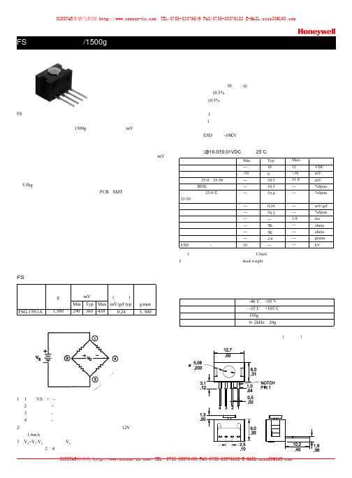
压力传感器FS 系列触力传感器能够在小型商用级别封装下提供精确、可靠的触力传感功能,传感器内含已技术成熟的经特殊微切削硅传感芯片,低功耗、无放大、无补偿的惠斯顿电桥设计在1500g 量程中输出恒定的mV 信号。
传感器的工作原理为:离子注入的压敏电阻受压弯曲时阻值发生变化,并正比于所施加的触力,触力是通过不锈钢插杆直接作用于传感器内部的硅敏感芯片,桥路电阻阻值正比与触力大小,桥路各电阻的变化产生对应的mV 输出信号。
传感器运用专利的模块结构,创新的弹性技术及工程模塑材料使传感器能承受5.5kg 的过压,不锈钢插杆提供极为优秀的机械稳定性,能适合各种应用场合,各种电气连接方式,包括预联线、PCB 、SMT 安装方式,传感器独特的设计能提供包括安装支架在内的多种可选项,也可根据客户要求特制。
典型运用:●医疗吸引泵● 肾透析仪● 机械手● 可调张力控制● 负载或压缩测量● 接触传感FS 传感器选型型号FSG-15N1A触力范围g1,500Min290Typ 360灵敏度(典型值)mV/grf typ.0.24过压g,max 5, 500引脚编号1、 1脚:VS (+)-被标明于引脚表面2脚;输出(+)3脚;接地(-)4脚:输出(-)2、 传感器可恒压或恒流供电,最大供电电压不超过12V ,最大供电电流不超过1.6mA 。
特点:● 紧凑的商业级封装●极低的偏差(典型值30微米@满量程)● 低重复性误差 (0.5%满量程)● 低线性误差 (0.5%满量程)● 低负载中心点偏离误差● 最小分辨率1克● 快速响应(1毫秒)● 低功耗● 很高的抗ESD 能力-10KV技术规格:@10.0±0.01VDC 供电,25˚C电源零点偏置零点漂移,25-0,25-50线性度,BFSL ,灵敏度温漂,25-0˚C 25-50灵敏度重复性反应时间输入阻抗输出阻抗重量ESD (直接接触-引脚与插杆)Min.----30---------------------------10Typ.100±0.5±0.5±5.00.24±0.2---5K 5K 2.0---Max.12+30±1.0------------1.0------------单位VDC mV mV %Span %SpanmV/grf %Span ms ohms ohms grams kV注:1、无补偿的触力传感器当恒流供电(1.5mA )时,能补偿部分温漂。
无引线封装的SOI压阻式压力传感器设计
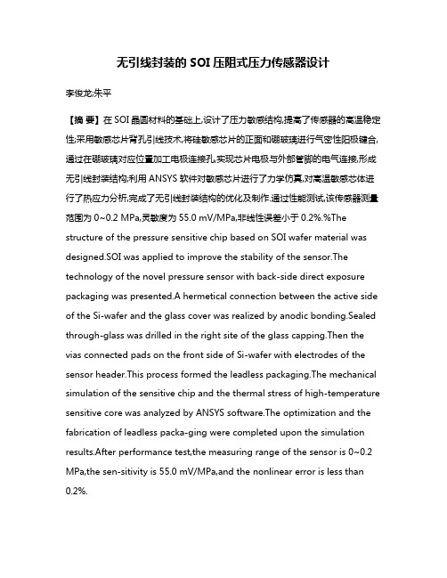
无引线封装的SOI压阻式压力传感器设计李俊龙;朱平【摘要】在SOI晶圆材料的基础上,设计了压力敏感结构,提高了传感器的高温稳定性;采用敏感芯片背孔引线技术,将硅敏感芯片的正面和硼玻璃进行气密性阳极键合,通过在硼玻璃对应位置加工电极连接孔,实现芯片电极与外部管脚的电气连接,形成无引线封装结构;利用ANSYS软件对敏感芯片进行了力学仿真,对高温敏感芯体进行了热应力分析,完成了无引线封装结构的优化及制作.通过性能测试,该传感器测量范围为0~0.2 MPa,灵敏度为55.0 mV/MPa,非线性误差小于0.2%.%The structure of the pressure sensitive chip based on SOI wafer material was designed.SOI was applied to improve the stability of the sensor.The technology of the novel pressure sensor with back-side direct exposure packaging was presented.A hermetical connection between the active side of the Si-wafer and the glass cover was realized by anodic bonding.Sealed through-glass was drilled in the right site of the glass capping.Then the vias connected pads on the front side of Si-wafer with electrodes of the sensor header.This process formed the leadless packaging.The mechanical simulation of the sensitive chip and the thermal stress of high-temperature sensitive core was analyzed by ANSYS software.The optimization and the fabrication of leadless packa-ging were completed upon the simulation results.After performance test,the measuring range of the sensor is 0~0.2 MPa,the sen-sitivity is 55.0 mV/MPa,and the nonlinear error is less than 0.2%.【期刊名称】《仪表技术与传感器》【年(卷),期】2017(000)012【总页数】5页(P20-24)【关键词】无引线封装;绝缘体上硅(SOI);压阻式压力传感器;背孔引线;有限元分析(FEA);耦合仿真【作者】李俊龙;朱平【作者单位】中北大学仪器与电子学院,山西太原 030051;中北大学仪器与电子学院,山西太原 030051【正文语种】中文【中图分类】TP2120 引言随着MEMS技术的发展,在微小型硅高温压力传感器领域,SOI晶圆材料因其优良的高温特性成为制作高温器件的首选材料[1]。
pcb压力传感器手册
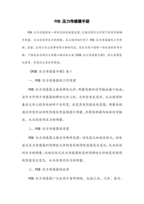
PCB 压力传感器手册PCB 压力传感器是一种常见的传感器类型,它通过将外力作用下的变形转换为电量,从而实现对压力的测量。
本文档详细介绍了 PCB 压力传感器的工作原理、类型、应用以及注意事项等方面的内容,旨在为用户提供一份实用的参考手册。
下面是本店铺为大家精心编写的4篇《PCB 压力传感器手册》,供大家借鉴与参考,希望对大家有所帮助。
《PCB 压力传感器手册》篇1一、PCB 压力传感器的工作原理PCB 压力传感器主要由弹性元件、测量电路和信号输出接口组成。
当外力作用于传感器的弹性元件上时,元件会发生变形,从而使得附着在元件上的导电材料产生形变,改变其电阻值或电容值。
测量电路通过对变形后的电阻值或电容值进行测量,并将其转换为标准信号输出,从而实现对压力的测量。
二、PCB 压力传感器的类型PCB 压力传感器主要分为两种类型:硅电容式和硅压阻式。
硅电容式压力传感器利用弹性元件的变形使得电容值发生变化,从而实现对压力的测量。
而硅压阻式压力传感器则是利用弹性元件的变形使得电阻值发生变化,从而实现对压力的测量。
三、PCB 压力传感器的应用PCB 压力传感器广泛应用于各种领域,包括工业、汽车、医疗、家电等。
其中,PCB 压力传感器在工业生产中的应用最为广泛,如在自动化设备、流程控制、液压系统等方面。
此外,PCB 压力传感器还可用于汽车的制动系统、燃油喷射系统等,以及医疗领域的呼吸机、监护仪等设备中。
四、PCB 压力传感器的使用注意事项1. 选择合适的 PCB 压力传感器:在使用 PCB 压力传感器时,应根据实际需求选择合适的传感器类型和量程。
2. 安装与接线:在安装 PCB 压力传感器时,应注意将其固定牢固,并确保接线正确无误。
3. 避免冲击与振动:PCB 压力传感器在受到冲击或振动时容易损坏,因此在使用过程中应尽量避免。
4. 维护与保养:定期对 PCB 压力传感器进行清洁和保养,以确保其正常工作和延长使用寿命。
PCB Piezotronics 102B ICP 压力传感器安装与操作手册说明书

Model 102BICP® Pressure SensorInstallation and Operating ManualFor assistance with the operation of this product, contact PCB Piezotronics, Inc.Toll-free: 800-828-884024-hour SensorLine: 716-684-0001Fax: 716-684-0987E-mail:************Web: The information contained in this document supersedes all similar information that may be found elsewhere in this manual.Service –Due to the sophisticated nature of the sensors and associated instrumentation provided by PCB Piezotronics, user servicing or repair is not recommended and, if attempted, may void the factory warranty. Routine maintenance, such as the cleaning of electrical connectors, housings, and mounting surfaces with solutions and techniques that will not harm the physical material of construction, is acceptable. Caution should be observed to ensure that liquids are not permitted to migrate into devices that are not hermetically sealed. Such devices should only be wiped with a dampened cloth and never submerged or have liquids poured upon them.Repair –In the event that equipment becomes damaged or ceases to operate, arrangements should be made to return the equipment to PCB Piezotronics for repair. User servicing or repair is not recommended and, if attempted, may void the factory warranty.Calibration –Routine calibration of sensors and associated instrumentation is recommended as this helps build confidence in measurement accuracy and acquired data. Equipment calibration cycles are typically established by the users own quality regimen. When in doubt about a calibration cycle, a good “rule of thumb” is to recalibrate on an annual basis. It is also good practice to recalibrate after exposure to any severe temperature extreme, shock, load, or other environmental influence, or prior to any critical test.PCB Piezotronics maintains an ISO- 9001 certified metrology laboratory and offers calibration services, which are accredited by A2LA to ISO/IEC 17025, with full traceability to SI through N.I.S.T. In addition to the normally supplied calibration, special testing is also available, such as: sensitivity at elevated or cryogenic temperatures, phase response, extended high or low frequency response, extended range, leak testing, hydrostatic pressure testing, and others. For information on standard recalibration services or special testing, contact your local PCB Piezotronics distributor, sales representative, or factory customer service representative.Returning Equipment –Following these procedures will ensure that your returned materials are handled in the most expedient manner. Before returning any equipment to PCB Piezotronics, contact your local distributor, sales representative, or factory customer service representative to obtain a Return Warranty, Service, Repair, and Return Policies and Instructions Materials Authorization (RMA) Number. This RMA number should be clearly marked on the outside of all package(s) and on thepackinglist(s) accompanying the shipment. A detailed account of the nature of the problem(s) being experienced with the equipment should also be included inside the package(s) containing any returned materials.A Purchase Order, included with the returned materials, will expedite the turn-around of serviced equipment. It is recommended to include authorization on the Purchase Order for PCB to proceed with any repairs, as long as they do not exceed 50% of the replacement cost of the returned item(s). PCB will provide a price quotation or replacement recommendation for any item whose repair costs would exceed 50% of replacement cost, or any item that is not economically feasible to repair. For routine calibration services, the Purchase Order should include authorization to proceed and return at current pricing, which can be obtained from a factory customer service representative.Contact Information –International customers should direct all inquiries to their local distributor or sales office. A complete list of distributors and offices can be found at . Customers within the United States may contact their local sales representative or a factory customer service representative. A complete list of sales representatives can be found at . Toll-free telephone numbers for a factory customer service representative, in the division responsible for this product, can be found on the title page at the front of this manual. Our ship to address and general contact numbers are:PCB Piezotronics, Inc.3425 Walden Ave.Depew, NY14043 USAToll-free: (800) 828-884024-hour SensorLine SM: (716) 684-0001 Website: E-mail:************PCB工业监视和测量设备 - 中国RoHS2公布表CHINA RoHS COMPLIANCEDOCUMENT NUMBER: 21354 DOCUMENT REVISION: D ECN: 46162Drawing Number: 21075Revision: CECN Number: 47023 1.0 INTRODUCTIONThis series of miniature dynamic pressure sensors is specifically designed for shock tube and blast wave measurements and for other applications requiring very high frequency, near non-resonant response.The term used to describe the transient response of this model series is “Frequency Tailoring” and it encompasses several mechanical and electrical design features coupled with stringent in-process fabrication/test procedures with heavy emphasis on the shock tube as a tool.2.0 DESCRIPTIONAlthough this series consists of sensors with three basic mechanical configurations and six different sensitivities, each model is basically similar in internal design.Typical ICP ® Probe Style SensorEach utilizes the acceleration-compensated Series 113 quartz piezoelectric element coupled to a source follower type miniature electronics. (See “General Guide to ICP ® Instrumentation,” G -0001B, for a detailed description of the ICP ® concept.)The figure above shows the components of the basic ICP ® probe, i.e. the piezoelectric element and the ICP ® source follower amplifier. These components are joined together as an inseparable sealed assembly at the factory. Disassembly should not be attempted in the field. Series 113B2x are in a probe configuration and are installed with a hollow clamp nut with 5/16-24 external threads. The housing of these models is at electrical ground potential. Series 113B3x are similar to the B2x Series with an additional feature; all Invar construction. The all Invar sensors are designed to have minimal susceptibility to thermal transient events and are specifically suited for high-temperature shock and blast measurements. Series 113: Probe Style Sensor Series 102 consist of the basic 113 Series probe, as in the above mentioned series, mounted in a 3/8-24 threaded mounting adaptor. The probe is installed at the factory in an "off ground" configuration, i.e. the probe body is insulated from the external mounting adaptor body. The Model 102A12 utilizes the same inner probe design as the above two designs but in a 3/8-24Seal Ring Potting Preload SleeveElectrodes 0.218DiaQuartz AccelerationMass and Mounting Clamp NutDrawing Number: 21075Revision: CECN Number: 47023 adjustment of diaphragm mounting depth where it is necessary to adapt to various wall thicknesses. These models are supplied only as low-pressure (250 psi and 100 psi) sensors and are also "off ground".Models 102A21 and 102A22 are high-temperature ICP ® versions to 400 ︒F (204 ︒C), with a 3/8-24 straight threads adaptor and 1/8-27 NPT adaptor, respectively.Series 102: Thread Mount Design, Ground-Isolated Sensor3.0 INSTALLATIONThis manual contains outline and installation information for your specific model.Prepare mounting ports in accordance with instructions given in specific installation drawings, paying particular attention to sealing surfaces. These surfaces must be smooth and free from chatter marks, nicks and other irregularities which could preclude a pressure tight seal.To fully realize the high-frequency response capabilities of this sensor series, flush mounting of the diaphragm must be used.In some cases, where flash temperatures such as those generated by blasts and shock fronts are present, it may be necessary to thermally insulate the diaphragm to minimize signals generated by these effects.be an effective insulating material in many cases. One or more layers may be used across the end of diaphragm and adaptor. A silicone rubber coating approximately .010” thick has also been proven effective in many applications. General Electric RTV type 106 is recommended. Apply the rubber coating to the surface of the diaphragm and allow it to cure in accordance with the manufacturer’s instructions. (If you have ordered the CA option, ablative coated models, further protection will not be necessary.) Although ICP ® sensors have low-output impedance and in general are not affected by moisture, in extreme environments it is good practice to protect cable connections with shrink tubing. It is not necessary to use low-noise cable with this sensor series. In fact, an optional Model 070B09 Solder Connector Adaptor allows the use of ordinary two-wire cable if desired. 4.0 OPERATION It is only necessary to supply the sensor with a 2 to 20 mA constant current at +20 to +30 VDC through a current-regulating diode or equivalent circuit. (See guide G-0001B for powering and signal utilization information pertaining to all ICP ® instrumentation). Most of the signal conditioners manufactured by PCB have an adjustable current feature allowing a choice of input currents from 2 to 20 mA. In general, for lowest noise (best resolution), choose the lower current ranges. For driving long cables (to several thousand feet), use higher current, up to 20 mA maximum. To operate system using a PCB signal conditioner: 1. Switch power on. 2. Wait several minutes for the IC ampli- fier to turn on and stabilize. 3. Proceed with measurements.Drawing Number: 21075Revision: CECN Number: 47023 5.0 POLARITYThe sensors in this series produce a positive-going output voltage for increasing pressure input.6.0 LOW-FREQUENCY RESPONSEThe low-frequency response of an ICP ® system is determined by:1. The discharge T.C. of the sensor2. If AC-coupled at power unit, the coupling time constant.Consult Section 7.0 in guide G-0001B detailed explanation of low-frequency characteristics of ICP ® instruments.7.0 HIGH-FREQUENCY RESPONSEFrequency tailoring and the very high-natural frequency of the sensor give an extremely wide usable frequency range (beyond 100 kHz). Exceptionally fast response time (1 µsec) and clean, virtually non-resonant response to rapid step functions are also features of these sensors. As mentioned previously, the diaphragm must be flush-mounted to fully realize the high-frequency response capabilities of this series.8.0 CALIBRATIONPiezoelectric sensors are dynamic devices, but static calibration means can be employed if discharge time constants are sufficiently long. Generally, static methods are not employed below several hundred seconds time constant.To employ static means, direct couple the sensor to the DVM readout using a T-Connector from the sensor jack or use the Model 484B in the calibrate mode. Apply pressure with dead weight tester and take readings quickly. Release pressure after each calibration point.For the shorter time constant, rapid step functions of pressure are generated by a pneumatic pressure pulse recorder or storage oscilloscope. PCB offers a complete calibration service. Consult factory for details. ICP is a registered trademark of PCB Piezotronics。
- 1、下载文档前请自行甄别文档内容的完整性,平台不提供额外的编辑、内容补充、找答案等附加服务。
- 2、"仅部分预览"的文档,不可在线预览部分如存在完整性等问题,可反馈申请退款(可完整预览的文档不适用该条件!)。
- 3、如文档侵犯您的权益,请联系客服反馈,我们会尽快为您处理(人工客服工作时间:9:00-18:30)。
pcb封装压力传感器
pcb封装压力传感器
高导热LED铝基线路板、FR-4玻纤线路板、PCB线路板;
产品应用:大功率LED路灯,射灯,日光灯,洗墙灯与电子产品等!
铜箔厚度:1/2-6盎司;
线路层数:1-16层;
最小线宽:0.1mm(4 mils);
最小线距:0.1mm(4 mils) ;
最小孔径:0.25mm(10 mils) ;
线路转移:曝光线路(湿膜、干膜)、丝印线路;
板材厚度:0.8mm-3.0mm;
表面工艺:镀金、喷锡、沉金、松香、抗氧化;
防焊油墨: 感光、热、UV光固化油墨;
热风整平:单面及双面;
pcb封装压力传感器
Model 2301-01A 2301-02A 2302-01A 2302-02A 2303-01A 2303-02A
Model 2304-01A 2304-02A 2305-01A 2305-02A 2308-01A 2308-02A
Model 2308-03A 2309-01A 2309-02A 2309-03A 2309-04A 2508-01A
Model 2508-02A 2508-03A 2508-04A 2508-05A 2525-02A 2525-102-03A
Model 2526-04A 4102-01A 4102-02A 4102-03A 4102-04A 4102-05A
Model 4103-01A 4103-02A 4104-01A 4104-02A 4104-03A 4105-01A
Model 4105-02A 4105-03A 4106-01A 4106-02A 4106-03A 4107-01A
Model 4107-02A 4107-03A 4115A-01A 4115A-03A 4115A-04A 4115A-02A
Model 4115A-05A 4115K-01A 4115K-02A 4115K-03A 4115K-04A 4115K-05A
PCB称重传感器;PCB力传感器:
Model 1233-01B 200B01 200B02 200B03 200B04 200B05 200C20 200C50 201A76 201A75 201B01
Model 201B02 201B03 201B04 201B05 202B 203B 204C 205C 206C 207C 208A11 208A12 Model 208A13 208A14 208A15 208A22 208A23 208A24 208A33 208A45 208C01 208A35 208B01 Model 208C02 208B02 208C03 208B03 208C04 208B04 208C05 208B05 209C01 209C02 209C11 Model 209C12 210B 210B20 210B50 211B 212B 213B 214B 215B 216B 217B 218A11 218C Model 219A05 221B01 221B02 221B03 221B04 221B05 222B 223B 224C 225C 226C 227C 231B Model 232B 233B 234B 235B 236B 237B 260A01 260A02 260A03 260A11 260A12 260A13 260A31
Model 260A32 260A33 261A01 261A02 261A03 261A11 261A12 261A13 6244-107-02A RH201A76
Model RH204C W208C01/002C10 W208C04/002C10 W208C05/002C10 240A01 240A02 240A03 740B02
Model RH240A01 RH240A02 RH240A03
pcb封装压力传感器
PCB显示仪表;PCB信号放大器;PCB信号调理器:
Model 070A80 100A02 401B04 410B01 421A25 422E01 422E02 422E03 422E04 422E05 422E06 Model 422E11 422E12 422E13 422E14 422E15 422E16 422E20 422E21 422E22 422E35 422E36 Model 422E38 422E51 422E52 422E53 422E54 422E55 422E65/A 422E66/A 427A03 442B06 Model 442C04 443B01 478A01 478A30 478B05 480B21 480A21 480C02 480E09 481A 481A01 Model 481A02 481A03 482A21 482A22 482A23 482B11 482C05 482B05 482C16 482C15 482C26 Model 482C54 482C64 483C05 483C15 483C30 483C50 484B02 484B06 485B36 485B36 498A Model 498A01 498A02 498A03 498A30 682A02 682A06 682A71-01 682A72-01 8120-400A Model 8120-410A 8120F-410A 8120G-400A 8159-0011A 8159-0012A 8159-0013A 8159-0112A Model 8160-01A 8161-011A 8162-011A T422E91/A T422E92/A T422E93/A
pcb封装压力传感器
pcb封装压力传感器
MAF-01 MAF-02 MAF-03
剥离强度N/㎜热应力后1.80 1.90 1.90
表面是阻MΩ交收态7×10⁹ 5×10⁹ 5×10⁸
C-96/35/90 3×10⁹ 2×10⁹ 4×10⁸
体积电阴率MΩ.m 交收态4×10⁸ 2×10⁹ 8×10⁹
C-96/35/90 5×10⁸ 5×10⁸ 2×10⁹
热阻℃/W A 1.5 1.2 1.0
介电常数—交收态4.0 3.9 3.5
介电损耗因数—交收态0.028 0.026 0.009
导热系数W/m.℃交收态1.2
耐浸焊性min 288℃60 min,不分层,不起泡
击穿电压KW D-48/50+D/0.5/23 3.5
燃烧性—交收态V-0
耐电弧S 交收态280
以上内容技术参数以《OIML60号国际建议》92年版为基础,最新具体变化可查
看《JJG669—12 美国pcb广州南创传感器事业部检定规程》。