施乐百EC风机控制器使用说明-2014.7.2
施乐 维萨连 彩色多功能一体机 C7000系列 使用指南说明书

C 7020/C 7025/C 7030Xerox ®VersaLink ®Color Multifunction PrintersReliable. Connected. Business Ready.F L AW L E S S R E L I A B I L I T Y.S U P E R I O R P E R F O R M A N C E.Count on your Xerox® VersaLink® C7000 Series Color Multifunction Printer to consistently and flawlessly perform the tasks that make your business work more efficiently. From IT-free installation wizards, to step-by-step configuration options, you’re ready togo — hassle free.Superior reliability comes from a new hardware design with fewer moving parts, strengthened paper-path components, and an advanced imaging system.VersaLink® devices speed up information sharing and reduce inefficient workflows. Ensure information accuracy with Scan and Fax preview, easily archive, organize and search with scanned documents with built-in optical character recognition (OCR).A print resolution of up to 1200 x 2400 dpi delivers sharp text and fine line detail, plus exceptional color vibrancy, solid fills and skin tones.C L O UD C O N NE C T E D.P E R S O N A L I Z E D E F F I C I E N C Y.The customizable 7-inch color touchscreen, lets you breeze through tasks withmobile-like ease.Xerox® ConnectKey® Apps, accessed via the extensive Xerox App Gallery, provide expanded functionality — like the optional Xerox® Easy Translator Service app, which quickly translates scanned documents into numerous languages.Get more done in less time by creating customized 1-Touch Apps to automatemulti-step workflows for individuals or groups. Simply tap your new app to quickly perform the job you configured.And with Simple ID, individual users and groups enter a user ID and password once, and then enjoy fast, secure access totask-specific presets, individualized favorite contacts, and commonly used apps on a personalized home screen.R E A DY F O R T H E WAY YO U W O R K.The VersaLink® C7000 Series gives youthe freedom to work where and how you want — with access to Google Drive™, Microsoft®OneDrive® and DropBox™ and additional options through the Xerox App Gallery. VersaLink® devices deliver for today's mobile worker with Apple® AirPrint®, Google Cloud Print™, Xerox® Print Services plug-in for Android™, Near Field Communication (NFC) Tap-to-Pair and Mopria®, plus optional Wi-Fi and Wi-Fi Direct.Learn more about why Xerox is the only choice for today’s mobile professionals by visiting /Mobile.E N V I R O N M E N TA L S T E WA R D S H I P. VersaLink® devices meet or exceed the requirements of the world's most widely recognized certifications for product environmental performance, including EPEAT®, which verifies manufacturer claims regarding design, production, energy use and recycling. (See the complete list of EPEAT-verified VersaLink® products.)For more information about our environmental, health, safety and sustainability efforts, visit .Xerox® VersaLink® C7020/C7025/C7030Color Multifunction PrinterThe Xerox® ConnectKey® Technology-enabled VersaLink®C7000 Series Color Multifunction Printer is cloud connected,mobile ready, app-enabled and easy to personalize. The C7000Series is your modern workplace assistant — helping youexcel today and stay ready for the future.To learn more about VersaLink® device features,go to /VersaLinkEG.F I N I S H I NG A P P L I C AT I O N S1 A 110-sheet Duplex Automatic Document Feeder (DADF) scans two-sided black-and-white or color originals for copy, scan and fax jobs.2 T he optional Convenience Stapler and Work Surface .3 C ard Reader Bay with embedded USB port.14 A n easily accessible USB port 1 allows users to quickly print from or scan to any standard USB memory device.5 T he 100-sheet Bypass Tray handles media sizes from 3.5 x 3.87 in. to 11.69 x 17 in./88.9 x 98.4 mm to 297 x 431.8 mm.6 T he standard 520-sheet Tray 1 handles media sizes from 5.5 x 7.17 in. to 11.69 x 17 in./139.7 x 182 mm to 297 x 431.8 mm.1USB ports can be disabled.M U LT I P L E PA P E R T R AY O P T I O N S T O F I T E V E R Y N E E D :7 T he Single Tray Module (optional with Desktopmodel) increases total paper capacity to 1,140 sheets (includes Bypass Tray). 8 T he optional Single Tray with Stand Moduleincreases total paper capacity to 1,140 sheets(includes Bypass Tray) and provide storage for toner cartridges and other supplies.9 T he optional Three Tray Module increases totalpaper capacity to 2,180 sheets (includes Bypass Tray). The optional High-Capacity Tandem TrayModule (not shown) allows a total paper capacity of up to 3,140 sheets (includes Bypass Tray).10 T he optional High Capacity Feeder holds 2,000sheets of letter/A4 paper, increasing the maximum paper capacity to 5,140 sheets.A D D I N C R E A S E D V E R S AT I L I T Y W I T H F I N I S H I N G O P T I O N S :11 T he Dual Catch Trays (optional withDesktop model) stack up to 250 sheets each, lower tray offsets.12 T he optional Office Finisher gives youadvanced finishing functions at a great value and offers optional booklet making (score, saddle-stitch).13 T he optional Integrated Office Finisherprovides 500-sheet stacking and 50-sheet, dual-position stapling without increasing the footprint of the printer.1234561091268136117I N T R O D U C I N GT O U C H S C R E E N S U P E R I O R I T YMeet our all-new, 7-inch color touchscreen — the user interface that sets a higher standard for customization, personalization and versatility.By presenting a familiar “mobile”experience — with support for gestural input and task-focused apps that share a common look and feel — fewer steps are needed to complete even the most complex jobs.A highly intuitive layout guides you through every task from start to finish, with anatural hierarchy placing critical functions near the top of the screen and commonly used options front and center. Don’t like where a function or app is located? Customize the layout to make it yours.This unmatched balance of hardware technology and software capability helps everyone who interacts with the VersaLink ® C7000 Series Color Multifunction Printer get more work done, faster.For more detailed specifications, go to /VersaLinkC7000Specs .© 2021 Xerox Corporation. All rights reserved. Xerox®, ConnectKey®, DocuShare®, Global Print Driver®, VersaLink® and Xerox Extensible Interface Platform® are trademarks of Xerox Corporation in the United States and/or other countries. The information in this brochure is subject to change without notice. 05/21 TSK-1864 BR26548 VC7BR-01UED E V I C E S P E C I F I C AT I O N SV E R S A L I N K ® C 7020V E R S A L I N K ® C 7025V E R S A L I N K ® C 7030Speed 1Up to 20 ppm Up to 25 ppm Up to 30 ppmMonthly Duty Cycle 2Up to 87,000 pages 2Up to 107,000 pages 2Up to 129,000 pages 2 Hard Drive/Processor/Memory 320 GB HDD 6/1.05 GHz Dual-core/4 GB memoryConnectivityEthernet 10/100/1000 Base-T, High-speed USB 3.0, Wi-Fi ® and Wi-Fi Direct ® with optional Wi-Fi Kit, NFC Tap-to-PairController FeaturesUnified Address Book, Configuration Cloning, Scan Preview, Xerox Extensible Interface Platform ®, Xerox ® App Gallery App, Xerox ® Standard Accounting Tool, Role Based Permissions, Convenience Authentication Enabled, Online Support Copy and Print Resolution Copy: Up to 600 x 600 dpi; Print: Up to 1200 x 2400 dpi First-Copy-Out Time (as fast as)As fast as 9.0 seconds color/6.9 seconds black-and-white As fast as 7.2 seconds color/5.8 seconds black-and-whiteFirst-Print-Out TimeAs fast as 9.4 seconds color/ 7.2 seconds black-and-white As fast as 9.4 seconds color/ 7.1 seconds black-and-white As fast as 7.3 seconds color/ 5.6 seconds black-and-white Page Description Languages PCL ® 5e/PCL 6/PDF/XPS/TIFF/JPEG/HP-GL/optional Adobe ® PostScript ® 3™Paper Input StandardDuplex Automatic Document Feeder (DADF): 110 sheets: Speed: up to 55 ipm; Custom sizes (duplex): 4.92 x 4.33 in. to 11.69 x 17 in./ 125 x 110 mm to 297 x 431.8 mm; Custom sizes (simplex): 4.92 x 3.35 in. to 11.69 x 17 in./125 x 85 mm to 297 x 431.8 mm Bypass Tray: 100 sheets; Custom sizes: 3.5 x 3.87 in. to 11.69 x 17 in./88.9 x 98.4 mm to 297 x 431.8 mm Tray 1: 520 sheets; Custom sizes: 5.5 x 7.17 in. to 11.69 x 17 in./139.7 x 182 mm to 297 x 431.8 mmChoose OneSingle Tray Module: 520 sheets; Custom sizes: 5.5 x 7.17 in. to 11.69 x 17 in./139.7 x 182 mm to 297 x 431.8 mm Single Tray with Stand: 520 sheets; Custom sizes: 5.5 x 7.17 in. to 11.69 x 17 in./139.7 x 182 mm to 297 x 431.8 mmThree Tray Module (1,560 sheets): 520 sheets each; Custom sizes: 5.5 x 7.17 in. to 11.69 x 17 in./139.7 x 182 mm to 297 x 431.8 mmHigh Capacity Tandem Tray (2,520 sheets): Tray 2: 520 sheets; Custom sizes: 5.5 x 7.17 in. to 11.69 x 17 in./139.7 x 182 mm to 297 x 431.8 mm; Tray 3: 870 sheets; Standard sizes: 8.5 x 11 in. and 7.25 x 10.5 in./A4 or B5; Tray 4: 1,130 sheets; Standard sizes: 8.5 x 11 in. and 7.25 x 10.5 in./A4 or B5OptionalEnvelope Tray: Up to 60 envelopes: #10 commercial, Monarch, DL, C5; Custom sizes: 3.9 x 5.8 in. to 6.4 x 9.5 in./98 x 148 mm to 162 x 241 mm High Capacity Feeder (HCF): 2,000 sheets; Standard sizes: 8.5 x 11 in. and 7.25 x 10.5 in./A4 or B5Paper Output/ Standard FinishingOptionalDual Catch Tray 6: 250 sheets each; Lower tray offsetsIntegrated Office Finisher: 500-sheet stacker, 50 sheets stapled, dual-position staplingOffice Finisher : 2,000-sheet stacker, 50 sheets stapled, 3-position stapling, optional hole-punch, optional booklet maker (score, saddle stitch) Convenience Stapler and Work Surface: Staples 50 sheetsI N T U I T I V E U S E R E X P E R I E N C ECustomize and Personalize Walkup customization, Personalize Home Screen by User, Multiple Home Screens with Simple ID, Customize by Site, and Function or Workflow with Xerox App GalleryPrint DriversJob Identification, Bi-directional Status, Job Monitoring and Xerox ® Global Print Driver ®Embedded Web Server PC or mobile — Status Information, Responsive Design, Settings, Device Management, Cloning Remote Console Remote Control PanelPreviewPreview of Scan/Fax with Zoom, Rotate, Add PagePrint Features Print from USB, Secure Print, Sample Set, Personal Print, Saved Job, Earth Smart Driver Settings, Job Identification, Booklet Creation, Store and Recall Driver Settings, Bi-directional Real-time Status, Scaling, Job Monitoring, Application Defaults, Two-sided Printing (as default), Skip Blank Pages, Draft Mode Scan Optical Character Recognition (OCR), Scan to USB/Email/Network (FTP/SMB), Scan File Formats: PDF, PDF/A, XPS, JPEG, TIFF; Convenience Features: Scan to Home, Searchable PDF, Single/Multi-Page PDF/XPS/TIFF/Password Protected PDFFax 3Optional Walk-up Fax (one-line or three-line options available, includes LAN Fax, Direct Fax, Fax Forward to Email, Server Fax), optional Fax Over IP M O B I L E A N D C L O U D R E A D YMobile Printing Apple ® AirPrint ®4, Mopria ® Certified, Mopria ® Print Services plug-in for Android™, Xerox ® @printbyXerox App, Xerox ® Print Services plug-in for Android™Mobility Options Xerox ® Mobile Print and Mobile Print Cloud, Connect via NFC/Wi-Fi Direct Printing, Xerox ® Mobile Link App. Visit /OfficeMobileApps for available appsCloud Connectors 5Print from/Scan to Google Drive™, Microsoft ® OneDrive ®, Dropbox™, Microsoft Office 365®, Box ®, Xerox ® DocuShare ® Platform and moreB E NC H M A R K S E C U R I T YNetwork Security IPsec, HTTPS, encrypted email. Network Authentication, SNMPv3, SSL/TLS, Security Certificates, Pre-installed Self-signed Certificates, Cisco ® Identity Services Engine (ISE) integrationDevice Access Firmware Verification, User access and internal firewall, Port/IP/Domain Filtering, Audit Log, Access Controls, User Permissions, Smart Card Enabled (CAC/PIV/.NET), Xerox ® Integrated RFID Card Reader, Trusted Platform Module (TPM)Data Protection Setup/Security Wizards, Job Level Encryption via HTTPS/IPPS submission, Encrypted hard disk (AES 256-bit, FIPS 140-2) and image overwrite, Common Criteria Certification (ISO 15408), Encrypted Apps with Embedded Certificate Support Document Security Secure Print, Secure Fax, Secure Email, Password Protected PDFE N A B L E S N E X T G E N E R A T I O N S E R V I C E SPrint Management Xerox ® Standard Accounting Tool, Optional: Xerox ® Workplace Cloud/Suite, Nuance Equitrac, Ysoft SafeQ, PaperCut and more at /PrintManagementFleet/Device Management Xerox ® Device Manager, Xerox ® Support Assistant App, Auto Meter Read, Managed Print Services tools, Configuration Cloning Sustainability Cisco EnergyWise ®, Earth Smart Printing, EPEAT-verified, Print User ID on marginsG A T E W A Y T O N E W P O S S I B I L I T I E SCloud Services Xerox ® Translate and Print, Xerox ® Healthcare MFP Solution (U.S. only), CapturePoint™, many additional services availableXerox App GalleryMany apps and cloud services available. Visit /AppGallery for a growing selection of Xerox ® apps available for adding functions.1 Declared print speed in accordance with ISO/IEC 24734.2 Maximum volume capacity expected in any one month. Not expected to be sustained on a regular basis;3 Requires analog phone line;4Visit for AirPrint Certification list; 5 Optional download from Xerox App Gallery to the Printer — /XeroxAppGallery ; 6 HDD and Dual Catch Tray are optional on Desktop model.The VersaLink ® C7020/C7025/C7030 Color Multifunction Printer is built on Xerox ® ConnectKey ® Technology. For more information, visit .Xerox ® VersaLink ®C7020/C7025/C7030。
ec风机控制原理
ec风机控制原理EC风机控制原理一、引言EC(Electronically Commutated)风机是一种新型的无刷直流风机,它采用了电子换向技术,能够实现高效节能的风速控制。
本文将详细介绍EC风机的控制原理。
二、EC风机的基本原理EC风机的核心是一台EC电机,它由永磁同步电机和电子换向器组成。
在EC电机中,永磁同步电机负责驱动风机转子转动,而电子换向器则控制电流的方向和大小,从而实现对风机转速的精确控制。
三、EC风机的控制方式EC风机可以通过多种方式进行控制,包括模拟控制和数字控制。
1. 模拟控制模拟控制是通过改变电压或电流的方式来控制EC风机的转速。
通常情况下,EC风机的输入电压范围是0-10V或4-20mA,通过调节输入电压或电流的大小,可以实现对风机转速的调节。
模拟控制通常适用于简单的风机控制场景,但精度较低。
2. 数字控制数字控制是通过发送数字信号来控制EC风机的转速。
数字控制可以通过串行通信接口(如RS485或Modbus)或现场总线(如Profibus或CAN)来实现。
数字控制能够实现对EC风机精确的转速控制,并可以与其他设备进行联动控制。
四、EC风机的控制策略EC风机的控制策略主要包括开环控制和闭环控制。
1. 开环控制开环控制是指EC风机的转速仅由输入信号决定,没有反馈控制。
在开环控制中,控制器根据预设的输入信号,给EC风机提供相应的电压或电流,从而控制其转速。
开环控制简单直接,但在一些特殊情况下(如负载变化较大),容易导致转速不稳定。
2. 闭环控制闭环控制是指EC风机的转速通过反馈信号进行控制。
闭环控制中,EC风机会安装转速传感器,实时监测转速,并将转速信号反馈给控制器。
控制器根据反馈信号与设定值进行比较,并调节输入信号,从而实现对转速的闭环控制。
闭环控制能够更加精确地控制EC风机的转速,提高控制精度和稳定性。
五、EC风机的优势相比传统的交流风机,EC风机有以下几个优势:1. 高效节能:EC风机采用无刷直流电机,具有高效节能的特点。
EC92 User Manual 电机 使用说明书

P05 Attentions P10 P11 Troubleshooti Quick cse _g u ide P04technical p aramete,PO7EC92 Electrostatic Air PurifierP08Speed,_Wlnd speed』wlnd speed ls dlvlded lnto three $talls lt /, ! 勺'as a comsponding wind 5peed,con on the contml panel宅?夕C.gn..,r,dn8加,3d迁n8galfe,gn六m忒心ggh伈”e市,l比n叫$h.2nbucn rdmg`2,汕"tr,noh”e ot9:wg比2hcssn-9勺on心吐.总rob39er�它芒tne'呤尸mkg旧气nCPhdty"戏AeP5cg_htd nhnllt.DnhACUV 芯忑芯芯aloto匹h心1佃nl伍,屈,“'心叩.“四chReset三千a;22二二.0:::立了二二芯°:,·肋飞:二”:车2aho n soquo n cat`O沁“如心.旧庙ou1中heo ld,hmI',/仓,J/夕J3�y芍i忽,/f勾气j'倡冒三,以户、立=n匀罢亏王仁==;_,purify functionI ntelligent ai「purifierfilte『S+8sf tBge pu『ification;::p::三::::三n ep;勹::,c.『e:r”:三:e;f::m5.:.二;i.h l;:「f二:::;u;?'::“二d c a nhepa亡:二,.二“二.二.。
二二°C:二:2:;二二.::::,二勹。
二二:二'.6.p.尸"'"叩r l n,h..凡m喊n l y知tho p心沁9`d P M 2.5. l t h邸·一毗中ngL中^`.l ll a nd l m l l l l l.ca『bon::三三芒芒:'s:0:0,::0:',三三三'",三二三了p:::三:二二can bo中".,...,..芒5三三立:芷二?忒u":二::二。
CS2-PM2.5 CO2 智能控制器说明书(EC)
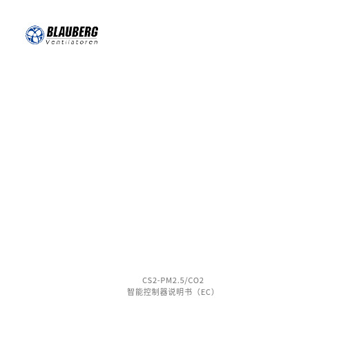
CS2-PM2.5/CO2智能控制器说明书(EC)一、概述CS2-PM2.5/CO2智能控制器采用触摸按键技术,操作灵活方便。
内置传感器能够实时监测室内温度、湿度、PM2.5浓度,以及CO2浓度探测功能,控制器输出信号直接控制新风机的启动及转速,可广泛应用于住宅、商业及工业场合,并且能有效改善空气品质,创造健康、舒适、高效、环保、节能的生活工作环境。
二、按键功能说明1、 键:开关机键2、 键:参数上调键3、键:参数下调键4、 键:开启或关闭风阀5、 键:切换工作模式6、键:设置时钟及定时参数旁通阀状态星期显示室内温度 室内湿度 室内PM2.5VOC 污染等级滤网提示室内CO 风速三、详细说明1、开关机:按 键开机或关机,关机状态所有输出关闭,显示关闭。
2、切换工作模式:按 键切换工作模式,工作模式在“自动-手动-定时-自动”三种状态循环切换,每按一次按键切换一种工作状态。
3、手动模式:由用户设定风机风速,不受定时和空气质量影响,通过 键或 键调整风速。
4、定时模式:按设定时间及风速运行,可设定星期一至星期天,每天 4 段,共计 28 个时段。
5、自动模式:控制器根据空气质量状况(PM2.5 和 CO2 浓度)自动调速风速;当 PM2.5 浓度高于设定值 70ug/m3 或 CO2 浓度高于设定值 500ppm, 风机高速运行;当 PM2.5 浓度高于设定值35 - 69ug/m3 或 CO2浓度高于设定值 200-499ppm, 风机中速运行;当 PM2.5 浓度高于设定值0 -34ug/m3 或 CO2 浓度高于设定值 0-199ppm, 风机低速运行;当 PM2.5 和 CO2 浓度均低于设定值,风机停止。
6、自动模式风机启动浓度值设定:在自动模式下长按 2 秒进入 CO2 参数设置,原先显示 CO2浓度位置将显示设置值并闪烁,通过 和 键修改数值;自动模式下长按 2 秒进入 PM2.5 参数设置,原先显示 PM2.5 浓度位置将显示设置值并闪烁,通过 和 键修改数值;超过 10 秒钟无按键操作控制器自动保存设置参数并返回正常工作状态。
风机控制器AK210-SFJI产品说明书

风机控制器(单速)AK210-SFJI产品说明书V1.02021.10.23目录一、产品型号说明 (3)二、系统简介 (4)三、系统参数描述 (6)四、显示信息及接线端口描述 (10)五、产品安装尺寸图 (15)一、产品型号说明订货完整型号:AK210-SFJI/T AC220(数码屏单速风机控制器带通讯功能)二、系统简介1、概述AK200-SFJI系列风机控制器适用于单速风机控制场合,产品设计简单、结构紧凑、安装方便等特点。
控制器与显示面板采用9针连接线进行连接,使用简单方便。
2、产品特点(1)、工作电压:AC220V(X0接线端L1-N电源输入端口)。
(2)、控制器输入输出端均可自定义。
(3)、内置相序保护(相序可设置正序ABC反序CBA或关闭),缺相,过压,欠压保护。
(4)、联动、故障报警内置联动和故障报警声响有明显区别,声响等级:>65dB1m注:双层门需要外置联动和故障报警器。
(5)、操作方便、带密码电子锁a、需输入正确密码才可进行面板按键操作。
(6):结构简单可靠a、替代传统的所有二次回路元器件,简化结构,提高生产效率。
b、采用穿心式电流互感器,准确采集电机电流,及时可靠地监控电机运行状态。
3、操作面板A区:数码显示屏区域B区:LED指示灯区域C区:按键操作区域D区:联动、故障声警区4、按键介绍按键名称按键图标按键功能启动/▲1、按【启动/▲】键启动风机;2、在参数设置界面,按【启动/▲】键为参数值加1,长按【启动/▲】键为参数值快速增加;停止/◄1、按【停止/◄】键停止高速风机;2、在参数设置界面,按【停止/◄】键为切换参数菜单后退;手动/▼1、按【手动/▼】键切换控制器为手动模式;2、在参数设置界面,按【手动/▼】键为参数值减1,长按【手动/▼】键为参数值快速减小;自动/►1、按【自动/►】键切换控制器为自动模式;2、在参数设置界面,按【自动/►】键为切换参数菜单前进;复位/ESC1、按【复位/ESC 】键为复位控制器状态;2、长按【复位/ESC 】键进入设置菜单。
施乐百风机安全操作规定
施乐百风机安全操作规定为了保障员工的工作安全,提高工作效率,特制定本施乐百风机安全操作规定。
1. 机器前禁止站立在机器工作时,人员应该离开现场,更不应该在机器前站立。
如果必须要在机器附近进行操作,则应该保持一定的安全距离,并且应该配戴好相应的个人防护设备。
2. 机器操作前必须全面检查在操作机器之前,必须对机器进行全面的检查,保证机器完好无损。
检查主要包括以下方面:•电源:检查电源是否停供,是否可以进入工作状态•安全装置:检查安全装置和保护装置是否完好•前置设备:检查前置设备是否按照要求已经就位•布局是否合理:检查施乐百风机周围的布局是否合理3. 操作机器时严格按照操作要求进行在操作机器的时候,必须严格按照机器的操作要求进行。
操作人员应该清楚了解机器的相关参数和性能,避免造成不必要的损失。
如果发现机器存在异常情况,应该及时停机并且及时排除故障。
4. 操作过程中禁止随意停机在操作过程中,应该避免随意停机。
如果确实需要停机,则应该按照操作手册上的规定进行操作,并且需要在停机前先关闭进料口。
5. 操作过程中应严格保持机器清洁卫生在日常操作机器的过程中,应该保持机器的清洁卫生。
在操作过程中,应该及时清理掉机器的杂物和灰尘,同时还需要定时对机器进行清洗和消毒,确保机器的卫生状况达到标准。
6. 贮存和保养在机器的贮存和保养中,应该特别注意以下几点:•严禁贮存易燃、易爆、有毒有害物质•机器应该置于干燥、通风、温度适宜、夹层带压的库房中•定期对机器进行检查和保养,保证机器的运行效率和健康状况7. 在操作机器过程中,及时发现和排除故障在机器操作过程中,应该时刻注意机器的运行状态,如发现异常情况及时排除,防止事故发生。
8. 工作结束后彻底清洁在工作结束后,机器应该进行完全的清理,杂质应该从机器中清除干净,同时做好相应的防护措施。
9. 在操作施乐百风机的过程中,保证自身安全在操作机器的过程中,操作人员应该保证自身安全。
施乐百EC风机测速软件使用说明-2014.7.2

施乐百EC风机测速软件使用说明孙明迪整理1.软件说明施乐百EC风机测速软件NETcon Setup用于测试该品牌下EC风机的转速、电机温度、电流等信息。
该软件需按其说明安装至电脑,安装完成后电脑桌面显示图标。
为完成施乐百EC风机电脑读取转速等信息,需要以下配件:序号项目零件属性品牌图片1 AM-MODBUS 通讯模块施乐百2 USB-485转换器信号转换无3 测试软件NETcon 操作软件施乐百2.线路连接2.1安装通讯模块将AM-MODBUS通讯模块安装于EC风机控制盒内,安装方式见下图:注意将通讯模块针脚插入风机控制板相应针孔内,并用螺丝将通讯模块固定牢固(试验过程中也可不不用固定螺丝)。
2.2模块线路连接将AM-MODBUS模块GND端子,A(D+)端子、B(D-)端子用不同颜色的线引出,并做好标记。
注:AM-MODBUS模块中GND端子,A(D+)端子、B(D-)端子分别由两组,可任意接至左侧组或右侧组端子。
同时测两个EC风机转速时才会同时用到左侧组和右侧组。
2.3RS485-USB转换器线路连接将2.2引出的AM-MODBUS模块GND端子,A(D+)端子、B(D-)分别接至转换器的GG端子,R-端子,R+端子。
将AM-MODBUS转换器插入电脑USB接口,并打开NETcon测速软件,启动EC 风机。
3.软件设置打开NETcon测速软件界面如下点击File-New Project右键点击Mein Netzwerk-Communication-Settings确保设置Interface中的COM端口与电脑设备管理器中一致。
右键点击Mein Netzwerk-Add Module-OK双击Ecblue Basic出现EC风机信息界面右键点击Mein Netzwerk-Communication-Start,在上界面Speed即可显示当前风机转速,在Diagnosis菜单可读取电流、电机温度等数值。
EC风机安装说明

目录1.工程准则 (1)2.线槽开料、开孔,接线盒及过线盒的开孔 (2)3.软管及线槽安装 (4)4.控制柜(LMCP+DDC Panel)安装 (6)5.EC Fan 接线(ModBus) (7)6.EC Fan 接线(0~10V) (8)6.接线盒/过线盒(Terminal Box / Junction Box)安装 (9)7.其他 (10)1.工程准则电源线与信号线分开, 各走一个过线盒穿板过线盒之间应套胶管气流內不能直接用塑胶产品穿越不同温度空间时要注意密封注意切割口或利角对电线的威胁注意固定所有会因气流而动的物件软管越短越好2.线槽开料、开孔,接线盒及过线盒的开孔A.线槽开孔开料,如图包含线槽盖、线槽侧盖和线槽三部分,线槽盖及其侧盖在线槽上的重合部位要去掉,如图线槽的开孔尺寸一般为(具体按电机出线口可装铜头的大小来定):控制线(信号线)∮20mm,电机线∮20mm或∮25mm。
开孔的位置根据线槽所固定的位置和蛇皮软管固定的位置来定。
线槽的上侧一般走动力线(电机电源线),下侧一般走信号线。
B.接线盒的开孔,如图钻孔位置尽量靠侧边一端(或另一端,根据需要确定,有数个接线盒的要统一在一侧),以有足够的空间安装接线端子,上下居中;钻孔的大小根据实际情况确定。
C.过线盒的开孔,如图底部与侧面的钻孔位置一般居中(底部只有一个孔、侧部如有两个孔则三等分钻孔);钻孔的大小根据实际情况确定。
3.软管及线槽安装标准做法:A.软管及线槽位置不再走地(不走风柜底部), 如无法避免, 减少数量, 尽量用线槽;630扇线槽安装在调节轨上,线槽与线槽之间用软管连接B.软管不能直接放在地上, 要枕高C.软管一定要拉直及走直,弯位走直角,D.软管要加上金属扎带固定位置防止磨擦, 扎带数目不能太少,每1米软管最少要加4条,过长的金属扎带尾端需剪掉E.电线不加接线端头F.线槽尽量走最短路径,并考虑整体的对称(美观)性选项:a.电线不加接线端头, 须注意接线头形式(导体部分不能裸露在外), 要注意绝缘问题b.视要求出线端可加接线端头,EC Fan端不加4.控制柜(LMCP+DDC Panel)安装标准做法:A.控制柜來电在高位, 出线在低位, 风柜板不开控制柜入线位B.直接挂装, 面向控制柜, 左为DDC Panel, 右为LMCPC.控制柜底离底板面200mm,D.风柜板门为30mm构造, 顶底各有一个格柵, 裝玻璃, 尺寸尽量大, 因此不一定能看清每个讯号灯号选项:a.风柜顶板开矩型入线位, 建议位置取中, 尺寸板边入100mm, 即570mm边开370mm,1.0mm铝片修口, 拉钉固定, 没有顶盖b.裝U槽, U槽要顶天立地, 一条过不可以駁, 最少3粒螺丝c.控制柜未能按时到达, 软喉留1m, 电线至最远对角,只接电源线,控制线预留空金属软管d.出线在侧位亦可考虑, 但不建议5.EC Fan 接线(ModBus)No. Pin Signal Details Cable Size Cable Color Cable TypeK3G310 KL 1 1 L1Power380V/50Hz2.5 mm2棕KL 1 2 L2 2.5 mm2黑-KL 1 3 L3 2.5 mm2灰-PE - PE 2.5 mm2黄/绿-KL 3 1 RSAControlRS4850.75 mm2红二芯屏蔽线KL 3 2 RSB 0.75 mm2蓝KL3 3 GNDK3G450 KL 1 1 L1Power380V/50Hz4 mm2棕-KL 1 2 L2 4 mm2黑-KL 1 3 L3 4 mm2灰-PE - PE 4 mm2黄/绿-KL 3 1 RSAControlRS4850.75 mm2红二芯屏蔽线KL 3 2 RSB 0.75 mm2蓝KL3 3 GNDK3G630 KL 1 1 L1Power380V/50Hz6 mm2棕- KL 1 2 L2 6 mm2黑- KL 1 3 L3 6 mm2灰-信号线采用串联接线方式,由左至右, 或由右至左EC 风机编码1. 由上至下, 左至右, 由101开始6. EC Fan 接线 (0~10V)KL 1 2 L2 380V/50Hz6 mm 2 黑 - KL 1 3 L3 6 mm 2 灰 - PE - PE 6 mm 2 黄/绿 - KL 3 4 Ain1 U Control1.5 mm 2 棕 KL 33GND1.5 mm 2棕EC 风机编码1. 由上至下, 左至右, 由101开始7. 接线盒/过线盒(Terminal Box / Junction Box)安装标准做法:A. 控制用接线盒在高位, 电源用接线盒在低位. 橫裝时, 接线盒可并排安置, 盒与盒之间50mmB. 上下位置安装时,最低接线盒底离板边150mm, 盒与盒之间200mm.C. 有LMCP+DDC Panel 的项目,过线盒应尽量在DDC 正下方贴地安装,或者在距左手边板550mm 的位置贴地安装101 1035台风机104102105101 1034台风机104102 1011023台风机103101 1022台风机8.其他D.在机外提供只提供电机接线盒E.用胶箱不开入线位F.视要求提供接线端子, 箱背面提供接线图。
SCU操作维护手册-EC风机-大屏控制器

操作 z 本手册列表中的参数仅作为参考指导,依米康公司保留修改而不作
预先通知的权力
目录
目
录
1.安全 ................................................................................................................................................................ 1 1.1本手册中的安全标记 ................................................................................................................................. 1 1.2不遵守安全条款的危害 .............................................................................................................................. 1 1.3依米康空调的安全控制 .............................................................................................................................. 1 1.4依米康空调被动的安全措施 ...................................................................................................................... 2 1.5依米康空调满足的安全规范和标准 .......................................................................................................... 2 2.机组概述 ........................................................................................................................................................ 3 2.1主要结构 ...................................................................................................................................................... 3 2.2型号说明举例 .............................................................................................................................................. 3 2.3四种送、回风方式 ...................................................................................................................................... 4 2.4系统部件 ...................................................................................................................................................... 5 3.制冷系统循环图 ............................................................................................................................................ 6 4.机组的调试…………………………………………………………………………………………………..7 4.1到货时的检查 .............................................................................................................................................. 7 4.2安装就位 ...................................................................................................................................................... 7 4.3机房空调稳定运行对机房要求 .................................................................................................................. 7 4.4机组的安装 .................................................................................................................................................. 8 4.5 机组的调试与首次运行………………………………………………………………………………….11 4.6 皮带风机的安装与维护………………………………………………………………………………….12 5.操作面板的使用方法 .................................................................................................................................. 15 5.1特性概况 .................................................................................................................................................... 15 5.2控制面板的组成 ........................................................................................................................................ 16 5.3参数的设置和修改 .................................................................................................................................... 22 6.故障诊断列表 .............................................................................................................................................. 25 7.维护工作 ...................................................................................................................................................... 29 附图 1 吊装图 ................................................................................................................................................ 30
风机专用节电器控制柜操作说明书

节电器操作说明书第一章节电器在控制风机中特点1、起动平滑,减少电机直接起动电流大的冲击,延长了电机的使用寿命,避免了电机突然起动时的振动现象。
2、采用节能器控制保护功能齐全,运行可靠,具有高效节能、滤波、欠压、过压、过流、过热等保护功能。
3,操作简单,占地少, 噪音低,无污染,投资低,效益高等优点。
第二章操作说明柜门示意图如下:具体操作方法如下:接通电源之后,把控制柜中的三个空气开关都合上。
此时柜门上的电压表会显示当前的三相动力电的电压,同时柜门上的黄色指示灯会亮起,表明控制回路所需的220V电源已接通。
把标有“节能手动”的旋转开关旋转到节能位置,按下标有“节能起动”的绿色按钮,这时柜门上的标有“节能指示”的绿色指示灯会亮起。
同时风机会平稳的开始起动,节能器上会显示数字在升直到显示50.00,这时风机就完全正常运行了。
如需要停止风机,就按下标有“手动停止”的红色按钮,这时风机就开始慢慢停止,同时节能器上显示的数字开始下降,直到降到0时风机就完全停止。
当节能器出现故障(故障代码及对策在第三章)时,节电器就不能正常起动风机了,为了保证用户风机能正常运行,我们设计了手动起动风机,方法是先把标有“节能手动”的旋转开关旋转到手动位置,之后按下标有“手动起动”的绿色按钮,这时柜门上标有“手动指示”的绿色指示等会亮起,同时风机就直接起动起来。
在节电器在起动和运行过程中都会对风机进行实时保护,出现故障时柜门上的报警指示灯会亮同时也报警。
故障代码会在节电器上显示,用户需要查到故障原因和排除故障后方能再次起动(节电器需要复位故障时按下节电器显示面板上右下角的红色按键即可)。
在柜门上我们安装了电流表,方便用户查看风机的实时电流。
为了方便用户观察到节能效果我们专门在柜内安装了电度表和在柜门上安装了电子计时器(当风机起动时计时器会以分钟为单位开始计时,同时在计时器上行显示,风机停止计时器就归零)以便用户记录数据观察节能效果。
FCC S1.1.2.1 风机式空调控制器说明书
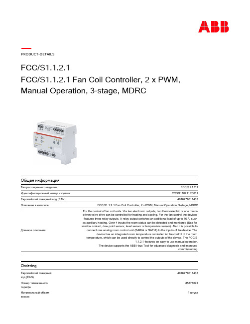
FCC/S1.1.2.1
2CDG110211R0011
4016779011433
FCC/S1.1.2.1 Fan Coil Controller, 2 x PWM, Manual Operation, 3-stage, MDRC
For the control of fan coil units. Via two electronic outputs, two thermoelectric or one motordriven valve drive can be controlled for heating and cooling. For the fan control the devices features three relay outputs. A relay output switches an additional load of up to 16 A, such as auxiliary heating. Over 4 inputs the room status can be detected and monitored (Use for window contact, dew point sensor, level sensor or temperature sensor). Also it is possible to
Environmental
Правила ограничения содержания вредных веществ. RoHS статус
Classifications
ETIM 5
2
405712025 2814557 1739448
63.5 mm 90 mm
105 mm 0.235 kg
Frese ELCO 100 PID 控制器说明书
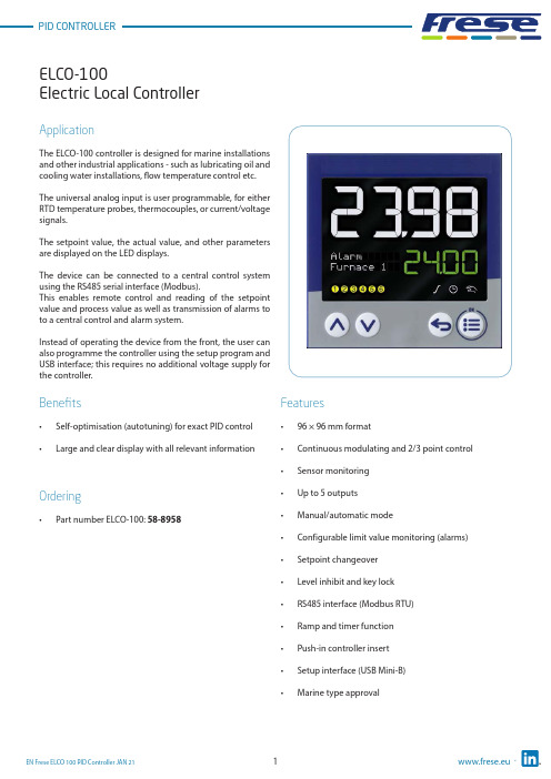
Electric Local ControllerFeatures• 96 × 96 mm format• Continuous modulating and 2/3 point control •Sensor monitoring • Up to 5 outputs • Manual/automatic mode• Configurable limit value monitoring (alarms)• Setpoint changeover • Level inhibit and key lock • RS485 interface (Modbus RTU)• Ramp and timer function • Push-in controller insert • Setup interface (USB Mini-B)•Marine type approvalApplicationThe ELCO-100 controller is designed for marine installations and other industrial applications - such as lubricating oil and cooling water installations, flow temperature control etc.The universal analog input is user programmable, for either RTD temperature probes, thermocouples, or current/voltage signals.The setpoint value, the actual value, and other parameters are displayed on the LED displays.The device can be connected to a central control system using the RS485 serial interface (Modbus).This enables remote control and reading of the setpoint value and process value as well as transmission of alarms to to a central control and alarm system.Instead of operating the device from the front, the user can also programme the controller using the setup program and USB interface; this requires no additional voltage supply for the controller.Benefits• Self-optimisation (autotuning) for exact PID control •Large and clear display with all relevant informationOrdering•Part number ELCO-100: 58-8958Electric Local ControllerFunctional descriptionSelf-optimisation (autotuning)Standard features include the tried and tested self-optimization (oscillation method), which makes it possible for the controller to be matched to the control loop by a user who is not a control technology expert.Here,the reaction of the control path to the specific variable changes is evaluated and the controller parameters proportional band, reset time, derivative time, cycle time, and filter time constant are calculated.Ramp functionThe ramp function is used for a constant change of setpointvalue w up to the ramp limit value SP (entered setpointvalue).A rising or a falling edge arises depending on the actualvalue at the time of ramp start t0.The slope is defined by a gradient which is entered duringthe controller configuration.Limit value monitoringThe controller is equipped with two limit value monitoring functions, each with eight configurable alarm functions. Any analog signals can be selected as actual and setpoint value froma selector. When a limit value is exceeded, a signal can be displayed or an internal controller function initiated. With the limit value monitoring, extensive alarm and limit value functions can be implemented.TimerThe timer is started manually or automatically (after power on, for example). When the timer expires, the timer output signal changes its state (configurable). The timer can be used to implement functions like time-limited control or setpoint changeover.Setup programThe setup program provides the user with an easy and comfortable way to configure the controller using a PC.The PC has to be connected to the controllers USB interface (Mini-B type) with a USB cable.Thereby the controller is powered over the USB interface. As a result, no mains supply is required during the configuration.Electric Local ControllerTechnical data ∙ ELCO-100 ControllerPower consumption: Max. 6.6 WVoltage Supply:AC 110 to 240V, +10/-15 %, 48 to 63HzMeasuring accuracy:≤ 0.1 % of measuring rangeAmbient temperature:-10 °C to 55°CStorage temperature:-30°C to 70°CWeight:220 gProtection class:Acc. to DIN EN 60529 , Front IP65/Rear IP20Dimensions:See drawing next pageOperating position:Any positionL,J,U,T,K,E,N,S,R,B,C,D,A1,L,KAnalog Input:ThermocouplePt100/Pt1000/KTYRTDResistance / Potentiometer (0 to 4000Ω)0(2) to 10V (500kΩ input resistance)0(4) to 20mA (< 2.5V burden voltage)Digital Input:Potential-free contactAnalog Output:0(2)(>500Ωload)10Vto0(4) to 20 mA (<450Ω load)Digital Outputs:Relays (N/O contacts) [Max 3A at AC230V or DC30V, resistive load]Logic output 0/14V (Max output current 20mA)RS485 interface:Modbus RTU (Galvanic isolated)controllerController type:Continousmodulating2/3 point controllerDisplay:Two 18-segment LCD display + Pixel matrix LCD for textUpper display: 25mm Color: White / Lower display: 12mm Color: Green Electrical connection:On the back via spring-cage terminalsApproval: c UL us (UL 61010-1 (3. Ed.), CAN/CSA-22.2 No. 61010-1 (3. Ed.))DNV GL (DNVGL-CG-0339)Alarm:Limit value in relation to setpoint valueFixed limit valueElectric Local ControllerDimensionsDisplay and control elements1. 18-segment LCD display (e.g. actual value), 4-digit2. 18-segment LCD display (e.g. setpoint value), parameters,values and text); display ”OK” when exiting editing mode (with change)3. Activity display for ramp function/program, timer, manualmode4. For type ELCO-100: pixel matrix LCD display for displaying menuitems, parameters and values as well as customer-specific text 5. Switching of the digital outputs (yellow = active)6. Up (in the menu: increase value, select previous menu item orparameter; in basic status: increase setpoint value)7. Down (in menu: reduce value, select next menu item orparameter; in basic status: reduce setpoint value)8. Back (in menu: back to previous menu level, exit editing modewithout change; in basic status: configurable function)9. Menu/OK (call up main menu, switch to submenu/level, switchto editing mode, exit editing mode with change)Electric Local ControllerTechnical dataConnection diagramThe connection diagram in this Technote provides preliminary information about the connection possibilities.For the electrical connection use the operating manual delivered with the product.The knowledge and the correct technical execution of the safety information/instructions contained in these documents are mandatory for installation, electrical connection, and startup as well as for safety during operation.The terminal strips on the device rear are equipped with screw terminals. Please refer to the technical data for specifications concerning the conductor cross section.(1)(2)(3)(4)Electric Local ControllerApplication temperature sensorScrew-in RTD temperature probe for marine applications.Temperature Range from -50 to +400 °CThe RTD temperature probes for standard and marine applications is commonly used for measuring temperatures in liquids and gases in pipes and tanks.Application areas:• Ballast water management • Water treatment systems• Generators, motors, and compressors • Heating and air-conditioning industry • For nearly all applications on shipsBenefits• Quick response times – a reduced probe tip allows response times of t0.9 = 14 s to be reached in water • Increased safety – thanks to successful testing by Bureau Veritas•Flexible and time-saving startup – due to availability of different standardized process connections Features• The connection head is suitable for ambient temperatures up to 100 °C.• Normally fitted with a Pt100 temperature sensor according to DIN EN 60751, Class B in 4-wire circuit connections.•The intelligent design of the RTD temperature probe with a fixed measuring insert allows temperatures to be measured under standard conditions.• Versions of class A or AA are also possible.• Versions with a reduced probe tip are available for quicker response times.• A transmitter can be integrated into the terminal head as an option.•The RTD temperature probes are certified according to Bureau Veritas.Electric Local ControllerTechnical data ∙ RTD temperature sensorTerminal head Form B DIN EN 50446, die-cast aluminum, M20 × 1.5Seal IP65Measuring insert Pt100 temperature sensor DIN EN 60751, cl. B, 4-wire circuit, permanently installed Response times t0.5 = 5 s, t0.9 = 14 s in water 0.4 m/s; ø6 mm Transmitter Accessories Programmable transmitter, output 4 to 20 mA or 20 to 4 mA Operating temperature -50°C to +400°C Measuring insert Protection pocket,Tolerance class Class B (Standard) Class A & AA (Optional)Protection tube Stainless steel 1.4571 (316Ti) in ø6 mm Process connection Screw connection G 1/2 B Environmental influences Admissible temperature at connection head -40°C to +100°C -40°C to +85°C (with transmitter)Permissible torque moment: 130 Nm Permissible flow velocities: Air: 25 m/s Hot steam: 25 m/s Water: 3 m/s Reaction times at liquid velocity = 0.4 m/sec: t 1/2: 5 s t 9/10: 14 s (t = total temperature step) Max. pressure: 165 bar Max. temperature: 400 °C Weight:280 gApprovals/approval marksElectric Local ControllerF rese A/S assumes no responsibility for errors, if any, in catalogues, brochures, and other printed matter. F rese A/S reserves the right to modify its products without prior notice, including already ordered products, if this does not alter existing specifications. All registered trademarks in this material are the property of Frese A/S. All rights reserved.Frese A/STel: +45 58 56 00 00*************Types and Operation DataDimensionsFitting length L: See table below Diameter probe D: ø6 mm Connection thread G:G 1/2 B。
EC100整体机快捷调试手册康达电梯

EC100电梯智能整体机快捷调试手册Ver 1.01.EC100电梯智能整体机端口说明EC100电梯智能整体机端口序号代号名称备注1 CN2 手操器专用连接口与电脑连接时需专用电缆与电脑连接2 CN7 DB62连接口开关量输入/输出,CAN通讯,与I/O 板连接3 CN3 同步主机编码器接口ERN1387或带U、V、W增量编码器4 整体机主回路端子各功率段端子排布主回路端子接线1.1 主回路端子排列5.5kW~15kWEC100电梯智能整体机主回路端子排的布局18.5kW~30kWEC100电梯智能整体机主回路端子排的布局1.2 主回路端子功能描述端子名称功能说明R、S、T 三相电源输入端子(+)、(-) 直流母线正极、负极(+)、PB 制动电阻接线端子U、V、W 三相交流输出端子2.系统安装及布线2.1 井道电气安装在轿顶安装一个平层开关SMDZ。
(有后门时,需要增加后门门区开关),每层安装一块插板,长度200~300 mm。
当轿厢平层时,插板位于平层开关中间位置。
对应不同梯速的电梯,安装了相应数量的强迫减速开关。
1.5m/s以下梯速,安装开关SDS1、SUS1。
1.75m/s~2.0m/s梯速,需加装开关SDS2、SUS2;2.0m/s以上梯速,还需加装开关SDS3、SUS3 (为避免高速运行下的撞击,一般采用双稳态磁开关)。
对于带再平层功能的电梯,在轿顶还须加装上平层开关SUDZ、下平层开关SDDZ。
三个开关按上、中、下垂直安装,SMDZ 居中。
当轿厢准确平层时,插板同时位于三个平层开关位置。
顶层安装一个限位开关SDL、一个极限开关SDFL。
底层安装一个限位开关SUL、一个极限开关SUFL。
2.2 井道开关安装位置图各开关安装距离见下表,开关安装方式请参考井道开关安装位置示意图。
SDS1----低速下强迫减速开关SUS1----低速上强迫减速开关SDS2----中速下强迫减速开关SUS2----中速上强迫减速开关SDS3----高速下强迫减速开关SUS3----高速上强迫减速开关SDL---下限位开关SUL----上限位开关SDFL----下极限开关SUFL----上极限开关井道开关安装位置示意图3. 手持操作器3.1 连接方法操作器的接口与EC100的连接图3.2按键及LED指示灯手持操作器外形及按键定义3.3操作器LED指示灯定义序号标号含义说明1 COM 操作器与EC100 连接通讯指示通讯正常时闪烁2 CAN 操作器与轿厢连接通讯指示通讯正常时闪烁3 PC 操作器与电脑连接通讯指示通讯正常时闪烁4 ALM 电梯故障指示系统检测到故障时亮3.4操作器流程手持操作器菜单操作流程示意图4.慢车运行4.1 线路检查检查下列接线是否按图接线正确。
RS- EC-N01-B工业EC控制器用户手册说明书
RS-EC-N01-B工业EC控制器用户手册文档版本:V1.6目录1.产品介绍 (4)1.1功能特点 (4)1.2设备技术参数 (4)1.3产品选型 (5)1.4产品清单..................................................................................................错误!未定义书签。
1.5设备尺寸 (6)1.6电极尺寸及安装 (6)1.6.1电极类型及尺寸 (6)1.6.2电极安装 (7)2.设备使用说明 (8)2.1接线说明 (8)2.2显示与功能键 (9)2.3菜单结构 (9)3.高低报警设置 (10)4.参数配置说明 (11)4.1ModBus通信及寄存器详解 (11)4.1.1设备通信基本参数 (11)4.1.2数据帧格式定义 (12)4.1.3寄存器地址 (12)4.1.4通讯协议示例以及解释 (12)5.注意事项与维修维护 (14)6.联系方式 (15)7.文档历史 (15)1.产品介绍本产品是我公司研发的电导率控制器,环境适应性强、清晰的显示、简易的操作和优良的测试性能使其具有很高的性价比。
可广泛应用于火电、化工化肥、冶金、环保、制药、生化、食品和自来水等溶液中电导率值的连续监测。
1.1功能特点⏹高智能化:采用高精度AD转换和单片机微处理技术,能完成电导率值和电阻率值测量、温度测量、温度自动补偿等多种功能。
⏹时间显示:EC控制器内置时钟芯片,可以显示当前时间。
⏹数据存储:仪器内置的存储芯片,可以保存过去三天的历史数据,方便用户查找。
⏹冲洗继电器:仪器设置了冲洗继电器,可以通过安装电磁阀定时清洗电极。
⏹25℃折算:对当前温度下的电导率值进行25℃折算,实现了显示25℃时的电导率值,特别适合电厂多种水质的测量。
⏹抗干扰能力强:电流输出采用光电耦合隔离技术,抗干扰能力强,实现远传。
具有良好的电磁兼容性。
风机操作说明
风机操作说明
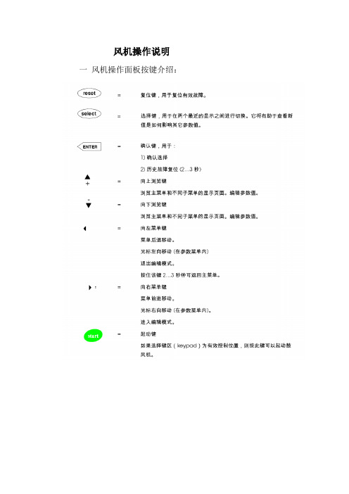
一风机操作面板按键介绍:
二风机菜单介绍:风机共有8个菜单,从M1到M8
M1为监控菜单,可监控风机的运行状态,其内容如下:
M2为参数菜单,用户不需更改。
M3为控制地点菜单,可更改控制地点和设定风量等。
P3.1为控制地点选择,设置KEYPAD为从风机面板启动,设置FIELDBUS为从MCU启动。
P3.3为设定风量,可根据需要更改设定风量。
P3.5为参数锁定,设置25255可解锁,看到M2菜单。
M4为MBC菜单,用户不需更改。
M5为激活故障菜单,用户不需更改。
M6为故障历史菜单,该菜单最多可存储30个故障,可调阅查看。
M7为系统菜单,用户不需更改。
M8为扩展板菜单,用户不需更改。
三风机操作顺序:
1 接通风机主电源和辅助电源。
2合上风机面板上的电源开关。
3 风机面板上会显示F68 AMB FAULT,等待几分钟或按向左菜单键和reset键,直到READY灯亮,并且没有FAULT 或ALARM显示。
4 开启空压机,等到出口压力达到4bar左右。
5 P3.3为设定风量,根据要求设定,设定完后按下START键,风机开始起动,此时可监控风机电流或其他参数,需要停止时按下STOP 键。
6 风机运行时要注意监控风机运行参数。
7如果要停止风机,按下STOP键,风机开始停止。
请等风机完全停止后再关掉风机电源。
8 风机运行时请不要关断主电源和辅助电源。
四风机故障代码如下:。
施乐百EC风机控制器使用说明-2014.7.2

施乐百EC 风机控制器使用说明1.适用范围适用风机适用风机::序号 风机品牌 风机型号 最高转速 额定功率1 施乐百ZIEHL-ABEGG RH63V-ZIK.GL.1R 1340 min -1 3.6kW 2施乐百ZIEHL-ABEGG RH56V-ZIK.GG.1R 1560min -13.1kW适用控制器适用控制器:: 序号项目零件属性品牌图片1 AM-MODBUS 通讯模块 施乐百ZIEHL-ABEGG2 A-G-247NW手持式控制器施乐百ZIEHL-ABEGG2.线路连接2.1安装通讯模块将AM-MODBUS 通讯模块安装于EC 风机控制盒内,安装方式见下图;注意将通讯模块针脚插入风机控制板相应针孔内,并用螺丝将通讯模块固定牢固。
2.2风机风机线路线路线路连接连接施乐百EC 风机强电已由试制组连接好,实验室只需连接弱电控制部分!连接内容如下:打开EC 风机控制盒,将控制板上的24V 端子与D1端子短接(见下图)。
2.3模块线路连接将AM-MODBUS 模块GND 端子、A (D+)端子、B (D-)端子用不同颜色的线引出,并做好标记;保留线的长度与强电线相同,并将线与强电线利落的整理好(见下图)。
2.4模块与手持式控制器连接施乐百EC 风机下沉后,将AM-MODBUS 通讯模块的GDN 端子、A (D+)端子、B (D-)端子与手持式控制器上相应的GDN 端子、A (D+)端子、B (D-)端子连接(见下图)。
注意注意::控制器上无端子标示控制器上无端子标示,,一定按一定按照照下图下图从第二到第四个端子依次连接从第二到第四个端子依次连接GDN 端子端子、、B (D-)端子端子、、A (D+)端子端子。
3手持式控制器手持式控制器的操作的操作将控制器与通讯模块连接后,按照下述步骤操作:a. 按1号键打开控制器电源;(在此之前应先打开风机电源)b. 按7号键出现主界面;c. 按数次2号键直至出现如下界面;此时通讯模块与控制器连接成功;d. 此时按6号键,出现Start ,此时按3号键和4号键可以分别出现Info 、Seeting 、Controller Setup 、IO Setup 等界面;e. 在Start 界面下,按P 键出现PIN input ,输入0010,按P 键确认键确认;;f. 在Controller Setup 下的Controlmode 设置4,按P 键确认键确认;;g.在Seeting 界面下的Set Inern1设置需要的转速设置需要的转速数值数值数值,,按P 见确认见确认;;风机即按数值转速启动。
EC使用说明

答:如果想使用英文的在线客服,需要进行注意以下几点:(1)外观设置中,显示标题要写成英文的,(2)编辑客服身份中,在线留言、离线留言改成英文,(3)客服人员设置——设置客服架构,组名要写成英文
18.EC兼容性如何?
答:EC可绑定QQ,MSN,Skype,雅虎通,淘宝旺旺,还可兼容电话,短信功能,丰富的沟通方式,满足绝大多数客户的沟通需求。
答:访客看到网站客服在线状态(在线或不在线)是访客进入网站那一时刻的EC在线状态,访客要刷新页面才会刷新状态。
2.管理员添加了新员工,新增的那个人也登陆了,为什么网站上不显示?
答:要让员工成为网站上的客服人员,需要进行以下操作:(1)在成员管理中通过新增员工,为员工开通EC账号,(2)在网站客服设置中新增客服人员。
5. EC电话是EC电话客服吗?
答:不是。EC电话是回拨电话,原理是系统先拨主叫号,接通主叫后,系统再拨被叫,被叫接通后,双方就可以进行通话了。此时双方是处于接听的状态,如果双方接听免费的话,只扣系统中电话功能的费用。EC电话客服是400电话。
关于短信
1.为什么我们刚刚充值的短信,发短信却显示余额不足?
答:EC400电话可以帮助企业建立呼叫中心。当有电话呼入时,客服坐席上有弹屏,可监控来电号码,上下班坐席设置,并可实现坐席自动转接,让您不错过任何商机。
2.什么是彩铃模式,什么是总机模式?
答:EC400电话有两种模式,企业在开通时选择一种模式使用:(1)彩铃模式:无语音导航,呼叫方听到的是铃音或录制的语音内容。并且将立即呼转到设置的转接电话上。最多支持16个坐席;(2)总机模式:有语音导航,呼叫方可根据语音导航提示选择所需要服务。按了导航键后,才会转到相应设置的转接电话上。最多支持160个坐席。
FCC S1.3.2.1 风扇机控制器产品说明书
commissioning.
4016779011471 85371091 1 piece
405712225 1739452
FCC/S1.3.2.1
Dimensions
Product Net Depth / Length Product Net Height Product Net Width Product Net Weight
Container Information
Package Level 1 Units Package Level 1 EAN Package Level 1 Depth / Length Package Level 1 Height Package Level 1 Width Package Level 1 Gross Weight
FCC/S1.3.2.1
3
Following EU Directive 2011/65/EU
Classifications
ETIM 5 ETIM 6 ETIM 7 eClass WEEE Category
EC001586 - Heating actuator for bus system EC001586 - Heating actuator for bus system EC001586 - Heating actuator for bus system
Certificates and Declarations (Document Number)
EC反应釜自动控制系统操作说明
XX化学工业有限公司EC反应釜控制系统操作说明书XX科技有限公司2017年02月12日编制目录一、概述 (2)二、操作界面说明 (2)2.1控制柜面板控制按钮说明 (2)2.2上位机电脑终端操作界面按钮说明 (3)三、操作流程 (4)3.1手动档时的控制(1#、2#反应釜一样) (4)3.2手动档时的监控 (5)3.3自动档时的控制(1#、2#反应釜一样) (5)3.4自动档时的监控(1#、2#反应釜一样) (5)3.5搅拌电机 (6)3.6急停按钮 (6)3.7界面帮助 (6)3.8历史记录 (7)3.9、停机 (8)四、注意事项 (8)五、故障分析 (8)六、公司信息 (9)EC反应釜控制系统操作说明一、概述本控制系统的控制使用西门子200PLC控制,性能可靠稳定,维护方便。
本系统的监控使用了人机交互的组态王进行系统的监控,操作简单、直观,易于数据的保存记录,为现场生产提供有效真实的数据,便于提高生产效率及生产分析。
二、操作界面说明本控制系统操控分为两部分控制:一是电控柜控制按钮的控制,二是上位机电脑终端的控制。
2.1控制柜面板控制按钮说明控制柜有6个按钮、一个指示灯:分别为电源灯、电源打开、电源关闭;1#复位、1#急停、2#复位、2#急停。
如图所示:控制柜按钮界面图2.2上位机电脑终端操作界面按钮说明1、在自动控制情况下(点击手动自动切换按钮):1#、2#反应釜分别有——启动、停止两个按钮。
如图所示:自动控制界面图2、在手动控制情况下(点击手动自动切换按钮):1#、2#反应釜分别有——蒸汽调节阀、冷冻水阀、泄压阀、氯乙烷进料阀的启动与停止共8个按钮。
如图所示:手动控制界面图注:反应釜的温度设定值、报警值、上限值,压力设定值、报警值、上限值均可人工设定(点击登录,输入口令登录后,点击所需修改参数后即可修改)。
如图所示:登录界面图三、操作流程接通控制柜外电,合上控制柜内空开F1,此时控制柜面板电源指示灯亮(绿色),控制系统供电正常。
- 1、下载文档前请自行甄别文档内容的完整性,平台不提供额外的编辑、内容补充、找答案等附加服务。
- 2、"仅部分预览"的文档,不可在线预览部分如存在完整性等问题,可反馈申请退款(可完整预览的文档不适用该条件!)。
- 3、如文档侵犯您的权益,请联系客服反馈,我们会尽快为您处理(人工客服工作时间:9:00-18:30)。
施乐百EC 风机控制器使用说明
1.适用范围
适用风机适用风机::
序号 风机品牌 风机型号 最高转速 额定功率
1 施乐百ZIEHL-ABEGG RH63V-ZIK.GL.1R 1340 min -1 3.6kW 2
施乐百ZIEHL-ABEGG RH56V-ZIK.GG.1R 1560min -1
3.1kW
适用控制器适用控制器:: 序号
项目
零件属性
品牌
图片
1 AM-MODBUS 通讯模块 施乐百ZIEHL-ABEGG
2 A-G-247NW
手持式控制
器
施乐百ZIEHL-ABEGG
2.线路连接
2.1安装通讯模块
将AM-MODBUS 通讯模块安装于EC 风机控制盒内,安装方式见下图;注意将通讯模块针脚插入风机控制板相应针孔内,并用螺丝将通讯模块固定牢固。
2.2风机风机线路线路线路连接连接
施乐百EC 风机强电已由试制组连接好,实验室只需连接弱电控制部分!连接内容如下:
打开EC 风机控制盒,将控制板上的24V 端子与D1端子短接(见下图)。
2.3模块线路连接
将AM-MODBUS 模块GND 端子、A (D+)端子、B (D-)端子用不同颜色的线引出,并做好标记;保留线的长度与强电线相同,并将线与强电线利落的整理好(见下图)。
2.4模块与手持式控制器连接
施乐百EC 风机下沉后,将AM-MODBUS 通讯模块的GDN 端子、A (D+)端子、B (D-)端子与手持式控制器上相应的GDN 端子、A (D+)端子、B (D-)端子连接(见下图)。
注意注意::控制器上无端子标示控制器上无端子标示,,一定按一定按照照下图下图从第二到第四个端子依次连接从第二到第四个端子依次连接GDN 端子端子、、B (D-)端子端子、、A (D+)端子端子。
3手持式控制器手持式控制器的操作的操作
将控制器与通讯模块连接后,按照下述步骤操作:
a. 按1号键打开控制器电源;(在此之前应先打开风机电源)
b. 按7号键出现主界面;
c. 按数次2号键直至出现如下界面;此时通讯模块与控制器连接成功;
d. 此时按6号键,出现Start ,此时按3号键和4号键可以分别出现Info 、Seeting 、Controller Setup 、IO Setup 等界面;
e. 在Start 界面下,按P 键出现PIN input ,输入0010,按P 键确认键确认;;
f. 在Controller Setup 下的Controlmode 设置4,按P 键确认键确认;;
g.
在Seeting 界面下的Set Inern1设置需要的转速设置需要的转速数值数值数值,,按P 见确认见确认;;
风机即按数值转速启
动。
4.其他注意事项
两台施乐百风机需要分别控制,将第一台风机转速调至需要值后,将GDN端子线、A (D+)端子线、B(D-)端子线从控制器拔下,再将第二台风机的GDN端子线、A(D+)端
线槽!!
注意线不可插错线槽
子线、B(D-)端子线插入控制器,注意线不可插错
线槽。
