FDFMA2P853中文资料
853资料

050816WebSite In our continuing strategy to deliver unparalleled circuit protection solutions,technical expertise and application leadership, we proudly introduce theWICKMANN Group and its products to the Littelfuse portfolio.VDEM INIA INIATURETURE F USEHOLDERS Holder / No. 852SpecificationsStandardIEC 60127-6UL 512CSA C22.2. No.39ApprovalsVDE Report SEMKOUL Recognized CSA SEVMounting(2) Solder pins 0.5mm x 1.1mm Protection Class & CategoryIP 40 (with Cap 855 acc. to IEC 60529)IP 54 (with Cap 856 acc. to IEC 60529)PC2 (IEC 60127-6)MaterialsHolder/Cap:Black Thermoplastic, UL 94V0Sealing Ring:Silicon (Cap 856)Metal Parts:Copper alloy, corrosion protected Terminals:Solderable, tinned Electrical Data (23ºC)Rated Voltage:250VRated Current: 6.3A (VDE/SEMKO)10A (CSA)12A (UL)Rated Power:2W (VDE)Operating T Operating Temperature emperature -40ºC to +85ºC (consider de-rating)Climatic T Climatic Testest -40ºC/+85ºC/21 days (IEC 60068-2-1...3)Stock Conditions+10ºC to +60ºCrelative humidity ≤ 75% yearly average,without dew, maximum value for 30 days - 95%Vibration Resistance24 cycles at 15 min. each (IEC 60068-2-6)10 - 60Hz at 0.75mm amplitude 60 - 500Hz at 10g acceleration Contact Resistance ≤ 5m ΩImpulse Voltage4 kV, 50 Hz, 1 min., dry Insulation Resistance > 103 M Ω (500 VDC, 1 min.)Solderability235ºC, 2 sec. (Wave)350ºC, 1 sec. (Soldering Iron)Soldering Heat Resistance 350ºC, 5 sec. (IEC 60068-2-20)Minimum Cross Section Conducting path - 0.2mm 2MarkingPart No., 250V, Approvals Unit Weight3.2g (852) / 1.8g (855)3.2g (853) / 1.9g (856)Order InformationP a c k a g i n gBulk (100 pcs.)Order NumbersHolder, IP 40No. 852 0000 100Cap, without Ring, IP 40No. 855 0000 100Holder, IP 54No. 853 0000 100Cap, with Ring, IP 54No. 856 0000 100Cap / No. 855PC Mount, Shocksafe5x20mm FusesCap / No. 856Without silicon ring (IP 40)With silicon ring (IP 54)(from front side only)Vertical / 2-PinHolder / No. 853Specifications are subject to change without noticeNote: 1.00 means the number one with two decimal places. 1,000 means the number one thousand.元器件交易网。
BL8532

安 CE 脚电压-----------------------------------------------------------------------------------------------0.3V~(Vout+0.3)
IFB 脚输入电压 ----------------------------------------------------------------------------------------0.3V~(Vout+0.3)
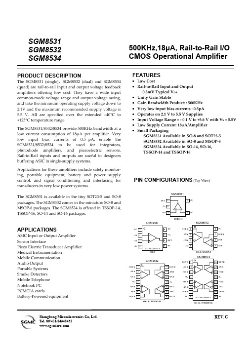
BL8532 提供 SOT-89-5 的封装形式。
• 输出电流精度±10%
• 低输出电流温度漂移:±100ppm/℃
司 • 仅需电感、电容、肖特基二极管、调节
电阻等少量外部元器件
• 效率高达 80%
公
限 用途:
• 给大功率白光 LED 灯提供能源
• 恒流源
有 • 恒压源,用于单、双节电池供电设备的 技 电源部分
典型应用图: (1) 输出恒定电流(恒流源)应用
BL8532
司
(A) 驱动一颗 1W 白光 LED
公
限
有
技
科
安
达 (B) 驱动多串两并小功率白光 LED
众 (2) 输出恒定电压(恒压源)应用
市
圳
深
电路性能介绍
BL8532 是 BOOST 结构、电压型 PFM 控制模式的 DC-DC 转换电路,输出恒定电流或恒定电 压。在恒定输出电流应用情况下外部只需要一个电感、一个输出电容、一个补偿电容、一个肖特基 二极管和一个确定输出电流的电阻就可以提供 0~500mA 的恒定输出电流。在恒定输出电压应用情 况下外部只需要一个电感、一个输出电容、一个肖特基二极管和两个分压电阻、一个补偿电容就可 以提供可调的 2.0V~6.0V 的稳定的低噪声输出电压。芯片内部包括输出电压反馈和修正网络、启动 电路、震荡电路、参考电压电路、PFM 控制电路、过流保护电路、过压保护电路以及功率管。
CXP85390A中文资料

CMOS 8-bit 1-chip MicrocomputerDescriptionThe CXP85300A/85390A are CMOS 8-bit 1-chip microcomputers that serve as both piggyback and evaluator. The CXP85300A/85390A are developed for evaluating the function of the CXP85324A/CXP 85332A/85340A.Note that CXP85300A corresponds to the fixed font, and CXP85390A corresponds to the custom font respectively.Features •Instruction set which supports a wide array of data types—213 types of instructions which include 16-bit calculations, multiplication and division arithmetic,and boolean bit operations.•Minimum instruction cycle 1µs/4MHz (4MHz version)0.5µs/8MHz (8MHz version)•EPROM 27C512LCC type 27C512• Incorporated RAM capacity 576 bytes •EPROM for custom font (CXP85390A only)LCC type 27C256, LCC type 27C512(used volume is 16K bytes)•Peripheral functions— On-screen display function 12 ×18 dots, 256 types 15 colors, 21 characters ×12 linesBlack frame output half blanking, shadow, background color on full screen/half blankingDouble scanning mode, jitter elimination circuit— I 2C bus interface — PWM output 14 bits, 1 channel8 bits, 8 channels— Remote control receiving circuit 8-bit pulse measurement counter, 6-stage FIFO — A/D converter 8 bits, 4 channels, successive approximation system(conversion time of 40µs/4MHz, 8MHz)— HSYNC counter— Power supply frequency counter — Watchdog timer — Serial I/O 8-bit clock synchronized — Timers 8-bit timer, 8-bit timer/counter, 19-bit time-base timer •Interrupts 14 factors, 14 vectors multi-interruption possible •Standby mode Sleep •Package 64-pin ceramic SDIP/QFP StructureSilicon gate CMOS ICNote) Optional mask depends on the type of the CXP85300A/85390A. Refer to the product list for details.– 1–E94334A7Z-PSSony reserves the right to change products and specifications without prior notice. This information does not convey any license by any implication or otherwise under any patents or other right. Application circuits shown, if any, are typical examples illustrating the operation of the devices. Sony cannot assume responsibility for any problems arising out of the use of these circuits.CXP85300A/85390A64 pin PSDIP (Ceramic)64 pin PSDIP (Ceramic)64 pin PQFP (Ceramic)Piggyback/evaluator typePurchase of Sony's I 2C components conveys a license under the Philips I 2C Patent Rights to use these components in an I 2C system, provided that the system conforms to the I 2C Standard Specifications as defined by Philips.V DD NC V SS MP PF0/PWM0PF1/PWM1PF2/PWM2PF3/PWM3YM YS I B G R EXLC XLC PE0/INT0PE1/INT1PE2/AN0PE3/AN1PE4/AN2PE5/AN3PE6/PWM PE7/TO RST EXTAL XTAL PD0/INT2PF4/PWM4/SCL0PF5/PWM5/SCL1PF6/PWM6/SDA0PF7/PWM7/SDA1Note)1. NC (Pin 63) is always connected to V DD .2. Vss (Pins 32 and 62) are always connected to GND.3. MP (Pin 61) is always connected to GND.– 2–Pin Assignment: Piggyback mode 1(Top View) 64 pin PSDIP PackagePF3/PWM3YM YS I B G R EXLCPF4/PWM4/SCL0PF5/PWM5/SCL1PF6/PWM6/SDA0PF7/PWM7/SDA1A 2A 3A 4A 5A 7/H S Y N CS SA 6/V S Y N CD DCPF 0/P W M 0F 2/P W M 2F 1/P W M 1P D 6/R M CP D 5/A C IP D 4/H S IP D 3/S IP D 1/S C KV S SP D 2/S OP D 0/I N T 2X T A LE X T A LR S TP E 6/P W MP E 7/T OXLC PE0/INT0PE1/INT1PE2/AN0PE3/AN1PE4/AN2PE5/AN3Note)1. NC (Pin 56) is always connected to V DD .2. Vss (Pins 26 and 58) are always connected to GND.3. MP (Pin 55) is always connected to GND.– 3–Pin Assignment: Piggyback mode 2(Top View) 64 pin PQFP Package– 4–V DD NC V SS MP PF0/PWM0PF1/PWM1PF2/PWM2PF3/PWM3YM YS I B G R EXLC XLC PE0/INT0PE1/INT1PE2/AN0PE3/AN1PE4/AN2PE5/AN3PE6/PWM PE7/TO RST EXTAL XTAL PD0/INT2PF4/PWM4/SCL0PF5/PWM5/SCL1PF6/PWM6/SDA0PF7/PWM7/SDA1Note)1. NC (Pin 63) is always connected to V DD .2. Vss (Pins 32 and 62) are always connected to GND.3. MP (Pin 61) is always connected to GND.Pin Assignment: Evaluator Mode 1(Top View) 64 pin PSDIP Package– 5–PF3/PWM3YM YS I B G R EXLCPF4/PWM4/SCL0PF5/PWM5/SCL1PF6/PWM6/SDA0PF7/PWM7/SDA1PB7PB6PB5PB4PB3PB2PB1PB0PC7PC6PC5PC4PC3PC2PC1PC0PD7/ECA 2A 3A 4A 5A 7/H S Y N CS SA 6/V S Y N CD DCPF 0/P W M 0F 2/P W M 2F 1/P W M 1PA1PA0P D 6/R M CP D 5/A C IP D 4/H S IP D 3/S IP D 1/S C KV S SP D 2/S OP D 0/I N T 2X T A LE X T A LR S TP E 6/P W MP E 7/T OXLC PE0/INT0PE1/INT1PE2/AN0PE3/AN1PE4/AN2PE5/AN3Note)1. NC (Pin 56) is always connected to V DD .2. Vss (Pins 26 and 58) are always connected to GND.3. MP (Pin 55) is always connected to GND.Pin Assignment: Evaluator Mode 2(Top View) 64 pin PQFP Package– 6–Pin Assignment: Piggyback ModeV DD NC V SS MP PF0/PWM0PF1/PWM1PF2/PWM2PF3/PWM3YM YS I B G R EXLC XLC PE0/INT0PE1/INT1PE2/AN0PE3/AN1PE4/AN2PE5/AN3PE6/PWM PE7/TO RST EXTAL XTAL PD0/INT2PF4/PWM4/SCL0PF5/PWM5/SCL1PF6/PWM6/SDA0PF7/PWM7/SDA1Note)1. NC (Pin 63) is always connected to V DD .2. Vss (Pins 32 and 62) are always connected to GND.3. MP (Pin 61) is always connected to GND.– 7–Pin Assignment: Evaluator ModeV DD NC V SS MP PF0/PWM0PF1/PWM1PF2/PWM2PF3/PWM3YM YS I B G R EXLC XLC PE0/INT0PE1/INT1PE2/AN0PE3/AN1PE4/AN2PE5/AN3PE6/PWM PE7/TO RST EXTAL XTAL PD0/INT2PF4/PWM4/SCL0PF5/PWM5/SCL1PF6/PWM6/SDA0PF7/PWM7/SDA1Note)1. NC (Pin 63) is always connected to V DD .2. Vss (Pins 32 and 62) are always connected to GND.3. MP (Pin 61) is always connected to GND.– 8–ItemAddress →data input delay time Address →data hold timeSymbolt ACC t IHPin A0 to A15D0 to D7A0 to A15D0 to D7Min.0Max.150∗1250∗2Unit ns nsEPROM Read Timing(Ta = –20 to +75°C, V DD = 4.5 to 5.5V, V SS = 0V)Product ListOptional itemPackage 64 pin plastic SDIP/QFP64 pin ceramic PSDIP/PQFP4MHzEPROM 40K bytesExistent ExistentFixedEPROM 16K bytes64 pin ceramic PSDIP Oscillator clockROM capacity Reset pinpull-up resister Power-on reset circuit Font dataProductPiggyback/evaluatorCXP85300A-U02S CXP85300A-U02Q CXP85390A-U02S CXP85390A-U03SCXP85300A-U03SCXP85300A-U03QCXP85324A CXP85332A CXP85340AMask24K bytes 32K bytes 40K bytes Existent/Non existent Existent/Non existentUser data4MHz/8MHz∗1Oscillator clock 8MHz version ∗2Oscillator clock 4MHz version8MHz4MHz8MHzPiggyback mode/evaluator mode switching process is as follows.LCC type EPROMPiggyback modeDIP type EPROM– 9–Piggyback mode/evaluator mode switching process is as follows.Two EPROMs forcustom font(Both have thesame contens.)LCC type EPROM CXP85390A CPU probePiggyback modePin 1 markNote)The evaluator mode capshould be connected tothe CPU probe.– 10–– 11–Package Outline Unit: mmSONY CODE EIAJ CODEJEDEC CODEPACKAGE STRUCTUREPACKAGE MATERIALLEAD TREATMENT LEAD MATERIAL PACKAGE WEIGHTCERAMIC GOLD PLATING 42 ALLOY 0.46 ± 0.08 1.778 ± 0.10.91.27 ± 0.253.43 ± 0.389.8 M A XPSDIP-64C-01ADIP064-C-0750-A64PIN PSDIP (CERAMIC) 750mil16.0g– 12–SONY CODE EIAJ CODE JEDEC CODEPACKAGE STRUCTUREPACKAGE MATERIALLEAD TREATMENT LEAD MATERIAL PACKAGE WEIGHTCERAMIC GOLD PLATING 42 ALLOY PSDIP-64C-02ADIP064-C-0750-B0.90.46 ± 0.08 1.778 ± 0.11.27 ± 0.253.43 ± 0.3811.24 M A X19.05 ± 0.250.25 – 0.02+ 0.0564PIN PSDIP (CERAMIC)22.8g。
AZ853中文资料

GENERAL DATALife ExpectancyMinimum operations Mechanical 1 x 10⁸at 3HzElectrical 1 x 10⁵at 0.5 A, 125 VAC, Res.2 x 105at 1.0 A, 30 VDC, Res.Operate Time3 ms at nominal coil voltage (typical)Release Time (typical) 3 ms at nominal coil voltage (with no coil suppression)Bounce (typical)At 10 mA contact current 1 ms at operate or releaseCapacitance < 1 pF at 10 KHz—open contacts< 1 pF at 10 KHz—adjacent contact sets Dielectric Strength See table(at sea level)DropoutGreater than 10% of nominal coil voltage Insulation Resistance109ohms min. at 25°C, 500 VDC,50% RHAmbient TemperatureAt nominal coil voltageOperating -40°C (-40°F) to 85°C (185°F)Storage-40°C (-40°F) to 115°C (239°F)Vibration Operational, 20 g, 10–55 Hz Non-destructive, 30 g, 10–55 Hz ShockOperational, 50 g min., 11 msNon-destructive, 100 g min., 11 ms Max. Solder Temp.350°C (662°F) for 3 seconds Temp./Time 260°C (500°F) for 10 seconds Max. Solvent Temp.80°C (176°F) Max. Immersion Time 30 seconds Weight 1.0 grams Enclosure P.B.T. polyesterTerminalsTinned copper alloy, P.C.POLARIZED RELAYFEATURES•Conforms to IEC60950/UL1950/EN60950 spacing and high breakdown voltageClearance: 1.0 mm (between coil and contacts)Creepage: 1.6 mm (between coil and contacts)Basic Insulation: 150 V Working Voltage, Pollution Degree 2•Monostable and bistable (latching) versions available •High dielectric and surge voltage:2.5 KV surge (per Bellcore TA–NWT–001089)1.5 KV surge (per FCC Part 68)1,000 Vrms, open contacts•Low power consumption: 79 mW pickup•Stable contact resistance for low level signal switching •Epoxy sealed for automatic wave soldering and cleaning •UL file E43203; CSA file 212940•All plastics meet UL94 V–0, 30 min. oxygen index CONTACTSArrangement DPDT (2 Form C)Bifurcated crossbar contacts RatingsResistive load:Max. switched power:60 W or 62.5 VA Max. switched current:2.0 AMax. switched voltage:220 VDC or 250 VACRated Load UL/CSA0.5 A at 125VAC 2.0 A at 30VDC 0.3 A at 110VDC Material Silver alloy; gold cladResistance< 75 milliohms initially at 6 V, 1 ACOIL (Polarized)PowerAt Pickup Voltage 79 mW (3–12 VDC)(typical)130 mW (24 VDC)Max. Continuous 1.0 W at 20°C (68°F) Dissipation 0.78 W at 40°C (104°F) Temperature RiseAt nominal coil voltage 18°C (32°F) (3–12 VDC)25°C (45°F) (24 VDC)TemperatureMax. 115°C (239°F)NOTES1.All values at 20°C (68°F).2.Relay may pull in with less than “Must Operate” value.3.Relay has fixed coil polarity.4.Specifications subject to change without notice.RELAY ORDERING DATANON-LATCHING VERSIONNominal CoilMax. ContinuousCoil ResistanceMust OperateORDER NUMBERVDC VDC ± 10%VDC THT SMT *SMTss *1.52.2516.11.13AZ853–1.5AZ853S–1.5AZ853S1–1.53 4.564.3 2.25AZ853–3AZ853S–3AZ853S1–34.5 6.75145 3.38AZ853–4.5AZ853S–4.5AZ853S1–4.569257 4.5AZ853–6AZ853S–6AZ853S1–6913.5579 6.75AZ853–9AZ853S–9AZ853S1–9121810289.00AZ853–12AZ853S–12AZ853S1–122436250418.00AZ853–24AZ853S–24AZ853S1–24LATCHING VERSIONNominal CoilMax. ContinuousCoil ResistanceMust OperateORDER NUMBERVDC VDC ± 10%VDC THTSMT *SMTss *1.52.2522.51.13AZ853P–1.5AZ853PS–1.5AZ853PS1–1.53 4.590 2.25AZ853P–3AZ853PS–3AZ853PS1–34.5 6.75203 3.38AZ853P–4.5AZ853PS–4.5AZ853PS1–4.569360 4.50AZ853P–6AZ853PS–6AZ853PS1–6913.5810 6.75AZ853P–9AZ853PS–9AZ853PS1–9121814409.00AZ853P–12AZ853PS–12AZ853PS1–122436480018.00AZ853P–24AZ853PS–24AZ853PS1–24*Tape and reel available (1K pcs/reel minimum)INITIAL DIELECTRIC STRENGTH (minimum)SURGEVRMS, 1 min.Peak (V)Rise Time (µS)Decay Time*(9µS)(1/2peak)Between open contacts 1,0001,50010160Between contact sets 1,0001,5002160Between coil and contacts1,5002,500210* Decay time measured from beginning of surge.Temperature Profile Packaging SpecificationsPackagingOrientation mark sideFeedingReel dimensionsTop cover tapeEmbossed carrier tapeTape DimensionsUnit: mmGeneral tolerance is ± 0.2。
SGM8531中文资料
SGM8531 SGM8532 SGM8534PRODUCT DESCRIPTIONThe SGM8531 (single),SGM8532 (dual) and SGM8534 (quad) are rail-to-rail input and output voltage feedback amplifiers offering low cost. They have a wide input common-mode voltage range and output voltage swing, and take the minimum operating supply voltage down to 2.1V and the maximum recommended supply voltage is 5.5 V. All are specified over the extended –40°C to +125°C temperature range.The SGM8531/8532/8534 provide 500KHz bandwidth at a low current consumption of 18µA per amplifier. Very low input bias currents of 0.5pA, enable the SGM8531/8532/8534 to be used for integrators, photodiode amplifiers, and piezoelectric sensors. Rail-to-Rail inputs and outputs are useful to designers buffering ASIC in single-supply systems.Applications for these amplifiers include safety monitor- ing, portable equipment, battery and power supply control, and signal conditioning and interfacing for transducers in very low power systems.The SGM8531 is available in the tiny SOT23-5 and SO-8 packages. The SGM8532 comes in the miniature SO-8 and MSOP-8 packages. The SGM8534 is offered in TSSOP-14, TSSOP-16, SO-14 and SO-16 packages.APPLICATIONSASIC Input or Output Amplifier Sensor InterfacePiezo Electric Transducer Amplifier Medical Instrumentation Mobile Communication Audio Output Portable Systems Smoke Detectors Mobile Telephone Notebook PC PCMCIA cardsBattery-Powered equipment500KHz,18µA, Rail-to-Rail I/O CMOS Operational AmplifierFEATURES• Low Cost• Rail-to-Rail Input and Output0.8mV Typical V OS • Unity Gain Stable• Gain Bandwidth Product: : 500KHz • Very low input bias currents : 0.5pA • Operates on 2.1 V to 5.5 V Supplies• Input Voltage Range = - 0.1 V to +5.6 V with V S = 5.5V • Low Supply Current: 18µA/Amplifier • Small PackagingSGM8531 Available in SO-8 and SOT23-5 SGM8532 Available in SO-8 and MSOP-8 SGM8534 Available in SO-14, SO-16, TSSOP-14 and TSSOP-16PIN CONFIGURATIONS (Top View)S NC-V NC OUT S-V SOT23-5OUT B S -V SO-8 / MSOP-8OUT -IN A +IN A S +V -IN DD SO-16 / TSSOP-16-INB +IN B -IN C NCOUT BOUT C C D OUT +V -IN B +INB OUT BS -IN D+IN D -IN C OUT C+IN C OUT DShengbang Microelectronics Co, Ltd REV . CELECTRICAL CHARACTERISTICS : V S = +5V (At R L = 200kΩ connected to Vs/2 and V OUT = Vs/2, unless otherwise noted)Specifications subject to change without notice.PACKAGE/ORDERING INFORMATIONMODEL ORDER NUMBER PACKAGEDESCRIPTIONPACKAGE OPTION MARKING INFORMATIONSGM8531XN5/TRSOT23-5Tape and Reel, 30008531 SGM8531SGM8531XS/TR SO-8 Tape and Reel, 2500 SGM8531XS SGM8532XS/TR SO-8 Tape and Reel, 2500 SGM8532XS SGM8532SGM8532XMS/TRMSOP-8Tape and Reel, 3000SGM8532XMS SGM8534XS/TR SO-16 Tape and Reel, 2500SGM8534XSSGM8534XS14 SO-14Tube SGM8534XS14SGM8534XTS/TR TSSOP-16 Tape and Reel, 3000 SGM8534XTSSGM8534SGM8534XTS14 TSSOP-14TubeSGM8534XTS14ABSOLUTE MAXIMUM RATINGSSupply Voltage, V+ to V- ........................................... 7.5 VCommon-Mode Input Voltage.......................................... (–V S ) – 0.5 V to (+V S )+0.5VStorage Temperature Range.................. –65℃ to+150℃ Junction Temperature ................................................160℃ Operating Temperature Range ............ –55℃ to +150℃Package Thermal Resistance @ T A = 25℃SOT23-5, θJA .............................................................. 190/W ℃ SO-8, θJA ......................................................................125/W ℃ MSOP-8, θJA .............................................................. 216/W ℃ SO-16, θJA ..................................................................... 82/℃W TSSOP-16, θJA ............................................................ 105/W ℃ Lead Temperature Range (Soldering 10 sec).....................................................260℃ESD SusceptibilityHBM................................................................................4000V MM (400V)NOTES1. Stresses above those listed under Absolute Maximum Ratings may cause permanent damage to the device. This is a stress rating only; functional operation of the device at these or any other conditions above those indicated in the operational section of this specification is not implied. Exposure to absolute maximum rating conditions for extended periods may affect device reliability.CAUTIONThis integrated circuit can be damaged by ESD. Shengbang Micro-electronics recommends that all integrated circuits be handled with appropriate precautions. Failure to observe proper handling and installation procedures can cause damage.ESD damage can range from subtle performance degradation to complete device failure. Precision integrated circuits may be more susceptible to damage because very small parametric changes could cause the device not to meet its published specifications.TYPICAL PERFORMANCE CHARACTERISTICSAt T A = +25℃, V S = +5V , and R L =200k Ω connected to Vs/2,unless otherwise noted.Small-Signal Step Response Small-Signal Step Response10µs/div 10µs/divG = +1C L = 100pF R L = 5K ΩG = +1 C L = 100pF R L= 200K ΩG = +1 C L = 100pF R L= 200K Ω20m V /d i v50m V /d i v500m V /d i vLarge-Signal Step Response20µs/divTYPICAL PERFORMANCE CHARACTERISTICS At T A= +25℃, V S = +5V, and R L=200kΩ connected to Vs/2,unless otherwise noted.TYPICAL PERFORMANCE CHARACTERISTICSAt T A = +25℃, V S = +5V , and R L =200k Ω connected to Vs/2,unless otherwise noted.2.5V0V 250mV0VVs = 5V G = -10 V IN = 250mVTime(20μs/div)Overload Recovery TimeAPPLICATION NOTESDriving Capacitive LoadsThe SGM853X can directly drive 250pF in unity-gain without oscillation. The unity-gain follower (buffer) is the most sensitive configuration to capacitive loading. Direct capacitive loading reduces the phase margin of amplifiers and this results in ringing or even oscillation. Applications that require greater capacitive drive capability should use an isolation resistor between the output and the capacitive load like the circuit in Figure 1. The isolation resistor R ISO and the load capacitor C L form a zero to increase stability. The bigger the R ISO resistor value, the more stable V OUT will be. Note that this method results in a loss of gain accuracy because R ISO forms a voltage divider with the R LOAD.V IN V OUTFigure 1. Indirectly Driving Heavy Capacitive LoadAn improvement circuit is shown in Figure 2, It provides DC accuracy as well as AC stability. R F provides the DC accuracy by connecting the inverting signal with the output, C F and R Iso serve to counteract the loss of phase margin by feeding the high frequency component of the output signal back to the amplifier’s inverting input, thereby preserving phase margin in the overall feedback loop.V IN V OUTFigure 2. Indirectly Driving Heavy Capacitive Load with DC AccuracyFor no-buffer configuration, there are two others ways to increase the phase margin: (a) by increasing the amplifier’s gain or (b) by placing a capacitor in parallel with the feedback resistor to counteract the parasitic capacitance associated with inverting node. Power-Supply Bypassing and Layout The SGM853X family operates from either a single +2.5V to +5.5V supply or dual ±1.25V to ±2.75V supplies. For single-supply operation, bypass the power supply V DD with a 0.1µF ceramic capacitor which should be placed close to the V DD pin. For dual-supply operation, both the V DD and the V SS supplies should be bypassed to ground with separate 0.1µF ceramic capacitors. 2.2µF tantalum capacitor can be added for better performance.VnVpV SSV SS(GND)Figure 3. Amplifier with Bypass CapacitorsTypical Application Circuits Differential AmplifierThe circuit shown in Figure 4 performs the difference function. If the resistors ratios are equal ( R4 / R3 = R2 / R1 ), thenV OUT = ( Vp – Vn ) × R2 / R1 + Vref.Vn VpOUT Figure 4. Differential AmplifierInstrumentation AmplifierThe circuit in Figure 5 performs the same function as that in Figure 4 but with the high input impedance.Vn VpV OUT Figure 5. Instrumentation AmplifierLow Pass Active FilterThe low pass filter shown in Figure 6 has a DC gain of ( - R2 / R1 ) and the –3dB corner frequency is 1/2πR2C. Make sure the filter is within the bandwidth of the amplifier. The Large values of feedback resistors can couple with parasitic capacitance and cause undesired effects such as ringing or oscillation in high-speed amplifiers. Keep resistors value as low as possible and consistent with output loading consideration.V INV OUT Figure 6. Low Pass Active FilterPACKAGE OUTLINE DIMENSIONS SOT23-5PACKAGE OUTLINE DIMENSIONS SO-8PACKAGE OUTLINE DIMENSIONS MSOP-8PACKAGE OUTLINE DIMENSIONS SO-16PACKAGE OUTLINE DIMENSIONS TSSOP-16PACKAGE OUTLINE DIMENSIONS SO-14PACKAGE OUTLINE DIMENSIONS TSSOP-14REVISION HISTORYLocation Page 11/06— Data Sheet changed from REV.A to REV.BChanges to ABSOLUTE MAXIMUM ATINGS . . . . . . . . . . . . . . . . . . . . . . . . . . . . . . . .. . . . . . . . . . . . . . . . . . . . . . . . . . .. . . . . . . 3 05/07— Data Sheet changed from REV.B to REV.CAdds SO-14 and TSSOP-14 Package . . . . . . . . . . . . . . . . . . . . . . . . . . . . . . . . . . . . . . . . . . . . . . . .. . . . . . . . . . . . . . . . .. 1,3,14,15Shengbang Microelectronics Co, LtdUnit 3, ChuangYe PlazaNo.5, TaiHu Northern Street, YingBin Road Centralized Industrial ParkHarbin Development ZoneHarbin, HeiLongJiang 150078P.R. ChinaTel.: 86-451-84348461Fax: 86-451-84308461。
PDF33M0125P5DN 产品说明书
Eaton PDF33M0125P5DNPower Defense Globally Rated 100% UL, Frame 3, Three Pole, 125A, 65kA/480V, PXR25 ARMS LSIG w/ Modbus RTU, CAM Link and Relays, No TerminalsEaton Power Defense molded case circuit breakerPDF33M0125P5DN 786679528105109.1 mm 257.1 mm 138.9 mm 5.92 kg Eaton Selling Policy 25-000, one (1) year from the date of installation of theProduct or eighteen (18) months from thedate of shipment of the Product,whichever occurs first.RoHS Compliant IEC 60947-2CCC MarkedProduct NameCatalog Number UPCProduct Length/Depth Product Height Product Width Product Weight WarrantyCompliancesCertificationsModbus / Relays / CAM65 kAIC at 480 Vac3690125 AThree-pole600 VPD3 Global (100% UL)22 kAIC Icu @250 Vdc100 kAIC @240V (UL)35 kAIC @600V (UL/CSA)50 kAIC Icu/ 40 kAIC Ics/ 105 kAIC Icm @440V (IEC)70 kAIC Icu/ 53 kAIC Ics/ 154 kAIC Icm @380-415V (IEC)50 kAIC Icu/ 30 kAIC Ics/ 105 kAIC Icm @480V Brazil (IEC)100 kAIC Icu/ 100 kAIC Ics/ 220 kAIC Icm @240V (IEC)15 kAIC Icu/ 7.5 kAIC Ics/ 31.5 kAIC Icm @690V (IEC)30 kAIC Icu/ 15 kAIC Ics/ 63 kAIC Icm @525V South Africa (IEC) 65 kAIC @480V (UL)ElectronicClass AComplete breakerNo Terminals600 Vac Eaton Power Defense MCCB PDF33M0125P5DN 3D drawingConsulting application guide - molded case circuit breakersPower Xpert Protection Manager x32Power Xpert Protection Manager x64StrandAble terminals product aidPower Defense technical selling bookletPower Defense brochurePower Defense molded case circuit breaker selection posterMolded case circuit breakers catalogPower Xpert Release trip units for Power Defense molded case circuit breakersPDG3 UL authorization 250-600a TMTUPower Defense Declaration concerning California’s Proposition 65 PDG3 UL authorization 100-400aPower Defense Frame 3 Breaker Instructions (IL012107EN).pdfPower Defense Frame 5 Trip Unit How-To VideoPower Defense Frame 6 Trip Unit How-To VideoPower Defense Frame 3 Variable Depth Rotary Handle Mechanism Installation How-To VideoPower Defense BreakersEaton Power Defense for superior arc flash safetyPower Defense Frame 2 Variable Depth Rotary Handle Mechanism Installation How-To VideoPower Defense molded case circuit breakersEaton Specification Sheet - PDF33M0125P5DNPower Defense time current curve Frame 3 - PD3Special featuresInterrupt ratingFrameRated operation voltage (Ue) at AC - max Amperage RatingNumber of polesVoltage rating - maxCircuit breaker typeInterrupt rating rangeSwitch off techniqueClassCircuit breaker frame typeTerminalsVoltage rating 3D CAD drawing package Application notesBrochuresCatalogsCertification reportsInstallation instructions MultimediaSpecifications and datasheets Time/current curves Warranty guidesEaton Corporation plc Eaton House30 Pembroke Road Dublin 4, Ireland © 2023 Eaton. All Rights Reserved. Eaton is a registered trademark.All other trademarks areproperty of their respectiveowners./socialmediaPXR 25 LSIG w/ARMS Modbus RTU and CAM Link Selling Policy 25-000 - Distribution and Control Products and ServicesMaking a better machineMolded case and low-voltage power circuit breaker healthIntelligent circuit protection yields space savingsImplementation of arc flash mitigating solutions at industrial manufacturing facilitiesIntelligent power starts with accurate, actionable dataSafer by design: arc energy reduction techniquesMolded case and low-voltage breaker healthTrip TypeCommunicationWhite papers。
PCF8535中文资料

PCF8535
Bias system Set bias system Temperature measurement Temperature read back Temperature compensation Temperature coefficients VOP Set VOP value Voltage multiplier control S[1:0] Addressing Input addressing Output addressing Instruction set RAM read/write command page Function and RAM command page Display setting command page HV-gen command page Special feature command page Instruction set I2C-bus interface Characteristics of the I2C-bus I2C-bus protocol LIMITING VALUES (PROVISIONAL) HANDLING DC CHARACTERISTICS AC CHARACTERISTICS RESET TIMING APPLICATION INFORMATION BONDING PAD LOCATIONS DEVICE PROTECTION DIAGRAM TRAY INFORMATION DEFINITIONS LIFE SUPPORT APPLICATIONS PURCHASE OF PHILIPS I2C COMPONENTS BARE DIE DISCLAIMER
• Automotive information systems • Telecommunication systems • Point-of-sale terminals • Instrumentation. 3 GENERAL DESCRIPTION
AD8532资料
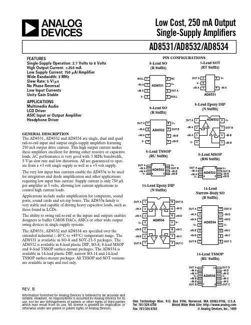
a
FEATURES Single-Supply Operation: 2.7 Volts to 6 Volts High Output Current: ؎ 250 mA Low Supply Current: 750 A/Amplifier Wide Bandwidth: 3 MHz Slew Rate: 5 V/ s No Phase Reversal Low Input Currents Unity Gain Stable APPLICATIONS Multimedia Audio LCD Driver ASIC Input or Output Amplifier Headphone Driver
8-Lead TSSOP (RU Suffix)
OUT A –IN A +IN A V– 1 8 V+ OUT B –IN B +IN B OUT A –IN A +IN A V–
8-Lead MSOP (RM Suffix)
1 8 V+ OUT B –IN B +IN B
AD8532
4 5
AD8532
Specifications subject to change without notice.
S
= +3.0 V, VCM = 1.5 V, TA = +25؇C unless otherwise noted)
Conditions Min Typ Max 25 30 50 60 25 30 3 Unit mV mV pA pA pA pA V dB V/mV µV/°C fA/ °C fA/ °C V V mV mV mA Ω dB mA mA V/µs µs MHz Degrees dB nV/√Hz nV/√Hz pA/√Hz
MAA50-2K481515SBP中文资料
Switching on standart diagram
~In (L) ~In (N)
ground
FUin
~In (L) ~In (N)
+Out
Power module
Case
-Out
Сout1 Сout2
Rheat
FUin – current safety device 1A for input voltage 220VAC, 2A for input voltage 115VAC. Sout – ceramic condenser capacity 0,47-15 mcF with corresponding operating voltage to decrease high-frequency noise level. Sout2 – electronic condenser capacity 22-100 mcF in consideration with operating voltage and polarity. It makes for purpose to decrease
tel/fax +420-266-107-609
元器件交易网
Switching Power Supplies МАА Series MAA50
Output settings
№ pin Single-channel Dual-channel Triple-channel
1 case case case
Uout1 less than 20%
Output 2 and 3 multi-output execution (Inom 10 – 100%)
±13
Uout2&3 differs from
SC6531平台替代料_替代方案_汇总_1306
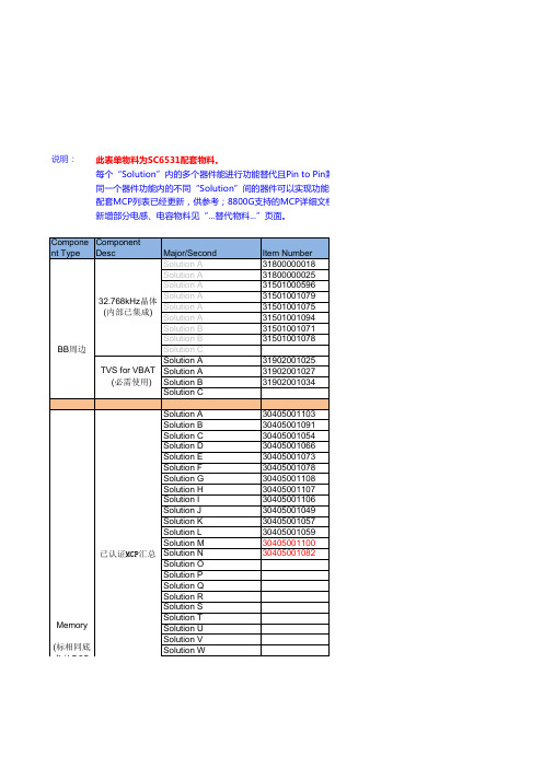
说明:
新增部分电感、电容物料见“…替代物料...”页面。
此表单物料为SC6531配套物料。
S
每个“Solution”内的多个器件能进行功能替代且Pin to Pin兼容同一个器件功能内的不同“Solution”间的器件可以实现功能替配套MCP列表已经更新,供参考;8800G支持的MCP详细文档。
兼容,未标颜色底色的各Solution 不包括)
(标相同底色的PCB
电路主料
并行接口
方案1
SC6531平台替代料_替代方案汇总单 1306 in兼容,为2nd source。
功能替代,但性能可能有差异或不是Pin to Pin兼容。
文档。
另有RF方案的文档附件。
使用经认证Sensor芯片、连接器接口信号与BB匹配即可。
MA2J732 (MA732) 肖特基二极管数据表说明书

Schottky Barrier Diodes (SBD)MA2J732 (MA732)Silicon epitaxial planar typeFor switchingFor wave detection I Features•Low forward voltage V F , optimum for low voltage rectification •Low V F type of MA3X704A (MA704A)•Optimum for high frequency rectification because of its short re-verse recovery time (t rr )•S-Mini type 2-pin packageI Absolute Maximum Ratings T a = 25°CParameterSymbol Rating Unit Reverse voltage (DC)V R 30V Peak reverse voltage V RM 30V Peak forward current I FM 150mA Forward current (DC)I F 30mA Junction temperature T j 125°C Storage temperatureT stg−55 to +125°CMarking Symbol: 2CParameterSymbol ConditionsMinTypMax Unit Reverse current (DC)I R V R = 30 V 30µA Forward voltage (DC)V F1I F = 1 mA 0.3VV F2I F = 30 mA 1.0Terminal capacitance C t V R = 1 V, f = 1 MHz 1.5pF Reverse recovery time *t rr I F = I R = 10 mA1.0ns I rr = 1 mA, R L = 100 ΩDetection efficiencyηV in = 3 V (peak) , f = 30 MHz 65%R L = 3.9 k Ω, C L = 10 pFI Electrical Characteristics T a = 25°CBias Application Unit N-50BU90%Pulse Generator (PG-10N)R s = 50 10%Input PulseOutput Pulset r t pt rrV I FttAUnit: mm1 : Anode2 : Cathode EIAJ : SC-90ASMini2-F1 Package5°5°1.25±0.10.7±0.12.5±0.21.7±0.10.4±0.10 t o 0.1(0.15)0.160.5±0.112+0.1–0.060.35±0.10 to 0.1Note)1.This product is sensitive to electric shock (static electricity, etc.). Due attention must be paid on the charge of a human bodyand the leakage of current from the operating equipment.2.Rated input/output frequency: 2 GHz3.*: t rr measuring instrument查询MA2J732供应商捷多邦,专业PCB打样工厂,24小时加急出货MA2J732I F V F IV V F T aI R T a C t V R10−10−1010Forward voltage V F(V)ForwardcurrentIF(mA)10−1110102103104Reverse voltage V R(V)ReversecurrentIR(µA)Ambient temperature T a(°C)ForwardvoltageVF(V)10−–4004080120160200101010Ambient temperature T a(°C)ReversecurrentIR(µA)0.40.81.21.62.02.42.83.20510********Reverse voltage V R(V)TerminalcapacitanceC t(pF)f = 1 MHzT a= 25°CRequest for your special attention and precautions in using the technical information and semiconductors described in this material(1)An export permit needs to be obtained from the competent authorities of the Japanese Govern-ment if any of the products or technologies described in this material and controlled under the "Foreign Exchange and Foreign Trade Law" is to be exported or taken out of Japan.(2)The technical information described in this material is limited to showing representative character-istics and applied circuit examples of the products. It does not constitute the warranting of industrial property, the granting of relative rights, or the granting of any license.(3)The products described in this material are intended to be used for standard applications or gen-eral electronic equipment (such as office equipment, communications equipment, measuring in-struments and household appliances).Consult our sales staff in advance for information on the following applications:•Special applications (such as for airplanes, aerospace, automobiles, traffic control equipment, combustion equipment, life support systems and safety devices) in which exceptional quality and reliability are required, or if the failure or malfunction of the products may directly jeopardize life or harm the human body.•Any applications other than the standard applications intended.(4)The products and product specifications described in this material are subject to change withoutnotice for reasons of modification and/or improvement. At the final stage of your design, purchas-ing, or use of the products, therefore, ask for the most up-to-date Product Standards in advance to make sure that the latest specifications satisfy your requirements.(5)When designing your equipment, comply with the guaranteed values, in particular those of maxi-mum rating, the range of operating power supply voltage and heat radiation characteristics. Other-wise, we will not be liable for any defect which may arise later in your equipment.Even when the products are used within the guaranteed values, redundant design is recommended, so that such equipment may not violate relevant laws or regulations because of the function of our products.(6) When using products for which dry packing is required, observe the conditions (including shelf lifeand after-unpacking standby time) agreed upon when specification sheets are individually exchanged.(7) No part of this material may be reprinted or reproduced by any means without written permissionfrom our company.Please read the following notes before using the datasheetsA.These materials are intended as a reference to assist customers with the selection of Panasonicsemiconductor products best suited to their applications.Due to modification or other reasons, any information contained in this material, such as available product types, technical data, and so on, is subject to change without notice.Customers are advised to contact our semiconductor sales office and obtain the latest information before starting precise technical research and/or purchasing activities.B.Panasonic is endeavoring to continually improve the quality and reliability of these materials butthere is always the possibility that further rectifications will be required in the future. Therefore, Panasonic will not assume any liability for any damages arising from any errors etc. that may ap-pear in this material.C.These materials are solely intended for a customer's individual use.Therefore, without the prior written approval of Panasonic, any other use such as reproducing, selling, or distributing this material to a third party, via the Internet or in any other way, is prohibited.This datasheet has been download from: Datasheets for electronics components.。
8531J82AVQE22资料

SpecificationsCONTACT RATING: Q contact material (853X Models): 1 AMP @120 V AC or 28 V DC; (855X Models): 3 AMPS @ 120 V AC or 28 V DC. See page A-63 for additional ratings.ELECTRICAL LIFE:853X MODELS: 250,000 actuations at full load.855X MODELS: 10,000 actuations at full load.CONTACT RESISTANCE: Below 30 m Ωtyp. initial @2-4 V DC, 100 mA, for both silver and gold plated contacts.INSULATION RESISTANCE: 109Ωmin.DIELECTRIC STRENGTH: 1,000 Vrms min. @ sea level.OPERATING TEMPERATURE: –30ºC to 65ºC.NOTE:Any models supplied with Q, B or G contact material are RoHS compliant. For the latest information regarding RoHS compliance, please go to: /rohs.NOTE:Specifications and materials listed above are for switches with standard options.For information on specific and custom switches, consult Customer Service Center.MaterialsCASE: Glass filled phenolic or diallyl phthalate (DAP) (UL 94V-0).PLUNGER: Phenolic or glass filled polyester, black standard(UL94V-0).CAP & FRAME: Nylon, black, standard.BUSHING: Brass, nickel plated.CONTACTS: Q contact material: Coin silver, silver plated. See pageA-63 for additional contact materials.TERMINALS: Q contact material: Copper alloy, silver plated. See pageA-63 for additional contact materials.TERMINAL SEAL: Epoxy.HARDWARE: Nut: Brass, nickel plated; Lockwasher: Steel, brightnickel plated.Build-A-SwitchTo order, simply select desired option from each category and place in the appropriate box. Available options are shown and described on pages A-61 thru A-64. For additional options not shown in catalog, consult Customer Service Center. All models have epoxy terminal seal and are compatible with all “bottom-wash” PCB cleaning methods.Switch Function8531SPST Off-Mom.1 Amp 8532SPST Off-Mom.1 Amp 8533SPST On-Mom.1 Amp 8534SPST On-Mom.1 Amp 8551SPST Off-Mom.3 Amps 8552SPST Off-Mom.3 AmpsActuator or Plunger M .150" highJ81Snap-in with frameJ82Snap-in with frame for LED S .210" high T 15/32 bushingT115/32 bushing with frame(8532 and 8534 only)Contact Material Q Silver B GoldG Gold over silverSeal E EpoxyD No epoxy sealCap or Plunger Color 2Black 1White3Red9GrayFrame Color 2Black NONE Models without frameModels AvailableTerminations Z Solder lugAV Right angle,PC thru-hole C PC Thru-holeP u s h b u t t o nMOM. = Momentary All modelswith all options when ordered with G or Q contact material.PushbuttonPANEL MOUNTINGS.210" HIGH PLUNGERM.150" HIGH PLUNGERNOTE:One mounting nut and lockwasher supplied with all actuators (except T actuator: two nuts supplied).2BLACK3REDPLUNGER COLOROPTIONCODEPushbuttonPC MOUNTINGEEPOXY SEALZSOLDER LUGCPC THRU-HOLE* Note: See Technical Data section of this catalog for RoHS compliant and compatible definitions and specifications.1CONTACTS & TERMINALS: Copper alloy, with gold plate over nickel plate.2CONTACTS: Coin silver, with gold plate over nickel plate.3TERMINALS: Copper alloy, with gold plate over nickel plate.4CONTACTS: Coin silver, silver plated.5TERMINALS: Copper alloy, silver plated.NOTE:Any models supplied with Q, B or G contact material are RoHS compliant. For the latest information regarding RoHS compliance, please go to: /rohs.All modelswith all options when ordered with G or Q contact material.Q contact material standard with C, Z terminations.8551 & 8552 available with Q contact material only.8531, 8533, 85510.5008532, 8534, 85520.438DIM “X”MODEL NO.PushbuttonNOTE:Available with M or S plunger models only(5,84˘)Suggested LED for J82 option.Dimensions for reference only.TYPICAL APPLICATIONAbove frames (part nos. 432XXXXXX) are also available with insert which accepts LED for indicator light assembly. Order insert separately from frame. Blank insert panel (without hole for LED) also available. LED not included.Special colors, custom markings available, consult Customer Service Center.PANEL INSERTWITH HOLE FOR LED PART NO.894902000.047" (1,19) PANEL THK.PART NO.432502263.062" (1,57) PANEL THK.PART NO.432602263.090" (2,29) PANEL THK.PART NO.432702263Frames snap into panel opening and are independent from switch mounting. Accurate positioning of the PC mounted switch relative to the panel opening is necessary to provide proper clearance between actuator and frame. Available in two basic styles and four panel thicknesses .047-.125 in. Material: Nylon. Finish: Matte.LED INFORMATIONProcess Information:Soldering to LED leads must be completed within 5 seconds at 500ºF (260ºC) maximum.LEDs are not supplied with J82 option. LED snaps into switch frame surrounding actuator and is wired externally.Panel InsertsBLANK PANEL INSERT WITHOUT HOLE FOR LED PART NO.476602000BLACK.125" (3,18) PANEL THK.PART NO.432802263BLACKFramePART NO.615602263BLACKMaterial: Nylon Finish: MatteNOTE:Additional nuts, locking rings and lockwashers available separately, see section “Technical Data and Additional Hardware”.Other colors available, consult Customer Service Center.P u s h b u t t o n。
THNCF256MAA资料
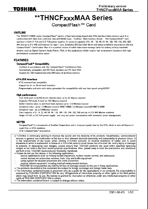
True IDE mode is required for CompactFlash Storage cards. All outputs from the card are totem pole except the data bus signals that are bi-directional tri-state.
Note: - 0.8V (Pulse width <= 10nS)
DC CHARACTERISTICS (Ta = 0℃ to 65℃, Vcc = 3.15V tccs VoH VoL PARAMETER Operating Current Sleep Mode Current High Level Output Voltage Low Level Output Voltage 2.4 0.4 MIN TYP 26 75 MAX 50 200 UNIT mA uA V V
Electrical Description The CompactFlash Storage Card functions in three basic modes: 1) PC Card ATA using I/O Mode, 2) PC Card ATA using Memory Mode and 3) True IDE Mode, which is compatible with most disk drives. CompactFlash Storage Cards are required to support all three modes. The CF Cards normally function in the first and second modes, however they can optionally function in True IDE mode. The configuration of the CompactFlash Card will be controlled using the standard PCMCIA configuration registers starting at address 200h in the Attribute Memory space of the storage card.or for True IDE Mode, pin 9 being grounded. The configuration of the CF Card will be controlled using configuration registers. The configuration registers are starting at the address defined in the Configuration Tuple (CISTPL_CONFIG) in the Attribute Memory space of the CF Card. Signals whose source is the host are designated as inputs while signals that the CompactFlash Storage Card sources are outputs. The CompactFlash Storage Card logic levels conform to those specified in the PCMCIA Release 2.1 specification. Each signal has three possible operating modes: 1) PC Card Memory mode 2) PC Card I/O mode 3) True IDE mode
无过载保护防爆漏电断路器(RCCB)8530 1-RCCB系列使用说明书

CN CN CN CN CN CN CN CN CN CN CN CN CN CN CN CN CN CN CN CN CN CN CNCN使用说明书其他语种 无过载保护防爆漏电断路器 (RCCB)8530/1-RCCB 系列– 保存以备将来使用! –内容目录1总体说明 (3)1.1制造商 (3)1.2关于本使用说明书 (3)1.3其他文档 (3)1.4标准和规定的符合性声明 (3)2符号说明 (4)2.1本使用说明书中的符号 (4)2.2设备上的符号 (4)3安全 (5)3.1设计用途 (5)3.2人员资格 (5)3.3残余风险 (6)4运输和仓储 (7)5产品选择、项目设计和修改 (7)5.1项目工程设计 (7)6装配和安装 (8)6.1安装/拆卸 (8)6.2装配 (10)7调试 (11)8运行 (11)8.1操作 (11)9维护、翻新、修理 (12)9.1维护 (12)9.2翻新 (12)9.3修理 (12)10退回 (13)11清洁 (13)12弃置处理 (13)13配件和备件 (13)14附录 A (14)14.1技术数据 (14)15附录 B (22)15.1设备设计 (22)15.2尺寸信息/固定尺寸 (23)2无过载保护防爆漏电断路器 (RCCB)8530/1-RCCB 系列299668 / 853********* 2023‐06‐27·BA00·III·zh·03总体说明3无过载保护防爆漏电断路器 (RCCB)8530/1-RCCB 系列1总体说明1.1制造商R.STAHL Schaltgeräte GmbHAm Bahnhof 3074638Waldenburg德国电话:+497942943-0传真:+497942943-4333网址:电子邮箱:****************1.2关于本使用说明书❝在使用前必须认真阅读本使用说明书,尤其是安全注意事项。
PADAUK Technology Co. Ltd PMC234 PMS234系列带12位ADC、采

PMC234/PMS234系列带12位ADC、采用FPPA TM技术双核心8位单片机数据手册第0.02版2015年10月30日Copyright 2015 by PADAUK Technology Co., Ltd., all rights reserved10F-2, No. 1, Sec. 2, Dong-Da Road, Hsin-Chu 300, Taiwan, R.O.C.重要声明应广科技保留权利在任何时候变更或终止产品,建议客户在使用或下单前与应广科技或代理商联系以取得最新、最正确的产品信息。
应广科技不担保本产品适用于保障生命安全或紧急安全的应用,应广科技不为此类应用产品承担任何责任。
关键应用产品包括,但不仅限于,可能涉及的潜在风险的死亡,人身伤害,火灾或严重财产损失。
应广科技不承担任何责任来自于因客户的产品设计所造成的任何损失。
在应广科技所保障的规格范围内,客户应设计和验证他们的产品。
为了尽量减少风险,客户设计产品时,应保留适当的产品工作范围安全保障。
提供本文档的中文简体版是为了便于了解,请勿忽视文中英文的部份,因为其中提供有关产品性能以及产品使用的有用信息,应广科技暨代理商对于文中可能存在的差错不承担任何责任,建议参考本文件英文版。
目录1.单片机特点 (8)1.1. 系列特点 (8)1.2. 高性能RISC CPU架构 (8)1.3. 系统功能 (8)1.4. 封装信息 (9)2.系统概述和方框图 (10)3.PMC234系列和引脚功能说明 (11)4.PMS234系列和引脚功能说明 (12)5.器件电气特性 (16)5.1. 直流/交流特性 (16)5.2. 绝对最大范围 (18)5.3. ILRC频率与VDD、温度关系的量测图 (19)5.4. IHRC频率与VDD、温度关系的量测图 (19)5.5. 工作电流量测值@系统时钟=ILRC÷N (20)5.6. 工作电流量测值@系统时钟=IHRC÷N (20)5.7. 工作电流量测值@系统时钟=1MH Z晶振EOSC÷N (21)5.8. 工作电流量测值@系统时钟=4MH Z晶振EOSC÷N (21)5.9. 工作电流量测值@系统时钟=32KH Z晶振EOSC÷N (22)5.10. IO引脚输出驱动电流(I OH)和灌电流(I OL)量测图 (22)5.11. 测量的IO输入阈值电压(V IH/V IL) (23)5.12. IO引脚拉高阻抗量测图 (23)5.13. 输出(VDD/2)偏置电压量测图与VDD关系的量测图 (23)5.14. 开机时序图 (24)5.15. 比较器响应时间量测(使用V) (25)INTERNAL R5.16. 比较器响应时间量测 (26)6.功能概述 (27)6.1. 处理单元 (27)6.1.1. 程序计数器 (28)6.1.2. 堆栈指针 (28)6.1.3. 一个处理单元工作模式 (29)6.2. OTP程序存储器 (30)6.2.1. 程序存储器分配 (30)6.2.2. 两个处理单元工作模式下程序存储器分配例子 (30)6.2.3. 一个处理单元工作模式下程序存储器分配例子 (31)6.3. 程序结构 (32)6.3.1. 两个处理单元工作模式下程序结构 (32)6.3.2. 一个处理单元工作模式下程序结构 (32)6.4. 启动程序 (33)6.5. 数据存储器 (34)6.6. 算术和逻辑单元 (35)6.7. 振荡器和时钟 (35)6.7.1. 内部高频振荡器(IHRC)和低频振荡器(ILRC) (35)6.7.2. 单片机校准 (35)6.7.3. IHRC频率校准和系统时钟 (36)6.7.4. 晶体振荡器 (37)6.7.5. 系统时钟和V LVR (Low Voltage Reset)水平 (39)6.7.6. 系统时钟切换 (39)6.8. 16位定时器(T IMER16) (41)6.9. 8位PWM定时器(T IMER2) (43)6.9.1. 使用Timer2产生定期波形 (44)6.9.2. 使用Timer2产生8位PWM波形 (45)6.9.3. 使用Timer2产生6位PWM波形 (47)6.10. 看门狗定时器 (48)6.11. 中断 (49)6.12. 掉电模式 (51)6.12.1. 省电模式(stopexe) (51)6.12.2. 掉电模式(stopsys) (52)6.12.3. 唤醒 (53)6.13. IO端口 (54)6.14. 复位和LVR (55)6.14.1. 复位 (55) (55)6.14.2. LVR6.15. 比较器 (56)6.15.1. 比较器硬件方块图 (56)6.15.2. 模拟讯号输入 (57)6.15.3. 内部参考电压(V internal R) (58)6.15.4. 比较器中断 (60)6.15.5. 比较器输出与Timer2同步 (60)6.15.6. 比较器响应时间 (60)6.15.7. 使用比较器 (61)6.15.8. 使用比较器和band-gap参考电压生成器 (61)6.16. VDD/2偏置电压 (62)6.17. 数字转换(ADC)模块 (63)6.17.1. AD转换的输入要求 (64)6.17.2. ADC分辨率选择 (65)6.17.3. ADC 时钟选择 (65)6.17.4. AD转换 (65)6.17.5. 模拟引脚的配置 (65)6.17.6. 使用ADC (65)7.IO寄存器 (67)7.1. 算术逻辑状态寄存器(FLAG),IO地址=0X00 (67)7.2. FPP单元允许寄存器(FPPEN),IO地址=0X01 (67)7.3. 堆栈指针寄存器(SP),IO地址=0X02 (67)7.4. 时钟控制寄存器(CLKMD),IO地址=0X03 (68)7.5. 中断允许寄存器(INTEN),IO地址=0X04 (68)7.6. 中断请求寄存器(INTRQ),IO地址=0X05 (69)7.7. T IMER16控制寄存器(T16M),IO地址=0X06 (69)7.8. 通用数据输入/输出寄存器(GDIO),IO地址=0X07 (70)7.9. 外部晶体振荡器控制寄存器(EOSCR),IO地址=0X0A (70)7.10. 内部高频RC振荡器控制寄存器(IHRCR,只写),IO地址=0X0B (70)7.11. 中断边沿选择寄存器(INTEGS,只写),IO地址=0X0C (70)7.12. 端口A数字输入禁止寄存器(PADIER,只写),IO地址=0X0D (71)7.13. 端口B数字输入禁止寄存器(PBDIER,只写),IO地址=0X0E (71)7.14. 端口A数据寄存器(PA),IO地址=0X10 (72)7.15. 端口A控制寄存器(PAC),IO地址=0X11 (72)7.16. 端口A上拉控制寄存器(PAPH),IO地址=0X12 (72)7.17. 端口B数据寄存器(PB),IO地址=0X14 (72)7.18. 端口B控制寄存器(PBC),IO地址=0X15 (72)7.19. 端口B上拉控制寄存器(PBPH),IO地址=0X16 (72)7.20. 端口C数据寄存器(PC),IO地址=0X17 (73)7.21. 端口C控制寄存器(PCC),IO地址=0X18 (73)7.22. 端口C上拉控制寄存器(PCPH),IO地址=0X19 (73)7.23. 端口D数据寄存器(PD),IO地址=0X1A (73)7.24. 端口D控制寄存器(PDC),IO地址=0X1B (73)7.25. 端口D上拉控制寄存器(PDPH),IO地址=0X1C (73)7.26. ADC控制寄存器(ADCC),IO地址=0X20 (74)7.27. ADC模式控制寄存器(ADCM,只写),IO地址=0X21 (75)7.28. ADC数据高位寄存器(ADCRH,只读),IO地址=0X22 (75)7.29. ADC数据低位寄存器(ADCRL,只读),IO地址=0X23 (75)7.30. 杂项寄存器(MISC),IO地址=0X3B (76)7.31. T IMER2控制寄存器(TM2C),IO地址=0X3C (77)7.32. T IMER2计数寄存器(TM2CT),IO地址=0X3D (77)7.33. T IMER2分频器寄存器(TM2S),IO地址=0X37 (78)7.34. T IMER2上限寄存器(TM2B),IO地址=0X09 (78)7.35. 比较器控制寄存器(GPCC),IO地址=0X3E (79)7.36. 比较器选择寄存器(GPCS),IO地址=0X22 (79)8.指令 (80)8.1. 数据传输类指令 (80)8.2. 算术运算类指令 (84)8.3. 移位运算类指令 (86)8.4. 逻辑运算类指令 (87)8.5. 位运算类指令 (89)8.6. 条件运算类指令 (90)8.7. 系统控制类指令 (92)8.8. 指令执行周期综述 (94)8.9. 指令影响标志的综述 (95)9.特别注意事项 (96)9.1. 使用IC时 (96)9.1.1. IO使用与设定 (96)9.1.2. 中断 (97)9.1.3. 切换系统时钟 (97)9.1.4. 掉电模式、唤醒以及看门狗 (98)9.1.5. TIMER溢出时间 (99)9.1.6. ADC使用注意事项 (99) (99)9.1.7. LVR9.1.8. 单/双核模式下指令周期差异 (99)PIN封装烧录方法 (100)9.1.9. 289.2. 使用IC时 (101)9.2.1. PMC234/PMS234系列于仿真器PDK3S-I-001/002/003上仿真时: (101)9.2.2. 使用PDK3S-I-001/002/003仿真PMC234/PMS234系列功能时注意事项: (102)修订历史:修订日期描述0.01 2015/8/1 第一版0.02 2015/10/30 增加1-4.封装信息: PMC234-Y24增加3.PMC234-Y24系列引脚功能描述P234C与PMC234/PMS234的主要差异列表P234C与PMC234/PMS234系列之间存在众多的差异。
MF_RC500_datasheet(中文)
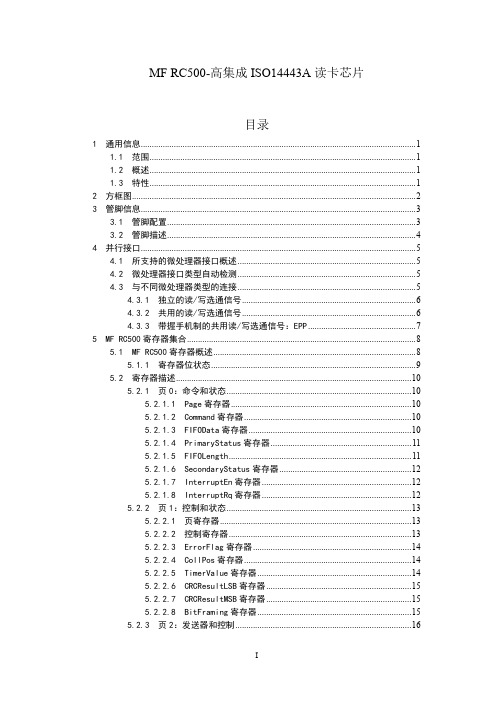
2 3
4Leabharlann 55.2.3.1 页寄存器 ....................................................................................... 16 5.2.3.2 TxControl 寄存器 ........................................................................ 16 5.2.3.3 CwConductance 寄存器 ................................................................ 16 5.2.3.4 PreSet13 寄存器 .......................................................................... 17 5.2.3.5 PreSet14 寄存器 .......................................................................... 17 5.2.3.6 ModWidth 寄存器 .......................................................................... 17 5.2.3.7 PreSet16 寄存器 .......................................................................... 17 5.2.3.8 PreSet17 寄存器 .......................................................................
电路保护器数据手册说明书

Rev.3-4-07052022
4
0&&6(0,&20
&XUYH&KDUDFWHULVWLFV
100000 10000
Fig. 1 - Peak Pulse Power Rating Curve
Non-repetitive pulse Waveform shown in Fig.3 TA= 25 OC
VRWM IR(µA)
1.5KE6.8A 1.5KE7.5A 1.5KE8.2A 1.5KE9.1A 1.5KE10A 1.5KE11A 1.5KE12A 1.5KE13A 1.5KE15A 1.5KE16A 1.5KE18A 1.5KE20A 1.5KE22A 1.5KE24A 1.5KE27A 1.5KE30A 1.5KE33A 1.5KE36A 1.5KE39A 1.5KE43A 1.5KE47A 1.5KE51A 1.5KE56A 1.5KE62A 1.5KE68A 1.5KE75A 1.5KE82A 1.5KE91A 1.5KE100A 1.5KE110A 1.5KE120A 1.5KE130A 1.5KE150A 1.5KE160A 1.5KE170A 1.5KE180A 1.5KE200A 1.5KE220A 1.5KE250A 1.5KE300A 1.5KE350A 1.5KE400A 1.5KE440A 1.5KE480A 1.5KE510A 1.5KE530A 1.5KE540A 1.5KE550A
D 1.000 ----- 25.40 -----
NOTE
Rev.3-4-07052022
4
0&&6(0,&20
1.5KE6.8(C)(A) THRU 1.5KE550(C)(A)
SGM8532中文资料
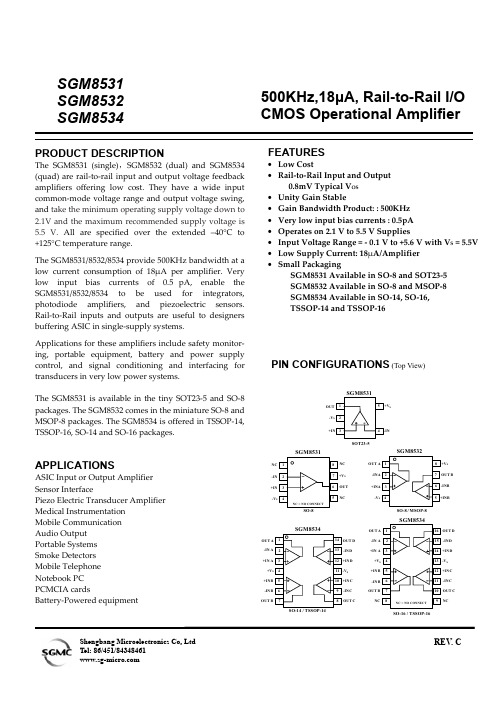
SGM8531 SGM8532 SGM8534PRODUCT DESCRIPTIONThe SGM8531 (single),SGM8532 (dual) and SGM8534 (quad) are rail-to-rail input and output voltage feedback amplifiers offering low cost. They have a wide input common-mode voltage range and output voltage swing, and take the minimum operating supply voltage down to 2.1V and the maximum recommended supply voltage is 5.5 V. All are specified over the extended –40°C to +125°C temperature range.The SGM8531/8532/8534 provide 500KHz bandwidth at a low current consumption of 18µA per amplifier. Very low input bias currents of 0.5pA, enable the SGM8531/8532/8534 to be used for integrators, photodiode amplifiers, and piezoelectric sensors. Rail-to-Rail inputs and outputs are useful to designers buffering ASIC in single-supply systems.Applications for these amplifiers include safety monitor- ing, portable equipment, battery and power supply control, and signal conditioning and interfacing for transducers in very low power systems.The SGM8531 is available in the tiny SOT23-5 and SO-8 packages. The SGM8532 comes in the miniature SO-8 and MSOP-8 packages. The SGM8534 is offered in TSSOP-14, TSSOP-16, SO-14 and SO-16 packages.APPLICATIONSASIC Input or Output Amplifier Sensor InterfacePiezo Electric Transducer Amplifier Medical Instrumentation Mobile Communication Audio Output Portable Systems Smoke Detectors Mobile Telephone Notebook PC PCMCIA cardsBattery-Powered equipment500KHz,18µA, Rail-to-Rail I/O CMOS Operational AmplifierFEATURES• Low Cost• Rail-to-Rail Input and Output0.8mV Typical V OS • Unity Gain Stable• Gain Bandwidth Product: : 500KHz • Very low input bias currents : 0.5pA • Operates on 2.1 V to 5.5 V Supplies• Input Voltage Range = - 0.1 V to +5.6 V with V S = 5.5V • Low Supply Current: 18µA/Amplifier • Small PackagingSGM8531 Available in SO-8 and SOT23-5 SGM8532 Available in SO-8 and MSOP-8 SGM8534 Available in SO-14, SO-16, TSSOP-14 and TSSOP-16PIN CONFIGURATIONS (Top View)S NC-V NC OUT S-V SOT23-5OUT B S -V SO-8 / MSOP-8OUT -IN A +IN A S +V -IN DD SO-16 / TSSOP-16-INB +IN B -IN C NCOUT BOUT C C D OUT +V -IN B +INB OUT BS -IN D+IN D -IN C OUT C+IN C OUT DShengbang Microelectronics Co, Ltd REV . CELECTRICAL CHARACTERISTICS : V S = +5V (At R L = 200kΩ connected to Vs/2 and V OUT = Vs/2, unless otherwise noted)Specifications subject to change without notice.PACKAGE/ORDERING INFORMATIONMODEL ORDER NUMBER PACKAGEDESCRIPTIONPACKAGE OPTION MARKING INFORMATIONSGM8531XN5/TRSOT23-5Tape and Reel, 30008531 SGM8531SGM8531XS/TR SO-8 Tape and Reel, 2500 SGM8531XS SGM8532XS/TR SO-8 Tape and Reel, 2500 SGM8532XS SGM8532SGM8532XMS/TRMSOP-8Tape and Reel, 3000SGM8532XMS SGM8534XS/TR SO-16 Tape and Reel, 2500SGM8534XSSGM8534XS14 SO-14Tube SGM8534XS14SGM8534XTS/TR TSSOP-16 Tape and Reel, 3000 SGM8534XTSSGM8534SGM8534XTS14 TSSOP-14TubeSGM8534XTS14ABSOLUTE MAXIMUM RATINGSSupply Voltage, V+ to V- ........................................... 7.5 VCommon-Mode Input Voltage.......................................... (–V S ) – 0.5 V to (+V S )+0.5VStorage Temperature Range.................. –65℃ to+150℃ Junction Temperature ................................................160℃ Operating Temperature Range ............ –55℃ to +150℃Package Thermal Resistance @ T A = 25℃SOT23-5, θJA .............................................................. 190/W ℃ SO-8, θJA ......................................................................125/W ℃ MSOP-8, θJA .............................................................. 216/W ℃ SO-16, θJA ..................................................................... 82/℃W TSSOP-16, θJA ............................................................ 105/W ℃ Lead Temperature Range (Soldering 10 sec).....................................................260℃ESD SusceptibilityHBM................................................................................4000V MM (400V)NOTES1. Stresses above those listed under Absolute Maximum Ratings may cause permanent damage to the device. This is a stress rating only; functional operation of the device at these or any other conditions above those indicated in the operational section of this specification is not implied. Exposure to absolute maximum rating conditions for extended periods may affect device reliability.CAUTIONThis integrated circuit can be damaged by ESD. Shengbang Micro-electronics recommends that all integrated circuits be handled with appropriate precautions. Failure to observe proper handling and installation procedures can cause damage.ESD damage can range from subtle performance degradation to complete device failure. Precision integrated circuits may be more susceptible to damage because very small parametric changes could cause the device not to meet its published specifications.TYPICAL PERFORMANCE CHARACTERISTICSAt T A = +25℃, V S = +5V , and R L =200k Ω connected to Vs/2,unless otherwise noted.Small-Signal Step Response Small-Signal Step Response10µs/div 10µs/divG = +1C L = 100pF R L = 5K ΩG = +1 C L = 100pF R L= 200K ΩG = +1 C L = 100pF R L= 200K Ω20m V /d i v50m V /d i v500m V /d i vLarge-Signal Step Response20µs/divTYPICAL PERFORMANCE CHARACTERISTICS At T A= +25℃, V S = +5V, and R L=200kΩ connected to Vs/2,unless otherwise noted.TYPICAL PERFORMANCE CHARACTERISTICSAt T A = +25℃, V S = +5V , and R L =200k Ω connected to Vs/2,unless otherwise noted.2.5V0V 250mV0VVs = 5V G = -10 V IN = 250mVTime(20μs/div)Overload Recovery TimeAPPLICATION NOTESDriving Capacitive LoadsThe SGM853X can directly drive 250pF in unity-gain without oscillation. The unity-gain follower (buffer) is the most sensitive configuration to capacitive loading. Direct capacitive loading reduces the phase margin of amplifiers and this results in ringing or even oscillation. Applications that require greater capacitive drive capability should use an isolation resistor between the output and the capacitive load like the circuit in Figure 1. The isolation resistor R ISO and the load capacitor C L form a zero to increase stability. The bigger the R ISO resistor value, the more stable V OUT will be. Note that this method results in a loss of gain accuracy because R ISO forms a voltage divider with the R LOAD.V IN V OUTFigure 1. Indirectly Driving Heavy Capacitive LoadAn improvement circuit is shown in Figure 2, It provides DC accuracy as well as AC stability. R F provides the DC accuracy by connecting the inverting signal with the output, C F and R Iso serve to counteract the loss of phase margin by feeding the high frequency component of the output signal back to the amplifier’s inverting input, thereby preserving phase margin in the overall feedback loop.V IN V OUTFigure 2. Indirectly Driving Heavy Capacitive Load with DC AccuracyFor no-buffer configuration, there are two others ways to increase the phase margin: (a) by increasing the amplifier’s gain or (b) by placing a capacitor in parallel with the feedback resistor to counteract the parasitic capacitance associated with inverting node. Power-Supply Bypassing and Layout The SGM853X family operates from either a single +2.5V to +5.5V supply or dual ±1.25V to ±2.75V supplies. For single-supply operation, bypass the power supply V DD with a 0.1µF ceramic capacitor which should be placed close to the V DD pin. For dual-supply operation, both the V DD and the V SS supplies should be bypassed to ground with separate 0.1µF ceramic capacitors. 2.2µF tantalum capacitor can be added for better performance.VnVpV SSV SS(GND)Figure 3. Amplifier with Bypass CapacitorsTypical Application Circuits Differential AmplifierThe circuit shown in Figure 4 performs the difference function. If the resistors ratios are equal ( R4 / R3 = R2 / R1 ), thenV OUT = ( Vp – Vn ) × R2 / R1 + Vref.Vn VpOUT Figure 4. Differential AmplifierInstrumentation AmplifierThe circuit in Figure 5 performs the same function as that in Figure 4 but with the high input impedance.Vn VpV OUT Figure 5. Instrumentation AmplifierLow Pass Active FilterThe low pass filter shown in Figure 6 has a DC gain of ( - R2 / R1 ) and the –3dB corner frequency is 1/2πR2C. Make sure the filter is within the bandwidth of the amplifier. The Large values of feedback resistors can couple with parasitic capacitance and cause undesired effects such as ringing or oscillation in high-speed amplifiers. Keep resistors value as low as possible and consistent with output loading consideration.V INV OUT Figure 6. Low Pass Active FilterPACKAGE OUTLINE DIMENSIONS SOT23-5PACKAGE OUTLINE DIMENSIONS SO-8PACKAGE OUTLINE DIMENSIONS MSOP-8PACKAGE OUTLINE DIMENSIONS SO-16PACKAGE OUTLINE DIMENSIONS TSSOP-16PACKAGE OUTLINE DIMENSIONS SO-14PACKAGE OUTLINE DIMENSIONS TSSOP-14REVISION HISTORYLocation Page 11/06— Data Sheet changed from REV.A to REV.BChanges to ABSOLUTE MAXIMUM ATINGS . . . . . . . . . . . . . . . . . . . . . . . . . . . . . . . .. . . . . . . . . . . . . . . . . . . . . . . . . . .. . . . . . . 3 05/07— Data Sheet changed from REV.B to REV.CAdds SO-14 and TSSOP-14 Package . . . . . . . . . . . . . . . . . . . . . . . . . . . . . . . . . . . . . . . . . . . . . . . .. . . . . . . . . . . . . . . . .. 1,3,14,15Shengbang Microelectronics Co, LtdUnit 3, ChuangYe PlazaNo.5, TaiHu Northern Street, YingBin Road Centralized Industrial ParkHarbin Development ZoneHarbin, HeiLongJiang 150078P.R. ChinaTel.: 86-451-84348461Fax: 86-451-84308461。
PF9833 三相 PWM 专用测试仪 用户手册说明书
PF9833三相PWM专用测试仪用户手册Ver2.05PF98333ΦPWM DIGITAL POWER METERUSER’S MANUALVer2.05杭州远方光电信息股份有限公司EVERFINE Corporation(Stock Code:300306)地址:杭州市滨江区滨康路669号1号楼(310053)ADD:Bldg1,#669Binkang Rd.,Binjiang Hi-Tech Zone,Hangzhou(310053),ChinaTel:86-571-86698333Fax:86-571-86696433E-mail:Sales@销售专箱Service@服务专箱http://杭州远方光电信息股份有限公司版权所有,未经许可不得复制和传播前言感谢购置远方PF9833三相PWM专用测试仪。
本用户手册包含仪器功能、操作过程以及安全规定等,为了确保正确使用本仪器,在操作仪器前请仔细阅读手册。
请妥善保存手册,以便碰到问题时能快速查阅。
注意:● 本公司奉行不断完善改进产品的宗旨,因此手册内容有可能改变,恕不另行通知。
● 我们已经尽最大努力准备本手册以确保其准确性,如果有疑问或发现错误,请直接与本公司或本公司授权代理商联系。
● 对于手册内容如有不同理解,以本公司技术部门解释为准。
开箱检查用户第一次打开仪器包装箱时,请对照装箱清单检查仪器和配件,若发现仪器或配件错误、配件不齐或是不正常,请与销售商或生产商联系。
杭州远方光电信息股份有限公司版权所有,未经许可不得复制和传播。
1版权申明The copyright of this manual and the related information belongs to EVERFINE,and it is protected by the copyright law of Peoples Republic of China and other relevant international treaties.Copying,modifying,spreading, excerpting,backing up or translating the whole or part contents of this manual by any company or personnel without the written permission of EVERFINE is prohibited.Otherwise it will be treated as infringement and the infringer will assume law responsibility and all loss of EVERFINE.Any infringement related above can be traced back to the responsible user by the unique product number printed in the manual.If EVERFINE has signed a written agreement with user and the contents in the agreement are in conflict with above terms,the contents in the written agreement have preferential force effect.本用户手册及包括的任何资料,其版权归远方公司所有,受中华人民共和国著作权法或国际相关法律保护。
- 1、下载文档前请自行甄别文档内容的完整性,平台不提供额外的编辑、内容补充、找答案等附加服务。
- 2、"仅部分预览"的文档,不可在线预览部分如存在完整性等问题,可反馈申请退款(可完整预览的文档不适用该条件!)。
- 3、如文档侵犯您的权益,请联系客服反馈,我们会尽快为您处理(人工客服工作时间:9:00-18:30)。
元器件交易网
Electrical Characteristics TA = 25°C unless otherwise noted
Symbol
Parameter
Test Conditions
Min
Off Characteristics
BVDSS
Drain-Source Breakdown Voltage
Thermal Characteristics
RθJA RθJA RθJA RθJA
Thermal Resistance, Junction-to-Ambient Thermal Resistance, Junction-to-Ambient Thermal Resistance, Junction-to-Ambient Thermal Resistance, Junction-to-Ambient
-
Schottky Diode Characteristic
IR
Reverse Leakage
VF
Forward Voltage
VR = 20V IF = 500mA
TJ = 25°C
-
TJ = 85°C-TJ = 125°C -
TJ = 25°C
-
TJ = 125°C -
Typ Max Units
General Description
This device is designed specifically as a single package solution for the battery charge switch in cellular handset and other ultra-portable applications. It features a MOSFET with low on-state resistance and an independently connected low forward voltage schottky diode for minimum conduction losses.
(Note 1a) (Note 1b) (Note 1c) (Note 1d)
Package Marking and Ordering Information
Device Marking .853
Device FDFMA2P853
Reel Size 7inch
Tape Width 8mm
4S
Ratings -20 ±8 -2.2 -6 20 1 1.4 0.7
-55 to +150
Units V V
A
V A
W oC
86
173
oC/W
86
140
Quantity 3000 units
©2005 Fairchild Semiconductor Corporation
1
FDFMA2P853 Rev. C (W)
FDFMA2P853 Integrated P-Channel PowerTrench® MOSFET and Schottky Diode
-
VSD
Drain-Source Diode Forward Voltage VGS = 0V, IS = -1.1 A (Note 2) -
trr Qrr
Diode Reverse Recovery Time
-
Diode Reverse Recovery Charge
IF= -3.0A, dIF/dt=100A/µs
6 VGS = -4.5V
5 -3.5V
4
3
-2.5V -3.0V
-2.0V -1.8V
2 -1.5V
1
0
0
0.5
1
1.5
2
2.5
-VDS, DRAIN-SOURCE VOLTAGE (V)
Figure 1. On-Region Characteristics
元器件交易网
FDFMA2P853 Integrated P-Channel PowerTrench® MOSFET and Schottky Diode
August 2005
FDFMA2P853
Integrated P-Channel PowerTrench® MOSFET and Schottky Diode
-
-
V
-12
- mV/°C
-
-1
µA
-
±100 nA
-0.7 -1.5
V
2
- mV/°C
90
120
120 160 172 240 mΩ
118 160
-
-
A
7
-
S
435
-
pF
80
-
pF
45
-
pF
9
18
ns
11
19
ns
15
27
ns
6
12
ns
4
6
nC
0.8
-
nC
0.9
-
nC
-
-1.1
A
-0.8 -1.2
V
Low Profile - 0.8 mm maximun - in the new package MicroFET 2x2 mm
Schottky:
PIN A
VF < 0.46 V @ 500 mA
NC D
A1
6C
C
D
NC 2
5G
D3
MicroFET C G S
Absolute Maximum Ratings TA = 25°C unless otherwise noted
-
VDD = -10V, ID = -1A
-
VGS = -4.5V, RGEN = 6Ω
-
-
-
VDS = -10V, ID = -3.0A, VGS = -4.5V
-
Drain-Source Diode Characteristics and Maximum Ratings
IS
Maximum Continuous Drain-Source Diode Forward Current
3
FDFMA2P853 Rev. C (W)
元器件交易网
FDFMA2P853 Integrated P-Channel PowerTrench® MOSFET and Schottky Diode
Typical Characteristics
-ID, DRAIN CURRENT (A)
design while RθJA is determined by the user's board design. (a) MOSFET RθJA = 86°C/W when mounted on a 1 in2 pad of 2 oz copper, 1.5" x 1.5" x 0.062" thick PCB
VGS = 0V, ID = -250µA
-20
∆BVDSS ∆TJ
Breakdown Voltage Temperature Coefficient
ID = -250µA, Referenced to 25°C
-
IDSS
Zero Gate Voltage Drain Current
VDS = -16V, VGS = 0V
ID = -250µA, Referenced to 25°C
-
VGS = -4.5V, ID = -3.0A
-
VGS = -2.5V, ID = -2.5A
-
RDS(ON)
Static Drain-Source On-Resistance
VGS = -1.8V, ID = -1.0A
-
VGS = -4.5V, ID = -3.0A TJ = 125°C
Electrical Characteristics TA = 25°C unless otherwise noted
Notes:
1. RθJA is determined with the device mounted on a 1 in2 oz. copper pad on a 1.5 x 1.5 in. board of FR-4 material. RθJC is guaranteed by
-
VDS = -10V, VGS = 0V, f = 1.0MHz
-
Crss
Reverse Transfer Capacitance
-
Switching Characteristics (Note 2)
td(on) tr td(off) tf Qg Qgs Qgd
Turn-On Delay Time Turn-On Rise Time Turn-Off Delay Time Turn-Off Fall Time Total Gate Charge Gate-Source Charge Gate-Drain Charge
Power dissipation for Single Operation Power dissipation for Single Operation
(Note 1a)
(Note 1a) (Note 1b)
TJ, TSTG Operating and Storage Junction Temperature Range
c) 86oC/W when mounted on a 1in2 pad of 2 oz copper
d) 140oC/W when mounted on a minimum pad of 2 oz copper
