02_Ethernet
EtherNet IP直接输入型步进电机控制器(伺服24VDC)系列JXC91 安装与维护手册说明书

Installation & Maintenance Manual EtherNet/IP Direct input typeStep Motor Controller (Servo 24VDC)Series JXC91This manual contains essential information for the protection of users and others from possible injury and/or equipment damage.•Read this manual before using the product, to ensure correct handling,and read the manuals of related apparatus before use.•Keep this manual in a safe place for future reference.•These instructions indicate the level of potential hazard by label of "Caution", "Warning" or "Danger", followed by important safety information which must be carefully followed.•To ensure safety of personnel and equipment the safety instructions in this manual and the product catalogue must be observed, along with other relevant safety practices.WarningWarningThe compatibility of the product is the responsibility of the person who designs the equipment or decides its specifications.Since the product specified here is used under various operatingconditions, its compatibility with specific equipment must be decided by the person who designs the equipment or decides its specifications based on necessary analysis and test results.The expected performance and safety assurance of the equipment will be the responsibility of the person who has determined its compatibility with the product.This person should also continuously review all specifications of the product referring to its latest catalog information, with a view to giving due consideration to any possibility of equipment failure when configuring the equipment.Only personnel with appropriate training should operate machinery and equipment.The product may become unsafe if handled incorrectly.The assembly, operation and maintenance of machines or equipment must be performed by an operator who is appropriately trained and experienced.Do not attempt to service or replace product and machinery/equipment until safety is confirmed.1. The inspection and maintenance of machinery/equipment should only be performed after measures to prevent falling or runaway of the driven objects have been confirmed.2. When the product is to be removed, confirm that the above safety measures are implemented and the power from any appropriate source is cut, and read and understand the specific product precautions of all relevant products carefully.3. Before machinery/equipment is restarted, take measures to prevent unexpected operation and malfunction.CautionThe product is provided for use in manufacturing industries.The product herein described is basically provided for peaceful use in manufacturing industries.If considering using the product in other industries, consult SMC beforehand and provide specifications or a contract, if necessary.If anything is unclear, contact your nearest sales branch.Refer to the operation manual on the SMC website (URL ).Contact SMC beforehand and take special consideration of safety measures if the product is to be used in any of the following conditions:1. Conditions and environments outside of the given specifications, or use outdoors or in a place exposed to direct sunlight.2. Installation on equipment in conjunction with atomic energy, railways,air navigation, space, shipping, vehicles, military, medical treatment,combustion and recreation, or equipment in contact with food and beverages, emergency stop circuits, clutch and brake circuits in press applications, safety equipment or other applications unsuitable for the standard specifications described in the product catalog.3. An application which could have negative effects on people, property, or animals requiring special safety analysis.4. Use in an interlock circuit, which requires the provision of doubleinterlock for possible failure by using a mechanical protective function,and periodical checks to confirm proper operation.WarningThe Communication cable must be connected to a PC using a USB cable through a conversion unit.Do not connect the teaching box to a PC.Do not use LAN cable to connect to the controller, as this may cause damage to the personal computer.2 Product configurationTo P1, P2∗1∗1●ControllerOptionsPLCTo SIPCorEtherNet/IP Controller power supply 24VDC•Power supply plug (Included)<Applicable wire size>AWG20 (0.5mm )•Communication cable •Conversion unit•Controller set up kit (Controller settingsoftware, communication cable, conversion unit,USB cable are included)Part No: LEC-W2•Teaching box(3m cable is provided.)Product number:LEC-T1-3□G□•USB cable (A-mini B type)∗1 These items are included when ordered using the part number for an actuator set.∗2 The latest version of the controller setting software must be used.Upgrade software can be downloaded from SMC website./Electric actuatorTo ENCTo MOT To PWRLED displayRefer to the table below for the details of the LED status.∗2CautionDo not turn OFF the input power supply for the controller or disconnect and connect the cable while the data is being written to EEPROM (PWR LED (green) is flashing).∗Possibility of incorrect/corrupted data (step data, parameter)•Actuator cable(Robotic type cable)Model number:•LE-CP-□-□(Robotic type cable)•LE-CP-□-□-S (Standard cable)•Conversion cable Product no.:P5062-5(2) GroundingPlace the grounding cable with crimped terminal between the M4 screw and shakeproof washer as shown below and tighten the screw.Refer to the operation manual on SMC website (URL ).CautionThe M4 screw, cable with crimped terminal and shakeproof washer must be prepared by the user.The controller must be connected to Ground to reduce noise.URL (Global) (Europe)Specifications are subject to change without prior notice from the manufacturer.© 2016 SMC Corporation All Rights Reserved13 ContactsAUSTRIA (43) 2262 62280-0NETHERLANDS (31) 20 531 8888 BELGIUM (32) 3 355 1464 NORWAY (47) 67 12 90 20 CZECH REP.(420) 541 424 611 POLAND (48) 22 211 9600 DENMARK (45) 7025 2900 PORTUGAL (351) 21 471 1880FINLAND (358) 207 513513 SLOVAKIA (421) 2 444 56725 FRANCE (33) 1 6476 1000 SLOVENIA (386) 73 885 412GERMANY (49) 6103 4020 SPAIN (34) 945 184 100 GREECE (30) 210 271 7265 SWEDEN(46) 8 603 1200 HUNGARY (36) 23 511 390 SWITZERLAND (41) 52 396 3131 IRELAND (353) 1 403 9000 UNITED KINGDOM(44) 1908 563888ITALY(39) 02 92711BULGARIA (359) 2 974 4492ESTONIA (372) 651 0370 ROMANIA (40) 21 320 5111LATVIA (371) 781 77 00 LITHUANIA(370) 5 264 8126 12 TroubleshootingRefer to the operation manual on the SMC website (URL ).(1) MountingThe controller can be direct mounted using screws or mounted on a DIN rail.Details of the controller mounting options are shown below.Mounting directionBasic specifications[1] Direct mounting (JXC917-□)(Mounting with two M4 screws)Mounting directionGround wire[2] DIN rail mounting (JXC918-□)(Mounting with DIN rail)Hook the controller on the DIN rail andpress lever A in the direction of the arrow to lock it.Ground wireBefore locked onto DIN railLocked onto DIN railGround wireDIN railACable with crimping terminal M4 screwShakeproof washerControllerPower supply plug specificationsThe specifications of the power supply plug supplied with the controller are shown below.Power supply plugIP address×Manual setting of IP address8 Initial Setting methodSetting of switch (IP address)Turn OFF the power supply while setting the switch.The rotary switch should be set with a small flat blade screwdriver.Refer to the operation manual on the SMC website (URL ).。
02_PF4000与电脑的连接

ToolsTalk与PF4000的串口连接
2,连接PF控制器:
方法一: 单击:Focus – Serial – Serial PF -- Connect
方法二: 双击此处
பைடு நூலகம்
ToolsTalk与PF4000的USB连接
用USB电缆把PC机与PF4000控制器连接好以后,按以下操 作就可以连接。
方法一: 单击:Focus – Serial – Serial PF -- Connect
2,基本型控制器的IP设置:
Step01,按F按钮8次,直到画面上交替显示F8和Addr 时,按回车按钮。 Step02,输入IP地址,每输入一个值后都按回车按钮一次 用于保存。(共按四次回车按钮。如:“192,回车, 168,回车,0,回车,1,回车”) Step03,输入子网掩码每输入一个值后都按回车按钮一次 用于保存。(共按四次回车按钮。如:“255,回车, 255,回车,255,回车,0,回车”) Step04,输入网关,每输入一个值后都按回车按钮一次 用于保存。(共按四次,若没有网关,则按四 次回车按钮) Step05,按回车按钮用于回到主界面后,IP设置完毕。
ToolsTalk与PF4000的以太网连接
3,PC机的IP地址:
PC机与PF 控制器通过网 线连接后,双击PC机右 下角的”我的电脑”图标,打 开TCP/IP设置画面。使 PC的IP,子网掩码与PF Controller的IP保持在同 一个频段内。
PC与PF Controller的 IP和子网掩码 保持在同一个频段内。
1,PF4000图表型控制器的IP设置 2,PF4000基本型控制器的IP设置 3,PC机的IP设置 4,Toolstalk的IP设置 5,连接
AAA认证的配置
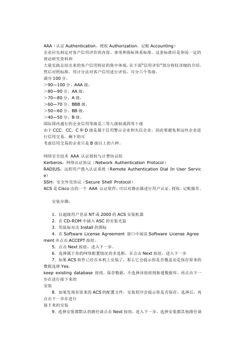
AAA(认证Authentication,授权Authorization,记帐Accounting)企业应先制定对客户信用评价的内容、事项和指标体系标准,这套标准应是参阅一定的理论研究资料和大量实践总结出来的客户信用特征的集中体现,在下面“信用评价”部分将较详细的介绍。
然后对照标准,用计分法对客户信用进行评估,可分六个等级。
满分100分,>90—100分、AAA级,>80—90分、AA级,>70—80分、A级,>60—70分、BBB级,>50—60分、BB级,>40—50分、B级。
国际国内通行的企业信用等级是三等九级制或四等十级由于CCC、CC、C和D级是属于信用警示企业和失信企业,因此要避免和这些企业进行信用交易,剩下的可考虑信用交易的企业只是B级以上的六种。
网络安全技术AAA 认证授权与计费协议组Kerberos:网络认证协议(Network Authentication Protocol)RADIUS:远程用户拨入认证系统(Remote Authentication Dial In User Servic e)SSH:安全外壳协议(Secure Shell Protocol)ACS是Cisco出的一个AAA 认证软件,可以对路由器进行用户认证、授权、记账操作。
安装步骤:1.以超级用户登录NT或2000的ACS安装机器2.在CD-ROM中插入ASC的安装光盘3.用鼠标双击Install的图标4.在Software License Agreement 窗口中阅读Software License Agree ment并点击ACCEPT按纽。
5.点击Next按纽,进入下一步。
6.选择属于你的网络配置情况的多选框,在点击Next按纽,进入下一步7.如果ACS软件已经在本机上安装了,那么它会提示你是否覆盖还是保存原来的数据选择Yes,keep existing database 按纽,保存数据,不选择该按纽则新建数据库,再点击下一步在进行接下来的安装8.如果发现有原来的ACS的配置文件,安装程序会提示你是否保存,选择后,再点击下一步在进行接下来的安装9.选择安装都默认的路径请点击Next按纽,进入下一步,选择安装都其他路径请点击Browse按纽,选择路径。
ABB DRIVES FEPL-02 Ethernet POWERLINK 适配器模块快速安装和启动

4. Tighten the screw to torque 0.8 N·m using a Torx TX10 screwdriver.
4
WARNING! Do not use excessive force, or leave the screw too loose. Over-tightening can damage the screw or module. A loose screw decreases the EMC performance, and can cause an operation failure.
3AXD50000158164 Rev B (EN) 2023-01-25
Further information
See the latest version of FEPL-02 Ethernet POWERLINK adapter For more information on ABB fieldbus options and protocols,
module user's manual (3AUA0000123527 [English]) in ABB library see the fieldbus communications web page
(/drives/documeivity/fieldbus-connectivity).
—
OPTIONS FOR ABB DRIVES
FEPL-02 Ethernet POWERLINK adapter module Quick installation and start-up guide
Safety instructions
WARNING! Obey the safety instructions of the drive. If you ignore them, injury or death, or damage to the equipment can occur.
华三交换机-路由器配置命令
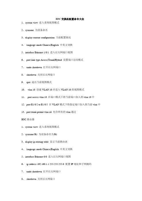
H3C交换机配置命令大全1、system-view 进入系统视图模式2、sysname 为设备命名3、display current-configuration 当前配置情况4、language-mode Chinese|English 中英文切换5、interface Ethernet 1/0/1 进入以太网端口视图6、port link-type Access|Trunk|Hybrid 设置端口访问模式7、undo shutdown 打开以太网端口8、shutdown 关闭以太网端口9、quit 退出当前视图模式10、vlan 10 创建VLAN 10并进入VLAN 10的视图模式11、port access vlan 10 在端口模式下将当前端口加入到vlan 10中12、port E1/0/2 to E1/0/5 在VLAN模式下将指定端口加入到当前vlan中13、port trunk permit vlan all 允许所有的vlan通过H3C路由器1、system-view 进入系统视图模式2、sysname R1 为设备命名为R13、display ip routing-table 显示当前路由表4、language-mode Chinese|English 中英文切换5、interface Ethernet 0/0 进入以太网端口视图6、ip address 192.168.1.1 255.255.255.0 配置IP地址和子网掩码7、undo shutdown 打开以太网端口8、shutdown 关闭以太网端口9、quit 退出当前视图模式10、ip route-static 192.168.2.0 255.255.255.0 192.168.12.2 description To.R2 配置静态路由11、ip route-static 0.0.0.0 0.0.0.0 192.168.12.2 description To.R2 配置默认的路由H3C S3100 SwitchH3C S3600 SwitchH3C MSR 20-20 Router1、调整超级终端的显示字号;2、捕获超级终端操作命令行,以备日后查对;3、language-mode Chinese|English 中英文切换;4、复制命令到超级终端命令行,粘贴到主机;5、交换机清除配置:<H3C>reset save ;<H3C>reboot ;6、路由器、交换机配置时不能掉电,连通测试前一定要检查网络的连通性,不要犯最低级的错误。
华为路由器交换机配置
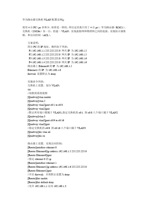
华为路由器交换机VLAN配置实例()使用4台PC(pc多和少,原理是一样的,所以这里我只用了4台pc),华为路由器(R2621)、交换机(S3026e)各一台,组建一VLAN,实现虚拟网和物理网之间的连接。
实现防火墙策略,和访问控制(ACL)。
方案说明:四台PC的IP地址、掩码如下列表:P1 192.168.1.1 255.255.255.0 网关IP为192.168.1.5P2 192.168.1.2 255.255.255.0 网关IP为192.168.1.5P3 192.168.1.3 255.255.255.0 网关IP为192.168.1.6P4 192.168.1.4 255.255.255.0 网关IP为192.168.1.6路由器上Ethernet0的IP为192.168.1.5Ethernet1的IP为192.168.1.6firewall 设置默认为deny实施命令列表:交换机上设置,划分VLAN:sys//切换到系统视图[Quidway]vlan enable[Quidway]vlan 2[Quidway-vlan2]port e0/1 to e0/8[Quidway-vlan2]quit//默认所有端口都属于VLAN1,指定交换机的e0/1 到e0/8八个端口属于VLAN2[Quidway]vlan 3[Quidway-vlan3]port e0/9 to e0/16[Quidway-vlan3]quit//指定交换机的e0/9 到e0/16八个端口属于VLAN3[Quidway]dis vlan all[Quidway]dis cu路由器上设置,实现访问控制:[Router]interface ethernet 0[Router-Ethernet0]ip address 192.168.1.5 255.255.255.0[Router-Ethernet0]quit//指定ethernet 0的ip[Router]interface ethernet 1[Router-Ethernet1]ip address 192.168.1.6 255.255.255.0[Router-Ethernet1]quit//开启firewall,并将默认设置为deny[Router]fire enable[Router]fire default deny//允许192.168.1.1访问192.168.1.3//firewall策略可根据需要再进行添加[Router]acl 101[Router-acl-101]rule permit ip source 192.168.1.1 255.255.255.0 destination 192.168.1.3 255.255.255.0[Router-acl-101]quit//启用101规则[Router-Ethernet0]fire pa 101[Router-Ethernet0]quit[Router-Ethernet1]fire pa 101[Router-Ethernet1]quit华为QuidWay交换机配置命令手册华为QuidWay交换机配置命令手册:1、开始建立本地配置环境,将主机的串口通过配置电缆与以太网交换机的Console口连接。
CentOS 7 单网卡多IP配置
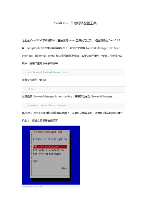
CentOS 7 下的网络配置工具之前在CentOS 6下编辑网卡,直接使用setup工具就可以了。
但在新版的CentOS 7里,setuptool已经没有网络编辑组件了,取而代之的是NetworkManager Text User Interface,即nmtui。
nmtui默认随系统标准安装,如果你使用最小化安装,可能没有该软件,使用下面的命令手动安装:再次运行nmtui,即可看到网络编辑界面了,这里可以编辑连接、激活新网络连接和设置主机名字,根据实际需要选择即可:一、nmtui手工添加IP看一下当前网络设备的IP,为了精简指令输出,指令就要复杂一些了:view sourceprint?01.[root@centos7 ~]#nmcli -t -f IP4.ADDRESS dev show enp0s302.IP4.ADDRESS[1]:ip = 192.168.150.110/24, gw = 192.168.150.25403.[root@centos7 ~]#04.[root@centos7 ~]#ipaddr show enp0s3 scope global05.2: enp0s3: <BROADCAST,MULTICAST,UP,LOWER_UP>mtu 1500 qdiscpfifo_fast state UP qlen 100006.link/ether 08:00:27:15:35:d2 brdff:ff:ff:ff:ff:ff07.inet 192.168.150.110/24 brd 192.168.150.255 scope global enp0s308.valid_lft forever preferred_lft forever09.[root@centos7 ~]#10.[root@centos7 ~]# cat /etc/sysconfig/network-scripts/ifcfg-eth011.......12.IPADDR0=192.168.150.11013.PREFIX0=2414.GATEWAY0=192.168.150.25415.DNS1=192.168.150.25416.HWADDR=08:00:27:15:35:D217.IPADDR1=192.168.150.11118.PREFIX1=2419.[root@centos7 ~]#新IP已经被加入到ifcfg-eth0中,原始地址的关键字是IPADDR0、PREFIX0,新地址的关键字是IPADDR1、PREFIX1 。
ACS550用户手册

警告 ! 不要使用断路设备来起停电机,而应通过控制变频器的起停来控制电机。直流 侧电解电容所允许的最大充放电次数为每 10 分钟内 5 次。 警告!如果变频器用在浮地电网或高阻接地(大于30欧姆)电网时,请断开内部EMC滤 波器的连接,否则系统将通过 EMC 滤波电容接地。可能会导致危险或损坏变频器。 如果变频器用在角接地 TN 电网时,请断开内部 EMC 滤波器的连接,否则将损坏变 频器。 注意断开 EMC 滤波器连接后,变频器将不具有 EMC 兼容性。 参见相关章节 " 断开内部 EMC 滤波器 ",第 17 页。也参见相关章节 " 不对称接地电 网、 " 和 " 浮地电网 ",第 232 页。 警告 ! 不要试图在变频器上电的时候安装或拆卸 EM1, EM3, F1 或 F2 螺钉。
RECA-01 EtherCAT 总线适配器用户手册 3AUA0000043520 ( 英文 )
REPL-01 Ethernet POWERLINK 总线适配器用户手册 3AUA0000052289 ( 英文 )
ACS550 User’s Manual
RETA-01 Ethernet 总线适配器用户手册 3AFE64539736 ( 英文 ) RETA-02 Ethernet 总线适配器用户手册 3AFE68895383 ( 英文 ) RLON-01 LonWorks 总线适配器用户手册 3AFE64798693 ( 英文 ) RPBA-01 PROFIBUS-DP 总线适配器用户手册 3AFE64504215 ( 英文 ) RETA-01 Ethernet 总线适配器用户手册 3AUA0000042896 ( 英文 )
2024版思科网络交换机配置命令详细总结归纳

VLAN间路由配置
01 02 03 04
使用`interface`命令进入三层接口配置模式,如`interface vlan 10`进入 VLAN 10的三层接口。
源端口和目的端口散列
同时考虑数据包的源端口和目的端口进行负载均衡。
配置负载均衡策略
在全局配置模式下使用`port-channel load-balance`命令进行配置。
端口聚合故障排除技巧
01
检查物理连接
确保所有参与聚合的物理端口都已 正确连接。
03
检查交换机配置
确认交换机的配置是否正确,包括 聚合模式、聚合组号等。
限制登录用户
指定允许通过SSH远程登录的用户或用户组。
交换机日志与审计功能启用
启用日志功能
将交换机操作记录到日志文件中,方便后续 审计和分析。
远程日志服务器
将日志文件发送到远程日志服务器进行集中 存储和管理。
配置日志级别
根据需要设置日志记录的详细程度(如信息、 警告、错误等)。
审计功能
启用审计功能,对特定操作进行实时监控和 记录。
思科网络交换机配置命令详细 总结归纳
目 录
• 交换机基本配置 • VLAN配置与管理 • 生成树协议(STP)配置与优化 • 端口聚合(EtherChannel)配置与应用 • 交换机安全性设置与加固 • 交换机性能监控与故障排除
01
交换机基本配置
交换机登录与访问控制
1 2
通过控制台端口登录 使用终端仿真软件通过控制台端口连接到交换机, 输入用户名和密码进行登录。
802.3帧和EthernetII帧格式的区别
局域网包括:以太网、令牌环、光纤分布式数据接口FDDI。
IP数据报必须用数据链路层的报文和报尾封装后才能在物理媒介上发送。
数据链路层的报文和报尾提供以下服务:1. 定界帧彼此分开。
每个帧的开始和结束位置被标出,其有效负载也与报头报尾分开。
2. 协议识别许多组织使用不同协议套件,如TCP/IP,IPX或AppleTalk,每种协议必须区分开。
3. 寻址为了共享以太网等局域网技术,必须指出源节点和目标节点。
4.比特级完整性检验每帧校验和形式检查比特级错误。
同一网段上的所有节点(通过路由器连在一起)必须使用相同的帧格式才能相互通信。
以太网发展:最早:美国夏威夷大学ALOHA 9.6Kbit/s无线电发射系统,所有发射器共享同一频段,争用技术。
1972年,施乐公司研制2.94Mbit/s网络,称作以太网,检测载波,先监听再发射。
1979年,DIX(Digital、Intel、Xerox)研制行业标准,10Mbit/s以太网,即Ethernet II。
1981年,IEEE Project802成立802.3 小组委员会,使10Mbit/s以太网成为国际标准。
1995年,IEEE批准了100Mbit/s以太网,称为快速以太网。
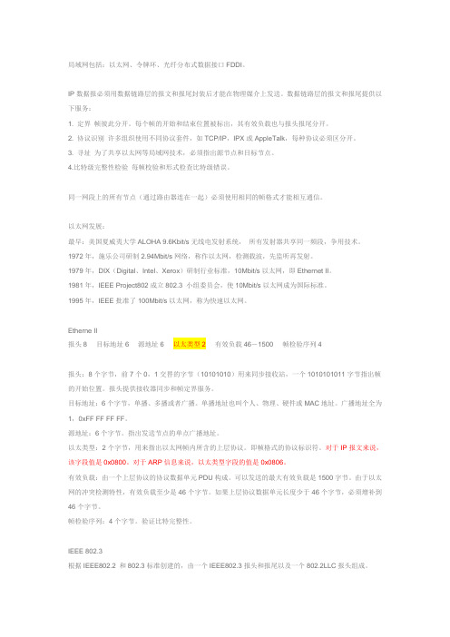
Etherne II报头8 目标地址6 源地址6 以太类型2 有效负载46-1500 帧检验序列4报头:8个字节,前7个0,1交替的字节(10101010)用来同步接收站,一个1010101011字节指出帧的开始位置。
报头提供接收器同步和帧定界服务。
目标地址:6个字节,单播、多播或者广播。
单播地址也叫个人、物理、硬件或MAC地址。
广播地址全为1,0xFF FF FF FF。
源地址:6个字节。
指出发送节点的单点广播地址。
以太类型:2个字节,用来指出以太网帧内所含的上层协议。
即帧格式的协议标识符。
对于IP报文来说,该字段值是0x0800。
对于ARP信息来说,以太类型字段的值是0x0806。
神州数码路由交换命令
特别注意交换机恢复出厂:set dfault write reloadfirewall enable#全局开启firewall enablefirewall default {permit | deny} 设置防火墙默认动作跟踪路由tracertTelnet,SSH远程登录路由器aaa authentication login default localaaa authentication enable default enableusername abc password 123enable password 0 123line vty 0login authentication default交换机Switch(config)# telnet-server enableSwitch(config)#username test privilege 15 password 0 testSwitch(config)#authentication line vty login localauthentication securityip <ip-addr> 配置Telnet登录到交换机的安全IP地址限制允许IP地址段Telnet登录交换机switch(config)#access-list1permit192.168.1.0 0.0.0.255switch(config)#authentication ip access-class 1 inSwitch(config)#ssh-server enableSwitch(config)#username test privilege 15 password 0 testSwitch(config)#authentication line vty login localSwitch(config)#interface vlan 1Switch(Config-if-Vlan1)#ip address 100.100.100.200 255.255.255.0ssh-server timeout <timeout> 设置SSH认证超时时间ssh-server authentication-retries <authentication-retires> 设置SSH认证重试次数switch(config)#ip http serverswitch(config)#username test privilege15password0 testswitch(config)#authentication line web login localswitch(config)#ip http secure-serverDHCPswitch(config)#service dhcpswitch(config)#ip dhcp pool vlan10switch(dhcp-vlan10-config)#network10.1.1.1 24switch(dhcp-vlan10-config)#default-router10.1.1.1中继:switch(config)#service dhcpswitch(config)#ip forward-protocol udp bootpsswitch(config-Vlan20)#ip help-address 10.1.1.1dhcp绑定,不允许手动配置ip地址#全局开启DHCP Snooping和DHCP Snooping绑定功能DHCP分配固定ip:switch(config)#ip dhcp excluded-address 10.1.1.2 10.1.1.10 不自动分配地址池switch(config)#ip dhcp pool 10switch(dhcp-vlan10-config)#host10.1.1.5switch(dhcp-vlan10-config)#default-router10.1.1.1switch(dhcp-vlan10-config)#hardware-address 00-0B-4C-9E-2a -1C绑定硬件地址#全局开启DHCP Snooping和DHCP Snooping绑定功能switch(config)#ip dhcp snooping enableswitch(config)#ip dhcp snooping binding enableswitch(config)#interface ethernet1/24switch(Config-Ethernet1/24)#ip dhcp snooping trust#设置E 1/1端口可以自动绑定DHCP获得的IP地址switch(config)#interface ethernet1/1switch(Config-Ethernet1/1)#ip dhcp snooping binding user-controlswitch(Config-Ethernet1/1)#exit#手动绑定PC 1的IP地址和MAC地址switch(config)#ip dhcp snooping binding user 00-11-11-11-11-11address 10.1.1.2mask 255.255.255.0vlan1interface 1/2路由器:Router_config#ip dhcpd enable //启动DHCP 服务Router_config#ip dhcpd pool 1Router_config_dhcp#network 192.168.1.0 255.255.255.0Router_config_dhcp#range 192.168.1.11 192.168.1.20Router_config_dhcp#lease 1 //定义租期Router_config_dhcp#dns-server 1.1.1.1 //定义DNS服务器地址Router_config_dhcp#default-router 192.168.1.1端口安全Switchport port-security lock 锁定安全端口,使pc只能通过此端口通信Switchport port-security convert 动态学习macMac-address-table blackhole address aa-bb-cc-dd-ee-ff vlan 30 mac表过滤端口操作端口IP mac绑定#全局打开AM功能Switch(config)#am enable#端口 1/1开启AM功能,绑定IPSwitch(config)#interface ethernet 1/1Switch(config-If-Ethernet 1/1)#am portSwitch(config-If-Ethernet 1/1)#am ip-pool 1.1.1.2 2Switch(config-If-Ethernet 1/1)#exit#端口 1/2开户AM功能,绑定IP、MACSwitch(config)#interface ethernet1/2Switch(config-If-Ethernet 1/2)#am portSwitch(config-If-Ethernet 1/2)#am mac-ip-pool00-44-44-44-44-44 1.1.1.4Switch(config-If-Ethernet 1/2)#exit端口限速Switch(config)#interface ethernet 1/1Switch(Config-If-Ethernet1/1)#bandwidth control10000both 限速10MB参数:both为端口收发时均进行带宽控制;receive为仅在端口接收数据时进行带宽控制;transmit为仅在端口发送数据时进行带宽控制。
新格林耐特配置命令
第一部分:TiNetS2000EI系列配置命令及说明(红色标识为一些常用命令)Username(1-32chars):adminPassword(1-16chars):******/登陆交换机,默认密码123456/TiNet>enable/进入特权模式/TiNet#configureterminal/进入全局模式/TiNet(config)#1.TINET#terminallanguage/改变语言模式/例如:TINET#terminallanguageChinese/改成中文模式/2.TiNet#clearstartup-config/清除配置,恢复出厂默设置/3.4.5./6.7.8.9./ 10.11.12./端口为trunk模式,允许所有VLAN通过/13.TiNet(config-if-ethernet-0/2)#switchportaccessvlan1001/改变端口PVID/14.TiNet(config)#port-isolationethernet?STRING<3-4>端口号为槽端口号<0-2>/端口号<1-24>TiNet(config)#port-isolationethernet0/2toe0/16添加端口隔离下行端口成功./一步隔离,一条命令隔离除上行口以外所有端口/15.TiNet(config)#interfacerangeethernet0/2toethernet0/16/批量端口处理命令/16.TiNet(config-if-range)#bandwidth-control?egress出口带宽控制ingress入口带宽控制/端口限速命令/17.TiNet(config)#showutilizationinterface/实时查看端口流量占比/LinkUtilizationAveragesThuJan100:43:201970portlinkReceivePeakRxTransmitPeakTxStatuspkts/secpkts/secpkts/secpkts/sec==================================================================e0/1down0000e0/2down0000e0/3down0000e0/4down0000e0/5down0000e0/6down000018.简要流程/配置ip地址/ConfigIPsuccessfully.TiNet(config)#showipSwitchconfigurationipobtained:MANUALnetmask:ManageVLAN:1MACaddress:00:0a:5a:11:ba:b8/查看交换机ip地址/TiNet(config)#exTiNet#terminallanguagechinese/更改语言模式为中文/TiNet(config)#vlan3901/建立vlan3901/TiNet(config-if-vlan)#switchportall/在vlan3901下添加端口/添加VLAN端口成功!TiNet(config)#ipaddressvlan3901/定义交换机管理vlan/配置管理VLAN成功!TiNet(config)#showip交换机的配置信息IP地址获得方式:MANUAL管理VLAN:13901/此时管理vlan为1和3901/MAC地址:00:0a:5a:11:ba:b8IP管理MAC添加显示添加TiNet(config-if-vlan)#showvlan1015显示VLAN信息VLANID:1015VLANstatus:staticVLANmember:e0/1,e0/16.Statictaggedports:StaticuntaggedPorts:e0/1,e0/16.Dynamictaggedports:TiNet(config)#port-isolationethernet0/2toe0/16/端口2-16进行隔离,1口为上行口,未隔离/添加端口隔离下行端口成功.TiNet(config-if-ethernet-0/1)#switchport?accessaccess端口backup配置备份端口mode端口模式trunktrunk端口TiNet(config-if-ethernet-0/1)#switchportmodetrunk/更改端口1模式为trunk/ TiNet(config-if-ethernet-0/1)#switchporttrunkallowedvlanall/允许所有vlan通过1口/ TiNet(config-if-ethernet-0/1)#switchporttrunknativevlan3901/更改1口pvid为3901/请输入您的登录密码:******请输入用户名(4--15位):admin请输入新口令(1--15位):******输入确认口令(1--15位):******/用户admin密码修改成功/ TiNet#copyrunning-configstartup-config/保存配置命令/第二部分:交换机实现telnet管理配置步骤第一步:配置规划好的交换机ip地址例:/配置ip地址/ConfigIPsuccessfully.TiNet(config)#showipSwitchconfigurationipobtained:MANUALManageVLAN:1MACaddress:00:0a:5a:11:ba:b8/查看交换机ip地址/第二步:建立规划好的管理vlan,把上行口加入到管理vlan中,然后删除默认的管理vlan1 例:TiNet(config)#vlan3901/建立vlan3901/TiNet(config-if-vlan)#switchporte0/1/在vlan3901中添加端口1/添加VLAN端口成功!IP管理MAC例:。
Ethernet和Internet的区别是什么
1.Ethernet和Internet的区别是什么?以太网(Ethernet)是一种计算机局域网组网技术。
IEEE(电气和电子工程师协会)制定的IEEE 802.3标准给出了以太网的技术标准。
它规定了包括物理层的连线、电信号和介质访问层协议的内容。
以太网是当前应用最普遍的局域网技术。
它很大程度上取代了其他局域网标准,如令牌环、FDDI和ARCNET。
以太网的标准拓扑结构为总线型拓扑,但目前的快速以太网(100BASE-T、1000BASE-T标准)为了最大程度的减少冲突,最大程度的提高网络速度和使用效率,使用交换机(Switch)来进行网络连接和组织,这样,以太网的拓扑结构就成了星型,但在逻辑上,以太网仍然使用总线型拓扑的CSMA/CD介质访问控制方法。
历史:以太网是由日本施乐公司与DEC和Intel公司于1980年合作开发的一个局域网协议。
Internet是将以往相互独立的,散落在各个地方的单独的计算机或是相对独立的计算机局域网,借助已经发展得有相当规模的电信网络,通过一定的通讯协议而实现更高层次的互联。
在这个互联网络中,一些超级的服务器通过高速的主干网络(光缆,微波和卫星)相连,而一些较小规模的网络则通过众多的支干与这些巨型服务器连接。
在这些连接中,包括:物理连接和软件连接。
所谓物理连接就是,各主机之间的连接利用常规电话线,高速数据线,卫星,微波或光纤等各种通信手段。
那么软件连接是什么呢?是全球网络中的电脑使用同一种语言进行交流。
换句话说,就是使用相同的通讯协议2.Ethernet IP和profinet的区别EtherCAT(以太网控制自动化技术)是一个以以太网为基础的开放架构的现场总线系统,EterCAT名称中的CAT为Control Automation Technology(控制自动化技术)首字母的缩写。
最初由德国倍福自动化有限公司(Beckhoff Automation GmbH)研发。
华为_华三交换机混合(hybrid)接口配置详解
交换机的端口加入vlan有三种方式,分别是access、trunk和hybrid。
1、access端口只能加入一个vlan,一般用来连接交换机和pc,也可以连接交换机和交换机。
2、trunk端口可以加入多个vlan,就是说可以允许多个vlan的报文通过。
trunk 端口有一个默认vlan,如果收到的报文没有vlan ID,就把这个报文当做默认vlan的报文处理。
trunk口一般用于连接两台交换机,这样可以只用一条trunk 连接实现多个vlan的扩展(因为trunk允许多个vlan的数据通过,如果用access 口,那么一个vlan就要一条连接,多个vlan要多个连接,而交换机的接口是有限的)。
对于trunk口发送出去的报文,只有默认vlan的报文不带vlan ID,其它vlan的报文都要带vlan ID(要不然,对端的交换机不知道该报文属于哪个vlan,无法处理,也就不能实现vlan跨交换机扩展了)。
简而言之,trunk 端口的设计目的就是通过一条连接实现多个vlan的跨交换机扩展。
3、trunk端口是hybrid端口的特例,就是说hybrid端口可以实现比trunk端口更多的功能。
hybrid端口可以加入多个vlan,并可以设置该vlan的报文通过该端口发送是是否带vlan ID(trunk端口不能设置,只有默认vlan的报文不带vlan ID进行发送)。
通过下面的两个例子(转载的),大家应该可以看出hybrid 端口的设计目的。
例一:『配置环境参数』1. PC1、PC2和PC3分别连接到二层交换机SwitchA的端口E0/1 、E0/2和 E0/3,端口分属于VLAN10、20和30,服务器连接到端口G2/1,属于VLAN100。
2. PC1的IP地址为10.1.1.1/24,PC2的IP地址为10.1.1.2/24,PC3的IP地址为10.1.1.3/24,服务器的IP地址为10.1.1.254/24。
交换机端口untaged、taged、trunk、access 的区别
交换机端口untaged、taged、trunk、access 的区别分类:系统运维来源:网络首先,将交换机的类型进行划分,交换机分为低端(SOHO级)和高端(企业级)。
其两者的重要区别就是低端的交换机,每一个物理端口为一个逻辑端口,而高端交换机则是将多个物理端口捆绑成一个逻辑端口再进行的配置的。
cisco网络中,交换机在局域网中最终稳定状态的接口类型主要有四种:access/ trunk/ multi/ dot1q-tunnel。
1、access: 主要用来接入终端设备,如PC机、服务器、打印服务器等。
2、trunk: 主要用在连接其它交换机,以便在线路上承载多个vlan。
3、multi: 在一个线路中承载多个vlan,但不像trunk,它不对承载的数据打标签。
主要用于接入支持多vlan的服务器或者一些网络分析设备。
现在基本不使用此类接口,在cisco的网络设备中,也基本不支持此类接口了。
4、dot1q-tunnel: 用在Q-in-Q隧道配置中。
Cisco网络设备支持动态协商端口的工作状态,这为网络设备的实施提供了一定的方便(但不建议使用动态方式)。
cisco动态协商协议从最初的DISL(Cisco私有协议)发展到DTP(公有协议)。
根据动态协议的实现方式,Cisco网络设备接口主要分为下面几种模式:1、switchport mode access: 强制接口成为access接口,并且可以与对方主动进行协商,诱使对方成为access模式。
2、switchport mode dynamic desirable: 主动与对协商成为Trunk接口的可能性,如果邻居接口模式为Trunk/desirable/auto之一,则接口将变成trunk接口工作。
如果不能形成trunk 模式,则工作在access模式。
这种模式是现在交换机的默认模式。
3、switchport mode dynamic auto: 只有邻居交换机主动与自己协商时才会变成Trunk接口,所以它是一种被动模式,当邻居接口为Trunk/desirable之一时,才会成为Trunk。
Ubuntu网络配置
Ubuntu⽹络配置修改主机名root@ubuntu1804:~# hostnamectl set-hostname ubuntu1804.longxuan.toproot@ubuntu1804:~# cat /etc/hostnameubuntu1804.longxuan.toproot@ubuntu1804:~# hostnameubuntu1804.longxuan.toproot@ubuntu1804:~# echo $HOSTNAMEubuntu1804root@ubuntu1804:~# exitlogoutwang@ubuntu1804:~$ sudo -iroot@ubuntu1804:~# echo $HOSTNAMEubuntu1804.longxuan.top修改⽹卡名称为传统命名⽅式:#修改配置⽂件为下⾯形式root@ubuntu1804:~# vi /etc/default/grubGRUB_CMDLINE_LINUX="net.ifnames=0"#或者sed修改root@ubuntu1804:~# sed -i.bak '/^GRUB_CMDLINE_LINUX=/s#"$#net.ifnames=0"#'/etc/default/grub#⽣效新的grub.cfg⽂件root@ubuntu1804:~# grub-mkconfig -o /boot/grub/grub.cfg#或者root@ubuntu1804:~# update-grubroot@ubuntu1804:~# grep net.ifnames /boot/grub/grub.cfg#重启⽣效root@ubuntu1804:~# rebootUbuntu⽹卡配置官⽹⽂档:https:///https:///server/docs/network-configuration配置⾃动获取IP⽹卡配置⽂件采⽤YAML格式,必须以/etc/netplan/XXX.yaml ⽂件命名⽅式存放可以每个⽹卡对应⼀个单独的配置⽂件,也可以将所有⽹卡都放在⼀个配置⽂件⾥范例:root@ubuntu1804:~# cat /etc/netplan/01-netcfg.yaml# This file describes the network interfaces available on your system# For more information, see netplan(5).network:version: 2renderer: networkdethernets:eth0:dhcp4: yes配置静态IProot@ubuntu1804:~# vim /etc/netplan/01-netcfg.yamlnetwork:version: 2renderer: networkdethernets:eth0:addresses: [172.31.0.19/16,10.0.0.10/8] #或者⽤下⾯两⾏,两种格式不能混⽤- 172.31.0.19/16- 10.0.0.10/8gateway4: 10.0.0.254nameservers:search: [, longxuan.top]addresses: [180.76.76.76, 8.8.8.8, 1.1.1.1]查看ip和gatewayroot@ubuntu1804:~# ip addrroot@ubuntu1804:~# route -n查看DNSroot@ubuntu1804:~# ls -l /etc/resolv.conflrwxrwxrwx 1 root root 39 Dec 12 11:36 /etc/resolv.conf ->../run/systemd/resolve/stub-resolv.confroot@ubuntu2004:~# resolvectl status #Ubuntu 20.04新命令root@ubuntu1804:~# systemd-resolve --statusGlobalDNSSEC NTA: 10.in-addr.arpa...MulticastDNS setting: noDNSSEC setting: noDNSSEC supported: noDNS Servers: 180.76.76.768.8.8.81.1.1.1DNS Domain: longxuan.top配置多⽹卡静态IP和静态路由root@ubuntu1804:~# vim /etc/netplan/01-netcfg.yaml# This file describes the network interfaces available on your system # For more information, see netplan(5).network:version: 2renderer: networkdethernets:eth0:dhcp4: nodhcp6: noaddresses: [172.31.0.19/16]gateway4: 172.31.0.254nameservers:addresses: [223.6.6.6]eth1:dhcp4: nodhcp6: noaddresses: [172.31.8.20/16]routes:- to: 172.31.0.0/16via: 172.31.0.1- to: 10.40.0.0/16via: 10.20.0.1- to: 10.50.0.0/16via: 10.20.0.1- to: 10.60.0.0/16via: 10.20.0.1root@ubuntu1804:~# netplan apply#或者每个⽹卡各⾃⼀个配置⽂件root@ubuntu1804:/etc/netplan# ls01-netcfg.yaml 02-eth1.yamlroot@ubuntu1804:/etc/netplan# cat 01-netcfg.yaml# This file describes the network interfaces available on your system # For more information, see netplan(5).network:version: 2renderer: networkdethernets:eth0:dhcp4: yesroot@ubuntu1804:/etc/netplan# cat 02-eth1.yamlnetwork:version: 2renderer: networkdethernets:eth1:addresses:- 172.31.0.19/16- 192.168.0.100/24gateway4: 172.31.0.254nameservers:search: [, longxuan.tcp]addresses: [180.76.76.76, 8.8.8.8, 1.1.1.1]routes:- to: 172.31.0.0/16via: 172.31.0.1- to: 10.40.0.0/16via: 10.20.0.1- to: 10.50.0.0/16via: 10.20.0.1- to: 10.60.0.0/16via: 10.20.0.1单⽹卡桥接root@ubuntu1804:~# apt install -y bridge-utilsroot@ubuntu1804:~# dpkg -L bridge-utils/sbin/brctl......#三个⽹卡配置使⽤⼀个配置⽂件root@ubuntu1804:~# cat /etc/netplan/50-cloud-init.yaml# This file describes the network interfaces available on your system # For more information, see netplan(5).network:version: 2renderer: networkdethernets:eth0:dhcp4: yeseth1:dhcp4: nodhcp6: noeth2:dhcp4: nobridges:br0:dhcp4: nodhcp6: noaddresses: [172.31.0.19/16]gateway4: 1072.31.0.254nameservers:addresses: [223.6.6.6]interfaces:- eth1- eth2#桥接配置单独⼀个⽂件[root@ubuntu1804 netplan]# vim /etc/netplan/br0.yamlnetwork:version: 2renderer: networkdethernets:eth1:dhcp4: nodhcp6: noeth2:dhcp4: nobridges:br0:dhcp4: nodhcp6: noaddresses: [172.31.0.10/16]gateway4: 172.31.0.254nameservers:addresses: [223.6.6.6]interfaces:- eth1- eth2root@ubuntu1804:~# netplan applyroot@ubuntu1804:~# ifconfig br0root@ubuntu1804:~# brctl showbridge name bridge id STP enabled interfacesbr0 8000.9ebe1d856601 no eth1eth2多⽹卡桥接#有多少个eth 就要有多少块⽹卡root@ubuntu1804:~# vim /etc/netplan/50-cloud-init.yaml# This file describes the network interfaces available on your system # For more information, see netplan(5).network:version: 2renderer: networkdethernets:eth0:dhcp4: nodhcp6: noeth1:dhcp4: nodhcp6: nobridges:addresses: [172.31.0.19/16]gateway4: 172.31.0.254nameservers:addresses: [223.6.6.6]interfaces:- eth0br1:dhcp4: nodhcp6: noaddresses: [172.31.0.19/16]routes:- to: 172.31.0.0/16via: 172.31.0.1- to: 10.30.0.0/16via: 10.10.0.1- to: 10.4.0.0/16via: 10.10.0.1- to: 10.50.0.0/16via: 10.10.0.1interfaces:- eth1root@ubuntu1804:~# netplan applyroot@ubuntu1804:~# brctl showbridge name bridge id STP enabled interfacesbr0 8000.96dbd15c1daf no eth0br1 8000.9e02ab0faeb0 no eth1root@ubuntu1804:~# ifconfig br0br0: flags=4163<UP,BROADCAST,RUNNING,MULTICAST> mtu 1500inet 172.31.0.18 netmask 255.255.0.0 broadcast 172.31.255.255root@ubuntu1804:~# ifconfig br1br1: flags=4163<UP,BROADCAST,RUNNING,MULTICAST> mtu 1500inet 172.31.0.18 netmask 255.255.0.0 broadcast 172.31.255.255双⽹卡绑定⽀持多⽹卡绑定七种模式第⼀种模式:mod=0,即:(balance-rr) Round-robin policy(平衡抡循环策略)特点:传输数据包顺序是依次传输(即:第1个包⾛eth0,下⼀个包就⾛eth1...⼀直循环下去,直到最后⼀个传输完毕),此模式提供负载平衡和容错能⼒。
- 1、下载文档前请自行甄别文档内容的完整性,平台不提供额外的编辑、内容补充、找答案等附加服务。
- 2、"仅部分预览"的文档,不可在线预览部分如存在完整性等问题,可反馈申请退款(可完整预览的文档不适用该条件!)。
- 3、如文档侵犯您的权益,请联系客服反馈,我们会尽快为您处理(人工客服工作时间:9:00-18:30)。
PIC3102 23PFBOUTPIC30 1 0.1uF should be placed close to the COC32 C32 23PFBOUT PFBOUT pin, and0.1 μF caps 0.1uF should be placed close to the 18PFBIN1 PFBIN1 and PFBIN2 pins.
PIR1 01
VDD
36 35 34 33 32 31 30 29 28 27 26 25
COU2 U2
DP83848I B
PIU2036 PIU2035 PIU2034 PIU203 PIU2032 PIU2031 PIU203 PIU20 9 PIU20 8 PIU20 7 PIU20 6 PIU20 5
画原理图的在差分线命名时采用(N,P)(+,-) 差分对网络名称必须以?_N? 和?_P? 作为后辍。 对差分网络放置指令后要对其参数进行配置, 包括DifferentialPair名称以及True参数
VDD
PIC3 02 PIC3201 COC33 C33 0.1uF PIC3 01 37PFBIN2
Asserting this pin low for at least 1 μs will force a reset process to occur. VDD
COC30 C30 parallel with a 0.1 μF cap
A 10.0 μF tantalum capacitor in
C
1 2 3 4 5 6 7 8 9 10 11 12
1
2
3
4
VDD
PIR602
COR6 R6
1.5K
PIR601
NLMDIO MDIO
NLRD0P RD_P
PIR701 PIR702
A
39上拉,6不接,使用RMII 40上拉,LED选择MODE 1 41不接下拉,使用默认enable MDIX 30需要一个1.5K的上拉电阻
VDD
VDD COR7 R7 49.9/1%
PIC3702 PIC3701
GND
D
Title
D Number Revision
Size A4 Date: File: 1 2 3
2014/4/25 Sheet of E:\STM32F407ZE+3SPI\..\02_Ethernet.SchDoc Drawn By: 4
A
Байду номын сангаас
COR9 220 PIR902 VDD NLLED0LNK 10 LED_LNK PICN1010
9 PIR901 R9 PICN109
GND
MDIO RESET_N LED_LNK
LED_ACT
POPA20RMII0MDIO PA2_RMII_MDIO POPC10RMII0MDC PC1_RMII_MDC POPA10RMII0CLK PA1_RMII_CLK
DGND IOGND X1 X2 IOVDD33 MDC MDIO RESET_N LED_LINK/AN0 LED_SPEED/AN1 LED_ACT/COL/AN_EN 25MHz_OUT
PIR1 02 PIR1202
COR11 R11 49.9/1%
VDD
COC28 C28 0.1uF
2 TD4 TCT 1 PICN101 TD+
COX3 X3 50M NLCLK 4 3 CLK PIX304 VDD CLK PIX303
PIX301
PIR802
NLRD0N RD_N
1
NC
GND
PIX302
2
GND
PIR801
0.1uF COR8 R8 49.9/1% GND DP83848
PIC2602 PIC2601
VDD
GND
COC26 C26
VDD
37 38 PIU2038 39 PIU2039 40 PIU2040 41 PIU2041 42 PIU2042 43 PIU2043 44 PIU2044 45 PIU2045 46 PIU2046 47 PIU2047 48 PIU2048
PIU2037
PFBIN2 RX_CLK RX_DV/MII_MODE CRS/CRS_DV/LED_CFG RX_ER/MDIX_EN COL/PHYAD0 RXD_0/PHYAD1 RXD_1/PHYAD2 RXD_2/PHYAD3 RXD_3/PHYAD4 IOGND IOVDD33
RBIAS PFBOUT AVDD33 RESERVED RESERVED AGND PFBIN1 TD+ TDAGND RD+ RD-
24必须用4.87K电阻连接到GND COR13 4.87K/1% 24 R13 PIU2024 PIR1301 PIR1302
23 PIU2023 22 PIU2022 21 PIU2021 20 PIU2020 19 PIU2019 18 PIU2018 17 PIU2017 16 PIU2016 15 PIU2015 14 PIU2014 13 PIU2013 PFBOUT
1 PIRS101 POPA70RMII0CRS0DV PA7_RMII_CRS_DV 3 PIRS103 PC4_RMII_RXD_0 POPC40RMII0RXD00 5 PIRS105 POPC50RMII0RXD01 PC5_RMII_RXD_1 7 PIRS107 RXDV,RX0,RX1是PHY到 MAC,33欧姆串行电阻放在 输出端,即紧靠DP83848GND 33
B
HR911105A GND
GND
COR16 R16 COR17 R17
2.2K PIR1601 2.2K PIR1701
VDD VDD 20,,21不使用,必须用2.2K上拉到高 GND
NLPFBOUT PFBOUT
PFBOUT TD_N TD_P RD_N RD_P
PIC3101 PIC3202
2 4 PIRS204 6 PIRS206 8 PIRS208
PIRS202
7脚是低功耗控制或者中断,该引脚默认内部上拉, 即默认该引脚是低功耗控制模式,当有一个低电平 输入时就会触发低功耗模式。这里空置,不使用 不需要使用JATG,引脚8-12空着
PIC3402 PIC3401
COC34 C34 0.1uF
PIR1602 PIR1702
NLTD0N TD_N
PIR1201
COC29 C29 0.1uF COR12 R12 49.9/1% GND
PIC2902 PIC2901
7 NC 8 PICN108 CHS GND
PICN107
13 PICN1013 14 PICN1014
Shield Shield
The device Vdd supply pins should be bypassed with low impedance 0.1 μF surface mountcapacitors.To reduce EMI,the capacitors should be places as close aspossible to the component Vdd supply pins
PIR1402 PIR1501
COR14 R14 2.2K PIR1401 COR15 R15 2.2K PIR1502
CORS1 RS1
2 4 PIRS104 6 PIRS106 8 PIRS108
PIRS102
TX_CLK TX_EN TXD_0 TXD_1 TXD_2 TXD_3/SNI_MODE PWR_DOWN/INT TCK TDO TMS TRST# TDI
COC31 C31 10uF
PIC30 2
GND
Phy Address Straps: Default is PHYAD0 = 1 C
PIU201 PIU20 PIU203 PIU204 PIU205 PIU206 PIU207 PIU208 PIU209 PIU201 PIU201 PIU2012
PIC3502 PIC3501
COC35 C35 0.1uF
PIC3602 PIC3601
COC36 C36
0.1uF SW2 COSW2
PISW201
PIR1802 PIR1801
PISW202
R18 COR18 10K RESET_N NLRESET0N C37 COC37 0.1uF
GND
TXEN,TX0,TX1是MAC到 PHY,33欧姆串行电阻放在 输出端,即紧靠MAC
22/31/42旁边需要放置一个电容 5脚不用,6脚使用内部下拉即0,配合39的1,使用RMII
RS2 CORS2 1 PB11_RMII_TX_EN PIRS201 POPB110RMII0TX0EN 3 PIRS203 PB12_RMII_TXD_0 POPB120RMII0TXD00 5 PIRS205 PB13_RMII_TXD_1 POPB130RMII0TXD01 7 PIRS207 33
PICN102 PICN104
LED(Y)+ LED(Y)-
PICN1012 PIR1001
COR10 220 12 R10 PIR1002
VDD
NLLED0ACT 11 LED_ACT PICN1011
40脚内部上拉,即1,灯使用默认的模式1 40脚内部上拉,即1,灯使用默认的模式1
PFBOUT VDD
PIC2702 PIC2701
COCN1 CN1 COC27 C27 0.1uF
6 PICN106 RD5 PICN105 RCT 3 PICN103 RD+
