uartlite资料2
UART串口协议详解
UART串口协议详解通用异步(Universal Asynchronous Receiver/Transmitter),通常称作UART,是一种串行、异步、全双工的通信协议,在领域应用的十分广泛。
UART作为异步串行通信协议的一种,工作原理是将传输数据的每个二进制位一位接一位地传输。
在UART通信协议中信号线上的状态为高电平常代表‘1’,信号线上的状态为低电平常代表‘0’。
比如用法UART 通信协议举行一个字节数据的传输时就是在信号线上产生八个凹凸电平的组合。
但事实上UART通信协议在举行一个字节的数据传输时除了最基本的数据位之外还有许多其他的信息需要表示,详细的协议格式如下空闲位:UART协议规定,当处于空闲状态时信号线的状态为‘1’即高电平起始位:每开头一次通信时发送方先发出一个规律”0”的信号(低电平),表示传输字符的开头。
由于总线空闲时为高电平所以开头一次通信时先发送一个显然区分于空闲状态的信号即低电平。
数据位:起始位之后就是我们所要传输的数据,数据位可以是5、6、7、8位等,构成一个字符。
先发送最低位,最后发送最高位,用法低电平表示‘0’高电平表示‘1’完成数据位的传输。
奇偶校验位:数据位加上这一位后,使得“1”的位数应为偶数(偶校验)或奇数(奇校验),以此来校验数据传送的正确性停止位:它是一个字符数据的结束标记。
可以是1位、1.5位、2位的高电平。
因为数据是在传输线上定时的,并且每一个设备有其自己的时钟,很可能在通信中两台设备之间浮现了小小的不同步。
因此停止位不仅仅是表示传输的结束,并且提供计算机校正时钟的机会。
停止位个数越多,数据传输越稳定,但是数据传输速度也越慢。
比特率:在UART中用法波特率来表示数据的传输速度。
比特率是表示每秒钟传送的二进制位的个数。
2_UART
NUC100
IrDA模式(2/2) IrDA模式(2/2)
LIN模式 LIN模式
支持 LIN break 域和break 长度设定. 在LIN Rx模式, 支持break 域中断
UART中断 UART中断
UART中断源
Receive Data Available Interrupt (Select RFITL to set trigger level) Transmit Holding Register Empty Interrupt Rx Timeout Interrupt Buffer Error Interrupt
UART时序设定(2/2) UART时序设定(2/2)
System clock = 22.1184Mhz Baud rate 921600 460800 230400 115200 57600 38400 19200 9600 4800 Mode0 x A=1 A=4 A=10 A=22 A=34 A=70 A=142 A=286 Mode1
每个通道有单独·的可编程波特率发生器.
Mode Mode 0 Mode 1 Mode 2
DIV_X_EN Disable Enable Enable
DIV_X_ONE 0 0 1
Divider X B B B
BRD A A A
Baud3;2)] UART_CLK / [(B+1) * (A+2)] , B must >= 8 UART_CLK / (A+2), A must >=3
Mode2 A=22 A=46 A=94 A=190 A=382 A=574 A=1150 A=2302 A=4606
UART自动流控功能 UART自动流控功能
ADZS-BF609-EZLITE;ADZS-BF609-EZBRD;中文规格书,Datasheet资料
ADSP-BF609 EZ-KIT Lite®Evaluation System ManualRevision 1.0, March 2012Part Number82-000269-01 Analog Devices, Inc.One T echnology WayaNorwood, Mass. 02062-9106Copyright Information© 2012 Analog Devices, Inc., ALL RIGHTS RESERVED. This docu-ment may not be reproduced in any form without prior, express writtenconsent from Analog Devices, Inc.Printed in the USA.DisclaimerAnalog Devices, Inc. reserves the right to change this product withoutprior notice. Information furnished by Analog Devices is believed to beaccurate and reliable. However, no responsibility is assumed by AnalogDevices for its use; nor for any infringement of patents or other rights ofthird parties which may result from its use. No license is granted by impli-cation or otherwise under the patent rights of Analog Devices, Inc. Trademark and Service Mark NoticeThe Analog Devices logo, Blackfin, CrossCore, EZ-Board, EZ-Extender, and EZ-KIT Lite are registered trademarks of Analog Devices, Inc.All other brand and product names are trademarks or service marks oftheir respective owners.Regulatory ComplianceThe ADSP-BF609 EZ-KIT Lite is designed to be used solely in a labora-tory environment. The board is not intended for use as a consumer end product or as a portion of a consumer end product. The board is an open system design which does not include a shielded enclosure and therefore may cause interference to other electrical devices in close proximity. This board should not be used in or near any medical equipment or RF devices.The ADSP-BF609 EZ-KIT Lite is currently being processed for certifica-tion that it complies with the essential requirements of the EuropeanEMC directive 2004/108/EC and therefore carries the “CE” mark.The EZ-KIT Lite evaluation system contains ESD (electrostatic discharge)sensitive devices. Electrostatic charges readily accumulate on the humanbody and equipment and can discharge without detection. Permanent dam-age may occur on devices subjected to high-energy discharges. Proper ESDprecautions are recommended to avoid performance degradation or loss offunctionality. Store unused EZ-KIT Lite boards in the protective shippingpackage.PREFACEProduct Overview (xii)Purpose of This Manual (xv)Intended Audience (xv)Manual Contents (xvi)What’s New in This Manual (xvi)Technical or Customer Support (xvii)Supported Processors (xvii)Product Information (xviii)Analog Devices Web Site (xviii)EngineerZone (xviii)Related Documents (xix)Notation Conventions (xx)USING ADSP-BF609 EZ-KIT LITEPackage Contents .......................................................................... 1-2 ADSP-BF609 EZ-Board ................................................................ 1-3 Default Configuration ................................................................... 1-3 Supported Operating Systems ....................................................... 1-5ADSP-BF609 EZ-KIT Lite Evaluation System Manual vSystem Requirements .................................................................... 1-5 EZ-KIT Lite Installation ............................................................... 1-6 EZ-KIT Lite Session Startup ......................................................... 1-7 Evaluation License Restrictions ................................................... 1-10 Memory Map ............................................................................. 1-10 DDR2 SDRAM .......................................................................... 1-12 SPI Interface .............................................................................. 1-13 SMC Interface ............................................................................ 1-13 Ethernet Interface ....................................................................... 1-13 USB OTG HS Interface .............................................................. 1-14 CAN Interface ............................................................................ 1-14 UART Interface .......................................................................... 1-15 SD Interface ............................................................................... 1-16 Rotary Encoder Interface ............................................................ 1-16 Temperature Sensor Interface ...................................................... 1-17 Link Ports Interface .................................................................... 1-17 General-Purpose I/O (GPIO) ...................................................... 1-18 JTAG Interface ........................................................................... 1-18 Power-On-Self Test ..................................................................... 1-20 Expansion Interface III ............................................................... 1-20 Power Architecture ..................................................................... 1-21 Power Measurements .................................................................. 1-21 Example Programs ...................................................................... 1-22 Reference Design Information ..................................................... 1-22vi ADSP-BF609 EZ-KIT Lite Evaluation System ManualADSP-BF609 EZ-KIT LITE HARDWARE REFERENCE System Architecture ...................................................................... 2-2 Software-Controlled Switches (SoftConfig) .................................... 2-3 Overview of SoftConfig ........................................................... 2-3SoftConfig on the ADSP-BF609 EZ-KIT LITE ...................... 2-7Programming SoftConfig Switches ........................................... 2-8 Push Buttons and Switches .......................................................... 2-17 JTAG Interface Switches (SW1, SW3–5) ................................ 2-18Boot Mode Select Switch (SW2) ............................................ 2-19IRQ/Flag Enable Switches (SW6–7) ....................................... 2-20Reset Switch (SW8) ............................................................... 2-20Rotary Encoder With Momentary Switch (SW9) .................... 2-20Wake Push Switch (SW10) .................................................... 2-21 Power Jumpers ............................................................................ 2-21 LEDs .......................................................................................... 2-22 GPIO LEDs (LED1–4) ......................................................... 2-23Thermal Limit LED (LED5) ................................................. 2-23Power LED (LED6) ............................................................... 2-23Reset LED (LED7) ................................................................ 2-24SPD LED (LED6) ................................................................. 2-24 Connectors ................................................................................. 2-24 DCE UART Connector (J2) .................................................. 2-25Link Port /JTAG Connectors (J3 and P8) ............................... 2-25JTAG Connector (P1) ........................................................... 2-25 ADSP-BF609 EZ-KIT Lite Evaluation System Manual viiJTAG Connector (ZP1) ......................................................... 2-26Expansion Interface III Connectors (P1A–C, P2A, P3A) ........ 2-26USB Connector (P7) ............................................................. 2-26Power Connector (P18) ......................................................... 2-26CAN Connector (J4) ............................................................ 2-27SD Connector (J5) ................................................................ 2-27Ethernet Connector (J1) ....................................................... 2-27Ethernet Connectors (P16-17) ............................................... 2-27 ADSP-BF609 EZ-KIT LITE BILL OF MATERIALSADSP-BF609 EZ-KIT LITE SCHEMATICTitle Page ..................................................................................... B-1 Processor DDR2 Interface ............................................................ B-2 Processor Signals ........................................................................... B-3 Processor Power and Ground ......................................................... B-4 Temp Sensor, Boot Switch, DSP CLK, USB Conn ......................... B-5 Memory ....................................................................................... B-6 UART0 ........................................................................................ B-7 CAN and Rotary Encoder ............................................................. B-8 Ethernet ....................................................................................... B-9JTAG, Link Port 0 and 1 ........................................................... B-10 Push Buttons, Reset, LEDs ......................................................... B-11 SoftConfig Switches, IO Extender ICs ......................................... B-12 Expansion Interface, Page 1 ........................................................ B-13viii ADSP-BF609 EZ-KIT Lite Evaluation System ManualExpansion Interface, Page 2 ........................................................ B-14 Expansion Interface, Page 3 ........................................................ B-15 Power ........................................................................................ B-16 INDEXADSP-BF609 EZ-KIT Lite Evaluation System Manual ixx ADSP-BF609 EZ-KIT Lite Evaluation System Manual分销商库存信息: ANALOG-DEVICESADZS-BF609-EZLITE ADZS-BF609-EZBRD。
UART(中文版的数据手册)

UART(中⽂版的数据⼿册)第⼗⼀章异步串⼝通信概述S3C2410的UART提供3个独⽴的异步串⾏通信端⼝,每个端⼝可以基于中断或者DMA进⾏操作。
换句话说,UART控制器可以在CPU和UART之间产⽣⼀个中断或者DMA请求来传输数据。
UART在系统时钟下运⾏可⽀持⾼达230.4K 的波特率,如果使⽤外部设备提供的UEXTCLK,UART的速度还可以更⾼。
每个UART通道各含有两个16位的接收和发送FIFO。
S3C2410的UART包括可编程的波特率,红外接收/发送,⼀个或两个停⽌位插⼊,5-8位数据宽度和奇偶校验。
每个UART包括⼀个波特率发⽣器、⼀个发送器、⼀个接收器和⼀个控制单元,如图11-1所⽰。
波特率发⽣器的输⼊可以是PCLK或者UEXTCLK。
发送器和接收器包含16位的FIFO和移位寄存器,数据被送⼊FIFO,然后被复制到发送移位寄存器准备发送,然后数据按位从发送数据引脚TxDn输出。
同时,接收数据从接收数据引脚RxDn按位移⼊接收移位寄存器,并复制到FIFO。
特性—RxD0, TxD0, RxD1, TxD1, RxD2, 和TxD2基于中断或者DMA操作—UART Ch 0, 1, 和 2 具有 IrDA 1.0 & 16 字节 FIFO—UART Ch 0 和 1 具有 nRTS0, nCTS0, nRTS1, 和 nCTS1—⽀持发⽣/接收握⼿图11-1 UART⽅框图串⼝操作下述部分描述了UART的⼀些操作,包括数据发送、数据接收、中断产⽣、波特率发⽣、loop-back模式、红外模式和⾃动流控制。
数据发送发送数据的帧结构是可编程的,它由1个起始位、5-8个数据位、1个可选的奇偶位和1-2个停⽌位组成,这些可以在线控制寄存器ULCONn中设定。
接收器可以产⽣⼀个断点条件——使串⾏输出保持1帧发送时间的逻辑0状态。
当前发送字被完全发送出去后,这个断点信号随后发送。
断点信号发送之后,继续发送数据到Tx FIFO(如果没有FIFO则发送到Tx保持寄存器)。
UART协议

UART协议协议名称:UART协议一、引言UART(通用异步收发传输)协议是一种常用的串行通信协议,用于在计算机系统和外设之间进行数据传输。
本协议旨在规范UART通信的数据格式、传输速率、错误检测和控制流程等方面的要求,以确保数据的可靠传输和正确解析。
二、协议规范1. 数据格式1.1 数据位:UART协议支持的数据位数为5、6、7和8位。
1.2 停止位:UART协议支持的停止位数为1和2位。
1.3 校验位:UART协议支持的校验位类型包括无校验、奇校验和偶校验。
2. 传输速率2.1 波特率:UART协议支持的波特率范围为110bps至115200bps。
2.2 时钟源:UART协议使用内部或外部时钟源来生成传输时钟。
3. 错误检测3.1 奇偶校验:当启用校验位时,UART协议使用奇偶校验来检测数据传输过程中的错误。
3.2 帧错误:UART协议通过检测起始位和停止位之间的数据位数来判断数据帧是否接收正确。
3.3 奇偶校验错误:UART协议通过检测校验位的奇偶性来判断数据传输过程中是否发生了错误。
4. 控制流程4.1 RTS/CTS流控制:UART协议支持使用RTS(请求发送)和CTS(清除发送)信号进行硬件流控制。
4.2 XON/XOFF流控制:UART协议支持使用XON(发送继续)和XOFF (发送停止)字符进行软件流控制。
5. 数据传输5.1 数据帧:UART协议的数据传输以数据帧的形式进行,每个数据帧包含起始位、数据位、校验位和停止位。
5.2 起始位和停止位:UART协议使用起始位和停止位来标识数据帧的开始和结束。
5.3 数据传输顺序:UART协议按照先发送先接收的顺序进行数据传输。
5.4 数据传输模式:UART协议支持全双工和半双工两种数据传输模式。
6. 数据解析6.1 数据解析规则:UART协议中的数据解析规则由具体的应用决定,通常使用固定长度或特定字符进行分割和解析。
6.2 数据解析错误处理:UART协议中的数据解析错误应由接收方进行处理,例如丢弃错误的数据帧或发送错误消息。
uart对应标准与工作原理

uart对应标准与工作原理UART(Universal Asynchronous Receiver Transmitter),通用异步收发器,是一种用于串行通信的通信协议和硬件接口。
它是一种简单、常用的串行通信协议,被广泛应用在各种计算机和嵌入式系统中。
UART的工作原理如下:1. 串行数据传输:UART通过将数据位按顺序传输来进行串行通信。
每个数据位传输完成后,UART会传输下一个数据位,直至传输完整个数据字节。
2. 异步通信:UART采用异步通信方式,发送和接收数据时不需要时钟信号,而是通过发送和接收的数据位之间的间隔时间来同步数据。
这种异步通信方式不会受到发送和接收数据的时钟频率不同的限制。
3. 起始位和停止位:UART在每个数据字节的开始位置插入一个起始位(一般为低电平),以标识数据传输的开始。
在每个数据字节的结束位置插入一个或多个停止位(一般为高电平),以标识数据传输的结束。
起始位和停止位的存在使得接收方可以确定数据传输的开始和结束位置。
4. 数据位和校验位:UART通常可以设置数据位的长度,常见的有5、6、7和8位。
此外,UART还可以设置一个校验位,用于错误检测和纠正。
UART的标准包括一系列的参数,例如波特率(通信速率)、数据位长度、校验位等。
常见的UART标准有:1. RS-232:最早的UART标准,用于电脑和外设(如调制解调器、打印机等)之间的通信。
2. RS-422:一种差分信号的串行通信标准,适用于长距离和高速通信。
3. RS-485:多点通信的标准,适用于多个设备之间的通信。
总的来说,UART是一种简单易用、广泛应用的串行通信协议和硬件接口,通过起始位、停止位和异步通信方式实现数据的传输和同步,适用于各种计算机和嵌入式系统中的串行通信需求。
UART
起始信号的识别
• 在空闲状态,UART传送线为逻辑“1”状态。数据的传送总是以一个“起始位” 开始的,接着是要传送的若干数据位,低位先行,最后是一个“1”状态的“停止 位”;那么,当接收器检测到一个“1”向“0”的跳变时,便视为可能的起始位。 起始位被确认后,就知道发送器已开始发送,当接收了已协议好的位数后并接 收到字符帧中停止位就是一帧字符数据已发送完毕。这样,接收器就知道发 送器何时开始发送数据和何时结束发送数据。要提高接收器的接收准确性, 减少误码率,必须要用比数据波特率高n倍(n≥1)的速率对数据进行采样。 16倍频采样方法:采用数据速率的16倍进行采样,采样时钟连续采样到8个低 电平信号,可确定该低电平为真正的起始位,从而防止干扰信号产生的假起 始位现象的发生。此后,接收器每隔16个采样时钟采样一次,并把采样到的 数据作为输入数据,以移位方式存入到接收移位寄存器。
UART设计框图
UART设计要求
• • • • • • • • • • • 满足RS232接口协议,实现数据传输的串并转换。 支持可编程的串行总线控制 支持独立的TXFIFO和RXFIFO。 支持RTS、CTS软流控和硬流控选择。 支持DMA访问。 支持 FIFO空满中断, receive timeout中断, Error condition 中断, 及其使能控制。 支持Auto-baud功能 支持Modem协议 支持RS485接口协议 支持LOOPBACK功能用于测试。 支持红外工作模式
Irda_红外通信模式
• 在IR 发送模式下,发送阶段通过正常串行发送占空比 3/16 的脉冲波调制(当传送的数据位为0);在IR 接 收模式下,接收必须检测3/16 脉冲波来识别0 值。
自动波特率
• 自动波特率可用于测量基于“AT”协议 (Hayes 命令)的输入波特率。如果 auto-baud 特性被使能,那么 auto-baud 特性将测量接收 数据流中的 1 位所消耗的时间,并根据这个结 果来设置RXD端的除数锁存寄存器 ,生成和 TXD端相同的波特率。 • 由于字母“A”或“a”ASCII编码(“A”= 0x41,“a”= 0x61)的关系,UART Rx 管脚所 检测的起始位以及期望字符的 LSB是由两个下 降沿来限定的。
uart数字滤波

uart数字滤波【实用版】目录1.UART 简介2.数字滤波的概念和原理3.UART 数字滤波的方法和应用4.UART 数字滤波的优点和局限性正文1.UART 简介UART(Universal Asynchronous Receiver/Transmitter,通用异步接收/发送器)是一种在数字通信中广泛应用的设备。
它的主要功能是将数据从串行转换为并行,或将并行数据转换为串行,以便在通信线路上进行传输。
在电子设备、计算机外设、通信设备等领域中,UART都扮演着关键角色。
2.数字滤波的概念和原理数字滤波是一种信号处理技术,用于减少数字信号中的噪声和干扰。
滤波器的作用是在不改变信号原有频率成分的前提下,降低或消除噪声和干扰成分。
数字滤波通常采用一定的算法和数学模型来实现,常见的滤波方法有低通滤波、高通滤波、带通滤波和带阻滤波等。
3.UART 数字滤波的方法和应用在 UART 通信中,数字滤波可以有效地提高通信质量。
常见的 UART 数字滤波方法有以下几种:(1)软件滤波:通过编写程序实现数字滤波算法,对收到的数据进行处理。
这种方法易于实现,但计算量较大,可能会影响通信速度。
(2)硬件滤波:通过硬件电路实现数字滤波功能,如使用滤波器芯片或数字信号处理器(DSP)。
这种方法计算速度快,但成本较高。
(3)自适应滤波:根据通信环境和实际需求,动态调整滤波参数。
这种方法可以在保证通信质量的同时,降低计算复杂度或硬件成本。
UART 数字滤波在各种通信场景中都有广泛应用,例如:手机与基站之间的通信、卫星通信、无线传感器网络等。
4.UART 数字滤波的优点和局限性UART 数字滤波具有以下优点:(1)能有效降低通信中的噪声和干扰,提高通信质量。
(2)可以根据实际需求和通信环境进行自适应调整,具有良好的灵活性。
(3)易于实现和集成,对通信系统的硬件和软件要求较低。
然而,UART 数字滤波也存在一定的局限性:(1)滤波效果受到计算能力和算法复杂度的限制,当噪声和干扰较强时,滤波效果可能不理想。
毕业设计-UART模组产品说明书—快速上手
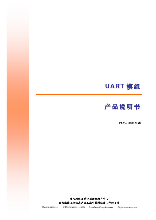
管脚
标号
功能
管脚 标号
功能
1
VCC
电源
4
Tx1 通道 1 发送
2
Tx2
通道二发送
5
Rx1 通道 1 接收
3
Rx2
通道二接收
6
GND 地
其中,Tx1 和 Rx1 配对构成一组异步串行收发通道,并使用 P1(九针母头串行接口)与 RS232 总 线通讯;Tx2 和 Rx2 配对构成另一组异步串行收发通道,并使用 P2(九针公头串行接口)与 RS232 总线通讯。
优 服 务
势 Advantage
z 61Job的目标企业用户仅定位于电子、通讯、计算机等IT行业企业 z 知名电子、通讯、IT行业企业云集, 招聘需求80%以上为技术、管理职位,找工作更具针对性 z 专业的网站注重专业细分,使目标职位范围的锁定更精准 z 61Job提供经过细分的电子行业人才求职工具,使专业人才求职更加便捷高效 z 国际IC设计公司合作背景,使我们具备资深专业工程师团队和管理层智囊团,为学生提供电子行业职业发展规划 指导 z 定期制作的电子人才月刊,将优秀人才直接推荐给企业,增加求职命中率 z 掌握及时准确的行业发展及企业招聘信息,定期为个人会员发送 z 与国内众多知名的电子行业媒体强强联手,扩大求职者被行业内企业关注的机会 z 组织业内企业联合开展校园招聘,为优秀学子提供更多就业资讯 z 为高校提供毕业生宣传平台,开展学生就业指导讲座 z 系统第一时间自动发送简历下载记录通知个人会员,附加企业公开信息,会员可自主了解企业背景,与企业取得 联系,掌握求职主动权。
61job电子人才网
简 网 站 介 About 61Job
61Job电子人才网()是国内最专业的电子类人才招聘网站。以电子微电子、计算机、通信、智能安 防、自动控制、汽车电子等领域的专业技术人才为核心资源。为全国数千家电子、IT类企业提供整体的招聘解决方案, 为优秀电子人才提供广阔的就业平台和渠道。
UART(通用异步收发传输器)
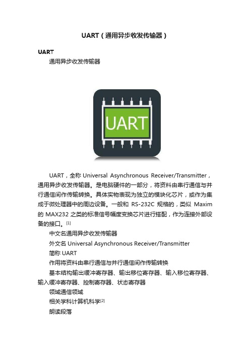
UART(通用异步收发传输器)UART通用异步收发传输器UART,全称Universal Asynchronous Receiver/Transmitter,通用异步收发传输器。
是电脑硬件的一部分,将资料由串行通信与并行通信间作传输转换。
具体实物表现为独立的模块化芯片,或作为集成于微处理器中的周边设备。
一般和RS-232C规格的,类似Maxim 的MAX232之类的标准信号幅度变换芯片进行搭配,作为连接外部设备的接口。
[1]中文名通用异步收发传输器外文名Universal Asynchronous Receiver/Transmitter简称UART作用将资料由串行通信与并行通信间作传输转换基本结构输出缓冲寄存器、输出移位寄存器、输入移位寄存器、输入缓冲寄存器、控制寄存器、状态寄存器领域通信领域相关学科计算机科学[2]朗读段落意见反馈硬件功能UART UART是一种通用串行数据总线,用于异步通信。
该总线双向通信,可以实现全双工传输和接收。
在嵌入式设计中,UART用来主机与辅助设备通信,如汽车音响与外接AP之间的通信,与PC机通信包括与监控调试器和其它器件,如EEPROM通信。
计算机内部采用并行数据,不能直接把数据发到Modem,必须经过UART整理才能进行异步传输,其过程为:CPU先把准备写入串行设备的数据放到UART的寄存器(临时内存块)中,再通过FIFO (First Input First Output,先入先出队列)传送到串行设备,若是没有FIFO,信息将变得杂乱无章,不可能传送到Modem。
它是用于控制计算机与串行设备的芯片。
有一点要注意的是,它提供了RS-232C数据终端设备接口,这样计算机就可以和调制解调器或其它使用RS-232C接口的串行设备通信了。
作为接口的一部分,UART还提供以下功能:将由计算机内部传送过来的并行数据转换为输出的串行数据流。
将计算机外部来的串行数据转换为字节,供计算机内部并行数据的器件使用。
UART应用开发套件硬件参考文档说明书

UART Application Kit Hardware ReferenceDigi document reference number: 90000922© Digi International Inc. 2008. All Rights Reserved.The Digi logo is a registered trademark of Digi International, Inc.All other trademarks mentioned in this document are the property of their respective owners. Information in this document is subject to change without notice and does not represent a commitment on the part of Digi International.Digi provides this document “as is,” without warranty of any kind, expressed or implied, including, but not limited to, the implied warranties of fitness or merchantability for a particular purpose. Digi may make improvements and/or changes in this manual or in the product(s) and/or the program(s) described in this manual at any time.This product could include technical inaccuracies or typographical errors. Changes are periodically made to the information herein; these changes may be incorporated in new editions of the publication.Digi International Inc.11001 Bren Road EastMinnetonka, MN 55343 (USA)* +1 877 912-3444 or +1 952 912-34442Contents1Overview (4)2Features (5)3Basic description (6)4Connection to development board (7)5Detailed description (8)5.1Block diagram (8)5.2UART (8)5.3Interrupt generation (10)5.4Chip Select decode (10)5.5Port configuration (11)5.6Transceivers (13)5.7Power save mode (13)6Memory map (15)7Connectors pinout (16)7.1Little-Endian Peripheral connector (16)7.2Big-Endian Peripheral connector (17)7.3Serial port A (18)7.4TTL port A (19)7.5Serial port B (19)7.6TTL port B (20)7.7Serial port C (20)7.8TTL port C (20)7.9Serial port D (21)7.10TTL port D (21)8Factory default configuration (22)3UART Application Kit - Hardware Reference1OverviewThis document describes the details of the UART application kit hardware board. This board will be called in advance UART_APPKIT.The UART_APPKIT provides four independent configurable RS232/422/485 serial ports. Eachserial port can be configured, by an on-board switch, for RS232 or RS422 or RS485 asynchronous communication in either full-duplex or half-duplex mode. A termination resistor can be added, by an on-board switch, to each port.The UART_APPKIT is designed to be connected to the peripheral connector of a JSCC9P9360,CCW9C_LC, JSCC9P9215, A9M2410DEV, or JSCC9M2443 board. The board will be powered from the base board.4UART Application Kit - Hardware Reference2FeaturesThe following are major features of the UART_APPKIT board:•Four (RS232/422/485) MEI serial configurable ports•Compatibility with the Industry Standard 16C750•64-byte transmit/receive FIFO with error flags•Up to 1.152Mbits/sec baud rate•Full modem RS232 ports•Configurable full-duplex or half-duplex RS485/422 ports•Configurable termination resistor for the RS485/422 ports•Four 9 way D type connector•One shared open collector interrupt for all the ports•Header connector pin to pin compatible with the JSCC9P and CCW9C_LC boards•Powered from the JSCC9P and CCW9C_LC boards.•±15kV ESD protection5UART Application Kit - Hardware Reference3Basic descriptionThe following figure shows the placement of the UART_APPKIT_0 board.6UART Application Kit - Hardware Reference4Connection to development boardThe UART_APPKIT_0 board has two connectors, X1 and X2 for connecting the kit to theJumpStart boards. Depending on the endianness of the CPU module the flat ribbon cable must be connected to a different connector in the UART_APPKIT.The following table shows the correspondence between the connectors of the UART_APPKIT and the supported modules.JumpStart Kit Module ConnectorJSCC9P9360 CC9P9360 X1CCW9C_LC CC9C / CCWi9C X1A9M2410DEV CC9M2440 X1JSCC9M2443 CC9M2443 X1JSCC9P9215 CC9P9215 X27UART Application Kit - Hardware Reference5Detailed description5.1Block diagramIRQ#, CS# ,ResetDecode5.2UARTThe UART_APPKIT board includes one quadruple UART to provide four serial ports. The UART used is the SC16C754 with 64-byte FIFOs, automatic hardware/software flow control, data rates up to 5Mbits/s.The UART transmits data, sent to it over the peripheral 8-bit bus, on the TX signal and receivescharacters on the RX signal. Characters can be programmed to be 5, 6, 7, or 8 bits. The UART hasa 64-byte receive FIFO and transmit FIFO and can be programmed to interrupt at different triggerlevels. The UART generates its own desired baud rate based upon a programmable divisor and its input clock. It can transmit even, odd, or no parity and 1, 1.5, or 2 stop bits. The receiver can detect break, idle, or framing errors, FIFO overflow, and parity errors. The transmitter can detect FIFOunderflow. The UART also contains a software interface for modem control operations, and hassoftware flow control and hardware flow control capabilities.8UART Application Kit - Hardware Reference95.2.1 Baud rate generatorThe SC16C754 UART contains a programmable baud generator that takes any clock input and divides it by a divisor in the range between 1 and (216 - 1). An additional divide-by-4 prescaler is also available and can be selected by the bit 7 of the MCR register. The output frequency of the baud rate generator is 16x the baud rate. The formula for the divisor is:()16x rate baud desired prescaler frequency input cystal XTAL1divisor ⎟⎟⎠⎞⎜⎜⎝⎛=Where:prescaler = 1, when MCR[7] is set to 0 after reset (divide-by-1 clock) (default) prescaler = 4, when MCR[7] is set to 1 after reset (divide-by-4 clock).One 18.432MHz crystal is used in the UART_APPKIT board to generate the baud rate. Thefollowing figure shows the baud rate and divisor correlation for crystal with frequency 18.432MHz.Desired baud rateDivisor used to generate 16xclockPercent errordifference between desired and actual110 10473 0.0026 300 3840 1200 960 2400 480 4800 240 9600 120 19200 60 38400 30 57600 20 115200 10 230400 5 576000 2 1152000 1The following figure shows the crystal clock circuit reference.UART Application Kit - Hardware Reference5.2.2UART resetThis Reset pin of the UART will reset the internal registers and all the outputs. The UARTtransmitter output and the receiver input will be disabled during reset time.RESET is an active-HIGH input.The UART registers DLL, DLH, SPR, Xon1, Xon2, Xoff1, Xoff2 are not reset by the Reset signal, and they hold their initialization values during reset.The peripheral connector does not have a reset signal from the main base board, so a memorymapped SW reset mechanism will be implemented on the UART_APPKIT. The address line A5will be used to generate the SW reset. To make a software reset of the UART a write operation has to be done to one address of the following address range:Chip Select (CS#) Write Enable (WE#) A5 – A0 Description0 0 1XXXXX UART SW Reset5.3Interrupt generationThe SC16C754 provides individual interrupt outputs for each port. Interrupt conditions include:receiver errors, available receiver buffer data, available transmit buffer space, or when a modemstatus flag is detected. The four interrupt outputs are high level active, and are in the high-impedance state after reset.The four interrupt outputs will be combined to generate a shared open collector interrupt output.This interrupt output will be an active low interrupt.5.4Chip Select decodeThe SC16C754 provides individual chip select inputs to enable data transfers between the CPU and each port of the UART. These chip select signal are low level active.In the peripheral connector of the UART_APPKIT board only one chip select signal is available.To select between the four different channels of the UART with only one chip select input a74LVC139 decoder is used. Address lines A4 and A3 are used to decode the four chip selects. The following table shows the memory map of the UART_APPKIT board.10Chip Select (CS#) A5 – A0 Description0 000000-000111 UART Channel A0 001000-001111UART Channel B0 010000-010111 UART Channel C0 011000-011111 UART Channel D5.5Port configurationThe UART_APPKIT board has four serial ports. Each serial port can be individually configuredwith a 4-switch. The switch has two positions: OPEN/OFF and CLOSED/ON:CLOSED/ONOPEN/OFFThe following paragraphs describe the configuration options.5.5.1RS232 / RS485If the pos-1 of the switch is closed, the serial port is configured to work in RS232 mode.If the pos-1 of the switch is open, the serial port is configured to work in RS485 mode.5.5.2Auto power downIf the pos-2 of the switch is closed the corresponding RS232 driver will be configured to work in AUTO ONLINE® mode. This mode will set the driver in low power consumption mode when the serial cable was disconnected or the serial peripheral was turned off.If the pos-2 of the switch is open the corresponding RS232 driver will be configured to work inalways online mode. In this mode the RS232 transceiver will not automatically enter in power save mode.5.5.3Full / half duplexIf the pos-3 of the switch is closed, the RS485 serial port is configured to work in half-duplexmode.If the pos-3 of the switch is open, the RS485 serial port is configured to work in full-duplex mode.5.5.4RS485 Termination resistorIf the pos-4 of the switch is closed, the serial port will have the termination resistor.If the pos-4 of the switch is open, the serial port will not have a termination resistor.5.5.5 Switch configurationsThe following table shows the switch configurations for each port of the UART_APPKIT.CLOSED/ONOPEN/OFFSwitch-1Switch-2Switch-3Switch-4DescriptionClosed Closed Closed Closed Not allowedClosed Closed Closed Open RS-232 with Auto Power down (default) Closed Closed Open Closed Not allowedClosed Closed Open Open RS-232 with Auto Power down Closed Open Closed Closed Not allowedClosed Open Closed Open RS-232 always enabled Closed Open Open Closed Not allowedClosed Open Open Open RS-232 always enabled Open Closed Closed Closed RS-485 , 2W, termination resistor Open Closed Closed Open RS-485 , 2W, No termination resistor Open Closed Open Closed RS-485 , 4W, termination resistor Open Closed Open Open RS-485 , 4W, No termination resistor Open Open Closed Closed RS-485 , 2W, termination resistor Open Open Closed Open RS-485 , 2W, No termination resistor Open Open Open Closed RS-485 , 4W, termination resistor Open OpenOpenOpenRS-485 , 4W, No termination resistor5.6 TransceiversEach serial channel of the UART_APPKIT board can be configured to work like RS232, RS485 or RS422 serial port.To generate the RS232 compliant signals one SP3243 device is used. The SP3243 is a RS232 compliant, 3-driver/5-receiver device. The SP3243 devices feature AUTO ON-LINE® circuitry which reduces the power supply drain to a 1μA supply current. In many portable or hand-held applications, an RS232 cable can be disconnected or a connected peripheral can be turned off. Under these conditions, the internal charge pump and the drivers will be shut down. Otherwise, the system automatically comes online. The following figure summarizes the logic of the AUTO ONLINE® operating modes.RS-232 Signal at Receiver InputSHUTDOWN#InputONLINE# OutputSTATUS# OutputTransceiver StatusYES HIGH LOW HIGHNormal Operation(Auto-Online)NO HIGH HIGH LOW Normal Operation NO HIGH LOW LOWShutdown (Auto-Online)YES LOW HIGH/LOW HIGH Shutdown NO LOW HIGH/LOW LOW ShutdownTo generate the RS485/RS422 serial signals one MAX3483 device is used. The MAX383 is ±15kVESD-protected, +3.3V, low-power full duplex transceivers for RS485 and RS422 communications. Each device contains one driver and one receiver that can transmit at up to 12Mbps.5.7 Power save modeThe UART_APPKIT board provides different configurable features to save power consumption. The following paragraphs describe the power save features.5.7.1 UART sleep modeThe SC16C754 UART has a sleep mode feature. Sleep mode is entered when: The serial data input line, RX, is idle The TX FIFO and TX shift register are empty.There are no interrupts pending except THR and time-out interrupts.In sleep mode, the UART clock and baud rate clock are stopped. Since most registers are clocked using these clocks, the power consumption is greatly reduced. The UART will wake up when any change is detected on the RX line, when there is any change in the state of the modem input pins, or if data is written to the TX FIFO.5.7.2Serial port enableEach serial channel of the UART_APPKIT board can be individually enabled or disabled. When a channel is disabled the transceivers are disabled and in low power consumption mode.To disable a serial port the configuration switch has to be configured in RS232, Auto power down, and the cable of the connector has to be disconnected.5.7.3RS232 transceiver AUTO ONLINE®If a serial port is enabled and in RS232 mode, it can be configured to work in AUTO ONLINE® mode. When configured in this mode the RS232 transceiver will automatically enter in power save mode if the RS232 cable is disconnected or if the connected peripheral is powered off.6Memory mapThe following table shows the memory map of the UART_APPKIT board.Chip Select (CS#) Write Enable (WE#) A5 – A0 Description0 x 000000-000111 UART Channel A0 x 001000-001111 UART Channel B0 x 010000-010111 UART Channel C0 x 011000-011111 UART Channel D0 0 1xxxxx UART SW Reset7Connectors pinout7.1Little-Endian Peripheral connectorPin Name Type Comment1 GND Ground2 D0 I/O3 D1 I/O4 D2 I/O5 D3 I/O6 GND Ground7 D4 I/O8 D5 I/O9 D6 I/O10 D7 I/O11 GND Ground12 - -13 - -14 - -15 - -16 GND Ground17 - -18 - -19 - -20 - -21 GND Ground22 - -23 GND Ground24 +3.3V Power25 +3.3V Power26 A0 I27 A1 I28 A2 I29 A3 I30 GND Ground31 A4 I32 A5 I33 - -34 - -Pin Name Type Comment35 GND Ground36 - -37 - -38 GND Ground39 CS# I40 - -41 IOWR# I42 IORD# I43 - -44 IRQ# OD45 +3.3V Power46 +3.3V Power47 - -48 - -49 - -50 GND Ground7.2Big-Endian Peripheral connectorPin Name Type Comment1 GND Ground2 -3 -4 -5 -6 GND Ground7 -8 -9 -10 -11 GND Ground12 D0 I/O13 D1 I/O14 D2 I/O15 D3 I/O16 GND Ground17 D4 I/O18 D5 I/OPin Name Type Comment19 D6 I/O20 D7 I/O21 GND Ground22 - -23 GND Ground24 +3.3V Power25 +3.3V Power26 A0 I27 A1 I28 A2 I29 A3 I30 GND Ground31 A4 I32 A5 I33 - -34 - -35 GND Ground36 - -37 - -38 GND Ground39 CS# I40 - -41 IOWR# I42 IORD# I43 - -44 IRQ# OD45 +3.3V Power46 +3.3V Power47 - -48 - -49 - -50 GND Ground7.3Serial port APin Name Type Comment1 DCDA_RS232#/CTSA-_RS4xx I2 RXA_RS232/RXA+_RS4xx IPin Name Type Comment3 TXA_RS232/TXA+_RS4xx O4 DRTA_RS232#/RTSA-_RS4xx O5 GND Ground6 DSRA_RS232#/RXA-_RS4xx I7 RTSA_RS232#/RTSA+_RS4xx O8 CTSA_RS232#/CTSA+_RS4xx I9 RIA_RS232#/TXA-_RS4xx I/O7.4TTL port APin Name Type Comment1 UART_DCDA# I2 UART_DSRA# I3 UART_RXA I4 UART_RTSA# O5 UART_TXA O6 UART_CTSA# I7 UART_DTRA# O8 UART_RIA# I/O9 GND G10 +3.3V P7.5Serial port BPin Name Type Comment1 DCDB_RS232#/CTSB-_RS4xx I2 RXB_RS232/RXB+_RS4xx I3 TXB_RS232/TXB+_RS4xx O4 DRTB_RS232#/RTSB-_RS4xx O5 GND Ground6 DSRB_RS232#/RXB-_RS4xx I7 RTSB_RS232#/RTSB+_RS4xx O8 CTSB_RS232#/CTSB+_RS4xx I9 RIB_RS232#/TXB-_RS4xx I/O7.6TTL port BPin Name Type Comment1 UART_DCDB# I2 UART_DSRB# I3 UART_RXB I4 UART_RTSB# O5 UART_TXB O6 UART_CTSB# I7 UART_DTRB# O8 UART_RIB# I/O9 GND G10 +3.3V P7.7Serial port CPin Name Type Comment1 DCDC_RS232#/CTSC-_RS4xx I2 RXC_RS232/RXC+_RS4xx I3 TXC_RS232/TXC+_RS4xx O4 DRTC_RS232#/RTSC-_RS4xx O5 GND Ground6 DSRC_RS232#/RXC-_RS4xx I7 RTSC_RS232#/RTSC+_RS4xx O8 CTSC_RS232#/CTSC+_RS4xx I9 RIC_RS232#/TXC-_RS4xx I/O7.8TTL port CPin Name Type Comment1 UART_DCDC# I2 UART_DSRC# I3 UART_RXC I4 UART_RTSC# O5 UART_TXC O6 UART_CTSC# I7 UART_DTRC# O8 UART_RIC# I/O9 GND GUART Application Kit - Hardware ReferencePin Name Type Comment10 +3.3V P7.9Serial port DPin Name Type Comment1 DCDD_RS232#/CTSD-_RS4xx I2 RXD_RS232/RXD+_RS4xx I3 TXD_RS232/TXD+_RS4xx O4 DRTD_RS232#/RTSD-_RS4xx O5 GND Ground6 DSRD_RS232#/RXD-_RS4xx I7 RTSD_RS232#/RTSD+_RS4xx O8 CTSD_RS232#/CTSD+_RS4xx I9 RID_RS232#/TXD-_RS4xx I/O7.10TTL port DPin Name Type Comment1 UART_DCDD# I2 UART_DSRD# I3 UART_RXD I4 UART_RTSD# O5 UART_TXD O6 UART_CTSD# I7 UART_DTRD# O8 UART_RID# I/O9 GND G10 +3.3V P21UART Application Kit - Hardware Reference228 Factory default configurationThe factory default configuration of the four MEIs is the following:Switch Status Description1 CLOSED/ON RS-232 mode2 OPEN/OFF Power save mode disabled3 OPEN/OFF 4W (for RS-485) 4OPEN/OFFNo termination resistor。
--异步UART通信-芯片资料课件 (一)

--异步UART通信-芯片资料课件 (一)异步UART通信是一种广泛应用于各种嵌入式系统中的串行通信协议。
在芯片资料课件中,常常会有针对UART通信的相关资料,这些资料对于学习和应用UART通信非常重要。
本文将介绍异步UART通信,并详细解析芯片资料课件中的相关内容。
一、异步UART通信异步UART通信是一种基本的串行通信方式。
在数据传输过程中,数据以位为单位依次传输,每个字节的传输分为起始位、数据位、校验位和停止位四个部分。
其中起始位固定为逻辑0,停止位则可以是逻辑0、逻辑1或两者的转换。
优点:1.简单实用:UART通信无需使用专用设备接口,只要通信的两个设备之间有相互连接的I/O引脚即可通信。
2.速度快:UART通信速度很快,能达到几十kbps以上的数据率。
缺点:1.不如同步通信协议可靠稳定。
2.传输距离相对有限,通常只能在几十米内实现。
二、芯片资料课件在芯片资料课件中,对于异步UART通信的介绍常常涉及到以下内容:1.数据格式:组成数据帧的基本单位是一个字节,包含起始位、数据位、校验位和停止位,其中起始位一般为逻辑0。
2.波特率:UART通信使用的是异步时序,因此对与发送和接收的数据的传输速率进行最基本的约束。
可以设置的波特率在软件配置时提供。
3.流控制:UART通信也可以使用流控制来协调数据传输。
例如,硬件流控制使用的是构成数据帧的传输引脚,而软件控制则是根据不同的端口协调数据传输。
4.缓冲区:UART通信需要使用接收缓冲区和发送缓冲区来协调数据传输,确保数据能够正确传输。
三、总结异步UART通信是一种基本的串行通信协议,在各种嵌入式系统中得到广泛应用。
在芯片资料课件中,通常会对其进行详细的介绍,包括数据格式、波特率、流控制和缓冲区等内容。
掌握这些内容不仅有助于对UART通信的理解,同时也有助于在软件开发中使用UART实现数据传输。
UART规格书
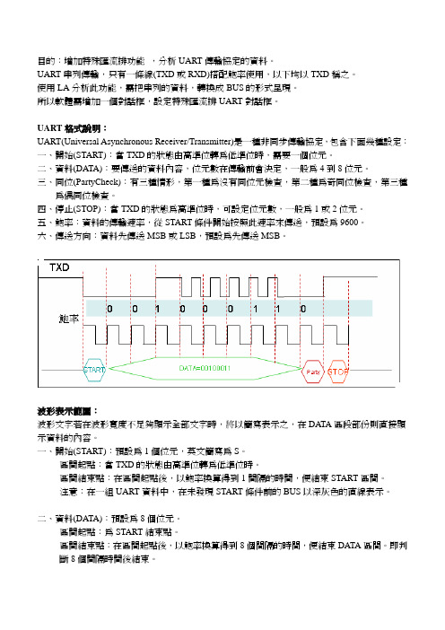
目的:增加特殊匯流排功能,分析UART傳輸協定的資料。
UART串列傳輸,只有一條線(TXD或RXD)搭配鮑率使用,以下均以TXD稱之。
使用LA分析此功能,需把串列的資料,轉換成BUS的形式呈現。
所以軟體需增加一個對話框,設定特殊匯流排UART對話框。
UART格式說明:UART(Universal Asynchronous Receiver/Transmitter)是一種非同步傳輸協定,包含下面幾種設定:一、開始(START):當TXD的狀態由高準位轉為低準位時,需要一個位元。
二、資料(DATA):要傳送的資料內容,位元數在傳輸前會決定,一般為4到8位元。
三、同位(PartyCheck):有三種情形,第一種為沒有同位元檢查,第二種為奇同位檢查,第三種為偶同位檢查。
四、停止(STOP):當TXD的狀態為高準位時,可設定位元數,一般為1或2位元。
五、鮑率:資料的傳輸速率,從START條件開始按照此速率來傳送,預設為9600。
六、傳送方向:資料先傳送MSB或LSB,預設為先傳送MSB。
波形表示範圍:波形文字若在波形寬度不足夠顯示全部文字時,將以簡寫表示之,在DATA區段部份則直接顯示資料的內容。
一、開始(START):預設為1個位元,英文簡寫為S。
區間起點:當TXD的狀態由高準位轉為低準位時。
區間結束點:在區間起點後,以鮑率換算得到1間隔的時間,便結束START區間。
注意:在一組UART資料中,在未發現START條件前的BUS以深灰色的直線表示。
二、資料(DATA):預設為8個位元。
區間起點:為START結束點。
區間結束點:在區間起點後,以鮑率換算得到8個間隔的時間,便結束DATA區間。
即判斷8個間隔時間後結束。
三、同位檢查(Party Chec k):預設沒有此位元,英文簡寫為C。
區間起點:為DATA的結束點。
區間結束點:在區間起點後,以鮑率換算得到1個間隔的時間,便結束PCK區間。
四、結束(STOP):預設為1個位元,英文簡寫為P。
uart总线协议标准文档
uart总线协议标准文档
Uart协议,也就是异步串行通信协议,是属于链路层的协议。
它规定了数据传送bit级的格式。
需要开始位,数据位,奇偶校验位,结束标志位。
具体要求可以搜索 uart协议的详细信息。
该协议之下包括了RS232-C,RS485等标准,也可以说是RS232和RS485协议,还可以称为RS232和RS485接口(这是因为UART本身也可翻译为通用异步串行收发器)。
无论RS232还是RS485,都属于物理层的协议标准,即二者都定义了各自的电平以及机械等接口标准。
另外,RS232只能实现单对单的通信,比如一个DB-9的数据线,只能连接两个终端。
而RS485则不同,他可以实现多台终端的联网,具体的接口可以采用DB-9也可以采用更加简单的双绞线连接。
总之,UART协议是不同终端之间通信的相互约定,他规定了数据的发送格式,即每一位二级制数据的具体意义;而RS232和RS485则规定了该协议在实现的时候的具体电平标准和机械标准。
对于RS232可以使用所有9根线,也可以只使用2,3,5,称为miniRS232,也可以同时在一个DB-9接口中同时接入两套输入输出信号,即两个RXD和两个TXD,当然此时要求另一个终端的接口也有相同的接线方式,当然也可以将一套禁用(配置芯片内寄存器),而只使用2,3,5,此时该接口退化为
miniRS232。
对于RS485而言,只使用2,3,5,或者只使用2,3,也可以简单的采用双绞线连接在两个终端之间。
笔记本中的uart协议
笔记本中的uart协议
UART(Universal Asynchronous Receiver/Transmitter,通用异
步收发器)是一种用于串行通信的协议。
在笔记本电脑中,UART协议被用于与外部设备进行串口通信。
UART协议通过传输数据的时序来实现通信。
它使用两根信号线,即接收线(RX)和发送线(TX),来进行数据的收发。
UART协议的基本原理是将要传输的数据按比特位划分,并通过发送线逐个比特地发送出去。
在接收端,接收线接收到数据,并将其按比特位重建成完整的数据。
UART协议的特点如下:
1. 异步性:发送端和接收端的时钟不需要相互同步。
发送端会通过起始位来标记数据的开始,接收端通过检测起始位来确定传输的开始。
2. 单工性:UART协议只能实现单向的数据传输,即发送端只能发送数据,接收端只能接收数据。
3. 数据格式:UART协议中的每个数据包包含一个起始位、数据位、校验位和停止位。
起始位用于标记数据的开始,停止位用于标记数据的结束,数据位用于传输实际的数据,校验位用于校验传输的正确性。
4. 波特率:UART协议通过设定波特率(单位为波特)来控制数据的传输速率。
波特率指定了每秒传输的比特数。
在笔记本电脑中,UART协议通常用于与其他外部设备进行串
口通信,例如与打印机、调制解调器、传感器等设备进行数据的传输和通信。
UART以及其他接口协议
UART以及其他接口协议UART,全称通用异步收发传输协议(Universal Asynchronous Receiver Transmitter),是一种同步和异步串行通信的标准协议。
它是应用于计算机串行端口通信的一种通信方式,由发送方和接收方之间通过一根数据线进行双向数据传输。
UART常用于连接计算机和外部设备,比如调制解调器、传感器、显示屏等。
UART的工作原理是通过固定的波特率(Baudrate)将数据分割为连续的帧发送。
每个帧由起始位、数据位、奇偶校验位和停止位组成。
发送方将数据输出到串行数据线上,接收方在接收数据同时进行同步,通过检测起始位的时刻来同步接收数据,然后按照固定的数据位顺序读取数据。
除了UART,还有一些其他常用的接口协议,包括I2C、SPI和CAN。
I2C,全称为Inter-Integrated Circuit,是一种短距离数据传输的串行通信协议,也被称为二线制串行总线。
I2C由两根线组成,一根为数据线(SDA),用于传输数据;另一根为时钟线(SCL),用于同步数据传输的时序。
I2C可以连接多个设备,通过设备地址进行通信。
SPI,全称为Serial Peripheral Interface,是一种同步的串行通信协议。
SPI通常由一个主设备和多个从设备组成,主设备负责控制通信的时序,并向从设备发送数据。
SPI使用了四根线,包括一个片选线(CS)用于选择从设备,一个时钟线(CLK)用于同步数据传输,一个主从数据线(MOSI)用于主设备向从设备发送数据,以及一个从主数据线(MISO)用于从设备向主设备发送数据。
CAN,全称为Controller Area Network,是一种用于实时应用的串行通信协议。
CAN常用于汽车电子系统、工业自动化等领域。
CAN总线由两根线组成,一根为CAN_H,用于传输高电平;另一根为CAN_L,用于传输低电平。
CAN使用触发型通信方式,在总线上允许多个设备同时发送数据。
uart边沿时间和高低电平
uart边沿时间和高低电平
(原创版)
目录
1.UART 简介
2.UART 边沿时间
3.UART 高低电平
4.UART 在电子通信中的应用
正文
1.UART 简介
UART,全称为 Universal Asynchronous Receiver/Transmitter,即通用异步收发器,是一种串行通信接口,广泛应用于电子设备之间的数据传输。
UART通过将数据字符从并行转换为串行,以及将从串行转换为并行的数据字符,实现设备间的通信。
2.UART 边沿时间
UART 边沿时间是指数据传输过程中,数据位从高电平到低电平或从低电平到高电平所需的时间。
UART 边沿时间分为上升沿时间和下降沿时间。
在 UART 通信中,数据的发送和接收都是以边沿时间为基准的。
3.UART 高低电平
UART 通信中,数据以高低电平的形式进行传输。
高电平通常表示数据为 1,低电平通常表示数据为 0。
UART 的高低电平阈值可以根据实际通信需求进行调整。
通常情况下,UART 的高低电平阈值为正负 200mV 至正负 600mV。
4.UART 在电子通信中的应用
UART 作为通用的串行通信接口,广泛应用于各种电子设备之间的通
信。
例如,计算机与外设、单片机与传感器、通信设备与终端设备等之间的数据传输。
通过 UART 接口,可以实现设备间的数据传输和通信控制,满足各种应用场景的需求。
