VEML6035环境光传感器威世通用
NetBotz
将传感器连接到 Sensor 端口.................................... 9 连接警报信号灯和其他可选设备................................. 10 将传感器和传感器盒连接到 A-Link 端口 ......................... 11
NetBotz 快速配置 ............................................ 18
配置装置设置 . . . . . . . . . . . . . . . . . . . . . . . . . . . . . . . . . . . . . . . . . . . . 18 配置警报操作 . . . . . . . . . . . . . . . . . . . . . . . . . . . . . . . . . . . . . . . . . . . . 19
传感器规格................................................... 29
担保 ................................................................................. 30
两年期出厂担保............................................... 30
NetBotz 配置向导 ............................................ 15
NetBotz 机架监视器 450/550/570 安装和快速配置手册
i
访问装置..................................................... 15
VESDA-E VEU VEP 产品指南说明书
上海市浦东新区张江高科技园区环科路555号邮编:201202 VESDA-E VEU/VEP产品指南S00-2080-000-01/19/2021概述VESDA-E VEU-Axx-NTF和VEP-Axx-NTF是基于VESDA-E VEU-Axx探测器打造的高端产品,内置SLC接口,可通过SLC回路与智能火灾控制器通信。
本指南包括支持SLC环路的VEU-Axx-NTF-CH和VEP-Axx-NTF-CH的安装、调试和配置信息,SLC的布线和规格参数,以及与基本探测器型号(VESDA-E VEU-Axx和VEP-Axx)间的差异信息。
使用本指南时,请配合参阅相应基本探测器的产品指南,具体请见下文“相关产品文档”部分.本指南假定使用本产品的所有人员都具备相关知识和本地消防和电气部门的资格认证。
注: 对VEU Axx-NTF-CH和VEP-Axx-NTF-CH或VEU-Axx-CH和VEP-Axx-CH的参考信息,适用于VESDA-E VEU和VEP的所有已上市型号,具体型号请参阅下文“订购信息”部分.空气采样烟雾探测的规范和标准我们强烈建议阅读本文档时,一并参阅适用的本地烟雾探测和电气连接规范及标准。
本文档包含通用产品信息,其中部分信息可能不符合所有本地规范及标准。
在此情况下,以本地规范和标准为准。
以下信息在付印时确认无误,但可能会过时,请查阅您本地的规范、标准和目录以了解当前限制。
FCC合规声明本设备经测试证明符合FCC(美国联邦通信委员会)规则第15部分B类数字设备的限制。
这些限制旨在提供合理的保护,以防止对住宅设施产生有害干扰。
此设备会生成、使用并发射射频能量,如果未按照说明安装和使用,可能会对无线电通信造成有害干扰。
因此,不能保证在具体安装中不会发生干扰。
如果此设备确实对无线电或电视接收造成有害干扰,那么建议用户尝试通过以下一种或多种措施来消除干扰:调整接收天线的方向或位置;增加设备与接收装置之间的间隔;将设备连接到与接收装置位于不同电源电路的其他插座中;咨询经销商或专业无线电/电视技术人员以获得帮助。
夏普光耦选型手册
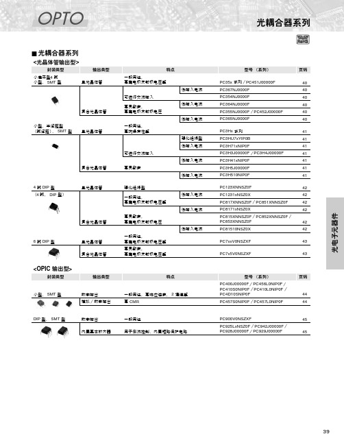
PC357NJ0000F
一般用途 一般用途, 高抗噪声性*1 高集电极发射极 电压 低输入电流, 高抗噪声性*1 可进行交流输入 低输入电流, 可进行交流输入, 高抗噪声性*1 高灵敏度
⅜❇
PC352NJ0000F 单 光 晶 体 管 输 出
⅜
50
3.75
80
90
5
5
4
2
100
2
PC451J00000F
PC714V0NSZXF PC724V0NSZXF
高绝缘电压 高绝缘电压, 大输入电流 高绝缘电压, 带基底端子 高绝缘电压, 高灵敏度 高绝缘电压, 高灵敏度, 高集电极发射极电压, 大功率
小型, SMT 型
数字输出 模拟/数字输出
一般用途,高响应速度, 2 通道等 高 CMR
44 44
DIP 型, SMT 型
数字输出 内置基本放大器
一般用途 用于倒流控制,内置短路保护电路
PC900V0NSZXF PC925LxNSZ0F /PC942J00000F/ PC928J00000F/PC929J00000F
安全标准*8
绝对最大额定值
光电特性
PC123XNNSZ0F*1, *5, *6, *7 单 PC1231xNSZ0X*1 光 晶 体 PC817XNNSZ0F*5, *6, *7 管 输 PC8171xNSZ0X*5, *6 出 PC851XNNSZ0F*5, *6
高绝缘电压,强化绝缘型 高绝缘电压,强化绝缘型, 低输入电流,高抗噪声性*4 高绝缘电压 高绝缘电压,低输入电流, 高抗噪声性*4 高绝缘电压, 高集电极发射极电压 高绝缘电压,高灵敏度 高绝缘电压, 高灵敏度,低输入电流 高绝缘电压, 高集电极发射极电压 高绝缘电压, 高集电极发射极电压
光电传感器SOOD、SOOE产品特性和范围概述说明书

光电传感器Subject to change –2018/102→Internet:/catalogue/...光电传感器SOOD,SOOE主要特性和产品范围一览产品范围一览派生型SOOD LEDSOOD 激光SOOE LED SOOE 激光→页码/Internet 漫反射式传感器,带背景抑制⏹⏹⏹⏹12,24对射式传感器⏹⏹⏹⏹18,28反射式传感器⏹⏹⏹⏹21,32反射式传感器,用于透明物体––⏹–35漫反射式传感器––⏹–38激光,对比传感器–––⏹42激光,距离传感器––⏹⏹46检测方法漫反射式传感器SOOE-DS这些传感器有时候被称为能量传感器,发射器和接收器同处一个壳体内。
发射出的光束直接被物体反射到接收器,计算反射光束的强度。
通过改变接收器(用IO-Link®、电位计或示教方法)的灵敏度可调节工作距离。
漫反射式传感器是成本效益最高的解决方案之一,安装也十分快捷。
不过,这些传感器不适用于一些应用场合,例如在强反射背景下检测轻微反光的物体。
此外,采用多种不同表面的物体(从材料、颜色或表面光洁度的角度出发)因为不同表面的反射特性不同,所以需要在不同的距离进行测量。
漫反射式传感器的优点在于强度区分。
•工作距离更长•经济性更佳•检测轻微反光的物体时更可靠-V-新产品光电传感器SOOD,SOOE 主要特性漫反射式传感器,带背景抑制工作距离并非通过能量来设定,而是通过光学三角测量。
全新且高精度的多像素技术(SOOE)有着优异的灵活性,通过IO-Link®设置。
带160x16像素的信号预处理的集成接收器是精确检测与距离测量的关键。
该接收器具备高分辨率和线性化,在检测范围上限有着独特的设定性能。
因此,物体检测几乎独立于背景中的其它物体之外,也与颜色、大小或表面光洁度无关。
这些设备仅要求有非常少量的漫反射。
带背景抑制的漫反射式传感器的优点•工作距离实际上与颜色和表面光洁度无关•还可用于闪光或反光的背景•检测距离的小差异•调节方便反射式传感器这些传感器的发射器和接收器也同处一个壳体内。
迪士大斯可见度传感器PWD50说明书
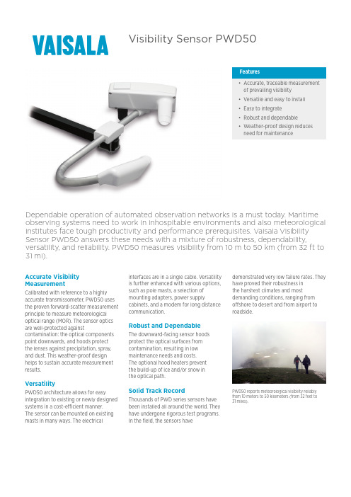
Visibility Sensor PWD50Features•Accurate, traceable measurementof prevailing visibility•Versatile and easy to install•Easy to integrate•Robust and dependable•Weather-proof design reducesneed for maintenanceDependable operation of automated observation networks is a must today. Maritime observing systems need to work in inhospitable environments and also meteorological institutes face tough productivity and performance prerequisites. Vaisala Visibility Sensor PWD50 answers these needs with a mixture of robustness, dependability, versatility, and reliability. PWD50 measures visibility from 10 m to 50 km (from 32 ft to 31 mi).Accurate Visibility MeasurementCalibrated with reference to a highly accurate transmissometer, PWD50 uses the proven forward-scatter measurement principle to measure meteorological optical range (MOR). The sensor optics are well-protected against contamination: the optical components point downwards, and hoods protect the lenses against precipitation, spray, and dust. This weather-proof design helps to sustain accurate measurement results.VersatilityPWD50 architecture allows for easy integration to existing or newly designed systems in a cost-efficient manner.The sensor can be mounted on existing masts in many ways. The electrical interfaces are in a single cable. Versatilityis further enhanced with various options,such as pole masts, a selection ofmounting adapters, power supplycabinets, and a modem for long distancecommunication.Robust and DependableThe downward-facing sensor hoodsprotect the optical surfaces fromcontamination, resulting in lowmaintenance needs and costs.The optional hood heaters preventthe build-up of ice and/or snow inthe optical path.Solid Track RecordThousands of PWD series sensors havebeen installed all around the world. Theyhave undergone rigorous test programs.In the field, the sensors havedemonstrated very low failure rates. Theyhave proved their robustness inthe harshest climates and mostdemanding conditions, ranging fromoffshore to desert and from airport toroadside.PWD50 reports meteorological visibility reliablyfrom 10 meters to 50 kilometers (from 32 feet to31 miles).T echnical DataMeasurement PerformanceOperating principle Forward scatter measurement with45° scattering angleObservation range of MOR10 … 50 000 m (32 … 164 000 ft) Accuracy±10 % at 10 … 10 000 m(32 … 32 800 ft)±20 % at 10 … 50 km (6.2 … 31 mi)Operating EnvironmentOperating temperature−40 … +60 °C (−40 … +140 °F) Operating humidity0 ... 100 %RHInputs and OutputsPower supply12 … 50 VDC (electronics)24 VAC or 24 VDC for heater option Average power consumption 3 W (peak 10 W)With optional luminance sensor: 5 WWith optional hood heaters: 65 W Outputs Serial data line may be used either asRS‑232 or RS‑485 (2‑wire) levelsignals3 relay controls (open collector)Analog output current: 0 ... 1 mA or4 ... 20 mA8-m power/data cable standard.The PWD end is equipped withconnector.Auxiliary data Low visibility alarms in the datamessages. 3 adjustable alarm limits toset the 3 relay controls.Hardware status (fail/warning) inthe data messages. Third relay controloutput can also be driven byhardware status.Mechanical SpecificationsIP rating IP66Weight 3 kg (6.61 lb)Dimensions (H × W × L)140 × 404 × 695 mm(5.51 × 15.91 × 27.36 in)ComplianceEMC ComplianceRadiated emissions CISPR 16-1CISPR 16-2Radiated susceptibility IEC 61000-4-3, 10 V/mConducted emissions CISPR 16-1CISPR 16-2Conducted susceptibility IEC 61000-4-6EFT immunity IEC 61000-4-4ESD immunity IEC 61000-4-2Surge IEC 61000-4-5Spare Parts and AccessoriesPole mastInterface unit with power supplies: 115/230 VACLuminance sensor PWL111Hood heaters for harsh winter conditionsSupport arm for mast installationsPole clamp kit for mast top installationsCalibration set PWA12Maintenance cable 16385ZZMaritime insulatorIn addition to meteorological observation networks, PWD50 is also well-suited for use in offshore operations.Published by Vaisala | B211069EN-C © Vaisala 2018All rights reserved. Any logos and/or product names are trademarks of Vaisala or its individual partners. Any reproduction, transfer, distribution or storage of information contained in this document is strictly prohibited. All specifications — technical included — are subject to change without notice.。
维萨拉红外二氧化碳传感器应用注释说明书

www.vaisala.cn应用注释红外传感器的操作原理二氧化碳和由两个或更多不同原子组成的其他气体以独特的方式吸收红外线 (IR) 辐射。
可使用 IR 技术检测这类气体。
例如,可使用 IR 传感器测量水蒸汽、甲烷、二氧化碳和一氧化碳的含量。
其特征吸收谱带显示在图 1 中。
IR 传感是应用广泛的一种 CO 2 检测技术。
IR 传感器与化学传感器相比有很多优势。
它们稳定,且对于测量的气体具有高选择性。
它们的使用寿命长,因为测量的气体不直接与传感器作用,IR 传感器可以承受高湿度、灰尘、脏污和其他恶劣环境。
很多应用领域(从建筑自动化和温室到生命科学和人身安全)都需要进行二氧化碳测量。
本文档涉及以下主题:•红外二氧化碳 (CO 2) 传感器的操作原理•理想气体定律以及如何使用它来针对环境因素补偿 CO 2 测量值•CO 2 变送器的最佳位置•与 CO 2 有关的安全问题如何测量二氧化碳图 1. CO 2 和一些其他气体的 IR 吸收量IR CO 2 检测器的核心部件是光源、测量室、干扰滤波器和 IR 检测器。
IR 辐射从光源通过测量的气体导向到检测器。
位于检测器前面的滤波器防止非测量气体特有的波长抵达检测器。
检测光强度并将其转换为气体浓度值。
维萨拉 CARBOCAP ® 二氧化碳传感器使用 IR 红外传感技术来测量 CO 2 的体积浓度。
它采用独特的电可调法布里-珀罗干涉仪 (FPI) 滤波器进行双波长测量。
这意味着除了测量 CO 2 吸收量外,CARBOCAP ® 传感器还执行参考测量,该测量可补偿光源强度的变化以及光路中的污染和污垢积聚。
这使传感器随着时间的推移也非常稳定。
有关用于 CO 2 测量的所有维萨拉产品系列,请访问:/CO 2波长 (nm)传输 (%)IR sensor detectsTemperature increasesfewer CO2molecules.at constant pressure.IR sensor detectsmore CO2molecules.Pressure increases atconstant temperature.pV = nRT其中p = 压力 [Pa]V = 气体体积 [m3]n = 气体量 [mol]R = 通用气体常数(= 8.3145 J/mol K)T = 温度 [K]图 2.维萨拉 CARBOCAP® CO2传感器的结构恒温时压力增加恒压时温度增加CO2变送器的最佳位置•避免放在人呼吸的气体可能会直接传到传感器的位置。
罗克威尔自动化871TM系列电磁感应接近传感器说明书
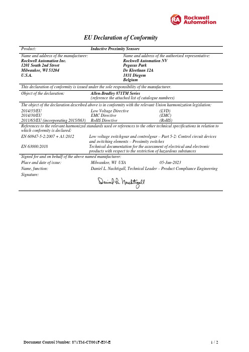
EU Declaration of Conformity Product: Inductive Proximity SensorsName and address of the manufacturer: Rockwell Automation Inc.1201 South 2nd StreetMilwaukee, WI 53204U.S.A. Name and address of the authorised representative: Rockwell Automation NVPegasus ParkDe Kleetlaan 12A1831 DiegemBelgiumThis declaration of conformity is issued under the sole responsibility of the manufacturer.Object of the declaration: Allen-Bradley 871TM Series(reference the attached list of catalogue numbers)The object of the declaration described above is in conformity with the relevant Union harmonization legislation: 2014/35/EU Low Voltage Directive (LVD)2014/30/EU EMC Directive (EMC)2011/65/EU (incorporating 2015/863) RoHS Directive (RoHS)References to the relevant harmonized standards used or references to the other technical specifications in relation to which conformity is declared:EN 60947-5-2:2007 + A1:2012 Low voltage switchgear and controlgear – Part 5-2: Control circuit devicesand switching elements – Proximity switchesEN 63000:2018 Technical documentation for the assessment of electrical and electronicproducts with respect to the restriction of hazardous substancesSigned for and on behalf of the above named manufacturer:Place and date of issue:Milwaukee, WI USA 05-Jun-2023Name, function:Daniel L. Nachtigall, Technical Leader – Product Compliance Engineering Signature:number is given, then all series are certified.2) Yes = Product is certified to this directive.N/R = This directive is not required for this product.NOMENCLATURE:。
哈希公司水质监测仪器说明书

哈希公司成立于1947年,现为美国丹纳赫集团一级子公司,总部设在美国科罗拉多州的拉夫兰市,是设计和制造水质、水文监测仪器的专业厂家。
工厂分别分布于美国、瑞士、德国、法国和英国。
作为水质、水文监测仪器的世界领导者,哈希公司产品被全球用户广泛应用于饮用水、地下水、地表水、市政污水、工业污水、半导体超纯水、制药/电力及其他工业净水、等领域,其全线产品系列涵盖实验室定性/定量分析、现场分析、流动分析测试、在线分析测试。
产品具有测量精确、运行可靠、操作简单、低维护量,结构紧凑等特点。
哈希公司一直致力于使水质分析过程更方便、更迅捷、更可靠:各类包装的即开即用型化学试剂包,不仅为精确的化学分析提供了可靠的质量保障,也为用户节约了宝贵的时间和人力资源,成为了中国环境现场应急监测的首选工具;各种类型的在线水质分析仪器,以其准确度高、维护量小、可测量的水质参数多等特点,可以满足污水处理厂、饮用水厂、工业过程水处理、工业污染源、水质自动监测站等不同场合的应用。
哈希公司的水质分析仪器产品在中国已经有超过20年的成功应用, 哈希在线水质分析仪器在中国水处理市场以及全球范围内都得到了广泛的应用,一直以来哈希在线浊度分析仪都是饮用水行业关键性运行指标-浊度测试的常用仪器。
我们的目标是继续为广大用户提供可靠的仪器、测试方法、简单的操作步骤和优质的客户服务,不断地提高产品的质量以满足客户需求不断变化的需要。
目前公司已经在北京、上海、广州和重庆、沈阳、西安、武汉、济南、南京、福州设立了办事处,为中国的广大客户提供方便、周到的服务。
目录水位监测 (2)流量监测 (12)雨量监测 (29)气象监测 (31)水质监测 (33)典型应用 (60)基本介绍用于连续测量水位的精巧型气泡水位计。
它具有高量程、高精度的特点,并带有4-20 mA 模拟输出和SDI12标准接口,最新设计的智能型气泵可以在满足测量精度的前提下减小打气体积,以便节省系统功耗。
第七批北京市新技术新产品(服务)名单

第七批北京市新技术新产品(服务)名单
序号
1
ห้องสมุดไป่ตู้
单位名称
产品(服务)名称
型号/规格
DLS1000/600、 DLS1200/600、 DLS2000/600、 DLS3000/600
技术领域
新一代信息技术
应用领域
其他
北京凯普林光电科技股份 千瓦级直接应用半导体激 有限公司 光器子系统
2
Q100-D、Q200-D、 Q400-D、Q100-E、 同辉佳视(北京)信息技 Q-Share智能交互会议终端 Q200-E、Q400-E、 新一代信息技术 术股份有限公司 C100-A、C200-A、 C400-A 清投智能(北京)科技股 份有限公司 智能佳(北京)机器人有 限公司 北京沃富瑞德文化传播有 限公司 北京文安智能技术股份有 限公司 北京赛普乐科技有限责任 公司 神州网云(北京)信息技 术有限公司 北京华电云通电力技术有 限公司 北京沃富瑞德文化传播有 限公司 北京首冠教育科技股份有 限公司 北京智汇空间科技有限公 司 艾坦姆流体控制技术(北 京)有限公司 北京沃富瑞德文化传播有 限公司 北京沃富瑞德文化传播有 限公司 北京华电云通电力技术有 限公司 电力巡检机器人 超声波机器人 VOFRID大屏幕可视化互动 展示系统 公交客流统计智能一体机 数字集群调度系统 网镜高级威胁检测系统 电容型设备在线监测装臵 VOFRID大屏幕可视化互动 管理系统 首冠在线教育平台 北斗智能车载终端 一种新型智能电气阀定位 器 一种表面显示的浮雕照片 或图画显示屏 一种可视面可变幻出各种 场景的AR鱼缸 金属氧化物避雷器绝缘在 线监测系统 TR33W011 TR33W011-1.0 super系列 V1.0 VT-COUNT-SFB PDDS V1.0 MC2100 V1.0 V1.0 SV321 SV322 SV323 U529系列 VOFD-46 VOYG-A MC2200 新一代信息技术 新一代信息技术 新一代信息技术 新一代信息技术 新一代信息技术 新一代信息技术 新一代信息技术 新一代信息技术 新一代信息技术 新一代信息技术 新一代信息技术 新一代信息技术 新一代信息技术 新一代信息技术
VEML6035-SB 传感器板指南说明书
VEML6035-SBSensor Board Guide Vishay SemiconductorsSensor Board Guide for VEML6035-SB INTRODUCTIONThe sensor board gives you the opportunity to evaluate the digital sensor. With a sensor board you can evaluate the sensor without thinking about a hardware solution for your development kit. If you also want to start directly with the evaluation of the sensor, you can easily purchase the complete system solution from Vishay including the SensorXplorer and a software module for the sensor. Then you can immediately start to evaluate the properties of the sensor itself.SensorXplorer™The SensorXplorer is a demonstration kit designed to help evaluate Vishay’s digital sensors featured on Vishay’s sensor boards. These boards, along with their respective software modules, can be used to demonstrate and test each sensor’s functionalities, allowing the user to quickly understand how various settings affect the sensor’s results. The SensorXplorer board includes an USB to I2C interface chip, a 3.3 V regulator, several indicator LEDs, as well as multiple GPIOs to control the functionality of each board and allow data to be read and displayed on a PC. To get an overview of available sensor boards, as well as to download the software modules and board design files, please visit: /optoelectronics/SensorXplorer. Here you will also find a link next to each board showing its availability at each of our distributors.For more information about the SensorXplorer find the installation guide by following this link: /doc?84922 Find all information where you can purchase a SensorXplorer or a specific sensor board by following this link:/optoelectronics/SensorXplorerThe SensorXplorer is a demonstration kit designed to help evaluate Vishay’s digital sensors featured on Vishay’s sensor boards. These boards, along with their respective software modules, can be used to demonstrate and test each sensor’s functionalities, allowing the user to quickly understand how various settings affect the sensor’s results. The SensorXplorer board includes an USB to I2C interface chip, a 3.3 V regulator, several indicator LEDs, as well as multiple GPIOs to control the functionality of each board and allow data to be read and displayed on a PC. To get an overview of available sensor boards, as well as to download the software modules and board design files, please visit: /optoelectronics/SensorXplorer. Here you will also find a link next to each board showing its availability at each of our distributors.USING THE SENSOR BOARD WITH THE SensorXplorerWhen using the complete Vishay solution with the SensorXplorer and sensor board you just need to install the software of the SensorXplorer when using first time on your PC. After that you need to connect the SensorXplorer with your PC and the sensor board with the SensorXplorer. Then start the demosoftware which you can find on our website by following this link: /landingpage/SensorXplorer/Now you can explore the sensor with its different settings and how they fit at its best for your application.Sensor Board Guide Vishay SemiconductorsHOW TO USE THE DEMOSOFTWAREWhen using the complete Vishay solution with the SensorXplorer and sensor board you just need to install the software of the SensorXplorer when using first time on your PC. After that you need to connect the SensorXplorer with your PC and the sensor board with the SensorXplorer. Then start the demosoftware which you can find on our website by following this link: /landingpage/SensorXplorer/Now you can explore the sensor with its different settings and how they fit at its best for your application.Controlmeaclear the graphSensor Board Guide Vishay SemiconductorsUSING THE SENSOR BOARD FOR ITSELFIf you want to use the sensor board within your own application and with own self-written software for communication with the sensor you just need to connect the board to power (3.3 V, GND) and the I2C-lines (SDA, SCL) as you can see in the figure below.Sensor Board Guide Vishay SemiconductorsSCHEMATIC OF THE VEML6035 SENSOR BOARDSensor Board Guide Vishay SemiconductorsASSEMBLY OF THE VEML6035 SENSOR BOARDBILL OF MATERIALSITEM QUANTITY REFERENCE COMPONENT CLASS VALUE PACKAGE11C1Capacitor NP100 nF SMC060321D1LED red VLMS1300SMD060331R1Resistor300 ΩSMR060341R2Resistor 4.7 kΩSMR060351U1Sensor VEML6035SMD61J1Edge connector 2 x 8 pos.SMD header stripVEML6035-SB。
海利尔C7130A,B墙面挂载空气温度传感器说明书
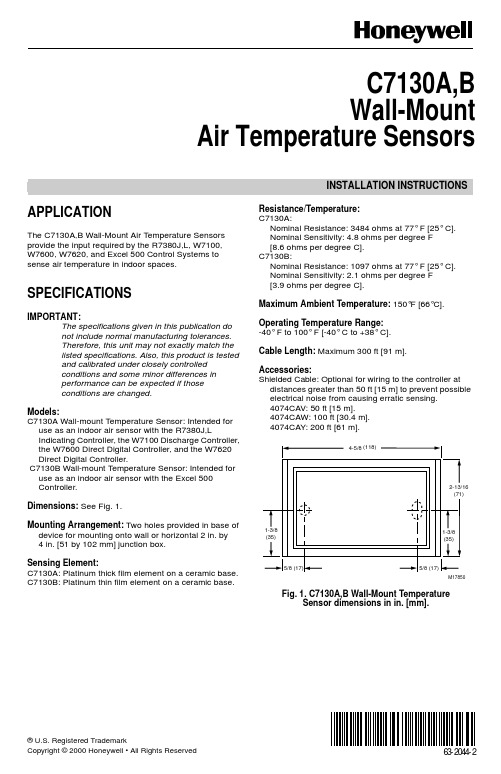
® U.S. Registered TrademarkCopyright © 2000 Honeywell • All Rights Reserved INSTALLATION INSTRUCTIONS63-2044-2C7130A,B Wall-MountAir Temperature SensorsAPPLICATIONThe C7130A,B Wall-Mount Air Temperature Sensors provide the input required by the R7380J,L, W7100,W7600, W7620, and Excel 500 Control Systems to sense air temperature in indoor spaces. SPECIFICATIONSIMPORTANT:The specifications given in this publication donot include normal manufacturing tolerances.Therefore, this unit may not exactly match thelisted specifications. Also, this product is testedand calibrated under closely controlledconditions and some minor differences inperformance can be expected if thoseconditions are changed.Models:C7130A Wall-mount Temperature Sensor: Intended for use as an indoor air sensor with the R7380J,LIndicating Controller, the W7100 Discharge Controller, the W7600 Direct Digital Controller, and the W7620 Direct Digital Controller.C7130B Wall-mount Temperature Sensor: Intended for use as an indoor air sensor with the Excel 500Controller.Dimensions: See Fig. 1.Mounting Arrangement: Two holes provided in base of device for mounting onto wall or horizontal 2 in. by4in. [51 by 102 mm] junction box.Sensing Element:C7130A: Platinum thick film element on a ceramic base. C7130B: Platinum thin film element on a ceramic base.Resistance/Temperature:C7130A:Nominal Resistance: 3484 ohms at 77° F [25° C].Nominal Sensitivity: 4.8 ohms per degree F[8.6 ohms per degree C].C7130B:Nominal Resistance: 1097 ohms at 77° F [25° C].Nominal Sensitivity: 2.1 ohms per degree F[3.9 ohms per degree C].Maximum Ambient Temperature: 150°F [66°C]. Operating Temperature Range:-40° F to 100° F [-40° C to +38° C].Cable Length: Maximum 300 ft [91 m].Accessories:Shielded Cable: Optional for wiring to the controller at distances greater than 50 ft [15 m] to prevent possible electrical noise from causing erratic sensing.4074CAV: 50 ft [15 m].4074CAW: 100 ft [30.4 m].4074CAY: 200 ft [61 m].Fig. 1. C7130A,B Wall-Mount TemperatureSensor dimensions in in. [mm].M178502-13/16(71)1-3/8(35)5/8 (17)5/8 (17)4-5/8(118)1-3/8(35)C7130A,B WALL-MOUNT AIR TEMPERATURE SENSORS63-2044—22INSTALLATIONWhen Installing this Product...1.Read these instructions carefully. Failure to follow them could damage the product or cause a hazardous condition.2.Check the ratings given in the instructions and on the product to make sure the product is suitable for your application.3.Installer must be a trained, experienced service technician.4.After installation is complete, check out product operation as provided in these instructions.IMPORTANTAll wiring must agree with applicable codes, ordinances and regulations.CAUTIONElectrical Shock or Equipment Damage Hazard.Can shock individuals or short equipment circuitry.Disconnect power supply before installation.Mounting And LocationMount the C7130 Wall-mount Temperature Sensor where the thermostat setting will not be subjected to tampering:1.Choose a location for the sensor on an insidewall about 5 ft [1.5 m] above the floor. A horizontally mounted standard 2 in. by 4 in. [51 mm by 102 mm] junction box may also be used at the selected location for the C7130.2.Place the sensor 300 ft [91 m] or less from thecontroller.3.Make sure that there is good air circulation ataverage temperature at the chosen location. Avoid the following locations because they can introduce errors in sensor measurements (see Fig. 2):—Hot areas caused by:Concealed pipes or ducts.Drafts from fireplaces or other heat sources.Convection or radiant heat from the sun or electrical equipment.—Cold areas caused by:Concealed pipes or ducts.Drafts from windows and doors.Unheated areas on the other side of the wall location.—Dead air areas:Behind doors, furniture, and curtains.In corners and alcoves.4.Mark the area on the wall where the C7130 Sensoror junction box will be mounted.Fig. 2. C7130 mounting location.WiringCAUTIONErratic System Operation Hazard.Failure to follow proper wiring practices can introduce disruptive electrical interference (noise).Keep wiring at least one foot away from large inductive loads such as motors line starters, lighting ballasts, and large power distribution panels.Shielded cable is required in installations where these guidelines cannot be met.Ground shield only to grounded controller case.IMPORTANT1.All wiring must agree with applicable codes, ordinances and regulations.2.Do not mount sensor in incorrect environment.3.Wire according to the applicable controller instructions.4.Avoid poor wiring connections.5.Avoid intermittent or missing building earth ground.Disconnect the power supply before connecting thewiring to prevent electrical shock or equipment damage. Wiring must comply with applicable codes, ordinances and regulations.Wire the C7130 Sensor to the temperature controller using the procedure in the controller instructions. For an example of general wiring of the C7130, see Fig. 3.Mount the C7130 to the wall or to the junction box.M9175C7130A,B WALL-MOUNT AIR TEMPERATURE SENSORS363-2044—2Fig. 3. General wiring hookup for C7130A sensor to R7380 Controller.CABLE SHIELD( 2-WIRE SHIELDED RECOMMENDED FOR RUNS OVER 50 FT . (15M)R7380CONTROLLER SENSOR24V POWER GROUNDGREENBLACK BLACKEARTH GROUNDDO NOT CONNECT SHIELD AT C7130A24 VAC2211BACKSIDE OF C7130A SENSOR24 VAC SUPPLY. DO NOT GROUND ANY 24 VAC LEADS.GROUND SHIELD OF SENSOR WIRING AT EARTH GROUND AT THE CONTROL ONLY. DO NOT GROUND AT SENSOR.M1098463-2044—2 B.B. Rev. 12-00 Printed in U.S.A. on recycled paper containing at least 10% post-consumer paper fibers.Home and Building Control Home and Building ControlHoneywellHoneywell Limited-Honeywell Limitée 1985 Douglas Drive North 35 Dynamic Drive Golden Valley, MN 55422Scarborough, Ontario M1V 4Z9OPERATION AND CHECKOUTOperationThe C7130 Wall-mount Temperature Sensor converts room temperature to a resistance that the controller can interpret. The C7130 Wall-mount Temperature Sensor has a positive temperature coefficient (PTC), whichmeans that the resistance increases as the temperature increases. Fig. 4 shows how sensor resistance (for the C7130A) increases by 4.8 ohms per degree Fahrenheit [8.6 ohms per degree Celsius]. Since the curve shown in Fig. 4 is the same as the curve used by the C7100A and C7170A Sensors, these sensors are interchangeable.Fig. 5 shows how sensor resistance varies withtemperature for the C7130B by 2.1 ohms per degree Fahrenheit [3.85 ohms per degree Celsius].CheckoutAllow the C7130 Wall-mount Temperature Sensor to soak in the air moving through the room for a minimum of five minutes before taking a resistance measurement.With an accurate thermometer (± 1° F [0.5° C]) measure the temperature at the sensor location, allowing time for the thermometer to stabilize before reading. Use an ohmmeter to measure the resistance across the sensor wires. Then verify sensor accuracy with the temperature/resistance curve of Fig. 4 or Fig. 5 as applicable.Fig. 4. C7130A Sensor resistance vs. temperatureperformance characteristics.Fig. 5. C7130B resistance vs. temperatureperformance characteristics.RESISTANCE (OHMS)4200400038003600340020020406080100120140160180200220-7102030405060708090100F C3484 ± 6.5 OHMS AT 77°F (25°C)M2829TEMPERATURE (DEGREES)RESISTANCE (OHMS)1400131712311145105997320406080100120140160180200220-7102030405060708090100F C1097 ± 0.08 OHMS AT 77 F [25 C]M2824TEMPERATURE (DEGREES)By using this Honeywell literature, you agree that Honeywell will have no liability for any damages arising out of your use or modification to, the literature. You will defend and indemnify Honeywell, its affiliates and subsidiaries, from and against any liability, cost, or damages, including attorneys’ fees, arising out of, or resulting from, any modification to the literature by you.。
- 1、下载文档前请自行甄别文档内容的完整性,平台不提供额外的编辑、内容补充、找答案等附加服务。
- 2、"仅部分预览"的文档,不可在线预览部分如存在完整性等问题,可反馈申请退款(可完整预览的文档不适用该条件!)。
- 3、如文档侵犯您的权益,请联系客服反馈,我们会尽快为您处理(人工客服工作时间:9:00-18:30)。
Product Express I精品推介
艾迈斯半导体宣布推出TDC-GP30超声波流量传感器芯片,为超声波流量传感器提供全面的软硬件蓝图,是下一代水表实现长使用寿命和低功耗的关键元件,旨在满足市场对超声波水表日益增长的需求。
相较于传统机械水表,超声波更耐用、更可靠、功耗更低,对于慢速水流的测量准确性提高十倍。
TDC-GP30可以精确地测量时间,并根据超声波信号在流水中的传输时间准确计算流量。
该模块是一款经过校准的现成超声波传感单元,具有经过检验的流量测量性能,它的发布使仪表制造商不必再开发自己的超声波传感器技术,缩短了新超声波水表产品的上市时间。
Vishay Semiconductors推出新型环境光传感器VEML6035,用于智能手表和运动手环等紧凑应用,这些应用因为需要能够通过往往很暗的透镜进行感光,故而要求非常高的灵敏度。
VEML6035将高灵敏度光电二极管、低噪声放大器和16位ADC集成在2mm X2mm X0.4mm的紧凑、透明的表面贴封装中。
传感器釆用可由阈值窗口外设置启动的活动中断功能消除上板负载。
VEML6035通过简单的I’C命令轻松操控,可用于智能手机和可穿戴设备等移动设备显示屏调光,以及各种消费电子、计算和工业应用的光开关。
Vishay获得专利的Filtron晶圆级滤光片技术实现接近人眼的环境光频谱灵敏度。
传感器可探测0.004lx -6710lx高度线性行为,分辨率低至0.0004lx/ct,可用于采用低能见度(深色)透镜的应用。
传感器高度仅为0.4mm,为空间极为受限的设计实施显示管理捉
供许多新的选择。
VEML6035能抑制100Hz~120Hz频闪噪声,出色
的温度补偿能力可在环境温度变化的情况下保持稳定
性。
传感器工作模式卜•功耗仅为170M A,nf编程关闭
模式下为0.5|iA o
VEML6035供电电压和I2C总线电压为1.7V-3.6V,
器件采用无铅(Pb)6引脚封装,符合RoHS和Vishay
绿色标准,无卤素。
SM923X系列传感器的压力范围最低可至250Pa,
具有完全温度补偿和压力校准,满足了工业、HVAC
和医疗应用对可靠性的苛刻要求,实现精确的压力测
量。
SMI专冇的MEMS压力传感器技术与最先进的信
号调理IC集成在一个封装中,实现了业界领先的输出
精度(1%F.S.)和长期稳定性。
SMI的紧凑型解决方案替代了传统笨重、昂贵的
设备,SM923X系列产品方案大大提升了系统的效率,
检测精度以及可靠性。
该方案的产品在电路板安装和
系统级自动调零后,可以实现在整个补偿温度范围内
的测量精度小于1%F.S.o其16位分辨率能够解析低
至0.0038Pa的压力信号。
此外,其卓越的预热性能和
长期稳定性进一步确保了器件在使用寿命周期内实现
预期性能。
SM923X系列压力传感器经过完全校准,用户使
用方法非常简单。
数字I2C接口可轻松实现系统集成。
深度睡眠模式可实现如HVAC无线传感器技术等的新
的应用领域。
这个解决方案集成了高阶噪声滤波,提
传感器世界2019.08■
Vol.25NO.08Total290
■。
