MAX7530LCWE中文资料
Z23S2407N中文资料(AEROVOX)中文数据手册「EasyDatasheet - 矽搜」

芯片中文手册,看全文,戳
Aerovox公司 ®
SuperMet & ZeMax TM 技术指标
特征
Aerovox路线SuperMet和ZEMAX
TM 电容器
•可根据金属外壳(铝合金外壳
利用最先进金属化聚丙烯薄膜技术状态.这款最新设
请求 - 请联系工厂)SuperMet
计材料结合领先设计技术,具有40多年电容经验.
咨询厂家
电气特性
应用
• 窗式空调 • 单元式空调 • 电动汽车 • 风扇与鼓风机 • Pumps • 洗衣房设备 • 除湿机 • 压缩机 •炉
• 温度范围:-40〜+ 70℃. • 电容范围3至80μF. • 电容公差±10%. • 电压范围240至440 VAC,60赫兹. • 损耗因数0.1%以下@ 60赫兹和25℃. • 绝缘电阻1000MΩ每μF.
芯片中文手册,看全文,戳
Aerovox公司 ®
交流电动机运行电容器
ZeMax TM - 铝合金外壳
AEROMET II - 塑料盒
美国制造
SuperMet - 金属外壳
芯片中文手册,看全文,戳
Aerovox公司 ®
目录
AEROMET II规格(系列M型).......................................... .................................... 3 SuperMet & ZeMax TM 规格(系列Z型)............................................ .................. 4 部分编号系统.............................................................................................................五 AEROMET II评分表(单台容量)系列M型....................................... ........... 6 AEROMET II评分表(双功能)系列型号M ....................................... ............. 8 SuperMet评分表(单台容量)系列Z型........................................ ............... 9 SuperMet评分表(双容量)系列Z型........................................ .............. 11 ZeMax TM 评分表(单台容量)系列Z型......................................... ........... 13 AEROMET II机械尺寸.............................................. .......................................... 15 SuperMet机械尺寸............................................... ........................................... 16 ZeMax TM 机械Dimensions............................................................................................17 附件 - 安装硬件.............................................. ............................................ 18
毛斯(Moxa)UC-8200系列双核ARM Cortex-A7 1GHz IIoT网关产品说明书
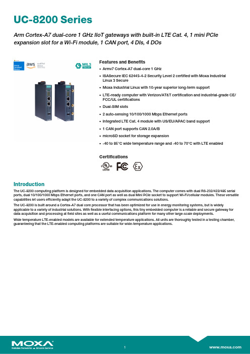
UC-8200SeriesArm Cortex-A7dual-core1GHz IIoT gateways with built-in LTE Cat.4,1mini PCIe expansion slot for a Wi-Fi module,1CAN port,4DIs,4DOsFeatures and Benefits•Armv7Cortex-A7dual-core1GHz•ISASecure IEC62443-4-2Security Level2certified with Moxa IndustrialLinux3Secure•Moxa Industrial Linux with10-year superior long-term support•LTE-ready computer with Verizon/AT&T certification and industrial-grade CE/FCC/UL certifications•Dual-SIM slots•2auto-sensing10/100/1000Mbps Ethernet ports•Integrated LTE Cat.4module with US/EU/APAC band support•1CAN port supports CAN2.0A/B•microSD socket for storage expansion•-40to85°C wide temperature range and-40to70°C with LTE enabledCertificationsIntroductionThe UC-8200computing platform is designed for embedded data acquisition applications.The computer comes with dual RS-232/422/485serial ports,dual10/100/1000Mbps Ethernet ports,and one CAN port as well as dual Mini PCIe socket to support Wi-Fi/cellular modules.These versatile capabilities let users efficiently adapt the UC-8200to a variety of complex communications solutions.The UC-8200is built around a Cortex-A7dual core processor that has been optimized for use in energy monitoring systems,but is widely applicable to a variety of industrial solutions.With flexible interfacing options,this tiny embedded computer is a reliable and secure gateway for data acquisition and processing at field sites as well as a useful communications platform for many other large-scale deployments.Wide temperature LTE-enabled models are available for extended temperature applications.All units are thoroughly tested in a testing chamber, guaranteeing that the LTE-enabled computing platforms are suitable for wide-temperature applications.AppearanceUC-8210UC-8220SpecificationsComputerCPU Armv7Cortex-A7dual-core1GHzDRAM2GB DDR3LSupported OS Moxa Industrial Linux1(Debian9,kernel4.4),2027EOLMoxa Industrial Linux31(Debian11,kernel5.10),2031EOLSee /MILStorage Pre-installed8GB eMMCExpansion Slots MicroSD(SD3.0)socket x13OS is selectable via Moxa Computer Configuration System(CCS)for CTO models.For the model names,see the Ordering Information section of thedatasheet PDF file.Computer InterfaceEthernet Ports Auto-sensing10/100/1000Mbps ports(RJ45connector)x2 Serial Ports RS-232/422/485ports x2,software selectable(DB9male) CAN Ports CAN2.0A/B x1(DB9male)Digital Input DIs x4Digital Output DOs x4USB2.0USB2.0hosts x1,type-A connectorsWi-Fi Antenna Connector UC-8220Models:RP-SMA x2Cellular Antenna Connector UC-8220Models:SMA x2GPS Antenna Connector UC-8220Models:SMA x1Expansion Slots UC-8220-T-LX:mPCIe slot x2UC-8220-T-LX US/EU/AP Models:mPCIe slot x1SIM Format UC-8220Models:NanoNumber of SIMs UC-8220Models:2Buttons Programmable buttonTPM TPM v2.0Ethernet InterfaceMagnetic Isolation Protection 1.5kV(built-in)Security FunctionsHardware-based Security TPM2.0Hardware Root of Trust Secure BootIntrusion Detection Host-based Intrusion DetectionSecurity Tools Security Diagnostic ToolSecurity Event AuditingSecure UpdateDisk Protection LUKS Disk EncryptionRecovery One-step recovery to the last known secure stateDual-system design with automatic failbackReliability Network Keep AliveNetwork Failover and FailbackSerial InterfaceBaudrate300bps to921.6kbpsData Bits7,8Stop Bits1,2Parity None,Even,Odd,Space,MarkFlow Control RTS/CTS,XON/XOFFADDC(automatic data direction control)for RS-485RTS Toggle(RS-232only)Console Port1x4-pin header to DB9console portRS-232TxD,RxD,RTS,CTS,DTR,DSR,DCD,GNDRS-422Tx+,Tx-,Rx+,Rx-,GNDRS-485-2w Data+,Data-,GNDCAN InterfaceNo.of Ports1Connector DB9maleBaudrate10to1000kbpsIndustrial Protocols CAN2.0ACAN2.0BIsolation2kV(built-in)Signals CAN_H,CAN_L,CAN_GND,CAN_SHLD,CAN_V+,GNDDigital InputsConnector Screw-fastened Euroblock terminalDry Contact Off:openOn:short to GNDIsolation3K VDCSensor Type Wet contact(NPN)Dry contactWet Contact(DI to COM)On:10to30VDCOff:0to3VDCDigital OutputsConnector Screw-fastened Euroblock terminalCurrent Rating200mA per channelI/O Type SinkVoltage24VDC nominal,open collector to30VDCCellular InterfaceCellular Standards LTE Cat.4Band Options US Models:LTE Band2(1900MHz)/LTE Band4(1700MHz)/LTE Band5(850MHz)/LTE Band13(700MHz)/LTE Band17(700MHz)UMTS/HSPA850MHz/1900MHzCarrier Approval:Verizon,AT&TEU Models:LTE Band1(2100MHz)/LTE Band3(1800MHz)/LTE Band5(850MHz)/LTE Band7(2600MHz)/LTE Band8(900MHz)/LTE Band20(800MHz)UMTS/HSPA850MHz/900MHz/1900MHz/2100MHzAP Models:LTE Band1(2100MHz)/LTE Band3(1800MHz)/LTE Band5(850MHz)/LTE Band7(2600MHz)/LTE Band8(900MHz)/LTE Band28(700MHz)UMTS/HSPA850MHz/900MHz/1900MHz/2100MHzReceiver Types GPS/GLONASS/GalileoState-of-the-art GNSS solutionAccuracy Position:2.0m@CEP50Acquisition Hot starts:1.1secCold starts:29.94secSensitivity Cold starts:-145dBmTracking:-160dBmTime Pulse0.25Hz to10MHzLED IndicatorsSystem Power x2Programmable x1SIM card indicator x1Wireless Signal Strength Cellular/Wi-Fi x6Power ParametersNo.of Power Inputs Redundant dual inputsInput Voltage12to48VDCPower Consumption10WInput Current0.8A@12VDCReliabilityAlert Tools External RTC(real-time clock)Automatic Reboot Trigger External WDT(watchdog timer)Physical CharacteristicsDimensions UC-8220Models:141.5x120x39mm(5.7x4.72x1.54in)UC-8210Models:141.5x120x27mm(5.7x4.72x1.06in)141.5x120x27mm(5.7x4.72x1.06in)Weight UC-8210Models:560g(1.23lb)UC-8220Models:750g(1.65lb)Housing SECCMetalIP Rating IP30Installation DIN-rail mountingWall mounting(with optional kit)Environmental LimitsOperating Temperature-40to70°C(-40to158°F)Storage Temperature(package included)-40to85°C(-40to185°F)Ambient Relative Humidity5to95%(non-condensing)Shock IEC60068-2-27Vibration2Grms@IEC60068-2-64,random wave,5-500Hz,1hr per axis(without USB devicesattached)Standards and CertificationsEMC EN55032/35EN61000-6-2/-6-4EMI CISPR32,FCC Part15B Class AEMS IEC61000-4-2ESD:Contact:4kV;Air:8kVIEC61000-4-3RS:80MHz to1GHz:10V/mIEC61000-4-4EFT:Power:2kV;Signal:1kVIEC61000-4-6CS:10VIEC61000-4-8PFMFIEC61000-4-5Surge:Power:0.5kV;Signal:1kV Industrial Cybersecurity IEC62443-4-1IEC62443-4-2Hazardous Locations Class I Division2ATEXIECExCarrier Approvals VerizonAT&TSafety UL62368-1EN62368-1Green Product RoHS,CRoHS,WEEEMTBFTime UC-8210-T-LX-S:708,581hrsUC-8220-T-LX:650,836hrsUC-8220-T-LX-US-S/EU-S/AP-S:528,574hrs Standards Telcordia(Bellcore)Standard TR/SRWarrantyWarranty Period5yearsDetails See /warrantyPackage ContentsDevice1x UC-8200Series computerDocumentation1x quick installation guide1x warranty cardInstallation Kit1x DIN-rail kit(preinstalled)1x power jack6x M2.5mounting screws for the cellular module Cable1x console cableDimensions UC-8210UC-8220Ordering Information12UC-8210-T-LX-SDefault:MIL1(-Debian9),2027EOLOrder WithModel UC-8210-T-LX-S(CTO):MIL3(Debian11)Secure/Standard,2031EOLWith MIL3Secure1GHzDual CoreBuilt in––-40to85°CUC-8220-T-LXDefault:MIL1(-Debian9),2027EOLOrder WithModel UC-8220-T-LX(CTO):MIL3(Debian11)Secure/Standard,2031EOLWith MIL3Secure1GHzDual CoreBuilt in Reserved Reserved-40to70°CUC-8220-T-LX-US-SDefault:MIL1(-Debian9),2027EOLOrder WithModel UC-8220-T-LX-US-S(CTO):MIL3(Debian11)Secure/Standard,2031EOLWith MIL3Secure1GHzDual CoreBuilt inUS region LTEmodulepreinstalledReserved-40to70°CUC-8220-T-LX-EU-SDefault:MIL1(-Debian9),2027EOLOrder WithModel UC-8220-T-LX-EU-S(CTO):MIL3(Debian11)Secure/Standard,2031EOLWith MIL3Secure1GHzDual CoreBuilt inEurope regionLTE modulepreinstalledReserved-40to70°CUC-8220-T-LX-AP-SDefault:MIL1(-Debian9),2027EOLOrder WithModel UC-8220-T-LX-AP-S(CTO):MIL3(Debian11)Secure/Standard,2031EOLWith MIL3Secure1GHzDual CoreBuilt inAPAC regionLTE modulepreinstalledReserved-40to70°CUC-8210-T-LX-S(CTO)MIL3(Debian11)Secure orStandard,2031EOLWith MIL3Secure1GHzDual CoreBuilt in––-40to85°CUC-8220-T-LX(CTO)MIL3(Debian11)Secure orStandard,2031EOLWith MIL3Secure1GHzDual Core–Reserved Reserved-40to70°CUC-8220-T-LX-US-S (CTO)MIL3(Debian11)Secure orStandard,2031EOLWith MIL3Secure1GHzDual CoreBuilt inUS region LTEmodulepreinstalledReserved-40to70°C12UC-8220-T-LX-EU-S (CTO)MIL3(Debian11)Secure orStandard,2031EOLWith MIL3Secure1GHzDual CoreBuilt inEurope regionLTE modulepreinstalledReserved-40to70°CUC-8220-T-LX-AP-S (CTO)MIL3(Debian11)Secure orStandard,2031EOLWith MIL3Secure1GHzDual CoreBuilt inAPAC regionLTE modulepreinstalledReserved-40to70°CAccessories(sold separately)Power AdaptersPWR-12150-EU-SA-T Locking barrel plug,12VDC,1.5A,100to240VAC,EU plug,-40to75°C operating temperature PWR-12150-UK-SA-T Locking barrel plug,12VDC,1.5A,100to240VAC,UK plug,-40to75°C operating temperature PWR-12150-USJP-SA-T Locking barrel plug,12VDC1.5A,100to240VAC,US/JP plug,-40to75°C operating temperature PWR-12150-AU-SA-T Locking barrel plug,12VDC,1.5A,100to240VAC,AU plug,-40to75°C operating temperature PWR-12150-CN-SA-T Locking barrel plug,12VDC,1.5A,100to240VAC,CN plug,-40to75°C operating temperature Power WiringCBL-PJTB-10Non-locking barrel plug to bare-wire cableCablesCBL-F9DPF1x4-BK-100Console cable with4-pin connector,1mWi-Fi Wireless ModulesUC-8200-WLAN22-AC Wireless package for UC-8200V2.0or later with Wi-Fi module,2screws,2spacers,1heat sink,1pad AntennasANT-LTEUS-ASM-01GSM/GPRS/EDGE/UMTS/HSPA/LTE,1dBi,omnidirectional rubber-duck antennaANT-LTE-ASM-04BK704to960/1710to2620MHz,LTE omnidirectional stick antenna,4.5dBiANT-LTE-OSM-03-3m BK700-2700MHz,multiband antenna,specifically designed for2G,3G,and4G applications,3m cable ANT-LTE-ASM-05BK704-960/1710-2620MHz,LTE stick antenna,5dBiANT-LTE-OSM-06-3m BK MIMO Multiband antenna with screw-fastened mounting option for700-2700/2400-2500/5150-5850MHzfrequenciesANT-WDB-ARM-02022dBi at2.4GHz or2dBi at5GHz,RP-SMA(male),dual-band,omnidirectional antennaDIN-Rail Mounting KitsUC-8210DIN-rail Mounting Kit DIN-rail mounting kit for UC-8210with4M3screwsUC-8220DIN-rail Mounting Kit DIN-rail mounting kit for UC-8220with4M3screwsWall-Mounting KitsUC-8200Wall-mounting Kit Wall-mounting kit for UC-8200with4M3screws©Moxa Inc.All rights reserved.Updated Jul18,2023.This document and any portion thereof may not be reproduced or used in any manner whatsoever without the express written permission of Moxa Inc.Product specifications subject to change without notice.Visit our website for the most up-to-date product information.。
MAX713中文资料
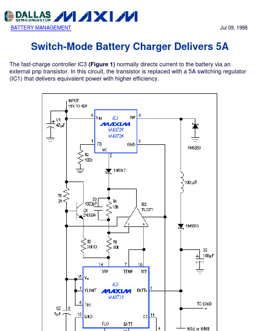
BATTERY MANAGEMENT Jul 09, 1998 Switch-Mode Battery Charger Delivers 5AThe fast-charge controller IC3 (Figure 1) normally directs current to the battery via an external pnp transistor. In this circuit, the transistor is replaced with a 5A switching regulator (IC1) that delivers equivalent power with higher efficiency.Figure 1. By controlling the PWM duty cycle of switching regulator IC1, the fast-charge controller (IC3) makes efficient delivery of the battery's charging current.IC1 is a 5A buck switching regulator whose output is configured as a current source. Its internal power switch (an npn transistor) is relatively efficient because V CE(SAT) is small in comparison with the 15V-to-40V inputs. (For applications that require 2A or less, the low-saturation, non-Darlington power switch of a MAX726 offers better efficiency.)R6 senses the battery-charging current and enables IC3 to generate an analog drive signal at DRV. The signal is first attenuated by the op amp to assure stability by reducing gain in the control loop. It then drives IC1's compensation pin (VC), which gives direct access to the internal PWM comparator. IC3 thus controls the charging current via the PWM duty cycle of IC1. The Q1 buffer provides current to the DRV input.Loop stability is also determined by the feedback loop's dominant pole, set by C4 at the CC terminal of IC3. If you increase the value of the battery filter capacitor (C5), you should make a proportional increase in the value of C4. Lower values, however, assure good transient response. If your application produces load transients during the fast-charge cycle, check the worst-case response to a load step. To assure proper termination of the charge, battery voltage should settle within 2msec to 5mV times N (where N is the number of battery cells). More InformationMAX713:QuickView-- Full (PDF) Data Sheet-- Free Samples。
松下 KX-FLB753CN平台多功能激光一体机 说明书
L 应使本机远离产生电气干扰的装置, 如荧光 灯和电机等。
L 应使本机避开灰尘、 高温和振动。 L 勿将本机暴露在直接阳光照射下。 L 勿在本机上放置重物。 L 勿用湿手触摸插头。
3
安全说明
注意 :
激光放射 L 本机的打印机使用激光。 若进行说明书中未
注明的控制、 调节或操作, 可能会导致危险 的放射。
概述 .................................................................................................................... 9 位置 .................................................................................................................. 10
高的地方。 - 请勿将硒鼓直接暴露在阳光下。
静电 L 为防止静电损坏端口连接器 (并行和
USB)、 ADF插口或机内其他电气组件, 请 在触摸组件之前, 先触摸接地金属表面, 如 并行端口连接器下面的金属部分。
熔融装置 L 熔融装置位于本机内部, 可能会变热。 当取
出卡住的纸张或清洁下部玻璃时不要触摸 它。
常工作。 只能调节使用说明书中包括的控 制部分。 不正确的调节反而会使被授权的 维修中心必须进行更多的修理。 E. 如果本机掉落或机身损坏。 F. 如果本机在性能上发生明显的变化。 14. 在雷雨过程中, 应避免使用电话 (无绳电 话除外)。 否则, 雷电可能会导致远距离电 击。 15. 当附近有煤气泄露时, 请勿使用本机来报告 煤气泄露情况。
Maxon SL-70W系列合成扫描无线电操作说明书

SL-70W Series Synthesized Scanning RadioOperatingInstructionsAbout Your SL-70W Series RadioMaxon's SL-70W Series radios feature 16 channel operation with superior performance and reliability. Operation and functions for Maxon's SL-70W Series radios are described in this manual.We urge you to thoroughly read this manual before operating the radio.Application of some of the functions described in this manual is determined by the system you use. Your Maxon Dealer will program your radio so that you have the greatest number of functions possible relative to your needs.Should you have questions regarding the operation of the radio, please consult your Maxon Dealer.About Maxon America, Inc.Maxon America, Inc. designs and manufactures professional FM two-way radio equipment to serve a wide variety of communication needs. Maxon produces equipment for the Land Mobile Radio and Specialized Mobile Radio markets (business, industrial, government and public safety).Table of ContentsSafety Information................................................................. Unpacking Information.......................................................... SL-70W Series Features.......................................................... Description of Radio Components......................................... Antenna Installation............................................................... Battery Pack Removal / Belt Clip Installation.......................... Battery Charging and Care..................................................... SL-70W Series Operation......................................................Power On-Volume.................................................Transmit.................................................................Receive..................................................................Power Off.............................................................. Status Indicators and Audible Alert Tones............................. Scan Modes.........................................................................Normal Channel Scan...........................................Priority Channel Scan............................................ Other Scanning Features......................................................Look Back.............................................................Scan Channel Delete.............................................CTCSS/DCS Scanning............................................Normal Scan TX....................................................Priority Scan TX.....................................................Priority Only TX....................................................Receive Only Scan................................................ Licensing and Service Information........................................ Recycling / Disposal of Batteries.......................................... Software Copyrights............................................................. Maintenance........................................................................ Limited Warranty.................................................................12 3 4 5 7 7 8 9 9 9 9 10 10 11 11 11 12 12 12 12 12 12 12 12 13 13 14 15 16Safety InformationThe Federal Communications Commission (FCC), with its action in General Docket 79-144, March 13, 1985, has adopted a safety standard for human exposure to Radio Frequency (RF) electromag-netic energy emitted by FCC regulated equipment. Maxon sub-scribes to the same safety standard for the use of its products. Proper operation of this radio will result in user exposure far below the Occupational Safety and Health Act and Federal Communications Commission limits.WARNING - DO NOT hold the radio in such a manner that theantenna is next to, or touching, exposed parts of thebody, especially the face or eyes, while transmitting. WARNING -DO NOT allow children to operate transmitter -equipped radio equipment.CAUTION -DO NOT operate the radio near unshielded electrical blasting caps or in an explosive atmosphere unless itis a type especially designed and qualified for such use. CAUTION - DO NOT press and hold the transmit switch (P-T-T)when not actually wishing to transmit.NOTE: This radio operates in FCC regulated frequency bands. All radios must be licensed by the FCC before use. Because this radio contains a transmitter, Federal law prohibits unauthorized use or adjustments of this radio.2Unpacking InformationRemove and carefully inspect the contents of your package(s) for the following items:RadioBattery PackAntennaBelt ClipOperating InstructionsIf any items are missing, please contact your Dealer or Maxon.3SL-70W Series Features•Wideband operation•Channel scan•Priority channel scan•Look back channel•CTCSS/DCS tone signalling•Busy channel lockout•Time-out timer•Programmable 12.5 to 25 kHz channel spacing (per channel)•HI / LO power switch provides full 5 Watts or battery saving ~1.5 Watts output4Description of Radio Components1)Antenna Receptacle2)Accessory Jack: Used with optional speaker microphone ormini-VOX unit. May also be used for an external 8 Ohmspeaker or an earphone.3)On / Off - Volume Control4)Channel Selector Knob5)BUSY / TX / BT Indicator: Tri-color Light Emitting Diode (LED)identifies radio status.6)HI/LO "TX" Power Switch: Selects radio output power.7)Monitor Button8)P-T-T Bar9)Speaker10)Microphone11)Slide-on Battery Pack: 600 or 1200 mAh battery packs.12)Battery Charge Contacts56Antenna InstallationFasten the antenna to the radio by turning the antenna clockwise into the receptacle on top of the radio.Battery Pack Removal / Belt Clip InstallationThe battery must be removed from the radio body to install the belt clip. Remove the slide-on battery pack by placing your thumb under the latch on the side of the radio (A). Lift upward while sliding battery away from your thumb (B). Insert top portion of belt clip into recessed hole located on rear top of radio body (C). Position bottom of belt clip against radio back (D). Re-install battery by aligning "rails" on battery with radio body and sliding firmly toward latch side of radio (E). Once the battery is installed, the belt clip cannot be removed without again removing the battery pack.7Battery Charging and CareTo ensure peak performance from your radio, the battery pack must be fully charged. Proper care and charging will allow maximum performance and life of your battery pack.The SA-1120 Pedestal Charger, available optionally for your SL-70W Series Radio, offers convenient charging capabilities. The charging cycle with this charger is overnight (12-16 hours). For longest battery life try to avoid charging the radio for more than 24 hoursat a time.The optional SA-1125 Desktop Quick Charger provides "one hour" charging and normal "slow" charging to two units simultaneously. The high capacity 1200 mAh battery pack will take longer to fully charge.See accompanying instructions included with these chargers for more information.To receive maximum performance from your radio and battery pack, periodically completely discharge and recharge the battery pack.8SL-70W Series OperationsPower On-VolumeTurn the radio on by rotating the on/off - volume control clockwise until you hear a click and the self test "alert" tone.TransmitCAUTIONOPERATION OF THE TRANSMITTER WITHOUTA PROPER ANTENNA INSTALLED MAY RESULT INPERMANENT DAMAGE TO THE RADIO1) Press the monitor button to monitor the channel for activity. Toavoid interrupting another user, make sure the channel is clearbefore you begin transmitting.NOTE: Federal Communications Commission Rules and Regulations require that you monitor a channel for activity before transmitting. NOTE: The tri-color LED located on the top panel can help with channel monitoring. It will glow amber if RF activity is present; or green if the transmission has a CTCSS or DCS tone that matches a tone programmed for receive in your radio. When this LED is not illuminated, the radio is indicating a "clear" channel.2)When the channel is clear, hold the radio upright with the antenna vertical and the front grille area about 2-3 inches fromthe mouth, keeping the antenna away from the face and eyes. Press and hold the P-T-T bar on the side of the radio, and speak slowly and clearly into the grille area.NOTE: The LED will glow red when transmitting. This indicator should be on continuously while the P-T-T bar is being pressed and the radio is transmitting. Should the red LED be "flashing", the battery needs to be recharged and transmission will cease. Recharge the battery before attempting more than one transmission. ReceiveWhen you have finished transmitting, release the P-T-T to receive. 9Power OffWhen finished transmitting, receiving, monitoring, etc., turn the radio off by rotating the on/off-volume control fully counter-clockwise, to the detent position.Status Indicators and Audible Alert TonesYour SL-70W Series has a sophisticated microprocessor control which provides a series of audible alert tones.Upon initial power up, a quick melody indicates that the self-test of the microprocessor functions has been completed satisfactorily. A series of tones may be sounded with any of the following conditions:• Attempt to transmit on a channel set for receive only• Attempt to transmit on a channel that is already in use when busy channel lockout has been programmed into the radio *• Transmitting time has exceeded time-out timer programmed length *• Low battery condition• Selecting a channel with no programmed frequency* Indicates a function that is initially programmed into the radio by your Maxon Dealer.NOTE:All audible tones can be programmed off for silent operation.Scan ModesScanning is a Dealer programmable feature that allows you to monitor a number of channels. Your Dealer will help you define a channel "scan list" to be programmed into a scan channel (any channel, 1-16). Once that channel location is selected, scan is initiated.Normal Channel ScanOnce the scan list is programmed you can initiate scan. Simply move the channel selector knob to the scan channel positionand the radio will start to scan. The top panel LED can beprogrammed to flash green as the radio is scanning.If a conversation is detected on any of the channels in the scan list, the radio will stop on that channel and you will be able to hear the conversation. If programmed for normal scan TX youwill be able to transmit on that active channel during theprogrammable scan delay time. The scan delay time is theamount of time the radio will stay on that channel once activity has ceased (Dealer programmable, 4-7 seconds is typical). The radio will resume scanning once the scan delay time hasexpired. Scanning will continue until the channel is changed.Priority Channel ScanA single channel may be programmed as the "Priority" channel.The radio will constantly monitor this channel while scanningand when the radio has stopped on an active channel. If a callis detected on the "Priority" channel, the radio will automati-cally move to, and remain on, the "Priority" channel for as long as the priority conversation takes place. "Priority" channelactivity takes precedence over all other conversations.NOTE: "Priority" channel scan and "look back" require that the radio leave the active channel for a fraction of a second (atregular intervals) to check the priority channel for a message.Depending upon how the radio is programmed (scan speed,etc.) this may or may not be noticeable as "breaks" on theactive channel for that same fraction of a second.11Other Scanning Features•Look Back: Any channel, when not in the scan mode, can be programmed to "look back" at the "Priority" channel. Thisfeature is ideal for those who do not need scan as defined above, but want to make sure that they never miss a call on the "Priority" channel if another channel has been selected. Once a "look back" channel has been selected, the radio will periodically "look back" at the "Priority" channel. If activity is detected on the "Priority" channel, the radio will move to that channel for as long as it remains active.•Scan Channel Delete: To temporarily delete a channel from the scan list, simply press the monitor button while scanning and stopped on the channel to be deleted. This will remove that channel from the scan list until the channel is changed or the radio's power is reset. When power is restored or the scan list channel position is again selected, the original Dealer pro-grammed scan list will be activated.•CTCSS/DCS Scanning: The SL-70W can be programmed by your Dealer to scan for tone. This will help block out unwanted calls.• Normal Scan TX: Allows a transmission only after a call is received,depending on the programmed scan delay time. After the scan resumes, and a transmission is made, the radio will sound an alarm (two beeps) and will not allow a transmission.• Priority Scan TX: Allows a transmission after a call is received depending on programmed scan delay time. The transmission will be made on the channel that the call was received. After the scan resumes, if a transmission is made, the radio will transmit on the programmed priority channel.•Priority Only TX: Allows a transmission on the priority channel when scanning and not stopped on an active channel. It can also be programmed to always transmit on the priority channel if scanning or stopped on an active channel.•Receive Only Scan: This allows only reception. If a transmission is made at any time, the radio will sound an alarm (two beeps) and will not allow the transmission.12Licensing and Service InformationFCC LicensingThe Federal Communications Commission requires that the operator of this radio be properly licensed under the applicable Part and/or Parts of the FCC Rules and Regulations.Consult with your Maxon Dealer, or contact the nearest FCC Field Office for information about obtaining a license.ServiceDo not tamper with internal adjustments. Damage to the equipment and/or improper operation may result. There are no user serviceable items inside the radio.It is recommended that you return your radio to a qualified Maxon Dealer for any service or repairs.Recycling/Disposal of BatteriesThe U.S. Environmental Protection Agency (EPA) classifies used Ni-Cd batteries as hazardous waste, unless certain exemptions apply. The battery should be recycled at the end of its useful life. Under various state or local laws, such batteries must be recycled or disposed of properly and cannot be dumped in landfills or incinerators.Maxon America, Inc. fully endorses and encourages the recyclingof Ni-Cd batteries. A national program to collect and recycle usedNi-Cd batteries is being implemented by the Rechargeable Battery Recycling Corporation (RBRC ™). This program is being funded through the use of license fees paid by the battery and product manufacturers to place the RBRC™ Seal on the batteries.The following is a list of recycling facilities where the batteriescan be shipped to be recycled. Contact these facilities for proper packaging and shipping guidelines.13INMETCO245 Portersville Road Ellwood City, PA 16117 TEL: (412) 758-2802 FAX: (412) 758-9311Within Minnesota,U.S. Filter Recovery Services, Inc.2430 Rose PlaceRoseville, MN 55113TEL: (800) 732-3226FAX: (612) 788-0312Within New Jersey,Wade Environmental Industries,Battery Division293-C Jackson RoadAtco, NJ 08004TEL: (609) 767-2760FAX: (609) 767-0698Software CopyrightsThe Maxon products described in this operating instruction manual may include copyrighted Maxon software programs stored in semi-conductor memories or other media. Laws in the United States and other countries preserve for Maxon certain exclusive rights for copy-righted software programs, including the exclusive right to copy or reproduce in any form the copyrighted software program. Accordingly, the copyrighted Maxon software programs contained in the Maxon products described in this operating instruction manual may not be copied or reproduced without the express written permission of Maxon. Furthermore, the purchase ofMaxon products shall not be deemed to grant either directly orby implication, estoppel, or otherwise, any license under the copyrights, patents or patent applications of Maxon, except for normal non-exclusive royalty free license to use that arises by operation of law in the sale of a product.14MaintenanceYour SL-70W Series Radio is designed to be maintenance free. To keep your radio in good working condition:Clean external surfaces with a clean cloth dampened in a solution of dishwasher detergent diluted in water. Apply the solution sparingly to avoid any moisture leaking into cracks and crevices. Do not submerge the radio. Use a non-metallic brush to dislodge stubborn particles, if necessary. Dry the surface thoroughly with a soft, lint free cloth.DO NOT use solvents or spirits for cleaning - they may permanently damage the housing.Clean the battery contacts on the bottom of the radio with a lint free cloth to remove dirt, grease, or other foreign material that may impede good electrical contact15Limited WarrantyMaxon America, Inc. ("Maxon") warrants the Maxon Product manufactured by it against defects in material and workmanship under normal use and service for a period of two (2) years from the date of delivery to the original end user, provided that the user has complied with the requirements stated herein. This warranty is not assignable or transferable. Maxon is not responsible for any ancillary equipment which is attached or used in connection with this product.Maxon shall have no obligation to make repairs or to cause replacement required which result from normal wear and tear or necessitated in whole or in part by catastrophe, fault or negligence of the user, improper or unauthorized alterations, repairs to the Product, use of the Product in a manner for which it was not designed, or by causes external to the Product. This warranty is void if the serial number is altered, defaced or removed.Maxon's sole obligation hereunder shall be to repair or replace the Product covered in the above warranty.To receive warranty service, deliver or send the Product, transporta-tion and insurance prepaid, to the place of purchase along with your proof of purchase. Alternatively, call 1-800-821-7848 for other locations or authorization to return the product directly to Maxon. THE EXPRESS WARRANTIES CONTAINED HEREIN ARE IN LIEU OF ALL OTHER WARRANTIES, EITHER EXPRESSED OR IMPLIED OR STATUTORY, INCLUDING, WITHOUT LIMITATION, ANY WARRANTY OF MERCHANTABILITY OR FITNESS FOR A PARTICULAR PURPOSE.FOR ANY PRODUCT WHICH DOES NOT COMPLY WITH THE WARRANTY SPECIFIED, THE SOLE REMEDY WILL BE REPAIR OR REPLACEMENT. IN NO EVENT WILL MAXON BE LIABLE TO THE BUYER OR ITS CUSTOMERS FOR ANY DAMAGES, INCLUDING ANY SPECIAL, INCIDENTAL, INDIRECT OR CONSEQUENTIAL DAMAGES, OR FOR THE LOSS OF PROFIT, REVENUE OR DATA ARISING OUT OF THE USE OF OR THE INABILITY TO USE THE PRODUCT.This warranty is void for sales and deliveries outside of the United States.16Maxon America, Inc.Business Radio Division10828 NW Air World DriveKansas City, Missouri 64153816/891-6320, FAX: 816/891-8815P/N: 680-090-0004。
MAX1978中文数据手册

用于Peltier模块的集成温度控制器概论MAX1978 / MAX1979是用于Peltier热电冷却器(TEC)模块的最小, 最安全, 最精确完整的单芯片温度控制器。
片上功率FET和热控制环路电路可最大限度地减少外部元件, 同时保持高效率。
可选择的500kHz / 1MHz开关频率和独特的纹波消除方案可优化元件尺寸和效率, 同时降低噪声。
内部MOSFET的开关速度经过优化, 可降低噪声和EMI。
超低漂移斩波放大器可保持±0.001°C的温度稳定性。
直接控制输出电流而不是电压, 以消除电流浪涌。
独立的加热和冷却电流和电压限制提供最高水平的TEC保护。
MAX1978采用单电源供电, 通过在两个同步降压调节器的输出之间偏置TEC, 提供双极性±3A输出。
真正的双极性操作控制温度, 在低负载电流下没有“死区”或其他非线性。
当设定点非常接近自然操作点时, 控制系统不会捕获, 其中仅需要少量的加热或冷却。
模拟控制信号精确设置TEC 电流。
MAX1979提供高达6A的单极性输出。
提供斩波稳定的仪表放大器和高精度积分放大器, 以创建比例积分(PI)或比例积分微分(PID)控制器。
仪表放大器可以连接外部NTC或PTC热敏电阻, 热电偶或半导体温度传感器。
提供模拟输出以监控TEC温度和电流。
此外, 单独的过热和欠温输出表明当TEC温度超出范围时。
片上电压基准为热敏电阻桥提供偏置。
MAX1978 / MAX1979采用薄型48引脚薄型QFN-EP 封装, 工作在-40°C至+ 85°C温度范围。
采用外露金属焊盘的耐热增强型QFN-EP封装可最大限度地降低工作结温。
评估套件可用于加速设计。
应用光纤激光模块典型工作电路出现在数据手册的最后。
WDM, DWDM激光二极管温度控制光纤网络设备EDFA光放大器电信光纤接口ATE特征♦尺寸最小, 最安全, 最精确完整的单芯片控制器♦片上功率MOSFET-无外部FET♦电路占用面积<0.93in2♦回路高度<3mm♦温度稳定性为0.001°C♦集成精密积分器和斩波稳定运算放大器♦精确, 独立的加热和冷却电流限制♦通过直接控制TEC电流消除浪涌♦可调节差分TEC电压限制♦低纹波和低噪声设计♦TEC电流监视器♦温度监控器♦过温和欠温警报♦双极性±3A输出电流(MAX1978)♦单极性+ 6A输出电流(MAX1979)订购信息* EP =裸焊盘。
MAXIM MAX7320 说明书
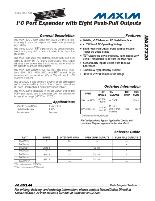
General DescriptionThe MAX7320 2-wire serial-interfaced peripheral fea-tures eight push-pull outputs with selectable power-up logic states.The +5.5V tolerant RST input clears the serial interface,terminating any I 2C communication to or from the MAX7320.The MAX7320 uses two address inputs with four-level logic to allow 16 I 2C slave addresses. The slave address also determines the power-up state level for the outputs in groups of four ports.The MAX7320 supports hot insertion. The serial inter-face SDA, SCL, AD0, AD2, and RST remain high impedance in power-down (V+ = 0V) with up to +6V asserted on them.The MAX7320 is one device in a family of pin-compatible port expanders with a choice of input ports, open-drain I/O ports, and push-pull output ports (see Table 1).The MAX7320 is available in 16-pin QSOP and 16-pin TQFN packages, and is specified over the automotive temperature range (-40°C to +125°C).ApplicationsFeatures♦400kHz, +5.5V-Tolerant I 2C Serial Interface♦+1.71V to +5.5V Operating Voltage♦Eight Push-Pull Output Ports with Selectable Power-Up Logic States ♦RST Clears the Serial Interface, Terminating Any Serial Transaction to or from the MAX7320♦AD0 and AD2 Inputs Select from 16 Slave Addresses ♦Low 0.6µA (typ) Standby Current ♦-40°C to +125°C Temperature RangeMAX7320I 2________________________________________________________________Maxim Integrated Products 119-3879; Rev 0; 10/05For pricing, delivery, and ordering information,please contact Maxim/Dallas Direct!at 1-888-629-4642, or visit Maxim’s website at .Ordering InformationPin Configurations, Typical Application Circuit, and Functional Diagram appear at end of data sheet.+Denotes lead-free package.*Second source to PCF8574.**Second source to PCF8574A.Cell Phones/PDAs Satellite Radios NotebooksAutomotive RAID ServersM A X 7320I 2C Port Expander with Eight Push-Pull Outputs 2_______________________________________________________________________________________ABSOLUTE MAXIMUM RATINGSStresses beyond those listed under “Absolute Maximum Ratings” may cause permanent damage to the device. These are stress ratings only, and functional operation of the device at these or any other conditions beyond those indicated in the operational sections of the specifications is not implied. Exposure to absolute maximum rating conditions for extended periods may affect device reliability.(All voltages referenced to GND.)Supply Voltage V+....................................................-0.3V to +6V SCL, SDA, AD0, AD2, RST .......................................-0.3V to +6V O0–07...............................................................0.3V to V+ + 0.3V 00–07 Output Current.......................................................±25mA SDA Input Current..............................................................10mA Total V+ Current..................................................................50mA Total GND Current ...........................................................100mAContinuous Power Dissipation (T A = +70°C)16-Pin QSOP (derate 8.3mW/°C over +70°C)..............667mW 16-Pin Thin QFN (derate 15.6mW/°C over +70°C)....1250mW Operating Temperature Range .........................-40°C to +125°C Junction Temperature......................................................+150°C Storage Temperature Range.............................-65°C to +150°C Lead Temperature (soldering, 10s).................................+300°CELECTRICAL CHARACTERISTICSMAX7320I 2C Port Expander with Eight Push-Pull Outputs_______________________________________________________________________________________3PORT AND TIMING CHARACTERISTICSTIMING CHARACTERISTICSNote 3:A master device must provide a hold time of at least 300ns for the SDA signal (referred to V IL of the SCL signal) to bridgethe undefined region of SCL’s falling edge.Note 4:C b = total capacitance of one bus line in pF. t R and t F measured between 0.3 x V+ and 0.7 x V+, I SINK ≤6mA.Note 5:Input filters on the SDA and SCL inputs suppress noise spikes less than 50ns.M A X 7320I 2C Port Expander with Eight Push-Pull OutputsTypical Operating Characteristics(T A = +25°C, unless otherwise noted.)0.40.21.00.80.61.21.41.81.62.0-40-105-25203550658095110125STANDBY CURRENT vs. TEMPERATURETEMPERATURE (°C)S T A N D B Y C U R R E N T (μA )201040305060-40-10520-253550658095110125SUPPLY CURRENT vs. TEMPERATURETEMPERATURE (°C)S U P P L Y C U R R E N T (μA )OUTPUT VOLTAGE LOW vs. TEMPERATURETEMPERATURE (°C)O U T P U T V O L T A G E L O W (V )-40-25-1052035506580951101250.050.100.150.200.250.300.350.400.450.50OUTPUT VOLTAGE HIGH vs. TEMPERATURETEMPERATURE (°C)O U T P U T V O L T A G E H I G H (V )-40-25-105203550658095110125123456Pin DescriptionDetailed Description MAX7319–MAX7329 Family Comparison The MAX7319–MAX7323 family consists of five pin-compatible, eight-port expanders. Each version is opti-mized for different applications. The MAX7328 and MAX7329 are second sources to the PCF8574 and PCF8574A.The MAX7324–MAX7327 family consists of four pin-compatible, 16-port expanders that integrate the func-tions of the MAX7320 and one of either the MAX7319, MAX7321, MAX7322, or MAX7323.Functional OverviewThe MAX7320 is a general-purpose port expander operating from a +1.71V to +5.5V supply that provideseight push-pull output ports. The MAX7320 is rated tosink a total of 100mA and source a total of 50mA fromall eight combined outputs.The MAX7320 is set to one of 16 I2C slave addresses(0x50 to 0x5F) using address select inputs AD0 and AD2,and is accessed over an I2C serial interface up to400kHz. Note the MAX7320 offers a different range of I2Cslave addresses than the MAX7319, MAX7321,MAX7322, and MAX7323 (these expanders use the address range 0x60 to 0x6F).MAX7320I2C Port Expander with Eight Push-Pull Outputs _______________________________________________________________________________________5M A X 7320I 2C Port Expander with Eight Push-Pull Outputs 6_______________________________________________________________________________________hung bus, terminating any serial transaction to or from the MAX7320.When the MAX7320 is read through the serial interface, the actual logic states at the ports are read back. Output port power-up logic states are selected by the address select inputs AD0 and AD2. Ports default to logic-high or logic-low on power-up in groups of four (see Table 3).RST Input The RST input voids any I2C transaction involving the MAX7320 and forces the MAX7320 into the I2C STOP condition. A reset does not change the contents of the output register. RST is overvoltage tolerant to +5.5V.Standby Mode When the serial interface is idle, the MAX7320 automat-ically enters standby mode, drawing minimal supply current.Slave Address and Power-UpDefault Logic States Address inputs AD0 and AD2 determine the MAX7320 slave address and set the power-up output logic states. Power-up logic states are set in groups of four (see Table 3). The MAX7320 uses a different range of slave MAX7322, and MAX7323 (110xxxx).The MAX7320 slave address is determined on each I2C transmission, regardless of whether the transmission is actually addressing the MAX7320. The MAX7320 distin-guishes whether address inputs AD0 and AD2 are con-nected to SDA or SCL instead of fixed logic levels V+or GND during this transmission. This means that theMAX7320 slave address can be configured dynamical-ly in the application without cycling the device supply.On initial power-up, the MAX7320 cannot decode the address inputs AD0 and AD2 fully until the first I2C transmission. AD0 and AD2 initially appear to be con-nected to V+ or GND. This is important because the address selection determines the power-up logic levelsof the output ports. However, at power-up, the I2C SDAand SCL bus interface lines are high impedance at thepins of every device (master or slave) connected to thebus, including the MAX7320. This is guaranteed as partof the I2C specification. Therefore, address inputs AD0and AD2 that are connected to SDA or SCL normally appear at power-up to be connected to V+. The power-up output state selection logic uses AD0 to select the power-up state for ports O3–O0, and uses AD2 toselect the power-up state for ports O7–O4. The rule isthat a logic-high, SDA, or SCL connection selects aMAX7320I2C Port Expander with Eight Push-Pull Outputs _______________________________________________________________________________________7 Table 3. MAX7320 Address MapM A X 7320logic-high power-up state, and a logic-low selects a logic-low power-up state for each set of four ports (see Table 3). The output power-up logic level configuration is correct for a standard I 2C configuration, where SDA or SCL appear to be connected to V+ by the external I 2C pullups.There are circumstances where the assumption that SDA = SCL = V+ on power-up is not true; for example,in true hot-swap applications in which there is legiti-mate bus activity during power-up. Also, if SDA and SCL are terminated with pullup resistors to a different supply voltage than the MAX7320’s supply, and if that pullup supply rises later than the MAX7320’s, then SDA or SCL may appear at power-up to be connected to GND. In such applications, use the four address combi-nations that are selected by connecting address inputs AD0 and AD2 to GND or V+ (shown in bold in Table 3).These selections are guaranteed to be correct at power-up, independent of SDA and SCL behavior. If one of the other 12 address combinations is used, be aware that unexpected port power-up default states may occur until the first I 2C transmission (to any device,not necessarily the MAX7320).Port OutputsWrite one byte to the MAX7320 to set all output port states simultaneously.Serial InterfaceSerial-AddressingThe MAX7320 operates as a slave that sends and receives data through an I 2C interface. The interface uses a serial data line (SDA) and a serial clock line (SCL) to achieve bidirectional communication between master(s) and slave(s). A master initiates all data trans-fers to and from the MAX7320, and generates the SCL clock that synchronizes the data transfer (Figure 1).SDA operates as both an input and an open-drain output.A pullup resistor, 4.7k Ω (typ), is required on SDA. SCL operates only as an input. A pullup resistor, 4.7k Ω (typ),is required on SCL if there are multiple masters on the 2-wire interface, or if the master in a single-master system has an open-drain SCL output.E ach transmission consists of a START condition sent by a master, followed by the MAX7320’s 7-bit slave address plus R/W bit, one or more data bytes, and finally a STOP condition (Figure 2).START and STOP ConditionsBoth SCL and SDA remain high when the interface is not busy. A master signals the beginning of a transmis-sion with a START (S) condition by transitioning SDA from high to low while SCL is high. When the master has finished communicating with the slave, the master issues a STOP (P) condition by transitioning SDA from low to high while SCL is high. The bus is then free for another transmission (Figure 2).Bit TransferOne data bit is transferred during each clock pulse.The data on SDA must remain stable while SCL is high (Figure 3).I 2C Port Expander with Eight Push-Pull Outputs 8_______________________________________________________________________________________Figure 1. 2-Wire Serial-Interface Timing DetailsFigure 2. START and STOP ConditionsAcknowledgeThe acknowledge bit is a clocked 9th bit the recipient uses to acknowledge receipt of each byte of data (Figure 4). Each byte transferred effectively requires 9bits. The master generates the ninth clock pulse, and the recipient pulls down SDA during the acknowledge clock pulse, such that the SDA line is stable low during the high period of the clock pulse. When the master is transmitting to the MAX7320, the device generates the acknowledge bit because the MAX7320 is the recipi-ent. When the MAX7320 is transmitting to the master,the master generates the acknowledge bit because the master is the recipient.Slave AddressThe MAX7320 has a 7-bit slave address (Figure 5). The 8th bit following the 7-bit slave address is the R/W bit. It is low for a write command, and high for a read command.The 1st (A6), 2nd (A5), and 3rd (A4) bits of the MAX7320 slave address are always 1, 0, and 1.Connect AD0 and AD2 to GND, V+,SDA, or SCL to select the slave address bits A3, A2, A1, and A0. The MAX7320 has 16 possible slave addresses (Table 3),allowing up to 16 MAX7320 devices on an I 2C bus.Note the MAX7320 offers a different range of I 2C slave addresses from the MAX7319, MAX7321, MAX7322 and MAX7323, for which 1st (A6), 2nd (A5), and 3rd (A4)bits of the slave address are always 1, 1, and 0.Accessing the MAX7320A single-byte read from the MAX7320 returns the sta-tus of the eight output ports, read back as inputs.A 2-byte read repeatedly returns the status of the eight output ports, read back as inputs.A multibyte read (more than 2 bytes before the I 2C STOP bit) repeatedly returns the status of the eight out-put ports, read back as inputs.A single-byte write to the MAX7320 sets the logic state of all eight outputs.A multibyte write to the MAX7320 repeatedly sets the logic state of all eight outputs.Reading from the MAX7320A read from the MAX7320 starts with the master trans-mitting the MAX7320’s slave address with the R/W bit set high. The MAX7320 acknowledges the slave address, and samples the logic state of the output ports during the acknowledge bit. The master can read one or more bytes from the MAX7320 and then issue a STOP condition (Figure 6). The MAX7320 transmits thecurrent port data, read back from the actual port out-puts (not the port output latches) during the acknowl-edge. If a port is forced to a logic state other than its programmed state, the read back reflects this. If driving a capacitive load, readback port level verification algo-rithms may need to take the RC rise/fall time into account.Typically, the master reads one byte from the MAX7320,then issues a STOP condition (Figure 6). However, the master can read 2 or more bytes from the MAX7320,then issue a STOP condition. In this case, the MAX7320resamples the port outputs during each acknowledge and transmits the new data each time.Writing to the MAX7320A write to the MAX7320 starts with the master transmit-ting the MAX7320’s slave address with the R/W bit set low. The MAX7320 acknowledges the slave address and samples the ports during the acknowledge bit. The master can transmit one or more bytes of data. The MAX7320 acknowledges each subsequent byte of data and updates the output ports until the master issues a STOP condition (Figure 7).MAX7320I 2C Port Expander with Eight Push-Pull Outputs_______________________________________________________________________________________9Figure 3. Bit TransferFigure 4. AcknowledgeM A X 7320I 2C Port Expander with Eight Push-Pull Outputs 10______________________________________________________________________________________Figure 5. Slave AddressFigure 6. Reading the MAX7320Figure 7. Writing to the MAX7320MAX7320I 2C Port Expander with Eight Push-Pull Outputs______________________________________________________________________________________11Applications InformationHot InsertionSDA, SCL, AD0, AD2, and RST are overvoltage protect-ed to +6V independent of V+. This allows the MAX7320to be operated from a lower supply voltage, such as +3.3V, while the I 2C interface is driven from a higher logic level, such as +5V.E ach of the output ports, O0–O7, has a protection diode to V+ and to GND (Figure 8). When a port output is driven to a voltage higher than V+ or lower than GND, the appropriate protection diode clamps the out-put to a diode drop above V+ or below GND. When the MAX7320 is powered down (V+ = 0V), each output port appears as a diode connected to GND (Figure 8).Power-Supply ConsiderationsThe MAX7320 operates with a supply voltage of +1.71V to +5.5V over the -40°C to +125°C temperature range.Bypass V+ to GND with a ceramic capacitor of at least 0.047µF as close to the device as possible. For the TQFN version, additionally connect the exposed pad to GND.Figure 8. Output Port StructureM A X 7320I 2C Port Expander with Eight Push-Pull Outputs 12______________________________________________________________________________________Compatibility with MAX6965, MAX7315,and MAX7316The MAX7320 is subset pin compatible with the MAX6965, MAX7315, and MAX7316. The pin differ-ences are shown in Table 4. The MAX7320 is not soft-ware compatible with MAX6965, MAX7315, or MAX7316. In many cases it is possible to design a PC board to work with all these port expanders, providing design flexibility.Pin ConfigurationsChip InformationPROCESS: BiCMOS Connect EP to GNDTypical Application CircuitMAX7320I 2C Port Expander with Eight Push-Pull OutputsPackage Information(The package drawing(s) in this data sheet may not reflect the most current specifications. For the latest package outline information,go to /packages .)M A X 7320I 2C Port Expander with Eight Push-Pull Outputs Maxim cannot assume responsibility for use of any circuitry other than circuitry entirely embodied in a Maxim product. No circuit patent licenses are implied. Maxim reserves the right to change the circuitry and specifications without notice at any time.14____________________Maxim Integrated Products, 120 San Gabriel Drive, Sunnyvale, CA 94086 408-737-7600©2005 Maxim Integrated ProductsPrinted USAis a registered trademark of Maxim Integrated Products, Inc.Package Information (continued)(The package drawing(s) in this data sheet may not reflect the most current specifications. For the latest package outline information,go to /packages .)。
最低静态电流的超小尺寸降压转换器

新品发布NEW PRODUCTS今日电子 · 2018年5月 · 外带来新的层面,例如,混光。
整合式M O S F E T额定60V,使A L8862成为可行的解决方案,可用于更高功率的输出应用。
利用Diodes公司的专有技术,M O S F E T也具备仅0.4Ω的超低R D S(O N),能在缩减外部零件需求的同时展现出高效率。
亦针对短路或开路可能造成的故障情形提供完整保护,同时包含了过热保护。
Diodes Incorporated线性LED控制器A L5814、A L5817、A L5815及AL5816线性LED控制器,为LED灯条提供可调光和可调节的驱动电流,效率高达80%以上。
A L58x x系列提供物料列表(B O M)成本低廉的解决方案,适用于商业和工业领域的各项产品应用,包括广告牌、仪器照明、家电内部照明、建筑细部照明,以及一般智能照明设备。
这些装置的输入范围为4.5~60V,无须电感,可保持良好的E M I效能,使系统整合更简单。
此外,相较于其他设计,外部功率晶体管可使内部功耗降至最低。
A L58x x系列可提供高达15m A 的电流给外部MOSFET或双极晶体管,以驱动LED灯条。
LED驱动电流由一个外部电阻配置,具有4%的参考电压准确度,以及出色的温度稳定性。
不仅如此,AL5815与AL5816装置支持PWM调光功能,A L5814与A L5817装置则同时支持模拟和PWM调光功能。
保护功能包括过温保护及输入欠压锁定。
A L5814及A L5817装置也利用VFAULT脚位提供「LED 开回路」保护功能,以及L E D 热回流保护。
A L58x x系列线性控制器提供良好的E M I效能,而广泛的工作温度范围(-40~+105℃)使其适用于恶劣环境。
Diodes Incorporated超小电源模块MAXM17532和MAXM15462超小尺寸(2.6mm×3.0mm×1.5mm)、集成式DC-DC电源模块是Maxim喜马拉雅电源方案专有组合的一部分,适用于工业、医疗健康、通信和消费市场。
[VIP专享]MAX_线号打印机说明书
![[VIP专享]MAX_线号打印机说明书](https://img.taocdn.com/s3/m/34e1d17eb90d6c85ed3ac645.png)
1.目的对公司线号打印机使用做指导说明。
2.范围适用于公司线号打印机。
3.基本操作3.1 首先打开卡匣盖,装入所需的材料。
接着,关上卡匣盖,打开电源。
3.2 出现选择印刷物的画面时,用上下左右选择键,设定“印刷物”和“尺寸”。
设定完成后,按Enter键,出现输入画面。
注意:当要变更印刷物时,请关闭电源,重新设定。
3.3 套管印字3.3.1 根据要求按步骤3.2选择好印刷物为套管和合适的尺寸。
3.3.2 出现输入画面,确实将Lock键打开ON,按左右选择键,将光标移至 P的下面。
3.3.3 按PITCH键来设定“段落长度”,按左右键选择要求的长度。
注意:也可以利用数字键来直接输入。
设定完成后,按Enter键。
3.3.7 按PRT键来设定“连续”,可按左右选择键来选择所需连续值。
指的是连续出现相同段落。
设定完成后,按Enter键完成。
3.3.8 按左右选择键,将光标移到B的后面,然后输入要求打印的内容。
在按BLOCK键产生一个新的段落。
输入完成按Enter键。
3.3.9 按PRINT键来激活印刷。
出现印刷范围设定屏幕,如不需更改数据,请直接按Enter键。
3.3.10 出现印刷全长画面,如不需改变数据。
请直接按Enter键。
开始印刷。
3.4 贴纸印字3.4.1根据要求按步骤3.2选择好印刷物为贴纸和要求尺寸。
3.4.2其余步骤同套管印字3.5 使用功能3.5.1 字体尺寸在光标停留的段落上,按SIZE键,出现文字尺寸设定画面,按左右选择键选择文字尺寸的数值;按向下选择键,将光标移到“自动”栏,按左右键,选择“OFF”。
按Enter完成设定.注意:只有在“自动”被选择到“OFF”时,字体大小设定才有效。
3.5.2 文字宽度在光标的位置设定“文字宽度”,按WIDTH键,出现印字方向设定画面;按左右选择键选择文字宽度的设定值,按Enter完成设定。
3.5.3 字距/行距设定按C/SPC键,出现字距/行距设定画面;按左右选择键选择“字距”的设定值。
HT7530中文资料
HT75XXHigh Driver RegulatorSelection TablePart No.Output VoltageToleranceHT7530 3.0V ±5%HT7533 3.3V ±5%HT7536 3.6V ±5%HT7544 4.4V ±5%HT7550 5.0V ±5%HT75808.0V±5%1May 2,2000Features·Low power consumption ·Low voltage drop·Low temperature coefficient ·High input voltage (up to 24V)·High output current :100mA (P d £250mW)·TO-92and SOT-89packageApplications·Battery-powered equipment ·Communication equipment·Audio/Video equipmentGeneral DescriptionThe HT75XX series is a set of three-terminal high current low voltage regulator imple-mented in CMOS technology.They can deliver 100mA output current and allow an input volt-age as high as 24V .They are available with sev-eral fixed output voltages ranging from 3.0V to 8V .CMOS technology ensures low voltage drop and low quiescent current.Although designed primarily as fixed voltage regulators,these devices can be used with ex-ternal components to obtain variable voltages and currents.Block DiagramPin AssignmentHT75XX2May 2,2000Pad Assignment Pad Coordinates Unit:m mPad No.X Y1-506.50-589.50261.00-582.503510.50-585.50 Chip size:1390´1530(m m)2*The IC substrate should be connected to VDD in the PCB layout artwork.Absolute Maximum RatingsSupply Voltage...............................-0.3V to26V Storage Temperature.................-50°C to125°C Power Consumption..............................250mW Operating Temperature..................0°C to70°CNote:These are stress ratings only.Stresses exceeding the range specified under²Absolute Maxi-mum Ratings²may cause substantial damage to the device.Functional operation of this device at other conditions beyond those listed in the specification is not implied and prolonged expo-sure to extreme conditions may affect device reliability.3May2,2000Electrical CharacteristicsHT7530,+3.0V output type Ta=25°CHT7533,+3.3V output type Ta=25°C4May2,2000HT7544,+4.4V output type Ta=25°C5May2,2000HT7580,+8.0V output type Ta=25°C6May2,2000Application CircuitsBasic circuitHigh output current positive voltage regulatorShort-Circuit protection for Tr1HT75XX7May 2,2000Circuit for increasing output voltageV=V(1+R2R1)+I R2OUT XX SS Circuit for increasing output voltageV=V+VOUT XX D1 Constant current regulatorI=VR +IOUTXXASS8May2,2000Dual supply9May2,200010May 2,2000Copyright ã2000by HOLTEK SEMICONDUCTOR INC.The information appearing in this Data Sheet is believed to be accurate at the time of publication.However,Holtek assumes no responsibility arising from the use of the specifications described.The applications mentioned herein are used solely for the purpose of illustration and Holtek makes no warranty or representation that such applications will be suitable without further modification,nor recommends the use of its products for application that may pres-ent a risk to human life due to malfunction or otherwise.Holtek reserves the right to alter its products without prior notification.For the most up-to-date information,please visit our web site at .Holtek Semiconductor Inc.(Headquarters)No.3Creation Rd.II,Science-based Industrial Park,Hsinchu,Taiwan,R.O.C.Tel:886-3-563-1999Fax:886-3-563-1189Holtek Semiconductor Inc.(Taipei Office)5F,No.576,Sec.7Chung Hsiao E.Rd.,Taipei,Taiwan,R.O.C.Tel:886-2-2782-9635Fax:886-2-2782-9636Fax:886-2-2782-7128(International sales hotline)Holtek Semiconductor (Hong Kong)Ltd.RM.711,Tower 2,Cheung Sha Wan Plaza,833Cheung Sha Wan Rd.,Kowloon,Hong Kong Tel:852-2-745-8288Fax:852-2-742-8657。
Maxcell称重显示器使用说明书

.................................. 37
1
Maxcell
2-3-12 RS485 ID 输入 (选配功能)
............................................. 38
命令格式说明 ...................................................................................................................... 39
2-3-9 RS232 一般或简易输出重量 6 位或 7 位选择
..................... 35
2-3-10 RTC 时间调整
............................................................... 36
2-3-11 调整打印时年月日或日月年显示方式
2-3-3 输出格式选择
.................................................................... 29
2-3-4 传送方式设定
.................................................................... 30
使用前之准备工作
一. 请将本机放置于稳固且平坦之桌面上使用,勿放于摇动或振动之台架上。 二. 避免将本机放置于温度变化过大或空气流动剧烈之场所,如日光直射或冷气机之出风口。 三. 请使用独立之电源插座,以避免其它电器用品干扰。 四. 打开电源时,秤盘上请勿放置任何东西。 五. 产品使用时,秤物之重心须位于秤盘之中心点,且秤物不超出秤盘范围,以确保其准确度。 六. 使用本机前,请先温机 15 ~ 20 分钟。 七. 请注意当低电源警示之符号( )闪烁时,则表示须再行充电。 八. 如对本产品有任何建议,请不吝指正。
莫萨VPort 36-1MP系列 rugged HD日夜箱型H.264IP摄像头说明书
VPort 36-1MP SeriesSpecificationsRugged Design Convenient InstallationSuperb Video QualityHigh Video Performance and Network SecurityThe VPort 36-1MP series is the world’s first rugged IP camera thatcan operate reliably in temperatures ranging from -40 to 75°C, withouta heater or cooling fan.The VPort 36-1MP is a unique and competitive camera in the IP CCTVmarket, with features such as high EMI/surge protection, optional IP66housing for rain/dust protection, and -40 to 75°C operation without aheater or cooling fan. The camera is available with PoE (Power overEthernet, 802.3af) or wire power input supporting 12/24 VDC or 24VAC.The VPort 36-1MP series is designed to be compatible with C/CSmount lenses to meet any viewing angle and distance requirement.With a built-in, removable IR-cut filter and automatic color modeswitching, the VPort 36-1MP series is suitable for either day ornight use. Highly-tuned ROI (Regions of Interest), and WDR (WideDynamic Range) functions enable the VPort 36-1MP series to produceexceptionally clear images.The VPort 36-1MP can encode analog video into both H.264 andMJPEG video streams and can transmit up to 3 independent videostreams (2 in H.264, and 1 in MJPEG) simultaneously. Advanced videoencoding technology enables the camera to support up to 30 FPS foreach of the H.264 and MJPEG streams.CameraSensor: 1/2.7” HD progressive scan CMOSLens: Designed for C/CS mount lens (lens not included)Auto Iris Type: DC driveIllumination (low light sensitvity):• Color: 0.2 lux at F1.2• B/W: 0.05 lux at F1.2White Balance: ATW/AWB (range: 3200 to 10000°K)Dynamic Range:• Color: 100 dB• B/W: 110 dBS/N Ratio:ICR Control:DNR:WDR: Levels 1-8AGC Control:Auto Exposure:Image Rotation:Image Setting: Manual tuning with saturation, sharpness, and contrastVideoVideo Compression: H.264 (ISO/IEC 14496-10) or MJPEGVideo Outputs: EthernetVideo Streams: Up to 3 video streams (2 x H.264 and 1 x MJPEG)• Stream 1: H.264, 1280 x 800 resolution (max.)• Stream 2: H.264, 720 x 480 resolution (max.)• Stream 3: MJPEG, 720 x 480 resolution (max.)Note: Streams 2 and 3 must be at the same resolution.Video Viewing:• DynaStream™ supported for automatic adjustment of frame rate• 3 privacy mask areas provided• Adjustable image size and quality• Timestamp and text overlay• Maximum of 5 simultaneous unicast connectionsPTZ: Digital PTZ with 4X zoomNetworkProtocols: TCP, UDP, HTTP, SMTP, FTP, Telnet, NTP, DNS, DHCP,UPnP, RTP, RTSP, ICMP, IGMPv3, QoS, SNMPv1/v2c/v3, DDNS,Modbus/TCP, 802.1X, SSH/SSLEthernet: 1 10/100BaseT(X) Ethernet port, RJ45 connectorSerial InterfaceRS-485: 1 half-duplex RS-485GPIODigital Inputs: 1, max. 8 mALow: +13 to +30 V; High: -30 to +3 VRelay Output: 1, max. 24 VDC @ 1 ALED IndicatorsSTAT: Indicates if the system is booted properly or notNetwork: 10 Mbps or 100 MbpsPower: Power on/offLocal StorageSD Socket: Standard SD socket (SDHC)Power RequirementsInput:• Power consumption: 7.5 W• Redundant power inputs• 12/24 VDC, 24 VAC, or Power-over-Ethernet (IEEE 802.3af)Physical CharacteristicsCamera Body Housing: Metal, IP30 protectionDimensions:• Camera Body: 78 x 65 x 150 mm• Outdoor Housing: 134 (diam.) x 318 (L) mm• Wallmounting Bracket: 205 mm (L)Weight: 670 gInstallation: Wall mounting, pole mounting, corner mountingNote: Optional external housing and mounting accessories may be required.AlarmsIntelligent Video: Camera tamper, virtual fence, alert zone, missingobject, unattended objectNote: IVA functions are optional except for camera tamper.Video Motion Detection: 3 independently configurable motion areasScheduling: Daily repeat timing scheduleImaging: JPEG snapshots for pre/trigger/post alarm imagesVideo Recording: Event recordings stored on the SD cardCustom Alarms: HTTP event servers for setting customized alarmactionsEmail/FTP Messaging: Automatic transfer of stored images via emailor FTP as event-triggered actionsPre-alarm Buffer: 24 MB video buffer for JPEG snapshot imagesSecurityPassword: User level password protectionFiltering: By IP addressAuthentication: 802.1XEncryption: HTTPS, SSHEnvironmental LimitsOperating Temperature:Standard Models: 0 to 60°C (32 to 140°F)Wide Temp. Models: -40 to 75°C (-40 to 167°F)Storage Temperature: -40 to 85°C (-40 to 185°F)Ambient Relative Humidity: 5 to 95% (non-condensing)Standards and CertificationsSafety: UL 60950-1Hazardous Location: UL/cUL Class I Division 2 Groups A/B/C/D, ATEXZone 2 Ex nCnAnL IIC T4EMI: FCC Part 15, CISPR (EN 55022) Class AEMS:EN 61000-4-2 (ESD), Level 3,EN 61000-4-3 (RS), Level 3,EN 61000-4-4 (EFT), Level 3,EN 61000-4-5 (Surge), Level 3,EN 61000-4-6 (CS), Level 3,EN 61000-4-8,EN 61000-4-11Shock: IEC 60068-2-27Freefall: IEC 60068-2-32Vibration: IEC 60068-2-6Traffic Control: NEMA TS2Rail Traffic: EN 50121-4Note: Please check Moxa’s website for the most up-to-date certification status.MTBF (mean time between failures)Time: 541,826 hoursDatabase: Telcordia (Bellcore), GB 25°CWarrantyWarranty Period: 5 yearsDetails: See /warrantyMinimum Viewing System RequirementsCPU: Pentium 4, 2.4 GHzMemory: 512 MB of memoryOS: Windows XP/2000 with SP4 or above, Windows Vista, Windows 7Browser: Internet Explorer 6.x or aboveMultimedia: DirectX 9.0c or aboveSoftware Development KitVPort SDK PLUS: Includes CGI commands, ActiveX Control, and APIlibrary for customized applications or system integration for third-partydevelopers (latest version available on Moxa website).Standard: ONVIFAvailable ModelsVPort 36-1MP: H.264/MJPEG fixed box IP camera, 12/24 VDC or 24 VAC power input or Power-over-Ethernet, 0 to 60°C operating temperature VPort 36-1MP-T: H.264/MJPEG fixed box IP camera, 12/24 VDC or 24 VAC power input or Power-over-Ethernet, -40 to 75°C operating temperature VPort 36-1MP-IVA: H.264/MJPEG fixed box IP camera, 12/24 VDC or 24 VAC power input or Power-over-Ethernet, 0 to 60°C operating temperature, 1 IVA licenseVPort 36-1MP-IVA-T: H.264/MJPEG fixed box IP camera, 12/24 VDC or 24 VAC power input or Power-over-Ethernet, -40 to 75°C operating temperature, 1 IVA licenseOptional Accessories (can be purchased separately)SoftNVR-IA V3.0: 64-channel IP surveillance software for industrial automation applications DR-4524/75-24/120-24: 45/75/120 W DIN rail 24 VDC power suppliesMDR-40-24/60-24: 40/60 W DIN rail 24 VDC power supplies, -20 to 70°C operating temperature VP-CI701: IP68 indoor/outdoor housing for the VPort 36-1MP series VP-CI800: Wall mount bracket VP-CI815: Pole mount bracketVP-3112MPIR: 3.1-8 mm F1.2 day and night lens123.1°- 48.3°1/2.7 type 123.1°- 48.3°Package Checklist• VPort 36-1MP series IP camera • Inner hexagon screw driver • C/CS mount adaptor ring • 5-pin terminal block • 3-pin terminal block •2-pin terminal block1/2.7 type (4:3)123.1°- 48.3°95.9°- 38.7°71.0°- 29.1°。
MAX打印机说明书LM-380 AMANUAL (第1部分共5部)
LM-380A微电脑线号打印字机操作说明书●使用前,请先阅读本说明书。
●请妥善保管此说明书。
●未经许可,严禁转载本书内容。
●本书相关之内容若有修改,恕不另行通知。
●本公司对本说明书之内容,拥有最后解释权。
【Microsoft、Windows、Excel等,是微软公司在美国和其它国家的注册商标】1. 请仔细阅读1-1 前言感谢您购买MAX LETATWIN LM-380A。
本机器具备多样化的设计功能,可在贴纸和套管上印字。
特别是在大量的贴纸和套管的印字上,有其独特的功能。
请妥善保管机器和阅读本说明书,接下来的介绍,将使您能完全的操作本机器。
1-2 使用上的注意■指示图本操作说明书用不同的符号显示,来帮助您安全和正确的使用LM-380A线号印字机。
在本节里将说明,这些符号所代表的意义。
警告如果不注意此警告,可能会导致使用者受到伤害。
注意如对此注意不加留意,将使操作人员受到伤害,损失您的设备,或流失所输入的资料。
表示机器出状况,需要修理,或要重新设定等,以使本机器能顺利的运作。
帮助您了解工作的要点,或给予一些指导。
★功能之注意事项。
■符号: 需注意事项。
:〝不能做的事〞。
在此显示中,您要特别留心。
:〝必须做的事〞。
此符号出现时,您必须跟随他的指示去做。
警告•千万别拆解或重组机器,这可能会引起火灾、电击或其它问题。
•请勿插入外来物品到本机器里面,如手指、笔、电线等。
这可能会损坏机器,或引起火灾。
•请使用正确的电压,否则将导致机器的损坏。
•请勿将重物至于电源线上,这会容易导致火灾或电线走火。
•请勿用湿的手去插或拔插头,此动作会引起电击。
•请勿洒水或化学药剂在机器上,以避免机器损坏、引起火灾或电击。
万一液体进入机器时,请立即切断电源,并联络您的经销商。
•机器故障时请勿再使用。
如机器在故障时使用,比如有异声或异味时,这可能会引起火灾或触电。
此时请立即切断电源,并联络您的经销商。
注意•资料不能保证永久储存在记忆卡或机器的内部存储器。
Minolta 75w说明书
Minolta 75w说明书美能达以大众市场为主,以创新而闻名,极为重视傻瓜机,产品自然非常优秀,设计新颖,款式时尚。
徕卡也时不时把美能达产品拿来贴牌。
美能达的自动对焦PS 机,要从1979年的Hi-Matic AF 算起。
Hi-Matic 系列手动机(旁轴)自1962年就有了,只不过Hi-Matic AF 开始了自动对焦而已,与Hi-Matic AF2 (1981年) 和Hi-Matic AF2-M (1982年)具有同样的 38mm f2.8 (4元3组)镜头,在定焦头里属于中上水平。
前两个是手动过卷。
1983年的AF-C是一款高质量的傻瓜机,手动设置胶卷感光度,手动过卷,35mm f2.8 (6元6组)定焦镜头评价很高。
个头很大,造型有点不一般。
知名度不如尼康L35AF,实在是被埋没了的好机器。
之后的定焦机越来越小巧漂亮,镜头结构简化了,与其它品牌的定焦机差不多。
1984年AF-S,35mm f2.8 (4元3组),1984年AF-Sv,35mm f2.8 (4元3组),1984年 AF-E,35mm f3.5 (4元4组),1985年AF-Tele,38mm f2.8 (4元3组),198?年Freedom 200 (AF-E II),35mm f2.8 (4元4组),1986 年AF-Z (Freedom III, MAC-7),35mm f2.8 (4元4组),1989年AF-SP,35mm f4.5 1990年 PROD-20's,35mm f4.51990年Freedom AF 35 (Riva AF 35 MAC-35, ),35mm f4.51990年Freedom Vista (Riva Panorama, P's),24mmf4.51991年Freedom Escort (Riva Mini, Pico, Leica Mini II),34mm f3.51991年Freedom 50N (Riva 35),35mm f4, focusfree.1992年Freedom AF 35R (Riva AF 35C),35mm f4.51993年Freedom AF 10R (Riva AF 35EX),35mm f4.51996年Riva 100 AF,34mm f41996年TC-1,28mm f3.5。
ICP DAS tM-7530 产品说明书
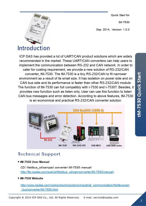
Quick Start fortM-7530Sep 2014, Version 1.0.0ICP DAS has provided a lot of UART/CAN product solutions which are widely recommended in the market. These UART/CAN converters can help users to implement the communication between RS-232 and CAN network. In order to cater for costing requirement, we provide a new solution of RS-232/CAN converter, tM-7530. The tM-7530 is a tiny RS-232/CAN to fit narrower environment as a result of its small size. It has isolation on power side and on CAN bus side and its performance is faster than other RS-232/CAN module. provides new function such as listen only. User can use this function to listen CAN bus messages and error detection. According to above features, tM-7530is an economical and practical RS-232/CAN converter solution.tM-7530 User ManualCD:\ fieldbus_cd\can\pac\ converter\ tM-7530\ manual\/pub/cd/fieldbus_cd/can/converter/tM-7530/manual\ tM-7530 Website/root/product/solutions/industrial_communication/fieldbus/cantM-7530 Utility/pub/cd/fieldbus_cd/can/converter/tM-7530/utilityICP DAS Website/1 -----------------------------------------------------------------------------------Hardware Introduction and InstallationThe left graph is the surface of tM-7530. It uses D-sub9 pin female connector as RS-232 communicationinterface and uses 2 or 3 wire to connect CAN buswith spring type connector. It has 2 LED indicatorsRun and Err. They are used to response modulestatus immediately at all time.Table: RS-232 Pin Assignment Table: Power and CAN Bus Pin AssignmentHow to connect with spring type connector? Press and Insert.2-----------------------------------------------------Configuration/Run ModeThere is a dip-switch on the bottom of tM-7530. After switching and rebooting, the tM-7530 will enter into Normal mode or Init mode.3-----------------------------------------------------tM-7530 wire connection4--------------------------------------Terminal Resistor5------------------------------------------------------------Software Utility IntroductionThere is no terminator resistor in the tM-7530. Therefore, if users would like to use terminator resistor, it is necessary to wire a 120Ω resistance on the CAN bus, as following figure.The tM-7530 uses VxCAN Utility to configure module and test. The VxCAN Utility is based on the Virtual CAN technology which is developed by the ICP DAS and is used to integrate the CAN interfaces of the different CAN converters from the ICP DAS. All of the CAN interfaces found by the PC will be sequentially mapping to the virtual CAN ports by the Virtual CAN driver. Users just use the virtual CAN ports to develop their application, and don ’t need to know what kind of6----------------------------------------------------------------------------Configure tM-7530 via VxCAN UtiliyBefore powering on the CAN converters, users must set them to the Init mode. Users need to switch the Init/Normal DIP-Switch to Init positionStep 3: Click the buttonThe configuration is divided to three areas with different color. They are UART, Communication, and CAN configuration area. Each area can set different parameters of tM-7530.After finishing the configuration, users can click the button “Save All Setting” to save the configuration in to the EEPROM of the CAN converter. If users would like to recover the parameters to the factory default, click “Load Default Setting” button to recover all of the configuration parameters to be default value. Afterwards, users can use the button “Save All Settings”to save the default parameters in to the EEPROM of the CAN converter.The default values of the parameters of the CAN converter are shown below.RS-232:RS-232 Baud rate = 115200Data Bit = 8Stop Bit = 1Parity = NoneAdd Checksum = NoError Response = NoTimeStamp Response = NoCAN:CAN Specification = 2.0ACAN bus Baud rate = 125KAcceptance Code = 000Acceptance Mask = 000Communication:7----------------------------------------------------------------Test tM-7530 via VxCAN UtiliySet the Init/Normal DIP switch of the CAN converter to normal mode. When the CAN module runs on the normal mode, the run LED indicator will be turned on. If the CAN converter sends or receives the CAN messages, the run LED will flash once per message.Step 3: Click the search buttonCheck the “Active Port ” and Click “Confirm ” button to enable the CAN port of the CAN converter. The parameters set here are not stored in the EEPROM. If users would like to configure the other parameters expect the CAN parameters, please use Configuration interface of the VxCAN Utility to do that.buttonThe test interface is divided to two areas. One is for sending CAN messages, and the other is for reception. If users want to send CAN message, fill the data into the corresponding field, and click “Send ” button. If the CAN converter gets any CAN messages, they will be shown in received area automatically. About the details for the VxCAN Utility operation please refer to the users ’ manual of the VxCAN Utility in the following web site.。
丝印7530芯片参数

丝印7530芯片参数1.引言1.1 概述概述:丝印7530芯片是一款具有重要意义的微型电子芯片,具有多种独特的特性和功能。
本文旨在全面介绍丝印7530芯片的参数,并探讨其在不同领域的应用前景。
丝印7530芯片是一款先进的电子元器件,具有较高的性能和可靠性。
其参数设计经过精密计算和测试,能够满足多种应用的需求。
这款芯片采用了先进的丝印技术制造,具有极高的精度和稳定性。
同时,丝印7530芯片还具备较低的功耗和较高的工作效率,能够满足长时间稳定运行的要求。
丝印7530芯片的主要特性包括但不限于以下几点:首先,该芯片具有较高的集成度和处理能力,能够同时实现多种任务。
其次,丝印7530芯片的存储容量较大,能够满足大规模数据存储和处理的需求。
此外,该芯片还具备较高的抗干扰性和稳定性,能够在各种恶劣环境下正常工作。
丝印7530芯片在电子领域有着广泛的应用前景。
它可以应用于智能手机、笔记本电脑、平板电脑等消费类电子产品中,提供强大的处理能力和高效的数据处理能力。
同时,该芯片也可以应用于工业自动化、交通运输、医疗设备等领域,提供可靠的控制和监测能力。
总之,丝印7530芯片作为一款先进的微型电子芯片,具有多种独特的特性和功能。
通过深入了解其参数和应用前景,可以更好地理解和应用这款芯片,进一步推动电子技术的发展和创新。
1.2 文章结构文章结构包括引言、正文和结论三部分。
引言部分主要对丝印7530芯片的背景和重要性进行简要介绍,概述本篇文章的内容,并说明文章的结构和目的。
具体内容包括以下几方面:1. 引言开始可以对丝印7530芯片进行简要介绍,说明其作用和应用范围,突出其重要性和市场需求。
2. 接着,对本篇文章的结构进行概述,说明正文中将分别介绍芯片参数概述和丝印7530芯片的主要特性,以及结论部分总结芯片参数和展望其应用前景。
3. 最后,明确本篇文章的目的,可以是为了让读者了解丝印7530芯片的参数,以及了解其在未来的应用前景,为相关领域的研究和实践提供参考。
sp325snw说明书

SP 325SNw/377SNwX (M288/M0BC)Parts CatalogU001 EXTERIOR U002ARDF/SCANNERU003OPERATIONU004LASER UNITU005 PAPER FEED U006PCUU007TRANSFER/SEPARATIONU008FUSINGU009 PAPER EXIT U010DUPLEXU011MAIN DRIVEU012ELECTRICALMAIN FRAMEU001 EXTERIOR10.M1561240 EXTENSION TRAY: MF:ASS'Y 7.G0521518SPRING - LOCK LEVER3.04513006N(x6)TAPPING SCREW -3X61.04503008N(x2)TAPPING SCREW -M3X88.M1341382RAIL:SCANNER:OPEN AND CLOSE15.M1561392GUIDE PLATE:SCANNER:OPEN ANDCLOSE14.M1561272COIL SPRING:SCANNER6.AG070514 MAGNET CATCH 9.M1341386 RAIL:STOPPER:SC ANNER:OPEN AND CLOSE19.M2891252 BUTTON 12.M1561254 SHAFT:TURN:SCA NNER:LEFT17.M2882632 DECAL:PICK-UP P APER JAM 5.11050761 CLAMP:LWS-0511A18.M2891251 COVER:FRONT20.M2891253COVER:SIDE PLATE:LEFT4.04513008N 2.04503012N 13.M1561256 11.M1561250 16.M2871370(x4) (x4) SHAFT:TURN:SCA COVER:UPPER:MF COVER:REAR LOTAPPING SCREW - TAPPING SCREW: NNER:RIGHT P WERM3X8 3X12U001 Array EXTERIOR21.M2891255COVER:SIDE PLATE:RIGHT22.M2891259COVER:REAR MIDDLE:3IN1ARDF/SCANNER1.M2881600SCANNER:ASS'Y2.NoteSee 2D parts catalog for the components of the ARDF.OPERATION2.M2881402(x2)(EU/AA/NA):OPERATION PANEL:3IN1:ASS'Y3.M2881404 (CHN):OPERATION PANEL:3IN1:ASS'Y 1.04503010N (x 3) TAPPING SCREW - M3X10SER UNIT U004_S001M2871851OPTICAL WRITING UNIT:ASS'YU004LASER UNIT6.04543008Q(x3)TAPPING SCREW:3X8U004_S001OPTICAL WRITING UNIT:ASS'Y3.04513006NTAPPING SCREW -3X64.04523010NBINDING SELF-TAPPING SCREW:3X101.04503008N(x6)TAPPING SCREW -M3X8 2.04503012N(x2)TAPPING SCREW:3X125.04543006Q (x 2)TAPPING SCREW - M3X67.M2871851OPTICAL WRITINGUNIT:ASS'YU005.PAPER FEED U005_S001M2872505PAPER TRAY:ASS'Y4.04523010N BINDING SELF-TA PPING SCREW:3X 105.08050104(x7)RETAINING RINGS -E:SILENCER:DIA4 6.A1532117ROLLER TERMINAL25.M0122668SHAFT:PAPER FEED:ASS'Y10.G0123050SIDE FENCE GEAR12.G0292767BY-PASS FEED COVER27.M0122701ROLLER:INTERFACE:DRIVE28.M0122702ROLLER:INTERFACE:DRIVEN29.M0122705(x2)SPRING:ROLLER7.AA143520SHOULDER SCREW - M33.04513006N (x 3)TAPPING SCREW - 3X624.M0122631 CLOTH:EARTH:PA PER FEED 1.04503008N (x2)TAPPING SCREW - M3X89.D1272514(x3) ELECTROMAGNET IC CLUTCH:3.5T:M ANUAL FEED 8.AW020198 (x3) PHOTOINTERRUP TOR:LG2A14NL13.04513006N (x5)TAPPING SCREW -3X626.M0122673RAIL:PAPER TRAY:RIGHT13.G1022717COVER:DC SOLENOID17.GF013001BOTTOM PLATE PAD15.G1272627PAPER FEED ROLLER - MM3211.G0201160(x2)SNAP RING14.G1022789STOPPER:PHOTOINTERRUPTOR39.M0122742 GROUND PLATE:D RIVEN:REGISTRAT ION ROLLER38.M0122741 GROUND PLATE:D RIVE:REGISTRATI ON ROLLER 30.M0122711BUSHING:REGISTRATION:DRIVEN:LEFT41.M0122744 (x2)GUIDE:REGISTRATION48.M0122833DECAL:SIDE FENCE:MANUAL FEED31.M0122715GUIDE PLATE:TRANSPORT:UPPER32.M0122718REGISTRATION ROLLER:DRIVE33.M0122719REGISTRATION ROLLER:DRIVEN34.M0122722 (x2)SPRING:ROLLER:REGISTRATION47.M0122830 MECHANICAL SPRI NG CLUTCH:MANU AL FEED 37.M0122730 BUSHING:REGIST RATION:DRIVEN:RI GHT36.M0122725 SPRING:FEELER:R EGISTRATION 43.M0122753 (x2) BUSHING:ROLLER: DRIVEN49.M0122859 GUIDE PLATE:UPP ER:MANUAL FEED42.M0122745GROUND PLATE:DRIVEN45.M0122816FRICTION PAD:HOLDER:MANUAL FEED:ASS'Y35.M0122723FEELER:REGISTRATION:SENSOR44.M0122806SHEET:GUIDE:MANUAL FEED SUB-UNIT46.M0122824FEELER:MANUALFEED40.M0122743DECAL:GUIDE PLATE:TRANSPORT:UPPER65.M1542815 DECAL:FEED PAP ER AGAIN:PREVEN TION 85.M2872876SIDE FENCE:MANUAL FEED:LEFT67.M1542879EXTENSION TRAY:MANUAL FEED84.M2872875SIDE FENCE:MANUAL FEED:RIGHT86.M2872878(x2)RACK:MANUAL FEED58.M1162672RAIL:PAPER TRAY:LEFT66.M1542831 DC SOLENOID:9.6 W:24V 87.M2872879 (x2) COMPRESSION SP RING:SIDE FENCE: MANUAL FEED83.M2872871 COVER:MANUAL F EED TABLE 82.M2872671 FEELER:PAPER E ND SENSOR88.M2872881 BASE:MANUAL FE ED TABLE53.M0124488(x6)BUSHING:DIA6XDIA10X650.M0122860PAPER FEED ROLLER:MANUAL FEED51.M0122874COMPRESSION SPRING:MANUAL FEED64.M1542805GUIDE PLATE:MANUAL FEED:LOWER52.M0122880COMPRESSION SPRING:SEPARATION54.M0752610 (x4) COMPRESSION SP RING:LOCK:SIDE F ENCE 56.M1092589LEVER:LOCK:SIDEFENCE57.M1092592PAWL:LOCK:SIDEFENCE23.M0122613COMPRESSION SPRING:SEPARATION18.M0122590COIL SPRING:EARTHPAPER TRAY:ASS'Y62.M1542640 COVER:PAPER TR AY:LEFT59.M1542616 LEVER:PAPER VO LUME SENSOR 69.M2872589 PAPER TRAY:REA R70.M2872611TRAY:BASE60.M1542618DECAL:PAPER TRAY:FRONT2.04504008NTAPPING SCREW -M4X821.M0122605FRICTION PAD:ADHESION16.GA063084COMPRESSION SPRING:AUXILIARY:SIDE FENCE61.M1542629COVER:PAPER TRAY:MIDDLE55.M1092584PRESSURE PLATE:SIDE FENCE:LEFT17.GF013001BOTTOM PLATE PAD22.M0122612COMPRESSION SPRING:TRAY BOTTOM PLATE20.M0122604SPRING:RELEASE:TRAY BOTTOM PLATE63.M1542641COVER:PAPER TRAY:RIGHT19.M0122603STOPPER:BASE PLATE73.M2872618 COVER:SIDE FENC E:LEFT 72.M2872615SIDE FENCE:LEFT79.M2872626DECAL:EXTENSION TRAY78.M2872625LEVER:LOCK:EXTENSION TRAYPAPER TRAY:ASS'Y77.M2872624 (x2)CLICK:SIDE FENC E81.M2872636 GEAR:16Z80.M2872627LEVER:LOCK:ENDFENCE71.M2872612END FENCE76.M2872623PAWL:LOCK:END FENCE74.M2872620SIDE FENCE:RIGHT75.M2872622COVER:SIDE FENCE:RIGHTPCU2.04523010N(x2)BINDING SELF-TAPPING SCREW:3X101.04503008N (x2)TAPPING SCREW - M3X8 1.04503008N (x 4) TAPPING SCREW - M3X8TRANSFER/SEPARATION7.M1016259 ELECTRODE PLAT E:SEPARATION 5.M0126260COVER:ELECTRODE PLATE6.M1016250TRANSFER ROLLER4.M0126256 ROLLER:POSITION ING:TRANSFER R OLLER3.M0126255GEAR:TRANSFERROLLER1.M0126252(x2)BUSHING:TRANSFER ROLLER:RIGHT 2.M0126254 (x2)SPRING:TRANSFER ROLLERU008.FUSINGU008_S001M2874031(EU/AA):FUSING UNIT:ASS'Y U008_S002M2874033(CHN):FUSING UNIT:ASS'YU008_S003M2874030(NA):FUSING UNIT:ASS'YU008 FUSING4.04513008N (x2)TAPPING SCREW - M3X846.M0124699DECAL:WARNING ( HIGHTEMPERATU RE):FRONT2.04503010N (x2)TAPPING SCREW - M3X1035.M0124270 (x2)THERMAL INSULA TING BUSHING:FU SING UNITU008_S001(EU/AA):FUSING UNIT:ASS'Y12.AW110116 THERMOSTAT 8.08046127(x4)HEXAGONAL BOLT:DOUBLE SCREW:M3X821.M0124204LEVER:LEFT:FRAME:FUSING7.08025318(x4)BINDING HEAD TAPPING SCREW:ES:3X10¹⁹.M0124186COVER:LEFT UPPER:ASS'Y48.M2874031(EU/AA):FUSING UNIT:ASS'Y9.09543010N SCREW:POLISHED ROUND/SPRING:M 3X10¹⁰.AA143520 (x7)SHOULDER SCRE W - M3 3.04513006N (x2)TAPPING SCREW -3X614.M0124053GEAR:HOT ROLLER1.03603006N(x11)SCREW - M3X615.M0124055(x2)RADIAL BALL BEARING:35X47X713.G1274328DECAL - HIGH TEMPERATURE5.04533006N(x6)TAPPING SCREW -M3X620.M0124202 (x2)LEVER:PRESSURE6.07200040E(x2)RETAINING RING -M418.M0124135FEELER:PAPER FEED SENSOR16.M0124109SPRING:FEELER:EXIT11.AW020198PHOTOINTERRUPTOR:LG2A14NL14.04513008N(x4)TAPPING SCREW -M3X817.M0124120(x3)TENSION SPRING:PICKOFF PAWLU008_S001(EU/AA):FUSING UNIT:ASS'Y41.M0124287 COVER:RIGHT UP PER:FUSING 38.M0124281(x2)RETAINING RINGS-C:HOT ROLLER39.M0124284LEVER:PRESSURE:LEFT25.M0124212FUSING ENTRANCE GUIDE PLATE:UPPER42.M0124292FUSING COVER:UPPER48.M2874031(EU/AA):FUSING UNIT:ASS'Y22.M0124205 LEVER:RIGHT:FRA ME:FUSING31.M0124223 THERMAL INSULA TING BUSHING:HO T ROLLER 36.M0124276 COVER:LEFT:LOW ER:FUSING23.M0124208(x3)BRACKET:GATE PAWL24.M0124211PLATE NUT:HEATER40.M0124285LEVER:PRESSURE:RIGHT34.M0124266COVER:RIGHT LOWER:FUSING32.M0124229(x2)TENSION SPRING:FUSING:PRESSURE26.M0124213 (x2)BUSHING:PRESSURE ROLLER28.M0124216(x2)TENSION SPRING:FUSING:GUIDE PLATE29.M0124217FUSING ENTRANCE GUIDE PLATE:LOWER37.M0124279CLEANING ROLLER:ASS'Y30.M0124220HOT ROLLER33.M0124253PRESSURE ROLLER:DIA3027.M0124215GUIDE PLATE:EXITU008_S001(EU/AA):FUSING UNIT:ASS'Y54.M2874263 THERMISTOR 52.M2874221(EU/AA/CHN):HEATER:700W:220V:INFRARED53.M2874234HOUSING:THERMOSTAT:ASS'Y48.M2874031(EU/AA):FUSING UNIT:ASS'Y44.M0124295 GROUND PLATE:A SS'Y50.M2874206(x3)STRIPPER PAWLS43.M0124293(x4)EXIT ROLLER:EXIT:FUSING45.M0124603DECAL:GUIDE PLATE:B12.AW110116 THERMOSTAT 21.M0124204LEVER:LEFT:FRAME:FUSING17.M0124120(x3)TENSION SPRING:PICKOFF PAWL7.08025318(x4)BINDING HEAD TAPPING SCREW:ES:3X10¹⁹.M0124186COVER:LEFT UPPER:ASS'Y49.M2874033(CHN):FUSING UNIT:ASS'Y8.08046127(x4) HEXAGONAL BOLT :DOUBLE SCREW: M3X8 3.04513006N (x2)TAPPING SCREW -3X69.09543010N SCREW:POLISHED ROUND/SPRING:M 3X10 14.M0124053 GEAR:HOT ROLLE R10.AA143520 (x7) SHOULDER SCRE W - M3 15.M0124055 (x2)RADIAL BALL BEA RING:35X47X71.03603006N (x11)SCREW - M3X6 5.04533006N (x6)TAPPING SCREW - M3X613.G1274328 DECAL - HIGH TEM PERATURE6.07200040E(x2)RETAINING RING -M418.M0124135FEELER:PAPER FEED SENSOR16.M0124109SPRING:FEELER:EXIT11.AW020198PHOTOINTERRUPTOR:LG2A14NL14.04513008N(x4)TAPPING SCREW -M3X820.M0124202 (x2)LEVER:PRESSURE41.M0124287 COVER:RIGHT UP PER:FUSING 38.M0124281(x2)RETAINING RINGS-C:HOT ROLLER39.M0124284LEVER:PRESSURE:LEFT25.M0124212FUSING ENTRANCE GUIDE PLATE:UPPER42.M0124292FUSING COVER:UPPER49.M2874033(CHN):FUSING UNIT:ASS'Y22.M0124205 LEVER:RIGHT:FRA ME:FUSING31.M0124223 THERMAL INSULA TING BUSHING:HO T ROLLER 36.M0124276 COVER:LEFT:LOW ER:FUSING23.M0124208(x3)BRACKET:GATE PAWL24.M0124211PLATE NUT:HEATER40.M0124285LEVER:PRESSURE:RIGHT34.M0124266COVER:RIGHT LOWER:FUSING32.M0124229(x2)TENSION SPRING:FUSING:PRESSURE26.M0124213 (x2)BUSHING:PRESSURE ROLLER28.M0124216(x2)TENSION SPRING:FUSING:GUIDE PLATE29.M0124217FUSING ENTRANCE GUIDE PLATE:LOWER37.M0124279CLEANING ROLLER:ASS'Y30.M0124220HOT ROLLER33.M0124253PRESSURE ROLLER:DIA3027.M0124215GUIDE PLATE:EXITU008_S002(CHN):FUSING UNIT:ASS'Y54.M2874263 THERMISTOR 52.M2874221(EU/AA/CHN):HEATER:700W:220V:INFRARED53.M2874234HOUSING:THERMOSTAT:ASS'Y49.M2874033(CHN):FUSING UNIT:ASS'Y44.M0124295 GROUND PLATE:A SS'Y50.M2874206(x3)STRIPPER PAWLS43.M0124293(x4)EXIT ROLLER:EXIT:FUSING45.M0124603DECAL:GUIDE PLATE:B12.AW110116 THERMOSTAT 21.M0124204LEVER:LEFT:FRAME:FUSING17.M0124120(x3)TENSION SPRING:PICKOFF PAWL7.08025318(x4)BINDING HEAD TAPPING SCREW:ES:3X10¹⁹.M0124186COVER:LEFT UPPER:ASS'Y47.M2874030(NA):FUSING UNIT:ASS'Y8.08046127(x4) HEXAGONAL BOLT :DOUBLE SCREW: M3X8 3.04513006N (x2)TAPPING SCREW -3X69.09543010N SCREW:POLISHED ROUND/SPRING:M 3X10 14.M0124053 GEAR:HOT ROLLE R10.AA143520 (x7) SHOULDER SCRE W - M3 15.M0124055 (x2)RADIAL BALL BEA RING:35X47X71.03603006N (x11)SCREW - M3X6 5.04533006N (x6)TAPPING SCREW - M3X613.G1274328 DECAL - HIGH TEM PERATURE6.07200040E(x2)RETAINING RING -M418.M0124135FEELER:PAPER FEED SENSOR16.M0124109SPRING:FEELER:EXIT11.AW020198PHOTOINTERRUPTOR:LG2A14NL14.04513008N(x4)TAPPING SCREW -M3X820.M0124202 (x2)LEVER:PRESSURE41.M0124287 COVER:RIGHT UP PER:FUSING 38.M0124281(x2)RETAINING RINGS-C:HOT ROLLER39.M0124284LEVER:PRESSURE:LEFT25.M0124212FUSING ENTRANCE GUIDE PLATE:UPPER42.M0124292FUSING COVER:UPPER47.M2874030(NA):FUSING UNIT:ASS'Y22.M0124205 LEVER:RIGHT:FRA ME:FUSING31.M0124223 THERMAL INSULA TING BUSHING:HO T ROLLER 36.M0124276 COVER:LEFT:LOW ER:FUSING23.M0124208(x3)BRACKET:GATE PAWL24.M0124211PLATE NUT:HEATER40.M0124285LEVER:PRESSURE:RIGHT34.M0124266COVER:RIGHT LOWER:FUSING32.M0124229(x2)TENSION SPRING:FUSING:PRESSURE26.M0124213 (x2)BUSHING:PRESSURE ROLLER28.M0124216(x2)TENSION SPRING:FUSING:GUIDE PLATE29.M0124217FUSING ENTRANCE GUIDE PLATE:LOWER37.M0124279CLEANING ROLLER:ASS'Y30.M0124220HOT ROLLER33.M0124253PRESSURE ROLLER:DIA3027.M0124215GUIDE PLATE:EXITU008_S003(NA):FUSING UNIT:ASS'Y54.M2874263 THERMISTOR 51.M2874220(NA)F HEATER:700W:120V:INFRARED53.M2874234HOUSING:THERMOSTAT:ASS'Y47.M2874030(NA):FUSING UNIT:ASS'Y44.M0124295 GROUND PLATE:A SS'Y50.M2874206(x3)STRIPPER PAWLS43.M0124293(x4)EXIT ROLLER:EXIT:FUSING45.M0124603DECAL:GUIDE PLATE:B7.M0134455 GEAR:DRIVE:EXIT ROLLER1.04503008N (x2)TAPPING SCREW - M3X89.M1544499GROUND PLATE:EXIT ROLLER3.M0124453(x4)EXIT ROLLER4.M0124454(x4)SPRING:EXIT ROLLER:EXIT5.M0124458DISCHARGE BRUSH:EXIT:ASS'Y DRAWINGU009PAPER EXIT2.07200040E 6.M0124488 8.M0134470(x2)RETAINING RING - (x2)BUSHING:DIA6XDIEXIT ROLLER:DUPLEXM4 A10X63.04533006N (x2)TAPPING SCREW - M3X6 4.04543006Q(x4)TAPPING SCREW -M3X610.M0134610GEAR:DRIVE:DUPLEX6.08050104(x7)RETAINING RINGS-E:SILENCER:DIA411.M0134611BRACKET:DRIVE:DUPLEX:ASS'Y18.M0134664GUIDE PLATE:VERTICAL TRANSPORT:UPPER8.AW020198PHOTOINTERRUPTOR:LG2A14NL116.M0134661 STOPPER:TRANSP ORT SUB-UNIT:DU PLEX 17.M0134663 GUIDE PLATE:VER TICAL TRANSPOR T:LOWER20.M0134667 SPRING:COVER:S WITCHBACK:OPEN AND CLOSE 13.M0134623 (x2) SPRING:EXIT19.M0134666 SHAFT:COVER:SW ITCHBACK:OPEN A ND CLOSE 5.07200040E (x2)RETAINING RING - M42.04503010N (x2)TAPPING SCREW - M3X1012.M0134622(x4)EXIT ROLLER:DUPLEX9.M0124488 (x4)BUSHING:DIA6XDIA10X61.04503008N(x4)TAPPING SCREW -M3X815.M0134635SPRING:OPEN AND CLOSE:RIGHT7.08050106RETAINING RINGS-E:SILENCER:DIA614.M0134624 (x2)SPRING:EXIT:NO.224.M0134672 SHEET:HORIZONT AL TRANSPORT:RI GHT 22.M0134669(x2)MAGNET CATCH:ASS'Y40.M0134794DECAL:GUIDE PLATE:VERTICAL TRANSPORT:UPPER34.M0134761TRANSPORT ROLLER:DUPLEX:MIDDLE27.M0134684SHEET:DUPLEX23.M0134671SHEET:HORIZONTAL TRANSPORT:LEFT37.M0134771TIMING BELT:HORIZONTAL TRANSPORT29.M0134688 GROUND PLATE:H ORIZONTAL TRAN SPORT:REAR 21.M0134668 SHEET:GUIDE:HO RIZONTAL TRANS PORT:LOWER36.M0134765 (x3) PULLEY:TRANSPO RT 39.M0134785 SPRING:COVER:S WITCHBACK:OPEN AND CLOSE38.M0134772 TIMING BELT:DRIV E 32.M0134697 LEVER:OPEN AND CLOSE:RIGHT30.M0134691 LEVER:OPEN AND CLOSE:LOWER28.M0134685BUTTON:OPEN AND CLOSE:LOWER25.M0134673LEVER:OPEN ANDCLOSE:NO.126.M0134674LEVER:OPEN ANDCLOSE:NO.231.M0134696LEVER:OPEN ANDCLOSE:LEFT35.M0134762TRANSPORT ROLLER:DUPLEX:EXIT33.M0134698BRACKET:OPEN AND CLOSE:LOWER46.M2874719 (x2)PIN:GUIDE:TRANS PORT 43.M1540265STEPPER MOTOR42.M1174662COVER:SWITCHBACK:OPEN AND CLOSE41.M0134797FEELER:SENSOR:VERTICAL TRANSPORT47.M2874895(x4)PIN:GUIDE:UPPER44.M1544694GUIDE:HORIZONTAL TRANSPORT:UPPER45.M1544695GUIDE:HORIZONTAL TRANSPORT:LOWERU011MAIN DRIVE7.11050758 CLAMP:LWSM-030 6A 11.M0121120GEAR:DRIVE:FUSING:NO.313.M0121128GEAR:DRIVE:FUSING:NO.43.07200040ERETAINING RING -M42.04543006QTAPPING SCREW -M3X68.G0521120 SPRING - PAPER E XIT RELEASE 5.11050197 WIRE SADDLE4.08050104(x6)RETAINING RINGS -E:SILENCER:DIA4 1.04513006N (x10)TAPPING SCREW - 3X610.M0121119 GEAR:DRIVE:FUSI NG:NO.2 12.M0121123 GEAR:DRIVE:PAPE R FEED:NO.39.M0121117 GEAR:DRIVE:DRU M 16.M0121172 GEAR:DRIVE:MAN UAL FEED SECTIO N:NO.217.M0131178 BRACKET:DRIVE:D UPLEX15.M0121171GEAR:DRIVE:MANUAL FEED SECTION:NO.114.M0121150BRUSHLESS MOTOR:DC 36.7W18.M1161118GEAR:DRIVE:FUSING:NO.119.M1161121GEAR:DRIVE:PAPER FEED:NO.120.M1161122GEAR:DRIVE:PAPER FEED:NO.26.11050568CLAMP:LWSS-0504U011MAIN DRIVE22.M1171136 GEAR:DRIVE:DUPL EX SECTION 23.M1541177CASE:DRIVE:ASS'Y21.M1161124GEAR:DRIVE:PAPER FEED:NO.4U012 ELECTRICAL1.04513006N (x4)TAPPING SCREW -3X6 5.M2875001PCB:WIFI9.M2885052PCB:ECBCTL:3IN1:ASS'Y2.04543006Q(x4)TAPPING SCREW -M3X63.16072774FERRITE CORE:K3FF4.M1545402 POWER PACK:ASS 'Y7.M2875312(EU/AA):POWER SUPPLY UNIT:ASS'Y6.M2875311(CHN):POWER SUPPLY UNIT:ASS'Y 8.M2875313(NA):POWER SUPPLY UNIT:ASS'YU013MAIN FRAME2.04513006N 17.M0121037 18.M0121040 6.04543014Q 13.12042612(x21)TAPPING SCREW - TONER BOTTLE:CASECASE:DISCHARGELAMPTAPPING SCREW:3X14(x2)MICRO SWITCH:D33X6 V-16506-3C253.04513014N TAPPING SCREW: 3X14 11.11050760 (x8)CLAMP:LWSM-0511A10.11050758CLAMP:LWSM-0306A16.GW010007 PHOTO REFLECTI ON SENSOR:EXIT 5.04543006Q (x5)TAPPING SCREW - M3X68.11050568 CLAMP:LWSS-0504 14.AX640199 FAN:MM80:25MM:D C 2.16W1.04503008N (x12)TAPPING SCREW -M3X8 4.04513030N (x2)TAPPING SCREW: 3X3010.11050758 (x7) CLAMP:LWSM-030 6A7.09504006NSCREW - M4X6 12.11050762 15.G0271180 20.M0121065 19.M0121063 9.11050598(x2) (x2) CASE:TERMINAL (x4) CLAMP:LWSS-1NCLAMP:LWS-0711A RUBBER FOOT - G TERMINAL:CHARGF EU013MAIN FRAME32.M2881089 CASE:USB 24.M0121097 (x3)SUPPORTER:PAPER:TRANSPORT25.M0124120(x3)TENSION SPRING:PICKOFF PAWL26.M0124601DECAL:LEVER:ENVELOPE:LEFT28.M0BB1100(EU/AA):(M0BC):HEAT INSULATING PLATE:FUSING:FRONT23.M0121089 (x3) GUIDE:PAPER:LEA DING EDGE 29.M1541099 (M288):HEAT INSU LATING PLATE:FU SING:FRONT:TYPE A30.M1542056 DISCHARGE LAMP27.M0124602DECAL:LEVER:ENVELOPE:RIGHT 31.M2871043COVER:U CONVEYER BELT:DUPLEX22.M0121088COIL SPRING:RAIL:RIGHT21.M0121066 (x4)SPRING:TERMINAL:CHARGEACCESSORIES1.M0BC04312.M10113013.M10157994.M15456975.M15456996.M2880431(EU/AA):(M0BC):MODEL NAME PLAT PLATE:LOGO:RIC (CHN):POWER SUPPLY CORD (NA):POWER SUPPLY CORD:125V:10 (EU/AA):POWER SUPPLY CORD:250 (M288):MODEL NAME PLATE:SP325S E:SP325SNW:EXTRA A V:10A NW03603006N04503008N04503010N04503012N04504008N04513006N04513008NSCREW - M3X6TAPPING SCREW - M3X8TAPPING SCREW - M3X10TAPPING SCREW:3X12TAPPING SCREW - M4X8TAPPING SCREW - 3X6TAPPING SCREW - M3X804513014N04513030N04523010N04533006N04543006Q04543008Q04543014QTAPPING SCREW:3X14TAPPING SCREW:3X30BINDING SELF-TAPPING SC REW:3X10TAPPING SCREW - M3X6TAPPING SCREW - M3X6TAPPING SCREW:3X8TAPPING SCREW:3X1407200040ERETAINING RING - M408025318BINDING HEAD TAPPING SC REW:ES:3X10 08046127 HEXAGONAL BOLT:DOUBLE SCREW:M3X8 08050104RETAINING RINGS-E:SILENC ER:DIA4 08050106 RETAINING RINGS-E:SILENC ER:DIA609504006N SCREW - M4X609543010NSCREW:POLISHED ROUND/SPRING:M3X1011050197110505681105059811050758110507601105076111050762WIRE SADDLECLAMP:LWSS-0504CLAMP:LWSS-1NCLAMP:LWSM-0306ACLAMP:LWSM-0511ACLAMP:LWS-0511ACLAMP:LWS-0711A12042612MICRO SWITCH:D3V-16506-3 C25 16072774FERRITE CORE:K3 FF。
(总结452类)753E753ES753D说明书
射频网络分析仪★频率范围:或★带有固态转换的集成化参数测试装置★达的动态范围★快的测量速度和数据传递速率★大屏幕显示器加上供外部监视器用的输出★同时显示所有个参数★将仪器状态和数据存储调用到内置软盘驱动器★可选用的时域测量和扫描谐波测量射频网络分析仪为满足研制实验室或生产制造的测试需求,在速度、性能和方便使用上提供了无与伦比的结合。
以其覆盖或频率范围的集成化参数测试装置、达的动态范围以及频率扫描和功率扫描,为表征有源或无源网络、元器件和子系统的线性和非线性特性提供了圆满的解决技术指导文件。
所使用的新型微处理器使测量和数据传递速率比以往的型号快达倍之多。
网络分析仪的特点是有个独立的测量通道,可同时测量和显示所有个参数。
可以选择用幅度、相位、群延迟、史密斯圆图、极坐标、驻波比或时域格式来显示反射和传输参数的任意组合。
便于使用的专用功能键能迅速访问各个测量功能。
可以利用达个刻度格子在高分辩率的彩色显示器上以重叠或分离屏面的形式来观察测量结果。
为了驱动更大的外部监视器,以便于观察,增加了与兼容的输出。
较好的通用性和性能一个集成化的合成源提供了达的输出功率(用选件可达),的频率分辩率和线性频率,对数频率,列表频率,和功率扫描功能。
三个调谐接收机可以在(带有选件频率扩展)处或(标准)的宽动态范围内进行独立的功率测量或同时比值测量。
集成化的测试装置可以在不使用倍频器的情况下,测量达装置的传输和反射特性。
为了在非同轴系统中进行方便而精确的测量,特提供了**校准。
利用内置适配器移去校准技术,还能实现对非插入式器件的高精度测量。
高稳定度的频率基准(选件)提高了对高器件,如表面声波()器件、晶体谐振器或介质谐振滤波器的频率测量精度。
为了提高配置的灵活性,选件取消了内置测试装置,以便能选择自己所需的测试装置。
选件可与和参数测试装置以及供其它特殊应用的专用测试装置配套使用。
用于自动生产的新型选件可以删除内部显示和降低仪器成本(选件)。
MAX-线号机LM-370A--LM-380A键盘按键功能说明书
MAX-线号机LM-370A--LM-380A 键盘按键功能说明书MAX 线号机LM-370A/LM-380A键盘按键功能说明书日本MAX公司LM-380A新一代微电脑线号印字机:是针对电力成套及其他需要布线行业制作套管、标签标示的专业设备。
本公司本着“品质优良、价格合理、服务及时”的经营原则。
并不断追求更高的企业品质以回馈各界的支持与厚爱!公司所有产品均为终身维护,一年免费保修。
LM-380A微电脑高速套管打印机一套标准配置机器一台,手提箱一个,专用电源一个,LM-IR310B色带一盘,LM-IR300B色带卡匣1个.中英文说明书各一本.LM-380A微电脑高速套管打印机主要功能:MAX LETATWIN LM-380A电脑线号印字机是针对专业人士制作套管及标签标示所全新设计(中文化的标示,操作更简单轻松)1、高速打印:LM-380A拥有快速的打印功能,可提供每秒25m的打印速度,能够在一分钟内高速打印出35个20mm长的套管。
2、最大打印长度:LM-380A一次最大打印套管长度可达20M(LM-370A为6M)、标签贴纸一次最大打印长度可达5M(LM-370A为1M)3、LM-380A拥有强大的内存容量:内建大容量记忆体,最大可容纳40000个字元。
4、功能强大的PC专用软件:LM-380A可以使用附赠的专用软件编辑,搭配CF CARD储存大量的标示文字资料,操作更能让您随心所欲。
5、切刀深度调整:LM-380A拥有独特的切刀调整功能,当半切刀位置太深或太浅时,可以通过调整半切深度拉杆来调整切刀深度。
6、全中文输入,中文化键盘及界面(除了英文字母、数字和特殊符号,中文字也可以利用键盘直接拼音输入。
7、高质量打印材料:可打印0.5mm、1.0mm、1.5mm、2.0mm、2.5mm、4.0mm、6.0mm的套管和热收缩套管,打印速度快,不掉色。
还可打印5mm、9mm、12mm不干胶标签.LM-380A高速电脑套管打号机(线号印字机,线号机,印字机)是配线行业的一次飞跃,高性能、300dpi的打印精度,清晰、永不褪色。
