分水岭算法——MATLAB
分水岭算法(完整版)

青 衣
11053413 李小泷
• 分水岭算法实现步骤:先把图片转化为灰度梯度级图像, 在图像梯度空间内逐渐增加一个灰度阈值,每当它大于一 个局部极大值时,就把当时的二值图像(只区分陆地和水 域,即大于灰度阈值和小于灰度阈值两部分)与前一个时 刻(即灰度阈值上一个值的时刻)的二值图像进行逻辑异或 (XOR)操作,从而确定出灰度局部极大值的位置 。根据所 有灰度局部极大值的位置集合就可确定分水岭。
Lrgb = label2rgb(L, 'jet', 'w', 'shuffle');%转 化为伪彩色图像 subplot(122); imshow(Lrgb)%显示伪彩色图 像 title('分水岭伪彩色图像') 青 衣
figure; imshow(I), hold on himage = imshow(Lrgb);%在原图上显示 伪彩色图像 set(himage, 'AlphaData', 0.3); title('原图像上的Lrgb处理')
imcomplement(Iobr));%形态学重建 Iobrcbr = imcomplement(Iobrcbr);%图像求反 subplot(122); imshow(Iobrcbr), %显示重建求反后的 图像 title('重建求反后的图像(Iobrcbr)')
fgm = imregionalmax(Iobrcbr);%局部极大值 figure; imshow(fgm), %显示重建后局部极大值图像 title('重建后局部极大值图像(fgm)')
此时再进行分水岭变换并显示得到的效果。
分水岭算法的概念及原理
分水岭算法的概念及原理
分水岭算法(Watershed Algorithm)是一种用于图像分割的算法,它基于山脊线(ridge line)和水流的概念,能够将图像中的物体分割出来。
该算法的主要原理是将图像看作地形地貌,将亮度视作高程,通过模拟洪水灌溉的过程,将图像分割成多个区域。
分水岭算法的核心思想是:将图像中的亮度极值点视作各个地块的山峰,从这些山峰出发,模拟水流的分布过程,即从高处向低处流动,在流动的过程中形成不同的流域。
当水流面临两个流域的交汇区时,就会形成分水岭,从而将图像分割成多个区域。
具体的分水岭算法步骤如下:
1.预处理:将彩色图像转换成灰度图像,并进行平滑处理,以减少噪声的干扰。
2.计算梯度图像:通过计算图像灰度值的梯度来得到梯度图像。
梯度较大的地方通常表示物体的边界。
3.标记种子点:选取梯度图像中的极值点作为种子点(山峰),这些点将成为分水岭的起点。
4.洪水灌溉:从种子点开始模拟水流的分布过程。
初始化一个标记图像,将种子点周围标记为相应的流域。
然后将水从种子点开始向相邻的像素流动,直到遇到另一个流域或已经被标记过。
这样不断地灌溉,最终得到一个水流分布图。
6.后处理:将不可靠的区域(通常是细长的、过于小的区域)进行合并,得到最终的分割结果。
总的来说,分水岭算法是一种基于洪水灌溉模拟的图像分割算法,通过模拟水流的分布过程,将图像分割成多个区域,从而准确地分割出物体边界。
分水岭算法之自下而上的模拟泛洪的算法流程
分水岭算法是一种用于图像分割的算法,它能够将图像中的不同区域进行分割,并找到它们之间的分界线。
此算法的主要思路是通过模拟泛洪的方式来不断扩展各个区域,直到它们彼此分离为止。
分水岭算法通常分为两种实现方式,一种是自上而下的方式,另一种是自下而上的方式。
本文将重点介绍和探讨自下而上的模拟泛洪的分水岭算法流程,以帮助读者更好地理解该算法的原理和实现方法。
一、初始化1. 为图像创建距离变换图:首先需要将输入的图像进行预处理,创建一个距离变换图。
距离变换图中的每个像素表示该像素到最近的边界像素的距离。
2. 初始化标记图:标记图用来记录每个像素的标记信息,标记哪些像素属于同一个区域。
初始化时,将标记图中的像素值都设为0。
3. 初始化队列:为了模拟泛洪的过程,需要使用一个队列来存储待处理的像素。
将图像中的所有边界像素加入到队列中。
二、泛洪过程1. 从队列中取出一个像素,并记录其标记值。
2. 遍历该像素周围的像素,如果周围的像素未被标记过且不是边界像素,则将其加入到队列中,并将其标记值设为与当前像素相同。
3. 如果周围的像素已被标记过,且标记值不同于当前像素,则说明这两个区域相遇了。
此时需要将它们之间的分界线更新为分水岭,并将其加入到分水岭集合中。
4. 重复以上步骤,直到队列为空。
三、分水岭线处理1. 对分水岭集合中的像素进行排序:根据它们到最近的边界像素的距离,对分水岭集合中的像素进行排序。
2. 将排序后的像素逐个取出,遍历其周围的像素:如果周围的像素属于相同的区域,则将其标记为该区域的像素。
3. 重复以上步骤,直到所有分水岭像素都被处理完毕。
四、结果展示1. 根据标记图,可以将图像进行分割并展示不同区域的边界线或分水岭线。
2. 可以对图像进行进一步的后处理,如去除噪声、优化分割结果等。
通过以上的介绍,相信读者对于自下而上的模拟泛洪的分水岭算法流程有了更深入的了解。
虽然分水岭算法在图像分割领域具有广泛的应用,但其实现过程相对复杂,需要深入理解其原理和算法流程。
分水岭分割算法matlab
分水岭分割算法matlab分水岭分割算法是一种常用的图像分割算法,用于将图像中不同的物体或区域进行分割。
在MATLAB中,可以使用图像处理工具箱中的函数来实现分水岭分割算法。
下面是一种基本的MATLAB代码示例,演示了如何使用分水岭分割算法对图像进行分割:matlab.% 读取图像。
image = imread('image.jpg');% 将图像转换为灰度图像。
grayImage = rgb2gray(image);% 对灰度图像进行预处理,例如滤波或增强等。
% 计算图像的梯度。
gradientImage = imgradient(grayImage);% 使用分水岭算法进行图像分割。
segmented = watershed(gradientImage);% 将分割结果可视化。
figure;imshow(label2rgb(segmented));% 可以选择性地将不同的分割区域标记出来。
hold on;boundaries = imdilate(segmented == 0, ones(1)); imshow(boundaries, 'Color', 'red');% 添加标题和标签。
title('分水岭分割结果');上述代码中,首先读取了一张图像,并将其转换为灰度图像。
然后对灰度图像进行预处理,例如滤波或增强等操作。
接下来,计算图像的梯度,这将有助于找到图像中的边缘和区域边界。
最后,使用`watershed`函数进行图像分割,并将分割结果可视化。
需要注意的是,分水岭分割算法对图像的预处理和参数选择非常重要,可以根据具体的应用场景进行调整和优化。
此外,MATLAB 还提供了其他图像分割算法和工具函数,可以根据实际需求选择合适的方法进行图像分割。
希望以上内容能够对你理解分水岭分割算法在MATLAB中的应用有所帮助。
如有更多问题,请随时提问。
matlab图像处理教程1
基本概念一点通从理论上讲,图像是一种二维的连续函数,然而在计算机上对图像进行数字处理的时候,首先必须对其在空间和亮度上进行数字化,这就是图像的采样和量化的过程。
空间坐标(x,y)的数字化称为图像采样,而幅值数字化称为灰度级量化。
对一幅图像采样时,若每行(横向)采样数为M,每列(纵向)采样数为N,则图像大小为M*N个像素,f(x,y)表示点(x,y) 处的灰度值,则F(x,y)构成一个M*N 实数矩阵****************************经验分享:“像素”的英文为“pixel”,它是“picture”和“element”的合成词,表示图像元素的意思。
我们可以对“像素”进行如下理解:像素是一个面积概念,是构成数字图像的最小单位。
****************************把采样后所得的各像素灰度值从模拟量到离散量的转换称为图像灰度的量化。
量化是对图像幅度坐标的离散化,它决定了图像的幅度分辨率。
量化的方法包括:分层量化、均匀量化和非均匀量化。
分层量化是把每一个离散样本的连续灰度值只分成有限多的层次;均匀量化是把原图像灰度层次从最暗至最亮均匀分为有限个层次,如果采用不均匀分层就称为非均匀量化。
当图像的采样点数一定时,采用不同量化级数的图像质量不一样。
量化级数越多,图像质量越好;量化级数越少,图像质量越差。
量化级数小的极端情况就是二值图像。
****************************经验分享:“灰度”可以认为是图像色彩亮度的深浅。
图像所能够展现的灰度级越多,也就意味着图像可以表现更强的色彩层次。
如果把黑——灰——白连续变化的灰度值量化为256个灰度级,灰度值的范围为0~255,表示亮度从深到浅,对应图像中的颜色为从黑到白。
****************************因此,对数字图像进行处理,也就是对特定的矩阵进行处理。
在C语言中,对M×N数字图像处理的核心代码如下:for (j=1;j<N+1;j++)for(i=1;i<M+1;i++){对I(i,j)的具体运算};在Matlab中,对M×N数字图像处理的核心代码如下:for i=1:Nfor j=1:M对I(i,j)的具体运算endend一幅数字图像可以用一个矩阵来表示,对数字图像进行处理,实质上就是对特定的图像矩阵进行变换的过程,因此,图像变换是数字图像处理技术的基础。
自然水系(或分水岭)自动提取的matlab实现方案
水系提取算法(D8)的matlab 实现D8算法是当今非常成熟的提取水系(或分水岭)的计算机实现方法。
这里笔者结合自身的编程实践介绍D8算法的matlab 实现过程,谨与大家分享。
D8算法分为两部分实现:每个栅格点水流方向的计算;每个栅格点汇水面积的计算。
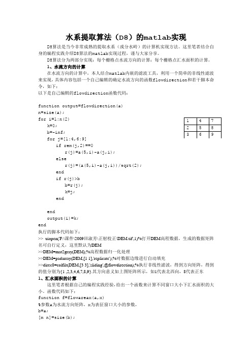
1、水流方向的计算在水流方向的计算中,本人结合matlab 内嵌的滤波工具,利用一个简单的非线性滤波来实现,具体内容包括一个自己编辑的确定水流方向的函数flowdirection 和若干脚本命令,如下:以下是自己编辑的flowdirection 函数代码:function output=flowdirection(a)n=size(a);for i=1:n(2) k=0; b=-inf; for j=[1:4,6:9]if rem(j,2)==0r(j)=a(5,i)-a(j,i);elser(j)=(a(5,i)-a(j,i))/sqrt(2);endif r(j)>bb=r(j);k=j;endendoutput(i)=k;end执行的脚本代码如下:>> uiopen('F:\课件\2009田淑芳\正射校正\DEM.tif',1)%打开DEM 高程数据,生成的数据矩阵名可自行定义,这里默认为DEM>>DEM=mat2gray(DEM);%高程数据归一化处理>>DEM=padarray(DEM,[1 1],'replicate');%对数据边缘进行自动填充>>direc8=colfilt(DEM,[3 3],'sliding',@flowdirection);%执行非线性滤波,得到方向矩阵,得到的值分别为{1 ,2,3,4,6,7,8,9}.其方向意义如上图矩阵所示,如1代表北西向,8代表正东1、汇水面积的计算这里笔者根据自己的编程实践经验,给出一个函数来计算不同窗口大小下汇水面积的大小。
matlab 分割三维模型算法

matlab 分割三维模型算法一、引言三维模型分割是计算机视觉领域的一个重要问题,它在三维建模、物体识别、医学图像分析等领域都有广泛的应用。
在matlab中,有多种方法可以实现三维模型分割,其中最常见的是基于图像分割算法和深度学习算法。
本文将主要介绍基于图像分割算法的matlab三维模型分割方法。
二、matlab三维模型分割算法1. 基于区域生长的三维模型分割算法区域生长是一种基于相似度测量的图像分割技术,它可以将相邻像素点合并成为一个区域。
在三维模型中,区域生长可以被用来将同一部位的点聚合成为一个整体。
具体实现步骤如下:(1)选取种子点:首先需要选取一个或多个种子点作为起始点。
(2)定义相似度测量标准:根据实际情况定义相似度测量标准。
(3)寻找邻居:以种子点为中心,在周围搜索与之相似的点。
(4)加入到当前区域:如果找到了符合条件的点,则将其加入到当前区域中。
(5)重复上述步骤:不断重复上述步骤,直到不能再添加新的点为止。
2. 基于分水岭算法的三维模型分割算法分水岭算法是一种基于图像梯度的分割技术,它可以将图像中的每个像素点标记为前景或背景。
在三维模型中,分水岭算法可以被用来将不同部位的点分离开来。
具体实现步骤如下:(1)计算梯度:首先需要计算出三维模型中每个像素点的梯度值。
(2)标记种子点:根据需要进行标记,例如将某些像素点标记为前景或背景。
(3)生成高斯金字塔:为了减少计算量,需要对三维模型进行高斯金字塔处理。
(4)生成距离变换图:根据梯度值和种子点位置生成距离变换图。
(5)应用分水岭算法:根据距离变换图应用分水岭算法进行分割。
3. 基于聚类的三维模型分割算法聚类是一种基于相似性度量的数据分类方法,它可以将数据集中相似的数据归为一类。
在三维模型中,聚类可以被用来将同一部位的点聚合成为一个整体。
具体实现步骤如下:(1)选取特征:首先需要选取合适的特征来描述三维模型中的点。
(2)定义相似度测量标准:根据实际情况定义相似度测量标准。
分水岭算法综述
分水岭算法综述分水岭算法是图像分割领域中常用的一种算法,它可以将图像分割成不同的区域,每个区域内的像素具有相似的特征。
本文将对分水岭算法进行综述,介绍其原理、应用以及优缺点。
一、分水岭算法的原理分水岭算法的原理源于水在山谷中流动的过程。
首先,将图像看作一个地形图,较亮的区域对应山峰,较暗的区域对应山谷。
然后,通过在地形图上进行洪水填充,使得水从山峰的高处流向山谷的低处,最终形成水汇聚的区域。
这些水汇聚的区域即为图像的分割结果。
分水岭算法的核心是确定图像中的山峰和山谷。
为了实现这一点,需要进行图像的预处理。
首先,对图像进行灰度化处理,将彩色图像转换为灰度图像。
然后,通过应用梯度算子,计算图像中每个像素的梯度值。
梯度值较大的像素被认为是山峰,梯度值较小的像素被认为是山谷。
在预处理完成后,可以开始进行分水岭算法的主要步骤。
首先,将山峰像素标记为前景,山谷像素标记为背景。
然后,将标记的像素区域称为markers。
接下来,通过对markers进行洪水填充,将水从山峰处逐渐流向山谷。
当水汇聚到一定程度时,会形成分割的边界,即分水岭。
二、分水岭算法的应用分水岭算法在图像分割领域有广泛的应用。
以下是一些常见的应用场景:1. 医学图像分割:分水岭算法可以用于医学图像的分割,如MRI图像中的肿瘤分割、X射线图像中的骨骼分割等。
通过将图像分割成不同的区域,医生可以更好地观察和分析病变部位。
2. 地质勘探:分水岭算法可以用于地质勘探中的岩石分割。
通过将地质图像分割成不同的区域,可以更好地识别和分析不同类型的岩石,有助于矿产资源的开发和利用。
3. 视觉检测:分水岭算法可以用于视觉检测中的目标分割。
通过将图像中的目标分割出来,可以更好地进行目标识别和跟踪,有助于自动驾驶、智能监控等领域的发展。
三、分水岭算法的优缺点分水岭算法具有以下优点:1. 算法简单:分水岭算法的原理简单易懂,实现相对容易。
2. 适用性广泛:分水岭算法可以用于不同类型的图像,包括医学图像、地质图像、自然图像等。
分水岭分割算法及其基本步骤
分水岭分割算法及其基本步骤
宝子,今天咱来唠唠分水岭分割算法哈。
分水岭分割算法呢,就像是在一幅图像的“地形”上找分界线。
想象一下图像的灰度值就像地形的高度,灰度高的地方像山峰,灰度低的地方像山谷。
这个算法的目标呀,就是找到那些把不同“区域”分开的“分水岭”。
比如说一幅有多个物体的图像,它能把每个物体所在的区域分开来。
那它的基本步骤大概是这样滴。
先得把图像看成是一个拓扑地貌。
这就好比把图像变成了一个有山有谷的小世界。
然后呢,要确定一些“种子点”,这些种子点就像是每个区域的起始点。
比如说,你想把图像里的一个圆形物体和周围分开,就在圆形物体内部选个点当种子点。
接着呀,从这些种子点开始,像水从源头往外流一样,根据图像的灰度信息往外扩展。
灰度变化平缓的地方就容易被包含进来,而灰度变化突然的地方,就像是遇到了悬崖或者堤坝,就成了可能的分界线。
在这个过程中呢,算法会不断判断哪些区域该合并,哪些该分开。
就像你在整理东西,把同类的放在一起,不同类的分开。
最后呢,就形成了分割后的各个区域啦。
这个算法可有趣了,就像是在图像的小世界里当一个规划师,给每个物体或者区域划分地盘呢。
不过它也有小缺点哦,有时候可能会对噪声比较敏感,就像你在一个有点乱的地方划分区域,那些小干扰就可能让划分不那么准确啦。
但总体来说,在图像分割领域,分水岭分割算法还是很厉害的一个小能手哦。
。
分水岭算法程序实现过程详解
注 意 : 第 一 轮,把标 记点的 邻居点 放入相 应的优 先级队 列后,先 进先出 的原则 处理队 列中的 像素结 点,找 到一个 非零结 点后,执 行第1,2,3步 ,执 行完第 3步之 后,重新 更新队 列再次 进行扫 描.
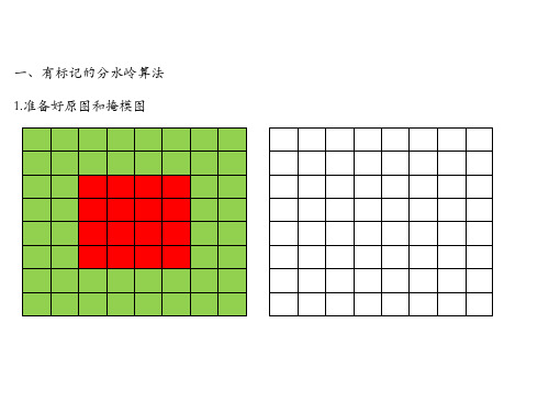
一、有标记的分水岭算法 1.准备好原图和掩模图
2.对掩模图做初始化标记,以形成最初的注水区域,设置mask边框值为-1,即每个标记 种子,全为正值,1,2,3...都是一个初始聚水盆,标记的周围一圈的邻居像素就是聚 像素四邻域内有标记点,并将邻居像素对应原图 中的点放入相应的优先级队列
优先级队列
Y
0 1 2 3 4 5 6
...
254 255
X
4.递归注水过程,通过扫描0-255高度值队列,从队列0开始,如果找到一个像素结点,则弹出 该结点,并退出扫描.
①如果该点在mask中的四邻域,只存在一个非0值,则将该点标记为该非0值. ②如果存在两 个不同的非0值,表示该点为两个注水盆地的边缘,即分水岭线,在mark图像中标记该点为-1. ③扫描该点的邻居点,是否存在为0的mark域,存在的话这把该邻域点按照rgb高度值,放入
二、传统分水岭算法
传统的分水岭分割方法,其基本思想是把图像看作是测地学上的拓扑地貌,图 像中每一像素的灰度值表示该点的海拔高度,每一个局部极小值及其影响区 域称为集水盆地,而集水盆地的边界则形成分水岭.基于梯度图像的直接分水 岭算法容易导致图像的过分割,产生这一现象的原因主要是由于输入的图像 存在噪声等而产生许多小的集水盆地,从而导致分割后的图像不能将图像中 有意义的区域表示出来.所以必须对分割结果的相似区域进行合并.
下标L表示左,R表示右,T表示上,B表示下,abs表示取绝对值
分水岭算法源代码及其分析和注释

/*====================================================================函数名: Watershed功能:用标记-分水岭算法对输入图像进行分割算法实现:无输入参数说明: OriginalImage --输入图像(灰度图,0~255)SeedImage --标记图像(二值图,0-非标记,1-标记)LabelImage --输出图像(1-第一个分割区域,2-第二个分割区域,...)row --图像行数col --图像列数返回值说明:无====================================================================*/void WINAPI CDib::Watershed(unsigned char **OriginalImage, char** SeedImage, int **LabelImage, int row, int col){// using namespace std;//标记区域标识号,从1开始int Num=0;int i,j;//保存每个队列种子个数的数组vector<int*> SeedCounts;//临时种子队列queue<POINT> quetem;//保存所有标记区域种子队列的数组,里面放的是种子队列的指针vector<queue<POINT>*> vque;int* array;//指向种子队列的指针queue<POINT> *pque;POINT temp;for(i=0;i<row;i++){for(j=0;j<col;j++)LabelImage[i][j]=0;}int m,n,k=0;BOOL up,down,right,left,upleft,upright,downleft,downright;//8 directions...//预处理,提取区分每个标记区域,并初始化每个标记的种子队列//种子是指标记区域边缘的点,他们可以在水位上升时向外淹没(或者说生长)//pan's words:我的理解是梯度值较小的象素点,或者是极小灰度值的点。
分水岭算法的概念及原理
分水岭算法Watershed Algorithm(分水岭算法),顾名思义,就是根据分水岭的构成来考虑图像的分割。
现实中人们可以或者说可以想象有山有湖的景象,那么那一定是水绕山,山围水的情形。
当然在需要的时候,要人工构筑分水岭,以防集水盆之间的互相穿透。
而区分高山(plateaus)与水的界线,以及湖与湖之间的间隔或都是连通的关系,就是分水岭(watershed)。
为了得到一个相对集中的集水盆,那么让水涨到接近周围最高的山顶就可以了,这样的话,我们就可以用来获取边界灰阶大,中间灰阶小的物体区域了,它就是集水盆。
分水岭算法的概念及原理分水岭分割方法,是一种基于拓扑理论的数学形态学的分割方法,其基本思想是把图像看作是测地学上的拓扑地貌,图像中每一点像素的灰度值表示该点的海拔高度,每一个局部极小值及其影响区域称为集水盆,而集水盆的边界则形成分水岭。
分水岭的概念和形成可以通过模拟浸入过程来说明。
在每一个局部极小值表面,刺穿一个小孔,然后把整个模型慢慢浸入水中,随着浸入的加深,每一个局部极小值的影响域慢慢向外扩展,在两个集水盆汇合处构筑大坝,即形成分水岭。
分水岭的计算过程是一个迭代标注过程。
分水岭比较经典的计算方法是L. Vincent提出的。
在该算法中,分水岭计算分两个步骤,一个是排序过程,一个是淹没过程。
首先对每个像素的灰度级进行从低到高排序,然后在从低到高实现淹没过程中,对每一个局部极小值在h阶高度的影响域采用先进先出(FIFO)结构进行判断及标注。
分水岭变换得到的是输入图像的集水盆图像,集水盆之间的边界点,即为分水岭。
显然,分水岭表示的是输入图像极大值点。
因此,为得到图像的边缘信息,通常把梯度图像作为输入图像,即g(x,y)=grad(f(x,y))={[f(x,y)-f(x-1,y)]2[f(x,y)-f(x,y-1)]2}0.5式中,f(x,y)表示原始图像,grad{.}表示梯度运算。
分水岭算法对微弱边缘具有良好的响应,图像中的噪声、物体表面细微的灰度变化,都会产生过度分割的现象。
分水岭算法的详细介绍(附c代码)转

分水岭算法的详细介绍(附c代码)转所谓分水岭算法有好多种实现算法,拓扑学,形态学,浸水模拟和降水模拟等方式。
要搞懂就不容易了。
Watershed Algorithm(分水岭算法),顾名思义,就是根据分水岭的构成来考虑图像的分割。
现实中我们可以或者说可以想象有山有湖的景象,那么那一定是水绕山,山围水的情形。
当然在需要的时候,要人工构筑分水岭,以防集水盆之间的互相穿透。
而区分高山(plateaus)与水的界线,以及湖与湖之间的间隔或都是连通的关系,就是我们可爱的分水岭(watershed)。
为了得到一个相对集中的集水盆,那么让水涨到都接近周围的最高的山顶就可以了,再涨就要漏水到邻居了,而邻居,嘿嘿,水质不同诶,会混淆自我的。
那么这样的话,我们就可以用来获取边界灰阶大,中间灰阶小的物体区域了,它就是集水盆。
浸水法,就是先通过一个适当小的阈值得到起点,即集水盆的底;然后是向周围淹没也就是浸水的过程,直到得到分水岭。
当然如果我们要一直淹没到山顶,即是一直处理到图像灰阶最高片,那么,当中就会出现筑坝的情况,不同的集水盆在这里想相遇了,我们要洁身自爱,到这里为止,因为都碰到边界了;那么即使在相遇时没有碰到最高灰阶的地方,也需要人工构筑分水岭,区分不同的区域。
不再上山。
构筑属于自己的分水岭在计算机图形学中,可利用灰度表征地貌高。
图像中我们可以利用灰度高与地貌高的相似性来研究图像的灰度在空间上的变化。
这是空域分析,比如还可以通过各种形式的梯度计算以得到算法的输入,进行浸水处理。
分水岭具有很强的边缘检测能力,对微弱的边缘也有较好的效果。
这与分水岭扩张的阈值的设置有关系,阈值可以决定集水盆扩张的范围。
但自我构筑的能力却不受影响。
为会么这么说呢?为什么有很强的边缘检测能力,而又能得到相对集中的连通的集水盆?现实中很好办,我们在往凹地加水的时候,直到它涨到这一块紧凑的山岭边缘就不加了;但是如果有一条小山沟存在,那没办法,在初始阈值分割的时候,也就是山沟与集水盆有同样的极小值,而且它们之间是以这个高度一直连接的。
标记分水岭割算法(Matlab)
标记分水岭分割算法(Matlab)Separating touching objects in an image is one of the more difficult image processing operations. The watershed transform is often applied to this problem. The watershed transform finds "catchment basins"(集水盆) and "watershed ridge lines"(山脊线) in an image by treating it as a surface where light pixels are high anddark pixels are low.Segmentation using the watershed transform works better if you can identify, or "mark," foreground objects and background locations. Marker-controlled watershed segmentation follows this basic procedure:1. Compute a segmentation function. This is an image whose dark regions are theobjects you are trying to segment.2. Compute foreground markers. These are connected blobs of pixels within each ofthe objects.3. Compute background markers. These are pixels that are not part of any object.4. Modify the segmentation function so that it only has minima at the foregroundand background marker locations.5. Compute the watershed transform of the modified segmentation function.Use by Matlab Image Processing ToolboxStep 1: Read in the Color Image and Convert it to Grayscalergb = imread('pears.png');I = rgb2gray(rgb);imshow(I)text(732,501,'Image courtesy of Corel',...'FontSize',7,'HorizontalAlignment','right')Step 2: Use the Gradient Magnitude as the Segmentation FunctionUse the Sobel edge masks, imfilter, and some simple arithmetic to compute the gradient magnitude. The gradient is high at the borders of the objects and low(mostly) inside the objects.hy = fspecial('sobel');hx = hy';Iy = imfilter(double(I), hy, 'replicate');Ix = imfilter(double(I), hx, 'replicate');gradmag = sqrt(Ix.^2 + Iy.^2);figure, imshow(gradmag,[]), title('Gradient magnitude (gradmag)') Can you segment the image by using the watershed transform directly on thegradient magnitude?L = watershed(gradmag);Lrgb = label2rgb(L);figure, imshow(Lrgb), title('Watershed transform of gradient magnitude (Lrgb)')No. Without additional preprocessing such as the marker computations below, usingthe watershed transform directly often results in"oversegmentation."Step 3: Mark the Foreground ObjectsA variety of procedures could be applied here to find the foreground markers, which must be connected blobs of pixels inside each of the foreground objects. In this example you'll use morphological techniques called "opening-by-reconstruction"and "closing-by-reconstruction" to "clean" up the image. These operations will create flat maxima inside each object that can be located using imregionalmax(指定灰度值局部极大区域).开运算和闭运算:先腐蚀后膨胀称为开;先膨胀后腐蚀称为闭。
matlab中分水岭算法的原理

matlab中分水岭算法的原理English:The watershed algorithm is a segmentation technique that is used to separate touching or overlapping objects in an image. It is based on the concept of a topographic surface, where the pixel intensities are interpreted as the elevation of the surface. The algorithm begins by identifying the regional minima in the image, which are considered as the markers for the different objects. Then, the algorithm simulates a flooding process, where the elevated regions (or catchment basins) are gradually filled with water until they merge at the regional minima. This process creates a set of boundaries that separate the different catchment basins, resulting in the segmentation of the image. The watershed algorithm is particularly useful for segmenting complex and irregular objects, as it is able to find boundaries based on both intensity and spatial information.Translated content:分水岭算法是一种用于分割图像中接触或重叠对象的分割技术。
自然水系(或分水岭)自动提取的matlab实现方案

水系提取算法(D8)的matlab 实现D8算法是当今非常成熟的提取水系(或分水岭)的计算机实现方法。
这里笔者结合自身的编程实践介绍D8算法的matlab 实现过程,谨与大家分享。
D8算法分为两部分实现:每个栅格点水流方向的计算;每个栅格点汇水面积的计算。
1、水流方向的计算在水流方向的计算中,本人结合matlab 内嵌的滤波工具,利用一个简单的非线性滤波来实现,具体内容包括一个自己编辑的确定水流方向的函数flowdirection 和若干脚本命令,如下:以下是自己编辑的flowdirection 函数代码:function output=flowdirection(a)n=size(a);for i=1:n(2) k=0; b=-inf; for j=[1:4,6:9]if rem(j,2)==0r(j)=a(5,i)-a(j,i);elser(j)=(a(5,i)-a(j,i))/sqrt(2);endif r(j)>bb=r(j);k=j;endendoutput(i)=k;end执行的脚本代码如下:>> uiopen('F:\课件\2009田淑芳\正射校正\DEM.tif',1)%打开DEM 高程数据,生成的数据矩阵名可自行定义,这里默认为DEM>>DEM=mat2gray(DEM);%高程数据归一化处理>>DEM=padarray(DEM,[1 1],'replicate');%对数据边缘进行自动填充>>direc8=colfilt(DEM,[3 3],'sliding',@flowdirection);%执行非线性滤波,得到方向矩阵,得到的值分别为{1 ,2,3,4,6,7,8,9}.其方向意义如上图矩阵所示,如1代表北西向,8代表正东1、汇水面积的计算这里笔者根据自己的编程实践经验,给出一个函数来计算不同窗口大小下汇水面积的大小。
分水岭算法3_watershed

在matlab中正确的使用水坝算法分割图像网址:/pro/html/201312/8297.html上看到一篇讲解这个算法的帖子,看看如何能够正确的使用这个算法。
例如,这是一张图像,我们希望用watershed的方法对这幅图像进行分割。
当然,在matlab里面,直接对这幅图像使用watershed这个函数,并不能得到很好的分割结果。
这里我们看看如何能够正确的使用watershed分割这个图像,同时也看看watershed 变换和watershed分割的区别。
首先,我们直接调用watershed,看看结果是什么样的view sourceprint?1.url = '/wp-content/uploads/auto_save_image/2013/12/004306JQI.p ng';2.bw = imread(url);3.L = watershed(bw);4.Lrgb = label2rgb(L);5.imshow(Lrgb)刚刚看到结果的时候,我们可能很纳闷分割结果为什么是这个样子。
让我们用imfuse这个函数,将两幅图像显示在一起,将图像中的一个区块放大看imshow(imfuse(bw,Lrgb))axis([10 175 15 155])我们可以看出,watershed变换总会在每一个局部最小的地方给出一个水坝区域。
这些小的黑色“点”就是局部最小值,因此在每个周围都有一个watershed区域。
即使我们填补了这些空洞,我们也没法获得用户想要的分割效果。
这就是我们要注意到的watershed变换和watershed分割的区别。
也就是说,watershed分割算法是watershed变换的一种应用,而简单的对图像进行watershed变换,并不能达到最终的分割目的。
这里有一个帖子The Watershed Transform: Strategies for Image Segmentation,详细介绍了watershed变换的原理。
分水岭算法MATLAB
% 分水岭算法clear, close all;clc;PathName='t ';%t为自填内容,下面p类似FileName=[PathName 'p'];Image=imread(FileName);subplot(2,2,1);subimage(Image);title('原图');;pixval on;B=[1,1,1;1,1,1;1,1,1];%方形结构元E8=[-1,0;-1,1;0,1;1,1;1,0;1,-1;0,-1;-1,-1]; % 8-连通结构元坐标maskLenth=length(E8); % 结构元点的个数[X,Y]=size(Image);%原始图像image 赋值给A1n=1;A(:,:,n)=Image;M=zeros(X,Y);Mark_Image=zeros(X,Y);%产生距离图while sum(sum(A(:,:,n)))~=0A(:,:,n+1)= imerode(A(:,:,n),B);U(:,:,n)= (A(:,:,n)-A(:,:,n+1))*n;M=M+U(:,:,n);n=n+1;endn=n-1;subplot(2,2,2);imagesc(M,[0,n]);title('距离图');% 搜寻局部最大值,将其放入Deal_ImageDeal_Image=zeros(X,Y);while n>0for high=1:Xfor width=1:Y%********************************************************************Mark_Bool=0;if M(high,width)==n%______________________________________________________________ for dot=1:maskLenthi=E8(dot,1); j=E8(dot,2);if high+i>=1 & width+j>=1 & high+i<=X & width+j<=Y & M(high+i,width+j)>M(high,width);Mark_Bool=1;break;end % if_endend % for dot_end%______________________________________________________________ if Mark_Bool==0;Deal_Image(high,width)=M(high,width);end %if end%______________________________________________________________ end %if end%********************************************************************end %for-endend %for-endn=n-1;end % while n=0 endDeal_Image =[Deal_Image>=1]subplot(2,2,3);subimage(Deal_Image);title('输出图像');Mark_Number=1;while n>0for high=1:Xfor width=1:YMark_Bool=0;%********************************************************************if M(high,width)==n%______________________________________________________________for dot=1:maskLenthi=E8(dot,1); j=E8(dot,2);if high+i>=1 & width+j>=1 & high+i<=X & width+j<=Y & Mark_Image(high+i,width+j)>0;Mark_Image(high,width)=Mark_Image(high+i,width+j);Mark_Bool=1;break;end % if_endend % for dot_end%______________________________________________________________if Mark_Bool==0;Mark_Image(high,width)=Mark_Number;Mark_Number=Mark_Number+1;end %if end%______________________________________________________________pause;subplot(2,2,2);imagesc(Mark_Image,[0,Mark_Number]);title('输出图像');end %if end%********************************************************************end %for-endend %for-endn=n-1;end % while n=0 endsubplot(2,2,3);imagesc(Mark_Image,[0,Mark_Number]);title('分割后的图像');uicontrol('Style','edit','string',['分割出区域:',Num2str(Mark_Number-1),'个'],...'Position', [400 0 150 18],'FontSize',12,'FontWeight','light');。
- 1、下载文档前请自行甄别文档内容的完整性,平台不提供额外的编辑、内容补充、找答案等附加服务。
- 2、"仅部分预览"的文档,不可在线预览部分如存在完整性等问题,可反馈申请退款(可完整预览的文档不适用该条件!)。
- 3、如文档侵犯您的权益,请联系客服反馈,我们会尽快为您处理(人工客服工作时间:9:00-18:30)。
% 有多种方法可以应用在这里来获得前景标记,这些标记必须是前景对象内部的连接斑点像素。这个例子中,将使用形态学技术“基于开的重建”和“基于闭的重建”来清理图像。
% 接下来,通过腐蚀后重建来做基于开的重建计算。
Ie = imerode(I, se);
Iobr = imreconstruct(Ie, I);
figure('units', 'normalized', 'position', [0 0 1 1]);
subplot(1, 2, 1); imshow(I, []); title('灰度图像');
% 使用MATLAB图像处理工具箱
% 注:期间用到了很多图像处理工具箱的函数,例如fspecial、imfilter、watershed、label2rgb、imopen、
% imclose、imreconstruct、imcomplement、imregionalmax、bwareaopen、graythresh和imimposemin函数等。
% The gradient is high at the borders of the objects and low (mostly) inside the objects.
% 使用Sobel边缘算子对图像进行水平和垂直方向的滤波,然后求取模值,sobel算子滤波后的图像在边界处会显示比较大的值,在没有边界处的值会很小。
figure('units', 'normalized', 'position', [0 0 1 1]);
subplot(1, 2, 1); imshow(gradmag,[]), title('梯度幅值图像')
subplot(1, 2, 2); imshow(Lrgb); title('梯度幅值做分水岭变换')
% Step 2: Use the Gradient Magnitude as the Segmentation Function
% 第2步:将梯度幅值作为分割函数
% Use the Sobel edge masks, imfilter, and some simple arithmetic to compute the gradient magnitude.
% 开操作后,接着进行闭操作,可以移除较暗的斑点和枝干标记。对比常规的形态学闭操作和基于闭的重建操作。首先,使用imclose:
Ioc = imclose(Io, se);
Ic = imclose(I, se);
figure('units', 'normalized', 'position', [0 0 1 1]);
% No. Without additional preprocessing such as the marker computations below, using the watershed transform directly often results in "oversegmentation."
subplot(1, 2, 1); imshow(I, []); title('灰度图像');
subplot(1, 2, 2); imshow(Io), title('图像开操作')
% Next compute the opening-by-reconstruction using imerode and imreconstruct.
% 现在使用imdilate,然后使用imreconstruct。注意必须对输入图像求补,对imreconstruct输出图像求补。
% IM2 = imcomplement(IM)计算图像IM的补集。IM可以是二值图像,或者RGB图像。IM2与IM有着相同的数据类型和大小。
Iobrd = imdilate(Iobr, se);
Iobrcbr = imreconstruct(imcomplement(Iobrd), imcomplement(Iobr));
Iobrcbr = imcomplement(Iobrcbr);
figure('units', 'normalized', 'position', [0 0 1 1]);
% 4.修改分割函数,使其仅在前景和后景标记位置有极小值。
% 5. Compute the watershed transform of the modified segmentation function.
% 5.对修改后的分割函数做分水岭变换计算。
% Use by Matlab Image Processing Toolbox
% Can you segment the image by using the watershed transform directly on the gradient magnitude?
% 可否直接对梯度幅值图像使用分水岭算法?
L = watershed(gradmag);
Lrgb = label2rgb(L);
% 开操作是腐蚀后膨胀,基于开的重建(基于重建的开操作)是腐蚀后进行形态学重建。下面比较这两种方式。首先,用imopen做开操作。
se = strel('disk', 20);
Io = imopen(I, se);
figure('units', 'normalized', 'position', [0 0 1 1]);
% 这些操作将会在每个对象内部创建单位极大值,使得可以使用imregionalmax来定位。
% 开运算和闭运算:先腐蚀后膨胀称为开;先膨胀后腐蚀称为闭。开和闭这两种运算可以除去比结构元素小的特定图像细节,同时保证不产生全局几何失真。
% 开运算可以把比结构元素小的突刺滤掉,切断细长搭接而起到分离作用;闭运算可以把比结构元素小的缺口或孔填充上,搭接短的间隔而起到连接作用。
% 直接使用梯度模值图像进行分水岭算法得到的结果往往会存在过度分割的现象。因此通常需要分别对前景对象和背景对象进行标记,以获得更好的分割效果。
% Step 3: Mark the Foreground Objects
% 第3步:标记前景对象
% A variety of procedures could be applied here to find the foreground markers,
% Step 1: Read in the Color Image and Convert it to Grayscale
% 第一步:读入彩色图像,将其转化成灰度图像
clc; clear all; close all;
rgb = imread('pears.png');
if ndims(rgb) == 3
% which must be connected blobs of pixels inside each of the foreground objects.
% In this example you'll use morphological techniques called "opening-by-reconstruction" and "closing-by-reconstruction" to "clean" up the image.
% 1. Compute a segmentation function. This is an image whose dark regions are the objects you are trying to segment.
% 1.计算分割函数。图像中较暗的区域是要分割的对象。
% 2. Compute foreground markers. These are connected blobs of pixels within each of the objects.
hy = fspecial('sobel');
hx = பைடு நூலகம்y';
Iy = imfilter(double(I), hy, 'replicate');
Ix = imfilter(double(I), hx, 'replicate');
gradmag = sqrt(Ix.^2 + Iy.^2);
% 2.计算前景标志。这些是每个对象内部连接的斑点像素。
% 3. Compute background markers. These are pixels that are not part of any object.
% 3.计算背景标志。这些是不属于任何对象的像素。
% 4. Modify the segmentation function so that it only has minima at the foreground and background marker locations.
figure('units', 'normalized', 'position', [0 0 1 1]);
