mcdata光纤交换机配置
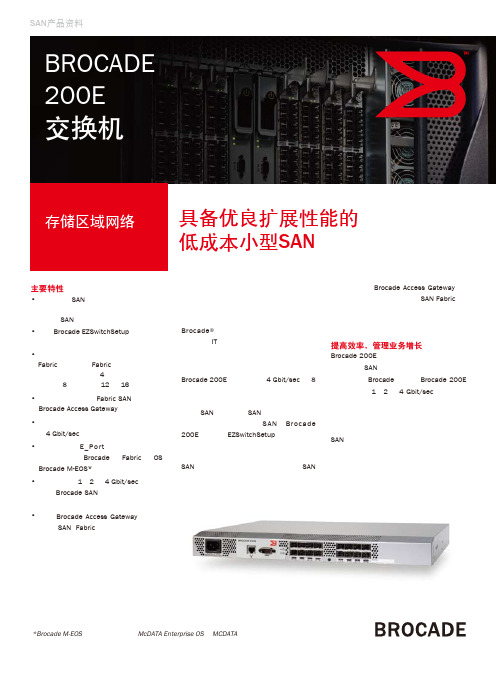
博科200E光纤交换机_官方产品资料Brocade_200E_switch_CN(博科官方)

*Brocade M-EOS结构是指所有运行McDATA Enterprise OS的 MCDATA交换机和导向器
Brocade Access Gateway模式
Brocade 200E既可用作完整Fabric 光纤通道SAN交换机,也可用作 Brocade Access Gateway。后者 带来了接入任何SAN的连接方式 (默认模式设置是交换机)。 各机构可以通过命令行界面、 Brocade Web Tools或 Brocade Fabric Manager,轻松设置 Brocade Access Gateway模式。
前后兼容 Brocade 200E 自带 E_Port 兼容性,可以 无 缝 地 连 接 到 Brocade Fabric OS® (FOS) 或 M-Enterprise OS (M-EOS)* 环境,因此 具有与现有 Brocade 交换机的完全互操作 性,使入门级和小型 SAN 能够胜任不同 需求,例如轻松应对电子邮件储存增长和 简 化 数 据 备 份 等。另 外,Brocade 200E 也可以和最新的 Brocade SAN 交换机和导 向器兼容,能在业务需要时,无缝隙并入 大型 “核心 - 边缘” SAN 网络构架。这些 功 能 使 Brocade 200E 成 为 一 些 关 键 性 SAN 解决方案的理想选择,例如 LAN-Free 备份以及服务器与存储系统集中等。
Brocade Access Gateway是一种 强大的Brocade Fabric OS功能, 可以实现无缝接入异构SAN环 境,可以增强Fabric伸缩性,并 简化管理。它有效利用N_Port ID Virtualization (NPIV) 功能,无缝地 将服务器与SAN连接起来,因此 通过一个解决方案,带来了与任 何SAN Fabric的互操作性。
光纤交换机配置(命令)

1.1.1.配置过程FC_SW1:admin> zonecreate "vm1","1,2;1,4"FC_SW1:admin> zonecreate "vm01","1,3;1,4"FC_SW1:admin> zonecreate "vm2","1,2;1,5"FC_SW1:admin> zonecreate "vm02","1,3;1,5"FC_SW1:admin> zonecreate "vm3","1,2;1,6"FC_SW1:admin> zonecreate "vm03","1,3;1,6"FC_SW1:admin> zonecreate "oadb1","1,2;1,7"FC_SW1:admin> zonecreate "oadb01","1,3;1,7"FC_SW1:admin> zonecreate "oadb2","1,2;1,8"FC_SW1:admin> zonecreate "oadb02","1,3;1,8"FC_SW1:admin> cfgcreate"conf1","vm1;vm2;vm3;oadb1;oadb2;vm01;vm02;vm03;oadb01;oadb02"FC_SW1:admin> cfgenable conf1You are about to enable a new zoning configuration.This action will replace the old zoning configuration with thecurrent configuration selected. If the update includes changesto one or more traffic isolation zones, the update may result inlocalized disruption to traffic on ports associated withthe traffic isolation zone changesDo you want to enable 'conf1' configuration (yes, y, no, n): [no] yzone config "conf1" is in effectUpdating flash ...FC_SW1:admin> cfgsaveYou are about to save the Defined zoning configuration. Thisaction will only save the changes on Defined configuration.Do you want to save the Defined zoning configuration only? (yes, y, no, n): [no] y Nothing changed: nothing to save, returning ...FC_SW1:admin > rebootWarning: This command would cause the switch to rebootand result in traffic disruption.Are you sure you want to reboot the switch [y/n]?yBroadcast message from root (pts/0) Mon Jun 7 05:14:18 2014...The system is going down for reboot NOW !!1.1.2.配置信息两台光纤交换机的配置相同,下面列举一台光交的配置FC_SW1:admin> zoneshowDefined configuration:cfg: conf1 vm1; vm2; vm3; oadb1; oadb2; vm01; vm02; vm03; oadb01; oadb02 zone: oadb01 1,3; 1,7zone: oadb02 1,3; 1,8zone: oadb1 1,2; 1,7zone: oadb2 1,2; 1,8zone: vm01 1,3; 1,4zone: vm02 1,3; 1,5zone: vm03 1,3; 1,6zone: vm1 1,2; 1,4zone: vm2 1,2; 1,5zone: vm3 1,2; 1,6alias: vnx5100 1,0; 1,1alias: vnx5300 1,2; 1,3Effective configuration:cfg: conf1zone: oadb01 1,31,7zone: oadb02 1,31,8 zone: oadb1 1,21,7 zone: oadb2 1,21,8 zone: vm01 1,31,4 zone: vm02 1,31,5 zone: vm03 1,31,6 zone: vm1 1,21,4 zone: vm2 1,21,5 zone: vm3 1,21,6。
光纤交换机配置详解

光纤交换机配置详解目录第1章S A N结构的存储区域(Z O N E)的规划 (2)第2章收集光纤交换机的配置信息 (5)2.1总体信息 (5)2.2Zone配置信息 (5)第3章网上参考文档 (6)3.1参考文档1 (6)3.2参考文档2 (7)3.3参考文档3 (8)第1章SAN结构的存储区域(ZONE)的规划在传统的没有SAN网络存在的系统中,网络中的各台主机是相互独立的,主机只能访问自己的硬盘,数据不会在存储级丧失安全性。
为了是SAN网络的可用性,在部署SAN架构的时候,一般都采用了冗余的架构,为了使这些可用的设备互不影响,,使主机访问存储设备路径的唯一性,需要对SAN架构中的存储设备,光纤交换机,主机划分不同的ZONE。
具体划分ZONE的方法详见下实例。
一号工程在实施之初大多数都采用如下的方案,这种方案存在一定的隐患,即光纤交换机没有冗余,这种方案如果不进行ZONE的设置,可能会导致系统不能使用存储阵列的情况。
我们建议个烟厂的系统管理员对一号工程的SAN网络进行检查,并对系统进行设置。
一.环境:DB2:HBA1/HBA2WAS:HBA1/HBA2FAST600:控制器A/控制器BSAN Switch: ibm h08或ibm h16二.配置原则:以一块HBA卡对应一个控制器的原则进行zone配置连接示意图三.具体配置操作步骤和方法:1. 用网线连接到交换机的管理口#telnet 10.77.77.77用户名:admin密码:password2. 查看交换机器端口连接#switchshowArea Port Media Speed State==============================0 0 id N2 Online F-Port 10:00:00:00:c9:42:a0:44(DB2_HBA1)1 1 id N2 Online F-Port 10:00:00:00:c9:45:b6:ea (DB2_HBA2)2 2 id N2 Online F-Port 20:05:00:a0:b8:18:d2:0a (WAS_HBA1)3 3 id N2 Online F-Port 20:04:00:a0:b8:18:d2:0a (WAS_HBA2)4 4 id N4 Online (控制器A)5 5 id N4 Online (控制器B)6 6 id N4 No_Light7 7 id N4 No_Light8 8 -- N4 No_Module (No POD License) Disabled3.划分zone输入以下命令zoneCreate "zone1","1,0;1,4"zoneCreate "zone2","1,1;1,5"zoneCreate "zone3","1,2;1,4"zoneCreate "zone4","1,3;1,5"cfgCreate "ibmp630","zone1;zone2; zone3; zone3"cfgEnable "ibmp630"cfgSave4.最后查看ZONE的划分做最后校验# zoneshowDefined configuration:cfg: ibmp630 zone1; zone1; zone1; zone1zone: zone1 1,0; 1,4 zone: zone2 1,1; 1,5 zone: zone3 1,2; 1,4 zone: zone4 1,3;1,5 Effective configuration: cfg: ibmp630zone: zone1 1,01,4 zone: zone2 1,11,5 zone: zone3 1,21,4 zone: zone4 1,31,5第1章收集光纤交换机的配置信息1.1 总体信息#switchshow例子1:例子2:1.2 Zone配置信息#zoneshow例子1:例子2:第2章网上参考文档2.1 参考文档1来源:/logs/14713887.html在SAN的环境中,光纤交换机(FC Switch)起着至关重要的作用,而FC Switch 的配置目前有GUI界面和CLI两种方式,GUI界面操作简单,但是花费时间较长,适合做较少配置时使用;CLI配置操作相对复杂,但是效率高,适合做大量配置时使用。
光交换机配置

光交换机配置dis cu#version 7.1.045, Release 2418P01#sysname H3C#telnet server enable#irf mac-address persistent timerirf auto-update enableundo irf link-delayirf member 1 priority 1irf mode normal#lldp global enable#system-working-mode advancepassword-recovery enable#fcoe-mode fcf#fc wwn 50:05:07:68:02:16:77:2b default-fc4-type scsi-fcp feature targetfc wwn 50:05:07:68:02:16:77:2c default-fc4-type scsi-fcp feature target#vsan 1#vsan 10zone default-zone permit#vsan 11zone default-zone permit#vsan 12zone default-zone permit#vsan 100zone name cc-1member pwwn 10:00:00:00:c9:a2:8c:8b member pwwn 50:05:07:68:02:16:77:2b zone name cc-2member pwwn 10:00:00:00:c9:a2:8c:8b member pwwn 50:05:07:68:02:16:77:2c zone name cc-2-1member pwwn 10:00:00:00:c9:a2:8c:3e member pwwn 50:05:07:68:02:16:77:2c zone name cc-2-2member pwwn 10:00:00:00:c9:a2:8c:3e member pwwn 50:05:07:68:02:16:77:2b zone name cc-3-1member pwwn 10:00:00:00:c9:a2:8c:9d member pwwn 50:05:07:68:02:16:77:2b zone name cc-3-2member pwwn 10:00:00:00:c9:a2:8c:9d member pwwn 50:05:07:68:02:16:77:2c zoneset name CCmember cc-1member cc-2-1member cc-2-2member cc-3-1member cc-3-2zoneset activate name CCdelete zone database allzone name cc-1member pwwn 10:00:00:00:c9:a2:8c:8b member pwwn 50:05:07:68:02:16:77:2b zone name cc-2member pwwn 10:00:00:00:c9:a2:8c:8b member pwwn 50:05:07:68:02:16:77:2c zone name cc-2-1member pwwn 10:00:00:00:c9:a2:8c:3e member pwwn 50:05:07:68:02:16:77:2c zone name cc-2-2member pwwn 10:00:00:00:c9:a2:8c:3e member pwwn 50:05:07:68:02:16:77:2b zone name cc-3-1member pwwn 10:00:00:00:c9:a2:8c:9d member pwwn 50:05:07:68:02:16:77:2b zone name cc-3-2member pwwn 10:00:00:00:c9:a2:8c:9d member pwwn 50:05:07:68:02:16:77:2c zoneset name CCmember cc-1member cc-2member cc-2-1member cc-2-2member cc-3-2#vlan 1#vlan 10fcoe enable vsan 10#vlan 11fcoe enable vsan 11#vlan 12fcoe enable vsan 12#vlan 100fcoe enable vsan 100#interface NULL0#interface FortyGigE1/0/1 port link-mode bridge#interface FortyGigE1/0/2 port link-mode bridge#interface FortyGigE1/2/25 port link-mode bridge#interface FortyGigE1/2/26 port link-mode bridgeinterface M-GigabitEthernet0/0/0ip address 10.20.141.49 255.255.255.0 #interface Fc1/2/1port access vsan 100#interface Fc1/2/2port access vsan 100#interface Fc1/2/3port access vsan 100#interface Fc1/2/4port access vsan 100#interface Fc1/2/5port access vsan 100#interface Fc1/2/6port access vsan 100#interface Fc1/2/7port access vsan 100#interface Fc1/2/8port access vsan 100#interface Fc1/2/9port access vsan 100interface Fc1/2/10 port access vsan 100#interface Fc1/2/11 port access vsan 100 #interface Fc1/2/12 port access vsan 100 #interface Fc1/2/13 port access vsan 100 #interface Fc1/2/14 port access vsan 100 #interface Fc1/2/15 port access vsan 100 #interface Fc1/2/16 port access vsan 100 #interface Fc1/2/17 port access vsan 100 #interface Fc1/2/18 port access vsan 100 #interface Fc1/2/19port access vsan 100#interface Fc1/2/20port access vsan 100#interface Fc1/2/21port access vsan 100#interface Fc1/2/22port access vsan 100#interface Fc1/2/23port access vsan 100#interface Fc1/2/24port access vsan 100#scheduler logfile size 16#line class auxuser-role network-admin #line class vtyuser-role network-operator #line aux 0user-role network-admin #line vty 0 4authentication-mode scheme user-role network-operator#line vty 5 63user-role network-operator#radius scheme systemuser-name-format without-domain #domain system#domain default enable system#role name level-0description Predefined level-0 role #role name level-1description Predefined level-1 role #role name level-2description Predefined level-2 role #role name level-3description Predefined level-3 role #role name level-4description Predefined level-4 role #role name level-5description Predefined level-5 role#role name level-6description Predefined level-6 role #role name level-7description Predefined level-7 role #role name level-8description Predefined level-8 role #role name level-9description Predefined level-9 role #role name level-10description Predefined level-10 role #role name level-11description Predefined level-11 role #role name level-12description Predefined level-12 role #role name level-13description Predefined level-13 role #role name level-14description Predefined level-14 role #user-group system#local-user admin class managepassword hash $h$6$IF6xkjzlO7eu0xL6$V3308fEczt60O7UrMWLQTS1536sZtEW OR/z2GA9wPFZTFrUnSvkRac/9ru3PyxCnhk25Il1RUzopxV/dAQv uUA==service-type telnet httpauthorization-attribute user-role level-15authorization-attribute user-role network-operator#ip http enable#return。
EMC、光纤交换机及服务器配置过程总结v

EMC、光纤互换机及办事器配置历程总结目录1概述 (3)2光纤互换机配置 (4)现有光纤互换机信息 (4)sw01 (4)Sw02 (5)设备连接汇总表 (5)光纤互换机配置 (6)术语 (6)光纤互换机配置历程 (6)3办事器agent安装 (10) (10)安装Agent (10)安装powerpath ODM补丁 (11)安装powerpath (13)Linux AS4 (14)参数配置 (14)安装配置PowerPath (15)安装agent (15)Windows 2003 (15)安装PowerPath (15)安装Agent (22)4EMC配置 (27)EMC识别办事器 (28)RAID Group的创建 (29)LUN的创建 (30)Storage Group的创建 (31)LUN到办事器的分派 (32)5办事器识盘确认 (34) (34)Linux AS4 (34)Windows 2003 (34)版本记载1概述本文主要从实用的角度整个描述EMC的分别、光纤互换机的配置以及办事器的设置,最终实现SAN情况中办事器乐成分派EMC空间。
首先我们在光纤互换机上界说一些通道即zone,允许办事器与EMC通讯;其次EMC 能够识别到办事器并将EMC空间分别给办事器;最后办事器乐成识别到EMC分别的空间。
本文根据配置顺序对付配置历程中的步调一一描述:本文配置历程配景:p550DB、mttest、gfstest1、gfstest2四台办事器需要通过光纤互换机连接EMC,p550DB、mttest能且只能访问EMC分派的独立空间;gfstest1、gfstest2也能能且只能够访问EMC分别的独立空间。
2光纤互换机配置2.1 现有光纤互换机信息现有SAN网络中使用光纤互换机两台,具体信息如下:2.1.1sw012、端口物理连接如下:2.1.2Sw02互换机型号EMC Conectrix DS16B3,端口物理连接如下:2.1.3设备连接汇总表2.2 光纤互换机配置2.2.1术语配置Zone需要涉及到三个工具的配置Alias,Zone,Configuration:Alias可以把设备的WWN或Domain,Port声明为Alias,用于更好更直观的标示设备;同时当Zone中的某个成员调换时,如果界说了Alias,只要修改Alias的界说就可以调解Zone 中的成员,而不消修改Zone的配置。
迈普交换机基本配置

迈普交换机配置1、迈普设备配置基本命令用户名密码为:admin adminSwitch>enable //进入普通用户模式-只能看看Switch#config terminal //进入全局配置模式Switch(config)#vlan 70 //新建vlan 70Switch(config-If-Vlan70)#name guanli //将vlan70命名为guanli Switch(config-If-Vlan70)#ip address 172.17.202.21255.255.255.0//配置交换机管理地址Switch(config-If-Vlan70)#no shutdownSwitch(config-If-Vlan70)#exitSwitch(config)#ip route-static 0.0.0.0 0.0.0.0 172.17.202.1//配置交换机路由Switch(Config)#vlan 338,440 //新建vlan338,440Switch(config)#int ethernet 0/0/1 //进入端口Switch(Config- Ethernet- 0/0/1)#no shutdown //打开端口Switch(Config- Ethernet- 0/0/1)#switchport mode access//将端口定义为access口Switch(Config- Ethernet- 0/0/1)#switchport access vlan 388//将vlan338加入该端口Switch(Config- Ethernet- 0/0/1)#exit //退出Switch(Config)# int ethernet 0/0/12-19;int ethernet 0/0/20 //进入端口组Switch(Config-Port-Range)#switchport mode access //将端口组定义为access口Switch(Config-Port-Range)#switchport access vlan 440//将vlan440加入该端口组Switch(Config-Port-Range)#exit //退出Switch(Config)# int ethernet 0/0/21 //进入端口Switch(Config- Ethernet-0/0/21)# switchport mode trunk//将端口定义为trunk口Switch(Config- Ethernet-0/0/21)#switchport trunk aaowed vlan70;338;440 //该端口允许Vlan70,338,440通过Switch(Config- Ethernet-0/0/21)exit //退出0/0/21 端口Switch(Config)# exit //退出.Switch#write //保存2、迈普设备故障处理基本命令1)查看交换机端口状态2)查看交换机端口描述3)查询mac地址4)修改交换机配置打开端口no shutdown关闭端口no shutdown迈普路由器配置与维护enable 普通用户模式只能看看特权用户模式:filesystem 文件系统模式configure 全局配置模式---- interface 接口配置模式router*** 路由配置模式ipsccess-list 访问列表配置模式voice-port 语音口配置模式dial-peer 拨号端口配置模式系统配置。
光纤交换机

interface fc1/9
port-license acquire
no shutdown
interface fc1/10
port-license acquire
no shutdown
interface fc1/11
port-license acquire
interface fc1/3
port-license acquire
no shutdown
interface fc1/4
port-license acquire
no shutdown
interface fc1/5
port-license acquire
no shutdown
snmp-server user admin network-admin auth md5 0x001f0ac42b8fd707a2a20902588bebdb
priv 0x001f0ac42b8fd707a2a20902588bebdb localizedkey
vsan databaserface fc1/23
interface fc1/24
interface mgmt0
ip address 192.168.1.1 255.255.255.0
switch# sh run
version 4.1(3a)
role name default-role
description This is a system defined role and applies to all users.
关于思科光纤交换机配置
大家好,我这边思科一个光纤交换机,是一个新的设备,我调试时连接服务器和存储的接口上的灯始终是黄色的。而连接苹果工作站的接口的灯是不亮的。我打环时交换机的等是可以绿色的。而且去掉交换机,服务器之间连接存储,这个存储也是可以看到的。就是接了这个思科光纤交换机就不通了。我咨询了其他人,说是我开始时那个引导没有做好,但是这个交换机如何设置成出厂默认值呀???开始时那些配置都配置什么呀??
光纤交换机配置

光纤交换机配置谈起交换机本地配置,首先我们来看一下交换机的物理连接。
交换机的本地配置方式是通过计算机与交换机的“Console”端口直接连接的方式进行通信的。
下面是店铺跟大家分享的是光纤交换机配置,欢迎大家来阅读学习。
光纤交换机配置工具/原料Windows电脑交换机第1步:1第1步:单击“开始”按钮,在“程序”菜单的“附件”选项中单击“超级终端”,弹出如图所示界面。
2第2步:双击“Hypertrm”图标,弹出如图所示对话框。
这个对话框是用来对立一个新的超级终端连接项。
3第3步:在“名称”文本框中键入需新建超的级终端连接项名称,这主要是为了便于识别,没有什么特殊要求,我们这里键入“Cisco”,如果您想为这个连接项选择一个自己喜欢的图标的话,您也可以在下图的图标栏中选择一个,然后单击“确定”按钮,弹出如图所示的对话框。
4第4步:在“连接时使用”下拉列表框中选择与交换机相连的计算机的串口。
单击“确定”按钮,弹出如图所示的对话框。
5第5步:在“波特率”下拉列表框中选择“9600”,因为这是串口的最高通信速率,其他各选项统统采用默认值。
单击“确定”按钮,如果通信正常的话就会出现类似于如下所示的主配置界面,并会在这个窗口中就会显示交换机的初始配置情况。
Catalyst 1900 Management ConsoleCopyright (c) Cisco Systems,Inc。
1993-1999All rights reserved。
Standard Edition SoftwareEthernet address:00-E0-1E-7E-B4-40PCA Number:73-2239-01PCA Serial Number:SAD01200001Model Number:WS-C1924-ASystem Serial Number:FAA01200001User Interface Menu[M] Menus//主配置菜单[I] IP Configuration//IP地址等配置[P] Console Password //控制密码配置Enter Selection://在此输入要选择项的快捷字母,然后按回车键确认至此就正式进入了交换机配置界面了,下面的工作就可以正式配置交换机了。
迈普交换机配置

迈普交换机配置迈普交换机基本配置一. 基本配置进入特权模式:Switch> enSwitch#进入全局模式:Switch# config terminalSwitch(Config)#退出命令exit举例:Switch#exitSwitch>帮助命令help举例:Switch>helpenable -- Enable Privileged modeexit -- Exit telnet session时钟配置:clock set功能:设置系统日期和时钟。
参数:为当前时钟,HH 取值范围为0~23,MM 和SS 取值范围为0~59;< YYYY/MM/DD >为当前年、月和日,YYYY取值范围为2000~2035,MM 取值范围为1~12,DD 取值范围为1~31。
举例:设置交换机当前日期为2002年8月1日23时0分0秒。
Switch# clock set 23:0:0 2002.8.1相关命令:show clock超时设置:exec timeout功能:设置退出特权用户配置模式超时时间。
参数:< minute >为时间值,单位为分钟,取值范围为0~300。
命令模式:全局配置模式。
缺省情况:系统缺省为5分钟。
使用指南:为确保交换机使用的安全性,防止非法用户的恶意操作,当特权用户在做完最后一项配置后,开始计时,到达设置时间值时,系统就自动退出特权用户配置模式。
数值为0表示没有超时。
举例:设置交换机退出特权用户配置模式的超时时间为6分钟。
Switch(Config)# exec timeout 6?修改交换机的主机名hostname XXX举例:设置提示符为Test。
Switch(Config)#hostname TestTest(config)#保存交换机配置的命令:write重启交换机的命令:reload恢复交换机出厂配置命令:set default举例:Switch#set defaultAre you sure? [Y/N] = ySwitch#writeSwitch#reload更改语言命令:language {chinese|english}功能:设置显示的帮助信息的语言类型。
光纤交换机配置详解

光纤交换机配置详解目录第1章S A N结构的存储区域(Z O N E)的规划 (2)第1章收集光纤交换机的配置信息 (6)1.1总体信息 (6)1.2Zone配置信息 (6)第2章网上参考文档 (7)2.1参考文档1 (7)2.2参考文档2 (8)2.3参考文档3 (14)第1章SAN结构的存储区域(ZONE)的规划在传统的没有SAN网络存在的系统中,网络中的各台主机是相互独立的,主机只能访问自己的硬盘,数据不会在存储级丧失安全性。
为了是SAN网络的可用性,在部署SAN架构的时候,一般都采用了冗余的架构,为了使这些可用的设备互不影响,,使主机访问存储设备路径的唯一性,需要对SAN架构中的存储设备,光纤交换机,主机划分不同的ZONE。
具体划分ZONE的方法详见下实例。
一号工程在实施之初大多数都采用如下的方案,这种方案存在一定的隐患,即光纤交换机没有冗余,这种方案如果不进行ZONE的设置,可能会导致系统不能使用存储阵列的情况。
我们建议个烟厂的系统管理员对一号工程的SAN网络进行检查,并对系统进行设置。
一.环境:DB2:HBA1/HBA2WAS:HBA1/HBA2FAST600:控制器A/控制器BSAN Switch: ibm h08或ibm h16二.配置原则:以一块HBA卡对应一个控制器的原则进行zone配置连接示意图三.具体配置操作步骤和方法:1. 用网线连接到交换机的管理口#telnet 用户名:admin密码:password2. 查看交换机器端口连接#switchshowArea Port Media Speed State==============================0 0 id N2 Online F-Port 10:00:00:00:c9:42:a0:44(DB2_HBA1)1 1 id N2 Online F-Port 10:00:00:00:c9:45:b6:ea (DB2_HBA2)2 2 id N2 Online F-Port 20:05:00:a0:b8:18:d2:0a (WAS_HBA1)3 3 id N2 Online F-Port 20:04:00:a0:b8:18:d2:0a (WAS_HBA2)4 4 id N4 Online (控制器A)5 5 id N4 Online (控制器B)6 6 id N4 No_Light7 7 id N4 No_Light8 8 -- N4 No_Module (No POD License) Disabled3.划分zone输入以下命令zoneCreate "zone1","1,0;1,4"zoneCreate "zone2","1,1;1,5"zoneCreate "zone3","1,2;1,4"zoneCreate "zone4","1,3;1,5"cfgCreate "ibmp630","zone1;zone2; zone3; zone3" cfgEnable "ibmp630"cfgSave4.最后查看ZONE的划分做最后校验# zoneshowDefined configuration:cfg: ibmp630 zone1; zone1; zone1; zone1 zone: zone1 1,0; 1,4zone: zone2 1,1; 1,5zone: zone3 1,2; 1,4zone: zone4 1,3;1,5Effective configuration:cfg: ibmp630zone: zone1 1,01,4zone: zone2 1,11,5 zone: zone3 1,21,4 zone: zone4 1,31,5第1章收集光纤交换机的配置信息1.1 总体信息#switchshow例子1:例子2:1.2 Zone配置信息#zoneshow例子1:例子2:第2章网上参考文档2.1 参考文档1来源:在SAN的环境中,光纤交换机(FC Switch)起着至关重要的作用,而FC Switch的配置目前有GUI界面和CLI两种方式,GUI界面操作简单,但是花费时间较长,适合做较少配置时使用;CLI配置操作相对复杂,但是效率高,适合做大量配置时使用。
光纤交换机配置详解

光纤交换机配置详解目录第1章S A N结构的存储区域(Z O N E)的规划 (2)第2章通过C L I命令Z O N I N G (6)第3章通过图形化界面Z O N I N G (7)第4章激活端口 (8)第5章收集光纤交换机的配置信息 (9)5.1总体信息 (9)5.2Zone配置信息 (9)第6章网上参考文档 (10)6.1参考文档1 (10)6.2参考文档2 (11)6.3参考文档3 (17)第1章SAN结构的存储区域(ZONE)的规划在传统的没有SAN网络存在的系统中,网络中的各台主机是相互独立的,主机只能访问自己的硬盘,数据不会在存储级丧失安全性。
为了是SAN网络的可用性,在部署SAN架构的时候,一般都采用了冗余的架构,为了使这些可用的设备互不影响,,使主机访问存储设备路径的唯一性,需要对SAN架构中的存储设备,光纤交换机,主机划分不同的ZONE。
具体划分ZONE的方法详见下实例。
一号工程在实施之初大多数都采用如下的方案,这种方案存在一定的隐患,即光纤交换机没有冗余,这种方案如果不进行ZONE的设置,可能会导致系统不能使用存储阵列的情况。
我们建议个烟厂的系统管理员对一号工程的SAN网络进行检查,并对系统进行设置。
一.环境:DB2:HBA1/HBA2WAS:HBA1/HBA2FAST600:控制器A/控制器BSAN Switch: ibm h08或ibm h16二.配置原则:以一块HBA卡对应一个控制器的原则进行zone配置连接示意图三.具体配置操作步骤和方法:1. 用网线连接到交换机的管理口#telnet 10.77.77.77用户名:admin密码:password2. 查看交换机器端口连接#switchshowArea Port Media Speed State==============================0 0 id N2 Online F-Port 10:00:00:00:c9:42:a0:44(DB2_HBA1)1 1 id N2 Online F-Port 10:00:00:00:c9:45:b6:ea (DB2_HBA2)2 2 id N2 Online F-Port 20:05:00:a0:b8:18:d2:0a (WAS_HBA1)3 3 id N2 Online F-Port 20:04:00:a0:b8:18:d2:0a (WAS_HBA2)4 4 id N4 Online (控制器A)5 5 id N4 Online (控制器B)6 6 id N4 No_Light7 7 id N4 No_Light8 8 -- N4 No_Module (No POD License) Disabled3.划分zone输入以下命令zoneCreate "zone1","1,0;1,4"zoneCreate "zone2","1,1;1,5"zoneCreate "zone3","1,2;1,4"zoneCreate "zone4","1,3;1,5"cfgCreate "ibmp630","zone1;zone2; zone3; zone3" cfgEnable "ibmp630"cfgSave4.最后查看ZONE的划分做最后校验# zoneshowDefined configuration:cfg: ibmp630 zone1; zone1; zone1; zone1 zone: zone1 1,0; 1,4zone: zone2 1,1; 1,5zone: zone3 1,2; 1,4zone: zone4 1,3;1,5Effective configuration:cfg: ibmp630zone: zone1 1,01,4zone: zone2 1,11,5 zone: zone3 1,21,4 zone: zone4 1,31,5第2章通过cli命令zoning第3章通过图形化界面zoning第4章激活端口第5章收集光纤交换机的配置信息5.1 总体信息#switchshow例子1:例子2:5.2 Zone配置信息#zoneshow例子1:例子2:第6章网上参考文档6.1 参考文档1来源:/logs/14713887.html在SAN的环境中,光纤交换机(FC Switch)起着至关重要的作用,而FC Switch 的配置目前有GUI界面和CLI两种方式,GUI界面操作简单,但是花费时间较长,适合做较少配置时使用;CLI配置操作相对复杂,但是效率高,适合做大量配置时使用。
光纤交换机及服务器配置过程总结

光纤交换机及服务器配置过程总结1. 光纤交换机配置过程光纤交换机是网络中重要的设备之一,它用于连接多台计算机或其他网络设备,并传输数据。
配置光纤交换机的过程如下:步骤1:连接光纤交换机首先,将光纤交换机与其他网络设备进行连接。
一般情况下,交换机的各个端口都是用于连接不同的设备。
步骤2:设置管理IP地址接下来,需要为光纤交换机设置管理IP地址,以便远程管理和监控交换机。
可以通过Telnet、SSH或Web界面等方式进行管理。
步骤3:创建VLAN(虚拟局域网)虚拟局域网(VLAN)是将交换机的端口划分成多个逻辑上独立的子网,可以增加网络安全性和管理灵活性。
在光纤交换机上,我们可以创建多个VLAN,然后将不同的端口划分到对应的VLAN中。
步骤4:配置端口在创建VLAN之后,需要配置交换机的端口。
可以设置端口的速率、双工模式、VLAN成员关系等参数,以适应不同的网络需求。
步骤5:配置交换机的路由功能(可选)一些高级的光纤交换机支持路由功能,可以实现不同VLAN之间的互通。
如果需要使用交换机的路由功能,需要进行相关配置。
步骤6:保存配置并重启交换机最后,保存交换机的配置,并重启交换机使配置生效。
2. 服务器配置过程服务器是用于存储和处理网络上的数据的设备,服务器的配置过程如下:步骤1:安装操作系统首先,根据服务器的硬件要求,选择合适的操作系统,并进行安装。
常见的服务器操作系统有Windows Server、Linux等。
步骤2:设置网络参数安装完操作系统后,需要设置服务器的网络参数,包括IP地址、子网掩码、网关等。
这些参数可以手动设置,也可以使用DHCP动态获取。
步骤3:安装服务器应用程序根据实际需求,安装服务器上需要运行的应用程序。
例如,如果是搭建Web服务器,需要安装Web服务软件(如Apache、Nginx等);如果是数据库服务器,需要安装数据库软件(如MySQL、Oracle等)。
步骤4:配置服务器应用程序安装完应用程序后,需要对其进行配置。
光纤交换机配置-命令模式

Zoning With CLI CommandsDell™ PowerVault™ 5x F Switches Zoning GuideCreating and Modifying Zone AliasesCreating and Modifying ZonesCreating and Modifying Zone ConfigurationsManaging a Zone ConfigurationYou can zone Dell™ PowerVault™ switches using Command Line Interface (CLI)commands by creating and managing the three principal zoning objecttypes—alias, zone, and configuration. You issue the commands during a Telnetsession with the switch(es). (Refer to your PowerVault switch Installation andTroubleshooting Guide for details on creating a Telnet session with the switch.)NOTE: Before issuing any zoning commands, use the switchShow command on each switch i are connected. All ports used for interswitch links (ISL) display the neighboring switches' WWN Follow this general sequence of steps when creating a new zone configuration.NOTE: See "Zoning Roadmap" in "Introduction" for additional guidelines on creating or managin1.Define the core aliases.2.Define all zones.3.Add aliases and members to the zones.4.Define the zone configuration.5.Add zones to the configuration.6.Enable the configuration.7.Test the configuration.8.Save the configuration.Including Multiple Items in a CLI CommandTo include multiple items in a CLI command, separate the items with semicolons,within a single pair of quotes:command "name_of_zoning_object", "member; member; member"For example, zoneAdd "Red_zone", "1,10;1,12" adds domain 1, port 10 anddomain 1, port 12 to zone "Red_zone".Creating and Modifying Zone AliasesWhile aliases are not required in a zone configuration, they can make it easier to manage complex configurations in your zone. After you create aliases, you can then move to the next section and create and configure zones.aliCreateThe following example shows three instances of the aliCreate command, which creates a new zone alias.aliDeleteThe following example shows the aliDelete command, which deletes an existing zone alias.aliAddThe following example shows three instances of the aliAdd command, which adds one or more new alias members to an existing zone alias and is a list of one or more physical-fabric port numbers (such as 1,2) or WWNs (such as10:00:00:60:69:00:00:8a) separated by semicolons.admin> aliAdd "array1", "21:00:00:20:37:0c:72:51;21:00:00:20:37:0c:71:0a"admin> aliAdd "array2", "21:00:00:20:37:0c:9c:6b;21:00:00:20:37:0c:66:3a"admin> aliAdd "loop1", "21:00:00:20:37:0c:6a:40;21:00:00:20:37:0c:59:7e"White spaces are ignored. The alias members list cannot contain references to any other zone aliases.aliRemoveThe following example shows the aliRemove command, which removes one or more members from an existing zone alias.The members to be removed are found by an exact string match. When removing multiple members, sequence is important. If this command results in all members being removed, the system deletes the zone alias.aliShowThe following example shows the aliShow command, which displays thespecified zone alias definition if a parameter is given (otherwise all zoneconfiguration information is displayed).Creating and Modifying ZonesYou can use the following CLI commands to create or manipulate the zones and their members with a fabric. These members may consist of fabric ports, WWNs, or aliases.zoneCreateUse this command to create a zone with one or more members. The following example shows thre instances of the zoneCreate command.zoneDeleteThe following example shows the zoneDelete command, which deletes anexisting zone.zoneAddThe following example shows the zoneAdd command, which adds one or morenew members to an existing zone.zoneRemoveThe following example shows the zoneRemove command, which removes one ormore members from an existing zone.The members to be removed are found by an exact string match. Therefore, whenremoving multiple members, sequence is important. If this command removes allmembers, the system deletes the zone.zoneShowThe following example shows the zoneShow command, which displays thespecified zone definition if a parameter is given (otherwise all zone configurationinformation is displayed).Creating and Modifying Zone ConfigurationsAfter creating zones, you can create or remove zone configurations and their members using CLI commands.cfgCreateThe following example shows the cfgCreate command, which creates a new zone configuration.cfgDeleteThe following example shows the cfgDelete command, which deletes an existingzone configuration.cfgAddThe following example shows the cfgAdd command, which adds one or more new zones to an existing zone configuration.cfgRemoveThe following example shows the cfgRemove command, which removes one or more zones from an existing zone configuration.The zones to be removed are found by an exact string match. When removing multiple members, sequence is important. If this command removes all members, the system deletes the zone configuration.cfgShowThe following example shows the cfgShow command, which displays the specified zone configuration definition if a parameter is given (otherwise, all zone configuration information is displayed)Adding a New Device to a Configuration1.Create an alias for the device by typingaliCreate "alias_name", WWN (or port number)2.Add the alias to the appropriate zone(s) by typingzoneAdd "zone_name", "alias_name"3.Save the configuration by typingcfgSave "config_name"4.Enable the configuration by typingcfgEnable "config_name"Removing a Device From a Zone Configuration1.Remove the device from the zone:a.If there is only one device in the alias, typezoneRemove "zone_name", "alias_name"a.If you are removing a single device from an alias that includesseveral devices, typezoneRemove "zone_name", "alias_name", WWN (or port number)a.To remove multiple devices, type aliRemove "alias_name", followedby the WWN (or port number) of each device you are removing.2.Save the new configuration by typingcfgSave "config_name"3.Enable the configuration by typingcfgEnable "config_name"Replacing a Device in a Zone Configuration1.Remove the existing device from the zone:a.If you are replacing a single device in an alias that includes severaldevices, remove the device you are replacing by typingzoneRemove "zone_name", "alias_name", WWN (or port number)a.If the device you wish to replace is the only device in the alias, typezoneRemove "zone_name", "alias_name"a.To replace multiple devices, type aliRemove "alias_name", followedby the WWN (or port number) of each device you wish to replace.2.If desired, create an alias for the replacement device by typingaliCreate "alias_name", WWN (or port number)3.Add the device or alias to the appropriate zone(s) by typingzoneAdd "zone_name", "zone member name"orzoneAdd "zone_name", "alias_name"4.Save the configuration by typingcfgSave "config_name"5.Enable the configuration by typingcfgEnable "config_name"Managing a Zone ConfigurationAfter creating the zone configuration, use the following commands to enable, save,disable, or clear the zone configuration.cfgSaveThe following example shows the cfgSave command, which writes a copy of thedefined configuration and the name of the effective configuration to flash memoryin all fabric switches.The saved configuration is automatically reloaded by the switch at system startup.If a configuration was in effect when it was saved, the same configuration isreinstated with an automatic cfgEnable command.NOTE: Dell recommends saving after you enable and test a configuration. Any unsaved configu cfgEnableThe following example shows the cfgEnable command, which enables aspecified configuration.cfgDisableThe following example shows the cfgDisable command, which disables thecurrent zone configuration.The fabric returns to a nonzoned mode, in which all devices see each other.cfgClearThe following example shows the cfgClear command, which you should use withcaution.NOTICE: When executed on any switch in the fabric, the cfgClearcommand removes all alias, zone, and configuration information from allswitches in the fabric. Dell recommends clearing any switch beforeconnecting it to a zoned fabric.When the cfgClear command is used on an enabled zone configuration, it is firstdisabled. The system then deletes all defined zone objects. However, the savedconfiguration remains in flash memory. To clear the configuration from memory,type cfgSave after cfgClear and press <Enter>.。
迈普交换机系统配置基础

迈普交换机系统配置基础系统模式系统模式及其相互间切换方法(switch 是设备出厂时缺省的系统名称,用户可以在全局配置模式下运行hostname 命令修改系统名称,并且这种修改是立即生效的)实验一通过配置口(Console)配置交换机实验步骤:1、选择一台终端终端既可以是标准的具有RS-232串口的终端,也可以是一台普通的PC机,更常用的是后者。
如果要从远端配置,则还需两台MODEM。
2 、在确认交换机或终端其中至少有一方是关机的情况下,通过配置电缆将终端的RS-232串口与交换机Console口相连。
接线关系如图所示:3、给终端上电。
设置终端通信参数为波特率9600bps、8 位数据位、1 位停止位、无校验和XON/XOFF。
如果是PC 机,运行Win95/98/2000/NT 操作系统,则运行HyperTerminal(超级终端)程序,并按照以上参数设置超级终端程序的串口参数。
下面以WindowsXP的终端超级终端程序为例图示说明:a.为连接填写名称――MP_S3400(可以是其它任意名称),并为所建连接选择一个Windows图标。
b.选择串行通信口c.配置串行通信口参数波特率——9600bps数据位——8位奇偶校验——无停止位——1位流控——xon/xoffd.登录成功后会在终端上显示“switch>”提示符;就可以对交换机进行配置了。
实验二命令行接口命令行接口是shell子系统为用户配置、使用交换机而提供的一个人机交互界面,用户通过命令行接口可以输入、编辑命令来完成相应的配置任务,同时也可以通过该接口查看系统信息,了解系统运行状况。
命令行接口为用户提供了如下功能:●系统帮助信息管理●系统命令输入、编辑●接口历史命令管理●终端显示系统管理实验步骤:a.在任一命令模式下,键入“?”获取该命令模式下所有命令及其简单描述。
实验步骤:b. 键入一命令,后接以空格分隔的“?”,则显示出所有该命令在当前模式下可以执行的子命令。
迈普交换机配置

迈普交换机配置迈普交换机配置1、配置举例2、配置交换机名称为“Switch_1”。
语法描述Switch>enable 进入到Enable模式Switch#configure terminal 进入到全局配置模式Switch(config)#hostname Switch_1 配置交换机名称3、设置enable密码(config t 模式下):enable password [0 | 7 ] string 设置enable密码,string为所要配置的密码4、创建VLAN:vlan [vlan-num]语法描述vlan-num 打开VLAN命令,并进入到VLAN配置模式,值的范围为1~40945、添加VLAN描述:description string string为所增加描述的内容6、在VLAN下添加端口:port port-list untag| tag 配置端口为打标模式或不打标模式7、在端口下绑定PVID号(也就是端口的默认VLAN号):pvid pvid-num 在端口配置模式下配置(port下)8、启用全局的igmpsnoop:igmpsnoop enable9、在端口下禁用广播风暴抑制功能:storm-control disable10、交换机三网合一配置Switch#show run //查看配置vlan 1 //删除vlan 1中的端口description defaultport 0/0-0/7untaggedvlan 20description VLAN 20 /创建上网VLAN 20port 0/0 tagged /tagged为打标也就是trunkport 0/1 untagged /untagged为非打标也就是accessport 0/1 pvid 20 /设置端口1的PVID为20vlan 2103description VLAN2103 /创建电话VLAN 2103port 0/0 tagged /tagged为打标也就是trunkport 0/2 untagged /untagged为非打标也就是accessport 0/2 pvid 2103 /设置端口2的PVID为2103vlan 2104description VLAN2104 /创建IPTV VLAN 2104port 0/0 tagged /tagged为打标也就是trunkport 0/3-0/6 untagged /untagged为非打标也就是accessport 0/3-0/6 pvid 2104 /设置端口3-6的PVID为2104exit /退出igmpsnoop enable /开启IGMP组播功能Spanning-tree disable /关闭生成树协议port 0/0storm-control disable /广播风暴控制抑制功能关闭exit /退出wr /保存11、端口环路配置迈普交换机环路检测功能需要在端口下配置:keepalive ,举例说明比如您要在0/1端口下开启端口环路检测功能的话port0/1keepalive 100 //其中100为时间,单位是秒,此命令的意思是每100秒检测一次端口环路12、清空配置迈普交换机清空配置的命令为:在特权模式下也就是#后输入filesystem 回车,然后 dir 可以看到显示出来的文件有个叫startup的,这个文件就是存储配置的文件,把这个文件删除就可以清空配置,使用命令delete startup 将startup文件删除,然后再关电重新启动交换机即可。
光纤交换机级联配置文档CISCO

光纤交换机级联配置文档Cisco 9120交换机1.配置异构交换机平台协同工作模式Cisco 9120配置过程激活前8个端口switch# config tEnter configuration commands, one per line. End with CNTL/Z. switch(config)#interface fc1/1-8switch(config-if)# no shutdownswitch(config-if)# end配置交换机协同工作模式switch# config tEnter configuration commands, one per line. End with CNTL/Z. switch(config)# vsan databaseswitch(config-vsan-db)# vsan 1 interopswitch(config-vsan-db)# end配置domain IDswitch# config tEnter configuration commands, one per line. End with CNTL/Z. switch(config)# fcdomain domain 100 preferred vsan 1switch(config)# end激活VSANswitch# config tEnter configuration commands, one per line. End with CNTL/Z. switch(config)# vsan databaseswitch(config-vsan-db)# vsan 1 suspendswitch(config-vsan-db)# no vsan 1 suspendswitch(config-vsan-db)# end察看修改之后的系统配置信息switch# show runningversion 2.0(2b)vsan databasevsan 1 interop 1fcdomain domain 100 preferred vsan 1fcdomain fcid persistent vsan 1boot kickstart bootflash:/m9100-s1ek9-kickstart-mz.2.0.2b.bin boot system bootflash:/m9100-s1ek9-mz.2.0.2b.binkernel core target 0.0.0.0kernel core limit 1snmp-server user admin network-admin auth md5 0xeec64ba2afbe9b65e13b23882ac6ae05priv 0xeec64ba2afbe9b65e13b23882ac6ae05 localizedkeyusername admin password 5 $1$V3smTQpb$MTvub69DkVBxdCt9BsEDB1 role network-admincallhomeswitch-priority 7snmp-server enable traps licenseinterface mgmt0ip address 192.168.70.139 255.255.255.0interface fc1/1no shutdowninterface fc1/2no shutdowninterface fc1/3no shutdowninterface fc1/4no shutdowninterface fc1/5no shutdowninterface fc1/6no shutdowninterface fc1/7no shutdowninterface fc1/8no shutdowninterface fc1/9interface fc1/10interface fc1/11interface fc1/12interface fc1/13interface fc1/14interface fc1/15interface fc1/16interface fc1/17interface fc1/18interface fc1/19interface fc1/20switch#察看端口连接状态信息switch# show interface brief------------------------------------------------------------------------------- Interface Vsan Admin Admin Status FCOT Oper Oper Port Mode Trunk Mode Speed ChannelMode (Gbps)-------------------------------------------------------------------------------fc1/1 1 auto on up swl F 2 --fc1/2 1 auto on up swl F 2 --fc1/3 1 auto on up swl E 2 --fc1/4 1 auto on notConnected swl -- --fc1/5 1 FX -- notConnected swl -- --fc1/6 1 FX -- notConnected swl -- --刀片中心光纤交换机模块配置禁止交换机brocadessm:USERID> switchdisable修改Domain IDbrocadessm:USERID> configureConfigure...Fabric parameters (yes, y, no, n): [no] yesDomain: (1..239) [1] 99R_A_TOV: (4000..120000) [10000]E_D_TOV: (1000..5000) [2000]WAN_TOV: (0..30000) [0]MAX_HOPS: (7..19) [7]Data field size: (256..2112) [2112]Sequence Level Switching: (0..1) [0]Disable Device Probing: (0..1) [0]Suppress Class F Traffic: (0..1) [0]Switch PID Format: (1..2) [1]Per-frame Route Priority: (0..1) [0]Long Distance Fabric: (0..1) [0]BB credit: (1..27) [16]Insistent Domain ID Mode (yes, y, no, n): [no]Virtual Channel parameters (yes, y, no, n): [no]Zoning Operation parameters (yes, y, no, n): [no]RSCN Transmission Mode (yes, y, no, n): [no]Arbitrated Loop parameters (yes, y, no, n): [no]System services (yes, y, no, n): [no]Portlog events enable (yes, y, no, n): [no]ssl attributes (yes, y, no, n): [no]http attributes (yes, y, no, n): [no]snmp attributes (yes, y, no, n): [no]rpcd attributes (yes, y, no, n): [no]cfgload attributes (yes, y, no, n): [no]webtools attributes (yes, y, no, n): [no]WARNING: The domain ID will be changed. The port level zoning may be affectedbrocadessm:USERID> msPlMgmtDeactivateSwitch is in Offline state.修改协同工作模式brocadessm:USERID> interoper mode 1The switch effective configuration will be lost when the operating mode is changed; do you want to continue? (yes, y, no, n): [no] yInteropmode is enabledNote: It is recommended that you reboot this switch for the new change to take effect.重新引导交换机brocadessm:USERID> fastbootBroadcast message from root (pts/0) Tue Jun 13 10:07:45 2006...The system is going down for reboot NOW !!USERIDPassword:Please change your passwords now.Use Control-C to exit or press 'Enter' key to proceed.Password was not changed. Will prompt again at next loginuntil password is changed.brocadessm:USERID>brocadessm:USERID> switchenable察看修改配置之后的交换机状态brocadessm:USERID> switchshowswitchName: brocadessmswitchType: 22.0switchState: OnlineswitchMode: InteropswitchRole: PrincipalswitchDomain: 99switchId: fffc63switchWwn: 10:00:00:05:1e:02:78:c6zoning: OFFswitchBeacon: OFFArea Port Media Speed State==============================0 0 id 2G No_Light1 1 cu 2G Online F-Port 21:00:00:14:5e:24:a9:042 2 cu 2G Online F-Port 21:00:00:14:5e:24:a9:363 3 cu 2G Online F-Port 21:00:00:14:5e:24:a9:7a4 4 cu 2G Online F-Port 21:00:00:14:5e:24:a9:b65 5 cu 2G Online F-Port 21:00:00:14:5e:24:a9:286 6 cu 2G Online F-Port 21:00:00:14:5e:24:aa:f67 7 cu 2G Online F-Port 21:00:00:14:5e:24:aa:f08 8 cu 2G Online F-Port 21:00:00:14:5e:24:a9:389 9 cu 2G No_Light10 10 cu 2G No_Light11 11 cu 2G No_Light12 12 cu 2G No_Light13 13 cu 2G No_Light14 14 cu 2G No_Light15 15 id 2G Online E-Port 20:01:00:0d:ec:06:b4:41 (downstream)2.划分zoneCisco 9120划分zone察看fabric连接设备port wwn 信息switch# show fcns database vsan 1--------------------------------------------------------------------------FCID TYPE PWWN (VENDOR) FC4-TYPE:FEATURE--------------------------------------------------------------------------0x630100 N 21:00:00:14:5e:24:a9:04 scsi-fcp0x630200 N 21:00:00:14:5e:24:a9:36 scsi-fcp0x630300 N 21:00:00:14:5e:24:a9:7a scsi-fcp0x630400 N 21:00:00:14:5e:24:a9:b6 scsi-fcp0x630500 N 21:00:00:14:5e:24:a9:28 scsi-fcp0x630600 N 21:00:00:14:5e:24:aa:f6 scsi-fcp0x630700 N 21:00:00:14:5e:24:aa:f0 scsi-fcp0x630800 N 21:00:00:14:5e:24:a9:38 scsi-fcp0x640000 N 20:07:00:a0:b8:21:19:9f (SymBios) scsi-fcp:both0x640100 N 20:06:00:a0:b8:21:19:9f (SymBios) scsi-fcp:bothTotal number of entries = 10创建zone分别创建2个zone,前4个刀片服务器与DS4300 2个控制器组成的zone,第4到第8个刀片服务器与DS4300 2个控制器组成的zone。
光纤交换机的配置

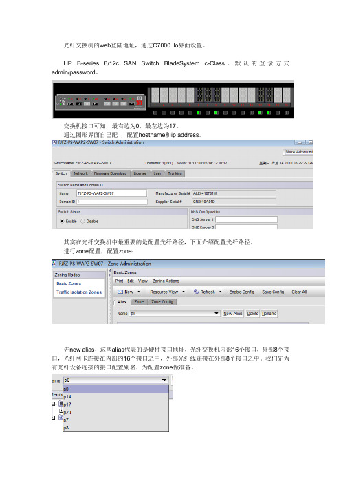
光纤交换机的web登陆地址,通过C7000 ilo界面设置。
HP B-series 8/12c SAN Switch BladeSystem c-Class,默认的登录方式admin/password。
交换机接口可知,最右边为0,最左边为17。
通过图形界面自己配,配置hostname和ip address。
其实在光纤交换机中最重要的是配置光纤路径,下面介绍配置光纤路径。
进行zone配置,配置zone:
先new alias,这些alias代表的是硬件接口地址,光纤交换机内部16个接口,外部8个接口,光纤网卡连接在内部的16个接口之中,外部光纤线连接在外部8个接口之中。
我们先为有光纤设备连接的接口配置别名,为配置zone做准备。
再将相应的接口加入到alias中。
再添加域:
添加路径:(这些路径要根据实际情况来定)
sw07 p0指的是外接的端口0(DA02 SPA0)p7 指的内接(db05)p8指的是内接(db06) p14指的是内接的sv04(备份主机) p17指的是外接的端口17(DA02 SPB1)
p20指的是外接的端口20(TP01 SPA0)
所以添加路径为P14和p20相连,p7分别于p17和p0相连,p8同理冗余机制。
根据具体情况来配置路径。
最后需要保存这些config:先需要新建config,然后使能,add port zone to new zone and enable new zone config for each fibre switch。
然后先保存config,再使能config就行了。
- 1、下载文档前请自行甄别文档内容的完整性,平台不提供额外的编辑、内容补充、找答案等附加服务。
- 2、"仅部分预览"的文档,不可在线预览部分如存在完整性等问题,可反馈申请退款(可完整预览的文档不适用该条件!)。
- 3、如文档侵犯您的权益,请联系客服反馈,我们会尽快为您处理(人工客服工作时间:9:00-18:30)。
第 2 页 共 12 页
Mcdata 光纤通道交换机配置
光纤网络服务
诊断
可维护性
物理尺寸 宽度 高度 厚度 安装选项 环境 非工作状态
工作状态
电气 工作电压 电流 功率 规定
简单名字服务器 按需供应(2、3 类) 管理服务器(可选) 广播 名字服务器分区 加电自检(POST) 联机端口诊断、内部和外部回送 联机系统健康状况诊断 热插拔电源和冷却模块 热插拔光学器件 HotCAT 固件升级 Call-Home、E-mail 报警(借助 McDATA 的软件) 维护端口 过热事件记录 机箱、端口、FRU 标示 系统错误 LED FRU 故障 LED
Mcdata 光纤通道交换机配置
一、MCDATA 光纤通道交换机介绍
2006 年 Mcdata 公司已经被 Brocade(博科)公司收购,原 MCDATA 中低端产品线的光 纤通道交换机现在正使用的有 2GB 和 4GB 接口速度的,2GB 接口速度的产品有 2026-E12 和 2026-224 两款,4GB 接口速度有 2026-416 和 2026-432 两款产品。
1.0625 – 2.125 Gb/s,全双工 96Gb/s 平均不超过 1 微秒
24 个 GL 端口 热插拔业界标准 LC 小接口(SFP) 短波:500 米 (1640 英尺) 长波:10 公里 (6.2 英里) (最多可以 有 4 个端口支持长波) 9/125 微米单模式,10 公里 50/125 微米多模式,500 米 62.5/125 微米多模式,300 米 SANpilot 光纤网络管理——基于浏览器 McDATA 软件 SNMP 开放式系统管理服务器 命令行界面 In-Band 管理 以太网(10/100Mb/s)
管理选项
管理访问
HotCAT 联机不中断应用的固件升级 可热插拔的冗余电源、冷却装置 热插拔小接口(SFP)收发器 联机诊断 针对整个网络的活动的故障隔离工具
FC-PH Rev4.3,FC-PH-2,FC-PH-3,FC-GS-2,FC-FLA,FC-FG,FC-SW-2 光纤联盟 MIB,光纤通道网络组件 MIB,TCP-IP MIB II 二类、三类、F 类
FC 4411 - SAN16M-2 SANtegrity Enhanced
FC 4420 - SAN16M-2 Open Trunking
FC 4450 - SAN16M-2 Full Volatility
IBM 2026-432 产品的性能与特性与 2026-416 差不多
二、MCDATA 产品配置
相对湿度
8% 至 80%
电源需求
电源范围
90 至 264V 交流电,47-63Hz
产品号
2026 416 型 - IBM SAN16M-2 光纤交换机,带 16 个端口(G_Port);双电源;双电源线
FC 4401 - 4ports Flexport 增加 4 个 4Gbps 短波端口
FC 4410 - SAN16M-2 Element Manger
默认状态下 MCDATA 光纤通道交换机的各个接口是不联通,为了让某几个接口能够 通信,我们必须对它进行相关配置,划分合适的 ZONE。MADATA 出厂的管理 IP 为 10.1.1.10 ,我们可以通过 WEB 界面对它进行配置。详细的配置界面如下
第 4 页 共 12 页
Mcdata 光纤通道交换机配置
第 3 页 共 12 页
Mcdata 光纤通道交换机配置
物理特点
尺寸
高度(机柜安装)
4.1cm/1.6in
宽度
19.9cm/7.8in
ห้องสมุดไป่ตู้长度
33.3cm/13.1in 增加 6.1cm/2.4in 冗余电源
重量
4.0kg/8.8lb
操作环境
温度
4.40°C 至 40°C/(40°F 至 104°F)
Mcdata 光纤通道交换机配置 第 9 页 共 12 页
Mcdata 光纤通道交换机配置 第 10 页 共 12 页
Mcdata 光纤通道交换机配置 第 11 页 共 12 页
Mcdata 光纤通道交换机配置 第 12 页 共 12 页
BM TotalStorage SAN12M-1(2026-E12)是一款简单但高效率的入门级 SAN 解决方 案产品,它拥有无与伦比的产品互操作能力和兼容性能力。可以“按需付费”地配置 4 端口、 8 端口、或 12 端口。
第 1 页 共 12 页
Mcdata 光纤通道交换机配置
IBM 的 24(8-16-24)端口 TotalStorage 2026-224 可以利用先进的 Flexport 技术,提供
IBM 提供的(2026-416)SAN16M-2 交换机是以行业领先的 16 端口模型提供的。IBM TotalStorage SAN 交换机可提供 4 GB/秒的光纤通道容量和性能及高级功能,当 SAN 网络从 入门级工作组网络扩展为拥有数以千计设备的核心-边缘网络时,这些特性可满足其对改进 安全性、性能和易管理性的要求。该型号光纤交换机被设计成利用可热插拔的、分担负载的 双电源(通过双电源,交换机可以在一个电源发生故障的情况下仍保持联机)来提供高可用 性,并在需要微码升级时提供并发代码激活。
17”(可安装于 19”机柜) 1.75”(1U) 17.5” 可机柜安装,19 英寸 EIA 机柜 桌面可堆叠
温度: 40°至 125°F 湿度:8%-80% 高度:40000 英尺 温度:40°至 104°F 湿度:8%-80% 高度:10000 英尺
100-230VAC 通常 1.25-0.67AMP,最大 2AMP 不超过 50 瓦 UL, TUV, CE Mark, VCCI Class A, FCC part 15 Class A
前所未有的按需连接。您可以购买您目前所需要的端口数,同时为将来的发展储备好足够的
端口容量。不需中断系统工作,就可以现场添加端口容量。凭借它的“根据增长速度付费”
的优点和对环路式与交换式光纤通道的支持,它是中小型企业(SME)建设 SAN 的理想构成
组件。 可用性
兼容性 光纤通道协议 SNMP 光纤通道服务类别 性能 端口速度 总吞吐量 延迟 可扩展性 每个机箱的端口数 介质类型 所支持的光介质类型/ 距离 电缆铺设
user:Administrator password:password
第 5 页 共 12 页
Mcdata 光纤通道交换机配置
按 switch details
第 6 页 共 12 页
Mcdata 光纤通道交换机配置 第 7 页 共 12 页
Mcdata 光纤通道交换机配置 第 8 页 共 12 页
