交换机 vrrp+mstp配置实例,含均衡负载(大赛人原文)
mstp加vrrp的实验例子
mstp加vrrp的实验例子(原创实用版)目录1.MSTP 和 VRRP 的概述2.MSTP 加 VRRP 的实验环境搭建3.实验步骤和过程4.实验结果及分析5.实验结论和展望正文一、MSTP 和 VRRP 的概述1.MSTP(Multiple Spanning Tree Protocol):多实例生成树协议,用于在多个 VLAN(虚拟局域网)之间实现生成树保护。
2.VRRP(Virtual Router Redundancy Protocol):虚拟路由器冗余协议,用于提高网络设备的可靠性和冗余性。
二、MSTP 加 VRRP 的实验环境搭建1.设备:两台路由器(Router1 和 Router2),一台交换机(Switch)2.接口:Router1 的接口 G0/0/1 和 G0/0/2 分别连接到 Switch 的接口 1 和 2;Router2 的接口 G0/0/1 和 G0/0/2 分别连接到Switch 的接口 3 和 4。
3.配置:为每个接口分配不同的 VLAN,如 G0/0/1 为 VLAN10,G0/0/2 为 VLAN20。
三、实验步骤和过程1.在 Router1 上配置 MSTP 和 VRRP:a.配置 MSTP:在 Router1 上启用 MSTP,将 G0/0/1 和 G0/0/2 分别配置为 MSTP 的实例 1 和实例 2。
b.配置 VRRP:在 Router1 上启用 VRRP,将 G0/0/1 和 G0/0/2 分别配置为 VRRP 的虚拟路由器 1 和虚拟路由器 2。
2.在 Router2 上配置 MSTP 和 VRRP:a.配置 MSTP:在 Router2 上启用 MSTP,将 G0/0/1 和 G0/0/2 分别配置为 MSTP 的实例 1 和实例 2。
b.配置 VRRP:在 Router2 上启用 VRRP,将 G0/0/1 和 G0/0/2 分别配置为 VRRP 的虚拟路由器 1 和虚拟路由器 2。
VRRP+MSTP配置案例

H3C 7503-A<SwitchA> system-view[SwitchA] bfd echo-source-ip 11.11.11.11[SwitchA]vlan 10 20 30 40 50 60 70 80 90 4094[SwitchA] interface GigabitEthernet2[SwitchA-GigabitEthernet2] port link-type trunk[SwitchA-GigabitEthernet2] port trunk permit vlan 10 to 90[SwitchA] interface GigabitEthernet3[SwitchA-GigabitEthernet3] port link-type trunk[SwitchA-GigabitEthernet3] port trunk permit vlan 10 to 90[SwitchA] interface vlan-interface 4094[SwitchA-Vlan-interface4094] ip address 192.168.100.254 24[SwitchA] interface vlan-interface 10[SwitchA-Vlan-interface10] ip address 192.168.10.1 24[SwitchA-Vlan-interface10] vrrp vrid 10 virtual-ip 192.168.10.254 24[SwitchA-Vlan-interface10] vrrp vrid 10 priority 120[SwitchA-Vlan-interface10] vrrp vrid 10 track interface Vlan-interface4094 reduced 255 [SwitchA-Vlan-interface10]quit[SwitchA] interface vlan-interface 20[SwitchA-Vlan-interface20] ip address 192.168.20.1 24[SwitchA-Vlan-interface20] vrrp vrid 20 virtual-ip 192.168.20.254 24[SwitchA-Vlan-interface20] vrrp vrid 20 priority 120[SwitchA-Vlan-interface20] vrrp vrid 20 track interface Vlan-interface4094 reduced 255 [SwitchA-Vlan-interface20]quit[SwitchA] interface vlan-interface 30[SwitchA-Vlan-interface30] ip address 192.168.30.1 24[SwitchA-Vlan-interface30] vrrp vrid 30 virtual-ip 192.168.30.254 24[SwitchA-Vlan-interface30] vrrp vrid 30 priority 120[SwitchA-Vlan-interface30] vrrp vrid 30 track interface Vlan-interface4094 reduced 255 [SwitchA-Vlan-interface30]quit[SwitchA] interface vlan-interface 40[SwitchA-Vlan-interface40] ip address 192.168.40.1 24[SwitchA-Vlan-interface40] vrrp vrid 40 virtual-ip 192.168.40.254 24[SwitchA-Vlan-interface40] vrrp vrid 40 track 1 switchover[SwitchA-Vlan-interface40] bfd min-echo-receive-interval 10[SwitchA-Vlan-interface40] bfd detect-multiplier 3[SwitchA-Vlan-interface40]quit[SwitchA] interface vlan-interface 50[SwitchA-Vlan-interface50] ip address 192.168.50.1 24[SwitchA-Vlan-interface50] vrrp vrid 50 virtual-ip 192.168.50.254 24[SwitchA-Vlan-interface50] vrrp vrid 50 track 1 switchover[SwitchA-Vlan-interface50] bfd min-echo-receive-interval 10[SwitchA-Vlan-interface50] bfd detect-multiplier 3[SwitchA-Vlan-interface50] quit[SwitchA] interface vlan-interface 60[SwitchA-Vlan-interface60] ip address 192.168.60.1 24[SwitchA-Vlan-interface60] vrrp vrid 60 virtual-ip 192.168.60.254 24[SwitchA-Vlan-interface60] vrrp vrid 60 track 1 switchover[SwitchA-Vlan-interface60] bfd min-echo-receive-interval 10[SwitchA-Vlan-interface60] bfd detect-multiplier 3[SwitchA-Vlan-interface60] quit[SwitchA] interface vlan-interface 70[SwitchA-Vlan-interface70] ip address 192.168.70.1 24[SwitchA-Vlan-interface70] vrrp vrid 70 virtual-ip 192.168.70.254 24[SwitchA-Vlan-interface70] vrrp vrid 70 track 1 switchover[SwitchA-Vlan-interface70] bfd min-echo-receive-interval 10[SwitchA-Vlan-interface70] bfd detect-multiplier 3[SwitchA-Vlan-interface70] quit[SwitchA] interface vlan-interface 80[SwitchA-Vlan-interface80] ip address 192.168.80.1 24[SwitchA-Vlan-interface80] vrrp vrid 80 virtual-ip 192.168.80.254 24[SwitchA-Vlan-interface80] vrrp vrid 80 track 1 switchover[SwitchA-Vlan-interface80] bfd min-echo-receive-interval 10[SwitchA-Vlan-interface80] bfd detect-multiplier 3[SwitchA-Vlan-interface80] quit[SwitchA] interface vlan-interface 90[SwitchA-Vlan-interface90] ip address 192.168.90.1 24[SwitchA-Vlan-interface90] vrrp vrid 90 virtual-ip 192.168.90.254 24[SwitchA-Vlan-interface90] vrrp vrid 90 track 1 switchover[SwitchA-Vlan-interface90] bfd min-echo-receive-interval 10[SwitchA-Vlan-interface90] bfd detect-multiplier 3[SwitchA-Vlan-interface90] quit[SwitchA] track 1 bfd echo interface vlan-interface 10 to 90 remote ip 11.0.0.3 local ip 11.0.0.2[SwitchA] stp region-configuration[SwitchA-mst-region] region-name vrrp[SwitchA-mst-region] instance 1 vlan 10 20 30[SwitchA-mst-region] instance 2 vlan 40 50 60[SwitchA-mst-region] instance 3 vlan 70 80 90[SwitchA-mst-region] active region-configuration[SwitchA-mst-region] quit[SwitchA] stp instance 1 root primary[SwitchA] stp instance 2 root secondary[SwitchA] stp instance 3 root secondary[SwitchA] stp enable[SwitchA] port Gigabitethernet 6[SwitchA-GigabitEthernet6] port link-type trunk[SwitchA-GigabitEthernet6] port trunk permit vlan 10 20 30[SwitchA] port Gigabitethernet 5[SwitchA-GigabitEthernet5] port link-type trunk[SwitchA-GigabitEthernet5] port trunk permit vlan 40 50 60[SwitchA] port Gigabitethernet 4[SwitchA-GigabitEthernet4] port link-type trunk[SwitchA-GigabitEthernet4] port trunk permit vlan 70 80 90[SwitchA] port Gigabitethernet 1[SwitchA-GigabitEthernet1] port access vlan 4094[SwitchA-GigabitEthernet1] stp disable[SwitchA]ip route-static 0.0.0.0 0.0.0.0 192.168.100.100 preference 60 //内部所有主机访问外网的下一跳地址为上联设备接口地址H3C 7503-B<SwitchA> system-view[SwitchA] bfd echo-source-ip 11.11.11.11[SwitchA]vlan 10 20 30 40 50 60 70 80 90 4094[SwitchA] interface GigabitEthernet2[SwitchA-GigabitEthernet2] port link-type trunk[SwitchA-GigabitEthernet2] port trunk permit vlan 10 to 90[SwitchA] interface GigabitEthernet3[SwitchA-GigabitEthernet3] port link-type trunk[SwitchA-GigabitEthernet3] port trunk permit vlan 10 to 90[SwitchA] interface vlan-interface 4094[SwitchA-Vlan-interface4094] ip address 192.168.100.253 24。
mstp与vrrp配置举例

Z 端 20.0.1.10/24Z 交换机A 交换机Vlan 2:20.0.1.1/24Vlan 3:30.0.1.1/24Vlan 4:40.0.1.1/24Vlan 5:50.0.1.1/24Vlan 3:30.0.1.3/24Vlan 4:40.0.1.3/24Vlan 5:50.0.1.3/24Mstp 元素:Name:wushan Revision:2Instance 1:vlan3,5Instance 2:vlan2,4Vlan 3,5主用路由Vlan 2,4备用路由Vlan 2:20.0.1.2/24Vlan 3:30.0.1.2/24Vlan 4:40.0.1.2/24Vlan 5:50.0.1.2/24Vlan 2,4主用路由Vlan 3,5备用路由注:mstp 同一区域中,不同交换机mstp 的3大属性(名称、修订号、instance 与vlan 的映射关系)必须完全相同。
Switch A:(config)#int range g0/23-24(config-range-if)#switchport trunk encapusulation dot1q (config-range-if)#switchport allow vlan 1-6 (config-range-if)#switchport mode trunk(config)#int g0/20(config-if)#switchport trunk encapusulation dot1q (config)#switchport allow vlan 1-6 (config-if)#switchport mode trunk(config)#int g0/11(config-if)#switchport mode access (config-if)#switchport access vlan 2(config)#spanning tree mode mst(config-mst)#spanning-tree mst configuration (config-mst)#name wushan (config-mst)#revision 2(config-mst)#instance 1 vlan 3,5(config-mst)#instance 2 vlan 2,4(config)#spanning-tree mst 1 root primary#show spanning-tree mst#show spanning-tree mst 1#show spanning-tree mst 1 detail#show spanning-tree mst int g0/23路由(config)# ip routing(config)# router ospf 1(config-router)#network 10.0.1.0 0.0.0.255 area 0(config-router)# network 20.0.1.0 0.0.0.255 area 0(config-router)#network 30.0.1.0 0.0.0.255 area 0(config-router)#network 40.0.1.0 0.0.0.255 area 0(config-router)#network 50.0.1.0 0.0.0.255 area 0//(config-router)#network 60.0.1.0 0.0.0.255 area 0#show ip ospf interface#show ip ospf database#show ip ospf neighborVrrp配置(config)#int vlan 2(config-if)#vrrp 2 ip 20.0.1.50(config-if)#vrrp 1 priority 90(config-if)#vrrp 1 timer learn(config-if)#end注: 一个vrrp组只有一个主用路由,一个或多个备用路由Vrrp group-number ip x.x.x.x x.x.x.x可以使虚拟的,也可以跟路由器的物理地址。
mstp加vrrp的实验例子

mstp加vrrp的实验例子(最新版)目录1.实验背景2.实验目的3.实验环境与工具4.实验步骤5.实验结果与分析6.实验结论正文1.实验背景随着科技的发展,虚拟现实技术 (Virtual Reality, VR) 已经被广泛应用在各个领域,如教育、医疗、游戏等。
VR 技术通过计算机模拟生成一个三维虚拟世界,用户可以在其中进行实时、交互式的操作。
为了提高 VR 技术的实用性和沉浸感,许多研究者开始探索如何将 VR 技术与空间定位技术 (Simultaneous Localization and Mapping, SLAM) 相结合。
在这样的背景下,本实验将探讨如何使用 MSTP(MonoSLAM)加 VRRP(VR Robot Positioning)的方法来进行空间定位和导航。
2.实验目的本实验的主要目的是验证 MSTP 加 VRRP 的方法在空间定位和导航方面的准确性和实用性。
通过比较不同的定位和导航算法,找出在 VR 环境下表现最佳的方法,为未来的 VR 应用提供技术支持。
3.实验环境与工具实验环境:计算机实验室实验设备:电脑、VR 头盔、传感器实验软件:MSTP、VRRP4.实验步骤(1)搭建实验环境:将 VR 头盔与电脑连接,启动 MSTP 和 VRRP 软件。
(2)设定实验参数:设置 MSTP 的定位精度、VRRP 的导航精度等参数。
(3)进行实验:分别使用 MSTP、VRRP 及其他算法进行定位和导航实验,记录实验结果。
(4)数据分析:对比不同算法的定位精度、导航速度等指标,分析实验结果。
5.实验结果与分析经过多次实验对比,MSTP 加 VRRP 的组合在定位精度和导航速度方面表现最佳。
与其他算法相比,MSTP 能够实现较高的定位精度,而 VRRP 在导航方面具有较快的速度。
这说明 MSTP 加 VRRP 的方法在 VR 环境下具有较高的实用性。
6.实验结论通过本次实验,我们验证了 MSTP 加 VRRP 的方法在空间定位和导航方面的准确性和实用性。
双核心(MSTP+VRRP)的拓扑实现和配置实例
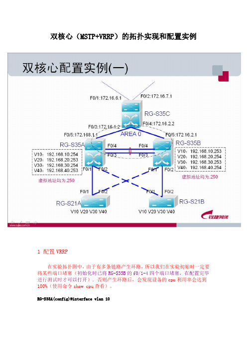
双核心(MSTP+VRRP)的拓扑实现和配置实例1 配置VRRP在实验拓扑图中,由于有多条链路产生环路,所以我们在实验初始时一定要将某些端口堵塞(初始化时已将RG-S35B的f0/1-4四个端口堵塞,在配置完毕进行测试时才可以打开).否则产生环路后,会发现设备的cpu利用率会达到100%(使用命令show cpu查看)。
RG-S35A(config)#interface vlan 10RG-S35A(config-if)#ip address 192.168.10.254 255.255.255.0 !配置VLAN10的IP 地址RG-S35A(config-if)#standby 1 ip 192.168.10.250 !配置虚拟IPRG-S35A(config-if)#standby 1 preempt!设为抢占模式RG-S35A(config-if)#standby 1 priority 254 !VLAN10的standby优先级设为254RG-S35A(config-if)#exitRG-S35A(config)#interface vlan 20 !VLAN20的standby不设优先级,默认为100RG-S35A(config-if)#ip address 192.168.20.253 255.255.255.0 !配置VLAN20的IP 地址RG-S35A(config-if)#standby 2 ip 192.168.20.250 !配置虚拟IPRG-S35A(config-if)#standby 2 preempt !设为抢占模式RG-S35A(config-if)#exitRG-S35A(config)#interface vlan 30RG-S35A(config-if)#ip address 192.168.30.254 255.255.255.0 !配置VLAN30的IP 地址RG-S35A(config-if)#standby 3 ip 192.168.30.250 !配置虚拟IPRG-S35A(config-if)#standby 3 preempt !设为抢占模式RG-S35A(config-if)#standby 3 priority 254 !VLAN30的standby优先级设为254RG-S35A(config-if)#exitRG-S35A(config)#interface vlan 40 !VLAN20的standby不设优先级,默认为100RG-S35A(config-if)#ip address 192.168.40.253 255.255.255.0 !配置VLAN40的IP 地址RG-S35A(config-if)#standby 4 ip 192.168.40.250 !配置虚拟IPRG-S35A(config-if)#stand 4 preempt !设为抢占模式RG-S35A(config-if)#exitRG-S35A(config)#exitRG-S35B把vlan20 40 设置为standby 2、4 priority 2542 配置RG-S35A与RG-S35B的端口聚合理论上,35A和35B的f0/3和f0/4端口不需要设置为trunk口,但是我们习惯上都设为trunk(已在前面做好了配置)。
怎么在交换机上配置VRRP、arp和MSTP

全是锐捷的命令采用生成树协议只能做到链路级备份,无法做到网关级备份.MSTP与VRRP结合可以同时做到链路备份与网关级备份,极大地提高了网络的健壮性.配置要求:vlan 10以SW1为根桥,并且相应的VRRP Master也在SW1上, vlan 20以SW2为根桥,并且相应的VRRP Master也在SW2上。
配置VRRP+MSTP的重要原则是:在进行MSTP和VRRP结合配置使用时,需要注意的就是保持各VLAN的根桥与各自的VRRP Master需要保持在同一台三层交换机上。
SW1相关配置spanning-treespanning-tree mst configurationinstance 1 vlan 10instance 2 vlan 20name testrevision 1!spanning-tree mst 0 priority 4096 (设置SW1的实例1优先级最高,手动指定实例1的根桥为SW1)spanning-tree mst 1 priority 4096 (设置SW1的实例1优先级最高,手动指定实例1的根桥为SW1)spanning-tree mst 2 priority 8192interface FastEthernet 0/1switchport mode trunkinterface FastEthernet 0/2switchport mode trunkinterface Vlan 10(设置SW1上VLAN10的VRRP的优先级为150,高于默认的100-SW2上的VLAN10的VRRP优先级为100)ip address 192.168.10.2 255.255.255.0standby 10 ip 192.168.10.1standby 10 priority 150!interface Vlan 20ip address 192.168.20.3 255.255.255.0standby 20 ip 192.168.20.1SW2相关配置spanning-treespanning-tree mst configurationinstance 1 vlan 10instance 2 vlan 20name testrevision 1!spanning-tree mst 0 priority 8192spanning-tree mst 1 priority 8192spanning-tree mst 2 priority 4096 (设置SW1的实例1优先级最高,手动指定实例1的根桥为SW1)interface FastEthernet 0/1switchport mode trunkinterface FastEthernet 0/2switchport mode trunkinterface Vlan 10ip address 192.168.10.3 255.255.255.0standby 10 ip 192.168.10.1!interface Vlan 20(设置SW1上VLAN10的VRRP的优先级为150,高于默认的100)ip address 192.168.20.2 255.255.255.0standby 20 ip 192.168.20.1standby 20 priority 150SW3相关配置spanning-treespanning-tree mst configurationinstance 1 vlan 10instance 2 vlan 20name testrevision 1!interface fastEthernet 0/1switchport mode trunkinterface fastEthernet 0/2switchport mode trunkVRRP协议状态检查SW1#sh standbyIf Group State Priority Preempt Interval Virtual IP Auth ------- ----- ------ -------- ------- -------- --------------- -------- VL10 10 master 150 may 1 192.168.10.1VL20 20 backup 100 may 1 192.168.20.1SW2#sh standbyIf Group State Priority Preempt Interval Virtual IP Auth ------- ----- ------ -------- ------- -------- --------------- -------- VL10 10 backup 100 may 1 192.168.10.1VL20 20 master 150 may 1 192.168.20.1生成树协议状态检查实例1的根桥在SW1上,实例2的根桥在SW2上。
校园网双核心(MSTP+VRRP)的拓扑实现和配置实例

双核心配置实例(一)cont.
RG-S35A(config)#spanning-tree mst 1 priority 4096
!实例1在35A的优先级为4096
RG-S35A(config)#spanning-tree mst 2 priority 8192
!实例2在35A的优先级为8192
配置较高优先级是为了使35A被选作mst 1的根节点。一 方面是因为它的性能比21强,防止21被选做根节点;更 重要的是,如果默认优先级更高的为35B,则vlan10、 30也会通过35B传输,与我们的期望结果相违背,产生 冲突。
MSTP技术概述(cont.)
交换机A、B 在vlan1 内,交换机C、D 在vlan2 内,连成环路。
A vlan1 C vlan2
vlan1 B D
vlan2
MSTP技术概述(cont.)
若采用STP或RSTP,在某种配置下,会把交换机A和B 间的链路给discarding。
A vlan1 C vlan2
OA服务器 服务器VLAN 服务器 视频会议VLAN 视频会议 交换机管理VLAN 交换机管理 互连网段VLAN 互连网段
双核心配置实例(二)cont.
生成树协议管理
表二、 表二、 设备优先级列表 设备 主核心交换机 备核心交换机 接入交换机 优先级 4096 8192 默认32768 默认
双核心配置实例(二)cont.
接入交换机 RG-S2150G
双核心配置实例(二)cont.
VLAN规划
根据支行的网络应用情况,针对不同的业务系统进行VLAN部 署整理,如下表:
表一
用途 生产用户VLAN 生产用户 OA用户 用户VLAN 用户
VRRP+MSTP配置
VRRP+MSTP配置VRRP+MSTP(多实例⽣成树+双路由冗余)实现负载分担MSTP (多⽣成树) 每个VLAN或者⼏个VLAN拥有⼀颗⽣成树,基于实例的⽣成树。
instance 1、instance 2 每个实例拥有⼀颗⽣成树。
MSTP可以实现多VLAN 的负载分担,可以实现多⼚商对接。
VRRP虚拟路由冗余协议(Virtual Router Redundancy Protocol)是由IETF提出的解决局域⽹中配置静态⽹关出现单点失效现象的路由协议。
拓扑如下:交换机与交换机之间的链路为trunk类型,放⾏vlan10 20SW1配置:[sw1]vlan batch 10 20 #创建vlan10 20[sw1-Vlanif10]dis this#interface Vlanif10ip address 192.168.10.1 255.255.255.0 #配置物理⽹关地址vrrp vrid 1 virtual-ip 192.168.10.254 #配置vrrp组1 配置虚拟⽹关地址vrrp vrid 1 priority 120 #配置优先级为120,默认100数字越⼤越优先,使它成为vlan10的Mastervrrp vrid 1 track interface GigabitEthernet0/0/3 reduced 30 #检测上联端⼝,如果断开优先级降低30(之后会作为backup)#[sw1-Vlanif20]dis this#interface Vlanif20ip address 192.168.20.1 255.255.255.0 #配置vlan20的物理⽹关vrrp vrid 2 virtual-ip 192.168.20.254 #配置vlan20的虚拟⽹关vrrp vrid 2 preempt-mode timer delay 20 #延迟20秒后抢占MSTP配置[sw1]stp mode mstp #配置stp模式为mstp[sw1]stp region-configuration #进⼊stp配置模式[sw1-mst-region]dis this#stp region-configurationregion-name HW #配置域名为HWrevision-level 1 #配置版本等级为1(可选)instance 10 vlan 10 #配置vlan10 加⼊实例10instance 20 vlan 20 #配置vlan20 加⼊实例20active region-configuration#[sw1]stp instance 10 root primary #配置实例10为根[sw1]stp instance 20 root secondary #配置实例20为备份根SW2配置:[sw2]vlan batch 10 20[sw2-Vlanif10]dis this#interface Vlanif10ip address 192.168.10.2 255.255.255.0 #配置vlan10⽹关vrrp vrid 1 virtual-ip 192.168.10.254 #配置vrrp组1 配置虚拟⽹关和SW1⼀样vrrp vrid 1 preempt-mode timer delay 20 #延迟20s后抢占#[sw2-Vlanif20]dis this#interface Vlanif20ip address 192.168.20.2 255.255.255.0 #配置vlan20⽹关vrrp vrid 2 virtual-ip 192.168.20.254 #配置vrrp组2 配置虚拟⽹关和SW1⼀样vrrp vrid 2 priority 120 #配置优先级为120,使vrrp2 成为vlan20的Mastervrrp vrid 2 track interface GigabitEthernet0/0/22 reduced 30 #配置上联链路检测,如果断开优先级减去30 使它成为backup#MSTP配置[sw2]stp mode mstp #配置stp模式为mstp[sw2]stp region-configuration #进⼊stp配置模式[sw2-mst-region]dis this#stp region-configurationregion-name HW #配置域名为HWrevision-level 1 #配置版本等级为1(可选)instance 10 vlan 10 #配置vlan10 加⼊实例10instance 20 vlan 20 #配置vlan20 加⼊实例20active region-configuration#[sw2]stp instance 20 root primary #配置实例20为根[sw2]stp instance 10 root secondary #配置实例10为备份根SW3配置:[sw3]vlan batch 10 20MSTP配置[sw3]stp mode mstp #配置stp模式为mstp[sw3]stp region-configuration #进⼊stp配置模式[sw3-mst-region]dis this#stp region-configurationregion-name HW #配置域名为HWrevision-level 1 #配置版本等级为1(可选)instance 10 vlan 10 #配置vlan10 加⼊实例10instance 20 vlan 20 #配置vlan20 加⼊实例20active region-configuration#SW4配置:[sw4]vlan batch 10 20MSTP配置[sw4]stp mode mstp #配置stp模式为mstp[sw4]stp region-configuration #进⼊stp配置模式[sw4-mst-region]dis this#stp region-configurationregion-name HW #配置域名为HWrevision-level 1 #配置版本等级为1(可选)instance 10 vlan 10 #配置vlan10 加⼊实例10instance 20 vlan 20 #配置vlan20 加⼊实例20active region-configuration#测试效果:可以看出来PC3⾛的是 sw1的⽹关PC4⾛的是SW2的⽹关假设SW1的上联链路断开:SW2接管了vlan10成为了Master<sw2>dis vrrpVlanif10 | Virtual Router 10State : Master #sw2变成了vlan10的Master Virtual IP : 192.168.10.254Master IP : 192.168.10.2PriorityRun : 100PriorityConfig : 100MasterPriority : 100Preempt : YES Delay Time : 20 sTimerRun : 1 sTimerConfig : 1 sAuth type : NONEVirtual MAC : 0000-5e00-010aCheck TTL : YESConfig type : normal-vrrpCreate time : 2021-09-0720:41:05 UTC-08:00Last change time : 2021-09-0810:39:48 UTC-08:00可以看出来PC3的数据从SW1切换到了SW2上End。
怎样配置VRRP+MSTP

VRRP+MSTP实验拓扑图SWASWB SW3Vlan 10,20Vlan 10,20 1 1 链路聚合 2 2 23-2423-24 Vlan 10,20 Vlan 10 ip:192.168.10.252 虚拟网关地址:192.168.10.254 Vlan 20 ip:192.168.20.252 虚拟网关地址:192.168.20.254 Vlan 10 ip:192.168.10.253虚拟网关地址:192.168.10.254Vlan 20 ip:192.168.20.253虚拟网关地址:192.168.20.254Vlan 10 用户网关地址:192.168.10.254Vlan 20 用户网关地址:192.168.20.254要求vlan10的用户流量在SWA 上,vlan 20的用户流量在SWB 上VRRP 配置SWA 的配置SWA(config)#interface Vlan 10(设置SWA 上VLAN10的VRRP 的优先级为150,高于默认的100-SWB 上的VLAN10的VRRP 优先级为100)SWA(config-if)#ip address 192.168.10.253 255.255.255.0SWA(config-if)#vrrp 10 ip 192.169.10.254SWA(config-if)#vrrp 10 priority 150SWA(config-if)#exitSWA(config)#interface Vlan 20SWA(config-if)#ip address 192.168.20.253 255.255.255.0SWA(config-if)#vrrp 20 ip 192.168.20.254VRRP配置(续)SWB的配置SWB(config)#interface Vlan 10SWB(config-if)#ip address 192.168.10.252 255.255.255.0SWB(config-if)#vrrp 10 ip 192.169.10.254SWB(config-if)#exitSWB(config)#interface Vlan 20SWB(config-if)#ip address 192.168.20.252 255.255.255.0SWB(config-if)#vrrp 20 ip 192.168.20.254(设置SWA上VLAN20的VRRP的优先级为150,高于默认的100-SWB 上的VLAN20的VRRP优先级为100)SWB(config-if)#vrrp 20 priority 150交换机上配置VRRP提问:怎么配置VRRP回答:步骤一:Master:ruijie(config)#track 1 interface f0/0 ---端口追踪ruijie(config)#interface Vlan 10ruijie(config-if)#ip addr 10.10.10.1 255.255.255.0ruijie(config-if)#vrrp 1 priority 120 ---设置优先级,默认100,优先级高的成为主ruijie(config-if)#vrrp 1 ip 10.10.10.10 ---配置虚拟网关ruijie(config-if)#vrrp 1 timer advertise 3 ---调定时器,可选ruijie(config-if)#vrrp 1 preempt ---配抢占ruijie(config-if)#vrrp 1 track 1 100 ---追踪端口优先级降低值步骤二:Backup:ruijie(config)#interface Vlan 10ruijie(config-if)#ip addr 10.10.10.2 255.255.255.0ruijie(config-if)#vrrp 1 priority 100 ---设置优先级,默认100ruijie(config-if)#vrrp 1 ip 10.10.10.10ruijie(config-if)#vrrp 1 timer advertise 3 ---调定时器,可选ruijie(config-if)#vrrp 1 preempt ---配抢占验证:验证结果show vrrp [brief]show vrrp interface 接口show track小结:简单来说 VRRP 是一种容错协议 它为具有组播或广播能力的局域网 如以太网 设计 它保证当局域网内主机的下一跳路由器出现故障时 可以及时的由另一台路由器来代替 从而保持通讯的连续性和可靠性 为了使VRRP 工作 要在路由器上配置虚拟路由器号和虚拟IP 地址 同时产生一个虚拟MAC 地址 这样在这个网络中就加入了一个虚拟路由器 而网络上的主机与虚拟路由器通信 无需了解这个网络上物理路由器的任何信息 一个虚拟路由器由一个主路由器和若干个备份路由器组成 主路由器实现真正的转发功能 当主路由器出现故障时 一个备份路由器将成为新的主路由器 接替它的工作。
双核心VRRP+mstp配置
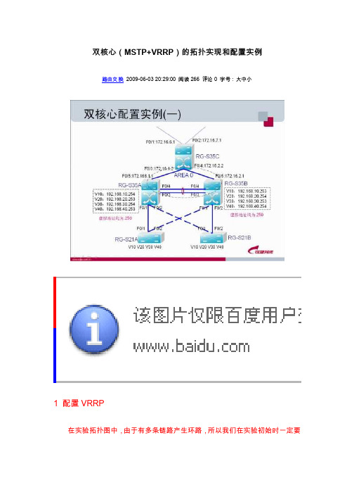
ĉ MSTP+VRRP ጱ෪" Ǐď?3 Ý2009-06-03 20:29:00 266 01 ?3VRRP෪"Ī /Óྞ 'ʦɟࡘ/Ǐɟ "ࡾ"Ù ༭ÐÔ ੰ ༭ఉ RG-S35Bጱf0/1-4Ĩ ੰ ?3 ɲ ༭"ċࡾ"ľ ࡘ/Ǐɟč Ǐ ጱcpu /ለ ɰ 100% Ü/Ďࡽshow cpu dzRG-S35A(config-if)#ip address 192.168.10.254 255.255.255.0RG-S35A(config-if)#standby 1 ip 192.168.10.250RG-S35A(config-if)#standby 1 preemptRG-S35A(config-if)#standby 1 priority 254RG-S35A(config-if)#exitRG-S35A(config)#interface vlan 20RG-S35A(config-if)#ip address 192.168.20.253 255.255.255.0RG-S35A(config-if)#standby 2 ip 192.168.20.250RG-S35A(config-if)#standby 2 preemptRG-S35A(config-if)#exitRG-S35A(config)#interface vlan 30RG-S35A(config-if)#ip address 192.168.30.254 255.255.255.0RG-S35A(config-if)#standby 3 ip 192.168.30.250RG-S35A(config-if)#standby 3 preemptRG-S35A(config-if)#standby 3 priority 254RG-S35A(config-if)#exitRG-S35A(config)#interface vlan 40RG-S35A(config-if)#ip address 192.168.40.253 255.255.255.0RG-S35A(config-if)#standby 4 ip 192.168.40.250RG-S35A(config-if)#stand 4 preemptRG-S35A(config-if)#exitRG-S35A(config)#exitRG-S35B vlan20 40 standby 2 4 priority 2542 ?35* 6 $Ñ5* 6 %ጱ ੰ4ઉ ࠳ $ď %ጱI ďI ੰÑʺ 3 WUXQNੰ &"Ù ő࠳ɾ WUXQN ఉ E ࡃ?3ʅჼ Ð DJJUHJDWH3RUWጱVZLWFKSRUW PRGH?3 WUXQN Ŀ ॥᯿ DFFHVV ĿRG-S35A(config-if)#port-group 1RG-S35A(config-if)#exitRG-S35A(config)#interface f0/4RG-S35A(config-if)#port-group 1RG-S35A(config-if)#endRG-S35A(config)#interface aggregatePort 1RG-S35A(config-if)#switchport mode trunkRG-S35A(config-if)#exitRG-S35BRG-S35B(config)#interface f0/3RG-S35B(config-if)#no shutdownRG-S35B(config-if)#interface f0/4RG-S35B(config-if)#no shutdownRG-S35B(config-if)#exit35BRG-S35A(config)#interface vlan 20RG-S35A(config-if)#ip ospf cost 65535RG-S35A(config-if)#exitRG-S35A(config)#interface vlan 40RG-S35A(config-if)#ip ospf cost 65535RG-S35A(config-if)#exitRG-S35BRG-S35B(config)#interface vlan 10 RG-S35B(config-if)#ip ospf cost 65535RG-S35B(config-if)#exitRG-S35B(config)#interface vlan 30 RG-S35B(config-if)#ip ospf cost 65535RG-S35B(config-if)#exit3 ?30673RG-S21A(config)#spanning-tree mode mstpRG-S21A(config)#spanning-tree mst configurationRG-S21A(config-mst)#instance 1 VLAN 10,30RG-S21A(config-mst)#revision 1RG-S21A(config-mst)#instance 2 vlan 20,40RG-S21A(config-mst)#revision 1RG-S21A(config-mst)#exitRG-S21BRG-S35ARG-S35A(config)#spanning-tree mst 1 priority 4096RG-S35A(config)#spanning-tree mst 2 priority 81921RG-S35BRG-S35B(config)#spanning-tree mst 2 priority 4096RG-S35B(config)#spanning-tree mst 1 priority 8192 RG-S35B(config)#interface range fastEthernet 0/1-2RG-S35B(config-if-range)#no shutdown4RG-S35A#show ip routeRG-S35B#show standbyRG-S35B#show ip routeVLAN103035A,VLAN204035B,standbyRG-S35C#show ip route。
思科交换机+vrrp+mstp配置实例
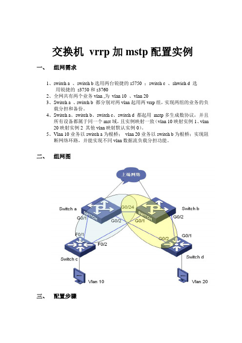
交换机vrrp加mstp配置实例一、组网需求1、switch a 、switch b选用两台锐捷的s5750 ;switch c 、shwich d 选用锐捷的s3750和s37602、全网共有两个业务vlan ,为vlan 10 、vlan 203、Switch a 、switch b 都分别对两vlan起用两vrrp组,实现两组的业务的负载分担和备份。
4、Switch a、switch b、switch c、switch d 都起用mstp多生成数协议,并且所有设备都属于同一个mst域,且实例映射一致(vlan 10映射实例1、vlan 20映射实例2 其他vlan映射默认实例0)。
5、Vlan 10业务以switch a为根桥;vlan 20业务以switch b为根桥;实现阻断网络环路,并能实现不同vlan数据流负载分担功能。
二、组网图三、配置步骤Switch a配置:s1#show runBuilding configuration...Current configuration : 1651 bytes!version RGNOS 10.2.00(2), Release(29287)(Tue Dec 25 20:39:14 CST 2007 -ngcf49) hostname s1co-operate enable!!!vlan 1!vlan 10!vlan 20!!no service password-encryption!spanning-tree 开启生成树(默认为mstp)spanning-tree mst configuration 进入mst配置模式revision 1 指定MST revision number 为1name region1 指定mst配置名称instance 0 vlan 1-9, 11-19, 21-4094 缺省情况下vlan都属于实例0instance 1 vlan 10 手工指定vlan10属于实例1instance 2 vlan 20 手工指定vlan20属于实例2spanning-tree mst 1 priority 0 指定实例1的优先级为0(为根桥)spanning-tree mst 2 priority 4096 指定实例2的优先级为4096interface GigabitEthernet 0/1switchport access vlan 10 配置g0/1属于vlan10!interface GigabitEthernet 0/2switchport access vlan 20 配置g0/2属于vlan 20!interface GigabitEthernet 0/3!..interface GigabitEthernet 0/24 设置g0/24为trunk接口且允许vlan10/20通过switchport mode trunk!interface VLAN 10 创建vlan 10 svi接口ip address 192.168.10.1 255.255.255.0 配置ip地址vrrp 1 priority 120 配置vrrp组1 优先级为120vrrp 1 ip 192.168.10.254 配置vrrp组1虚拟ip地址为192.168.10.254!interface VLAN 20 创建vlan 20 svi接口ip address 192.168.20.1 255.255.255.0 配置ip地址vrrp 2 ip 192.168.20.254 配置vrrp组2虚拟ip地址为192.168.20.254默认vrrp组的优先级为100默认不显示!line con 0line vty 0 4logins1#show vlanVLAN Name Status Ports---- -------------------------------- --------- ----------------------------------1 VLAN0001 STATIC Gi0/3, Gi0/4, Gi0/5, Gi0/6Gi0/7, Gi0/8, Gi0/9, Gi0/10Gi0/11, Gi0/12, Gi0/13, Gi0/14Gi0/15, Gi0/16, Gi0/17, Gi0/18Gi0/19, Gi0/20, Gi0/21, Gi0/22Gi0/23, Gi0/2410 VLAN0010 STATIC Gi0/1, Gi0/2420 VLAN0020 STATIC Gi0/2, Gi0/24Switch b配置:s2#show runBuilding configuration...Current configuration : 1607 bytes!version RGNOS 10.2.00(2), Release(27932)(Thu Dec 13 10:32:09 CST 2007 -ngcf31) hostname s2!!!vlan 1!vlan 10!vlan 20!!no service password-encryption!spanning-treespanning-tree mst configurationrevision 1name region1instance 0 vlan 1-9, 11-19, 21-4094instance 1 vlan 10instance 2 vlan 20spanning-tree mst 1 priority 4096spanning-tree mst 2 priority 0interface GigabitEthernet 0/1switchport access vlan 10!interface GigabitEthernet 0/2switchport access vlan 20!..interface GigabitEthernet 0/24switchport mode trunk!interface VLAN 10ip address 192.168.10.2 255.255.255.0vrrp 1 ip 192.168.10.254!interface VLAN 20ip address 192.168.20.2 255.255.255.0vrrp 2 priority 120vrrp 2 ip 192.168.20.254!line con 0line vty 0 4login!!ends2#show vlanVLAN Name Status Ports---- -------------------------------- --------- -----------------------------------1 VLAN0001 STATIC Gi0/3, Gi0/4, Gi0/5, Gi0/6Gi0/7, Gi0/8, Gi0/9, Gi0/10Gi0/11, Gi0/12, Gi0/13, Gi0/14Gi0/15, Gi0/16, Gi0/17, Gi0/18Gi0/19, Gi0/20, Gi0/21, Gi0/22Gi0/23, Gi0/2410 VLAN0010 STATIC Gi0/1, Gi0/2420 VLAN0020 STATIC Gi0/2, Gi0/24Switch c配置:s3#show runBuilding configuration...Current configuration : 1540 bytes!version RGNOS 10.2.00(2), Release(28794)(Fri Dec 21 09:27:15 CST 2007 -ngcf32) hostname s3!vlan 1!vlan 10!!service password-encryption!spanning-treespanning-tree mst configurationrevision 1name region1instance 0 vlan 1-9, 11-19, 21-4094instance 1 vlan 10instance 2 vlan 20spanning-tree mst 1 priority 0spanning-tree mst 2 priority 4096interface FastEthernet 0/1switchport access vlan 10!interface FastEthernet 0/2switchport access vlan 10!..interface GigabitEthernet 0/25!interface GigabitEthernet 0/26!interface GigabitEthernet 0/27!interface GigabitEthernet 0/28!interface VLAN 10ip address 192.168.10.3 255.255.255.0!ip route 0.0.0.0 0.0.0.0 192.168.10.254!!line con 0line vty 0 4loginSwitch d配置:s4#show runBuilding configuration...Current configuration : 1066 bytes!version RGNOS 10.2.00(2), Release(27932)(Thu Dec 13 10:31:41 CST 2007 -ngcf32) hostname s4!vlan 1!vlan 20!!no service password-encryption!spanning-treespanning-tree mst configurationrevision 1name region1instance 0 vlan 1-9, 11-19, 21-4094instance 1 vlan 10instance 2 vlan 20spanning-tree mst 1 priority 4096spanning-tree mst 2 priority 0interface GigabitEthernet 0/1switchport access vlan 20!interface GigabitEthernet 0/2switchport access vlan 20!..interface GigabitEthernet 0/12!interface VLAN 20ip address 192.168.20.3 255.255.255.0!!!!ip route 0.0.0.0 0.0.0.0 192.168.20.254!!line con 0line vty 0 4login!四、查看vrrp、mstp信息Switch a 信息:s1#show vrrp 查看vrrp 信息VLAN 10 - Group 1State is MasterVirtual IP address is 192.168.10.254 configuredVirtual MAC address is 0000.5e00.0101Advertisement interval is 1 secPreemption is enabledmin delay is 0 secPriority is 120Master Router is 192.168.10.1 (local), priority is 120Master Advertisement interval is 1 secMaster Down interval is 3 secVLAN 20 - Group 2State is BackupVirtual IP address is 192.168.20.254 configuredVirtual MAC address is 0000.5e00.0102Advertisement interval is 1 secPreemption is enabledmin delay is 0 secPriority is 100Master Router is 192.168.20.2 , priority is 120Master Advertisement interval is 1 secMaster Down interval is 3 secs1#s1#s1#s1#show spanning-tree interface gigabitEthernet 0/1 查看g0/1接口stp状态信息PortAdminPortFast : Disabled PortOperPortFast : Disabled PortAdminAutoEdge : Enabled PortOperAutoEdge : Disabled PortAdminLinkType : auto PortOperLinkType : point-to-point PortBPDUGuard : DisabledPortBPDUFilter : Disabled###### MST 0 vlans mapped :1-9, 11-19, 21-4094 PortState : forwardingPortPriority : 128PortDesignatedRoot : 8000.001a.a909.8fe0 PortDesignatedCost : 0 PortDesignatedBridge :8000.00d0.f836.ed70 PortDesignatedPort : 8001 PortForwardTransitions : 6 PortAdminPathCost : 200000 PortOperPathCost : 200000PortRole : designatedPort###### MST 1 vlans mapped :10PortState : forwardingPortPriority : 128PortDesignatedRoot : 0001.00d0.f823.ef82 PortDesignatedCost : 0 PortDesignatedBridge :0001.00d0.f823.ef82 PortDesignatedPort : 8001 PortForwardTransitions : 5 PortAdminPathCost : 200000 PortOperPathCost : 200000PortRole : rootPort###### MST 2 vlans mapped :20PortState : forwardingPortPriority : 128PortDesignatedRoot : 0002.001a.a909.8fe0 PortDesignatedCost : 0 PortDesignatedBridge :1002.00d0.f836.ed70 PortDesignatedPort : 8001 PortForwardTransitions : 4 PortAdminPathCost : 200000 PortOperPathCost : 200000PortRole : designatedPorts1#s1#s1#show spanning-tree interface gigabitEthernet 0/2 查看g0/2接口stp状态信息PortAdminPortFast : DisabledPortOperPortFast : DisabledPortAdminAutoEdge : EnabledPortOperAutoEdge : DisabledPortAdminLinkType : autoPortOperLinkType : point-to-pointPortBPDUGuard : DisabledPortBPDUFilter : Disabled###### MST 0 vlans mapped :1-9, 11-19, 21-4094PortState : forwardingPortPriority : 128PortDesignatedRoot : 8000.001a.a909.8fe0PortDesignatedCost : 0PortDesignatedBridge :8000.00d0.f836.ed70PortDesignatedPort : 8002PortForwardTransitions : 5PortAdminPathCost : 20000PortOperPathCost : 20000PortRole : designatedPort###### MST 1 vlans mapped :10PortState : forwardingPortPriority : 128PortDesignatedRoot : 0001.00d0.f823.ef82PortDesignatedCost : 0PortDesignatedBridge :0001.00d0.f836.ed70PortDesignatedPort : 8002PortForwardTransitions : 4PortAdminPathCost : 20000PortOperPathCost : 20000PortRole : designatedPort###### MST 2 vlans mapped :20PortState : discardingPortPriority : 128PortDesignatedRoot : 0002.001a.a909.8fe0PortDesignatedCost : 0PortDesignatedBridge :0002.00d0.f8d7.ae12PortDesignatedPort : 8002PortForwardTransitions : 3PortAdminPathCost : 20000PortOperPathCost : 20000PortRole : alternatePorts1#s1#s1#show spanning-tree interface gigabitEthernet 0/24 g0/24接口stp状态信息PortAdminPortFast : DisabledPortOperPortFast : DisabledPortAdminAutoEdge : EnabledPortOperAutoEdge : DisabledPortAdminLinkType : autoPortOperLinkType : point-to-pointPortBPDUGuard : DisabledPortBPDUFilter : Disabled###### MST 0 vlans mapped :1-9, 11-19, 21-4094PortState : forwardingPortPriority : 128PortDesignatedRoot : 8000.001a.a909.8fe0PortDesignatedCost : 0PortDesignatedBridge :8000.001a.a909.8fe0PortDesignatedPort : 8018PortForwardTransitions : 5PortAdminPathCost : 20000PortOperPathCost : 20000PortRole : rootPort###### MST 1 vlans mapped :10PortState : forwardingPortPriority : 128PortDesignatedRoot : 0001.00d0.f823.ef82PortDesignatedCost : 0PortDesignatedBridge :0001.00d0.f836.ed70PortDesignatedPort : 8018PortForwardTransitions : 5PortAdminPathCost : 20000PortOperPathCost : 20000PortRole : designatedPort###### MST 2 vlans mapped :20PortState : forwardingPortPriority : 128PortDesignatedRoot : 0002.001a.a909.8fe0 PortDesignatedCost : 0PortDesignatedBridge :0002.001a.a909.8fe0 PortDesignatedPort : 8018 PortForwardTransitions : 4PortAdminPathCost : 20000PortOperPathCost : 20000PortRole : rootPorts1#Switch b 信息:s2#show vrrpVLAN 10 - Group 1State is BackupVirtual IP address is 192.168.10.254 configured Virtual MAC address is 0000.5e00.0101 Advertisement interval is 1 secPreemption is enabledmin delay is 0 secPriority is 100Master Router is 192.168.10.1 , priority is 120 Master Advertisement interval is 1 secMaster Down interval is 3 secVLAN 20 - Group 2State is MasterVirtual IP address is 192.168.20.254 configured Virtual MAC address is 0000.5e00.0102 Advertisement interval is 1 secPreemption is enabledmin delay is 0 secPriority is 120Master Router is 192.168.20.2 (local), priority is 120 Master Advertisement interval is 1 secMaster Down interval is 3 secs2#s2#s2#s2#s2#s2#s2#show spanning-tree interface gigabitEthernet 0/1PortAdminPortFast : Disabled PortOperPortFast : Disabled PortAdminAutoEdge : Enabled PortOperAutoEdge : Disabled PortAdminLinkType : auto PortOperLinkType : point-to-point PortBPDUGuard : DisabledPortBPDUFilter : Disabled###### MST 0 vlans mapped :1-9, 11-19, 21-4094 PortState : forwardingPortPriority : 128PortDesignatedRoot : 8000.001a.a909.8fe0 PortDesignatedCost : 0 PortDesignatedBridge :8000.001a.a909.8fe0 PortDesignatedPort : 8001 PortForwardTransitions : 1 PortAdminPathCost : 200000 PortOperPathCost : 200000PortRole : designatedPort###### MST 1 vlans mapped :10PortState : forwardingPortPriority : 128PortDesignatedRoot : 0001.00d0.f823.ef82 PortDesignatedCost : 0 PortDesignatedBridge :0001.00d0.f823.ef82 PortDesignatedPort : 8002 PortForwardTransitions : 2 PortAdminPathCost : 200000 PortOperPathCost : 200000PortRole : rootPort###### MST 2 vlans mapped :20PortState : forwardingPortPriority : 128PortDesignatedRoot : 0002.001a.a909.8fe0 PortDesignatedCost : 0 PortDesignatedBridge :0002.001a.a909.8fe0 PortDesignatedPort : 8001 PortForwardTransitions : 1 PortAdminPathCost : 200000 PortOperPathCost : 200000PortRole : designatedPorts2#s2#s2#s2#show spanning-tree interface gigabitEthernet 0/2 PortAdminPortFast : Disabled PortOperPortFast : Disabled PortAdminAutoEdge : Enabled PortOperAutoEdge : Disabled PortAdminLinkType : autoPortOperLinkType : point-to-point PortBPDUGuard : DisabledPortBPDUFilter : Disabled###### MST 0 vlans mapped :1-9, 11-19, 21-4094 PortState : forwardingPortPriority : 128PortDesignatedRoot : 8000.001a.a909.8fe0 PortDesignatedCost : 0 PortDesignatedBridge :8000.001a.a909.8fe0 PortDesignatedPort : 8002 PortForwardTransitions : 1 PortAdminPathCost : 20000 PortOperPathCost : 20000PortRole : designatedPort###### MST 1 vlans mapped :10PortState : forwardingPortPriority : 128PortDesignatedRoot : 0001.00d0.f823.ef82 PortDesignatedCost : 0 PortDesignatedBridge :1001.001a.a909.8fe0 PortDesignatedPort : 8002 PortForwardTransitions : 2 PortAdminPathCost : 20000 PortOperPathCost : 20000PortRole : designatedPort###### MST 2 vlans mapped :20PortState : forwardingPortPriority : 128PortDesignatedRoot : 0002.001a.a909.8fe0 PortDesignatedCost : 0PortDesignatedBridge :0002.001a.a909.8fe0 PortDesignatedPort : 8002 PortForwardTransitions : 1PortAdminPathCost : 20000PortOperPathCost : 20000PortRole : designatedPorts2#s2#s2#s2#s2#show spanning-tree interface gigabitEthernet 0/24 PortAdminPortFast : Disabled PortOperPortFast : Disabled PortAdminAutoEdge : Enabled PortOperAutoEdge : Disabled PortAdminLinkType : autoPortOperLinkType : point-to-point PortBPDUGuard : DisabledPortBPDUFilter : Disabled###### MST 0 vlans mapped :1-9, 11-19, 21-4094 PortState : forwardingPortPriority : 128PortDesignatedRoot : 8000.001a.a909.8fe0 PortDesignatedCost : 0PortDesignatedBridge :8000.001a.a909.8fe0 PortDesignatedPort : 8018 PortForwardTransitions : 1PortAdminPathCost : 20000PortOperPathCost : 20000PortRole : designatedPort###### MST 1 vlans mapped :10PortState : discardingPortPriority : 128PortDesignatedRoot : 0001.00d0.f823.ef82 PortDesignatedCost : 0PortDesignatedBridge :0001.00d0.f836.ed70 PortDesignatedPort : 8018 PortForwardTransitions : 1PortAdminPathCost : 20000PortOperPathCost : 20000PortRole : alternatePort###### MST 2 vlans mapped :20PortState : forwardingPortPriority : 128PortDesignatedRoot : 0002.001a.a909.8fe0 PortDesignatedCost : 0 PortDesignatedBridge :0002.001a.a909.8fe0 PortDesignatedPort : 8018 PortForwardTransitions : 1 PortAdminPathCost : 20000 PortOperPathCost : 20000PortRole : designatedPorts2#Switch c 信息:s3#show spanning-tree interface fastEthernet 0/1 PortAdminPortFast : Disabled PortOperPortFast : Disabled PortAdminAutoEdge : Enabled PortOperAutoEdge : Disabled PortAdminLinkType : auto PortOperLinkType : point-to-point PortBPDUGuard : DisabledPortBPDUFilter : Disabled###### MST 0 vlans mapped :1-9, 11-19, 21-4094 PortState : discardingPortPriority : 128PortDesignatedRoot : 8000.001a.a909.8fe0 PortDesignatedCost : 0 PortDesignatedBridge :8000.00d0.f836.ed70 PortDesignatedPort : 8001 PortForwardTransitions : 1 PortAdminPathCost : 200000 PortOperPathCost : 200000PortRole : alternatePort###### MST 1 vlans mapped :10PortState : forwardingPortPriority : 128PortDesignatedRoot : 0001.00d0.f823.ef82PortDesignatedCost : 0 PortDesignatedBridge :0001.00d0.f823.ef82 PortDesignatedPort : 8001 PortForwardTransitions : 1 PortAdminPathCost : 200000 PortOperPathCost : 200000PortRole : designatedPort###### MST 2 vlans mapped :20PortState : discardingPortPriority : 128PortDesignatedRoot : 0002.001a.a909.8fe0 PortDesignatedCost : 0 PortDesignatedBridge :1002.00d0.f836.ed70 PortDesignatedPort : 8001 PortForwardTransitions : 0 PortAdminPathCost : 200000 PortOperPathCost : 200000PortRole : alternatePorts3#s3#s3#s3#s3#show spanning-tree interface fastEthernet 0/2 PortAdminPortFast : Disabled PortOperPortFast : Disabled PortAdminAutoEdge : Enabled PortOperAutoEdge : Disabled PortAdminLinkType : auto PortOperLinkType : point-to-point PortBPDUGuard : DisabledPortBPDUFilter : Disabled###### MST 0 vlans mapped :1-9, 11-19, 21-4094 PortState : forwardingPortPriority : 128PortDesignatedRoot : 8000.001a.a909.8fe0 PortDesignatedCost : 0 PortDesignatedBridge :8000.001a.a909.8fe0 PortDesignatedPort : 8001 PortForwardTransitions : 1 PortAdminPathCost : 200000 PortOperPathCost : 200000PortRole : rootPort###### MST 1 vlans mapped :10PortState : forwardingPortPriority : 128PortDesignatedRoot : 0001.00d0.f823.ef82 PortDesignatedCost : 0 PortDesignatedBridge :0001.00d0.f823.ef82 PortDesignatedPort : 8002 PortForwardTransitions : 2 PortAdminPathCost : 200000 PortOperPathCost : 200000PortRole : designatedPort###### MST 2 vlans mapped :20PortState : forwardingPortPriority : 128PortDesignatedRoot : 0002.001a.a909.8fe0 PortDesignatedCost : 0 PortDesignatedBridge :0002.001a.a909.8fe0 PortDesignatedPort : 8001 PortForwardTransitions : 1 PortAdminPathCost : 200000 PortOperPathCost : 200000PortRole : rootPorts3#Switch d 信息:s4#show spanning-tree interface gigabitEthernet 0/1 PortAdminPortFast : Disabled PortOperPortFast : Disabled PortAdminAutoEdge : Enabled PortOperAutoEdge : Disabled PortAdminLinkType : autoPortOperLinkType : point-to-point PortBPDUGuard : DisabledPortBPDUFilter : Disabled###### MST 0 vlans mapped :1-9, 11-19, 21-4094 PortState : forwardingPortPriority : 128PortDesignatedRoot : 8000.001a.a909.8fe0 PortDesignatedCost : 0 PortDesignatedBridge :8000.001a.a909.8fe0 PortDesignatedPort : 8002 PortForwardTransitions : 1 PortAdminPathCost : 20000 PortOperPathCost : 20000PortRole : rootPort###### MST 1 vlans mapped :10PortState : discardingPortPriority : 128PortDesignatedRoot : 0001.00d0.f823.ef82 PortDesignatedCost : 0 PortDesignatedBridge :1001.001a.a909.8fe0 PortDesignatedPort : 8002 PortForwardTransitions : 1 PortAdminPathCost : 20000 PortOperPathCost : 20000PortRole : alternatePort###### MST 2 vlans mapped :20PortState : forwardingPortPriority : 128PortDesignatedRoot : 0002.001a.a909.8fe0 PortDesignatedCost : 0 PortDesignatedBridge :0002.001a.a909.8fe0 PortDesignatedPort : 8002 PortForwardTransitions : 1 PortAdminPathCost : 20000 PortOperPathCost : 20000PortRole : rootPorts4#s4#s4#s4#show spanning-tree interface gigabitEthernet 0/2 PortAdminPortFast : Disabled PortOperPortFast : Disabled PortAdminAutoEdge : Enabled PortOperAutoEdge : Disabled PortAdminLinkType : autoPortOperLinkType : point-to-point PortBPDUGuard : DisabledPortBPDUFilter : Disabled###### MST 0 vlans mapped :1-9, 11-19, 21-4094 PortState : discardingPortPriority : 128PortDesignatedRoot : 8000.001a.a909.8fe0 PortDesignatedCost : 0 PortDesignatedBridge :8000.00d0.f836.ed70 PortDesignatedPort : 8002 PortForwardTransitions : 1 PortAdminPathCost : 20000 PortOperPathCost : 20000PortRole : alternatePort###### MST 1 vlans mapped :10PortState : forwardingPortPriority : 128PortDesignatedRoot : 0001.00d0.f823.ef82 PortDesignatedCost : 0 PortDesignatedBridge :0001.00d0.f836.ed70 PortDesignatedPort : 8002 PortForwardTransitions : 2 PortAdminPathCost : 20000 PortOperPathCost : 20000PortRole : rootPort###### MST 2 vlans mapped :20PortState : forwardingPortPriority : 128PortDesignatedRoot : 0002.001a.a909.8fe0 PortDesignatedCost : 0 PortDesignatedBridge :0002.00d0.f8d7.ae12 PortDesignatedPort : 8002 PortForwardTransitions : 2 PortAdminPathCost : 20000 PortOperPathCost : 20000PortRole : designatedPorts4#FAQ:1.1 RSTP和MSTP配合为什么有问题1.1.1 原因分析由于RSTP/MSTP的指定端口快速迁移机制,即接收到下游的agreement报文才能进行快速迁移。
华为CE交换机MSTPVRRP冗余备份配置

华为CE交换机MSTPVRRP冗余备份配置适用产品和版本CE12800/CE6800/CE5800系列产品V100R001C00或更高版本,CE7800系列产品V100R003C00或更高版本,CE8800系列产品V100R006C00或更高版本,CE12800E系列产品V200R002C50或更高版本。
组网需求在数据中心场景中,接入层交换机以双上行方式接入核心层。
用户希望:•考虑到业务的可靠性,部署冗余链路,在一条上行链路断开的时候,流量能切换到另外一条上行链路转发。
•避免冗余备份链路导致的环网问题,消除网络中的环路。
图2-37配置MSTP+VRRP负载分担组网需求分析•通过在SwitchA和SwitchB之间部署VRRP,实现链路冗余备份。
•通过在SwitchA、SwitchB和SwitchC之间部署MSTP,消除网络中的环路。
操作步骤1.配置MSTP基本功能配置SwitchA、SwitchB、SwitchC到域名为RG1的域内,创建实例MSTI12.# 配置SwitchA的MST域。
system-view[~HUAWEI] sysname SwitchA[*HUAWEI] commit[~SwitchA] stp region-configuration[~SwitchA-mst-region] region-name RG1[*SwitchA-mst-region] instance 1 vlan 2[*SwitchA-mst-region] commit[~SwitchA-mst-region] quit# 配置SwitchB的MST域。
system-view[~HUAWEI] sysname SwitchB[*HUAWEI] commit[~SwitchB] stp region-configuration[~SwitchB-mst-region] region-name RG1[*SwitchB-mst-region] instance 1 vlan 2[*SwitchB-mst-region] commit[~SwitchB-mst-region] quit# 配置SwitchC的MST域。
中兴VRRP+MSTP配置指南
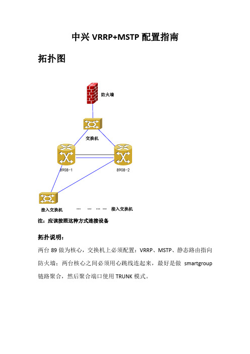
中兴VRRP+MSTP配置指南拓扑图接入交换机…………接入交换机注:应该按照这种方式连接设备拓扑说明:两台89做为核心,交换机上必须配置:VRRP、MSTP、静态路由指向防火墙;两台核心之间必须用心跳线连起来,最好是做smartgroup 链路聚合,然后聚合端口使用TRUNK模式。
配置实例例如,内网有2个业务VLAN,分别是VLAN 10和VLAN 20,上联防火墙的是VLAN 100,假设防火墙的内网口地址是192.168.100.1。
假设两台89之间都使用gei_1/23和gei_1/24口连接起来。
8908-1配置(主):定义所有VLAN:conf tvlan 10name yewu1exitvlan 20name yewu2exitvlan 100name to-firewallexit配置网关地址,做VRRP的所有网关地址,必须分配三个地址,其中两个地址是Intvlan的实际地址,一个是VRRP的浮动地址:intvlan 10ip add 192.168.10.252 255.255.255.0vrrp 1 ip 192.168.10.254exitintvlan 20ip add 192.168.20.252 255.255.255.0vrrp 2 ip 192.168.20.254exitintvlan 100ip add 192.168.100.252 255.255.255.0vrrp 3 ip 192.168.100.254exit配置STP和优先级:spanning-tree enablespanning-treemst instance 0 priority 0定义聚合端口smartgroup:interface smartgroup1exit把23和24加入聚合端口:interface gei_1/23smartgroup 1 mode onexitinterface gei_1/24smartgroup 1 mode onexit把聚合端口配置成trunk模式,并将所有VLAN 透传:interface smartgroup1switchport mode trunkswitchport trunk vlan 10switchport trunk vlan 20switchport trunk vlan 100exit配置静态路由:ip route 0.0.0.0 0.0.0.0 192.168.100.18908-2配置(备):conf tvlan 10name yewu1exitvlan 20name yewu2exitvlan 100name to-firewallexitintvlan 10ip add 192.168.10.253vrrp 1 ip 192.168.10.254exitintvlan 20ip add 192.168.20.253vrrp 2 ip 192.168.20.254exitintvlan 100ip add 192.168.100.253vrrp 3 ip 192.168.100.254exitspanning-tree enablespanning-treemst instance 0 priority 4096interface smartgroup1exitinterface gei_1/23smartgroup 1 mode onexitinterface gei_1/24smartgroup 1 mode onexitinterface smartgroup1switchport mode trunkswitchport trunk vlan 10switchport trunk vlan 20switchport trunk vlan 100exitip route 0.0.0.0 0.0.0.0 192.168.100.1按照上面的配置,任意关闭一台核心交换机,将不会影响用户上网。
企业网络VRRP+MSTP负载均衡配置案例
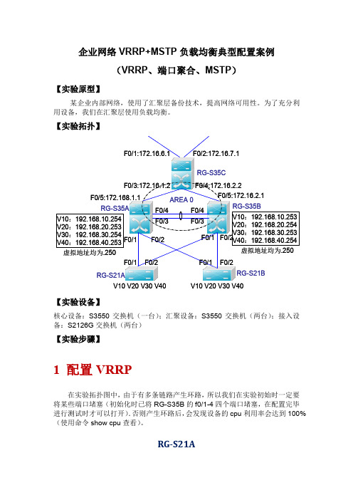
RG-S35A
需要做出 standby,vlan10、20、30、40 的虚拟 ip,以及上连的路由口配置,以及 OSPF 动 态路由
RG-S35A(config)#vlan 10
!!创建 VLAN10、20、30 和 40
RG-S35A(config-vlan)#exit ……
RG-S35A(config)#interface vlan 10
!设为抢占模式
RG-S35A(config-if)#standby 1 priority 254
!VLAN10 的 standby 优先级设为 254
RG-S35A(config-if)#exit 虚拟 IP: 每一个 standby 都有一个虚拟 IP 地址,在 35A 的 VLAN10 上有这个地址,在 35B 的 VLAN10 上也有这个 IP 地址,作为下连终端设备的网关。下连在 VLAN10 的终端设备,将网关设为这 个地址。终端设备只要知道自己网关的 IP 地址即可,具体哪台设备上的网关生效,工作交 给 standby 优先级来做. 抢占模式: 在正常状况下,VLAN10 的数据由 35A 传输.当 35A 发生故障时,则由 35B 担负起传输任务.若 不配置抢占模式,当 35A 恢复正常后,则仍由 35B 传输;配置抢占模式后,正常后的 35A 会再 次夺取对 VLAN10 的控制权. 优先级:
!配置虚拟 IP
RG-S35B(config-if)#standby 1 preempt
!设为抢占模式
RG-S35B(config-if)#exit
RG-S35B(config)#interface vlan 20 RG-S35B(config-if)#ip address 192.168.30.254 255.255.255.0
H3C S9500交换机VRRP+MSTP配置举例
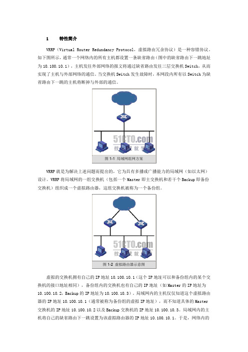
1 特性简介VRRP(Virtual Router Redundancy Protocol,虚拟路由冗余协议)是一种容错协议。
如下图所示,通常一个网络内的所有主机都设置一条缺省路由(图中的缺省路由下一跳地址为10.100.10.1),主机发往外部网络的报文将通过缺省路由发往三层交换机Switch,从而实现了主机与外部网络的通信。
当交换机Switch发生故障时,本网段内所有以Switch为缺省路由下一跳的主机将断掉与外部的通信。
VRRP就是为解决上述问题而提出的,它为具有多播或广播能力的局域网(如以太网)设计。
VRRP将局域网的一组交换机(包括一个Master即主交换机和若干个Backup即备份交换机)组织成一个虚拟路由器,这组交换机被称为一个备份组。
虚拟的交换机拥有自己的IP地址10.100.10.1(这个IP地址可以和备份组内的某个交换机的接口地址相同),备份组内的交换机也有自己的IP地址(如Master的IP地址为10.100.10.2,Backup的IP地址为10.100.10.3)。
局域网内的主机仅仅知道这个虚拟路由器的IP地址10.100.10.1(通常被称为备份组的虚拟IP地址),而不知道具体的Master 交换机的IP地址10.100.10.2以及Backup交换机的IP地址10.100.10.3。
局域网内的主机将自己的缺省路由下一跳设置为该虚拟路由器的IP地址10.100.10.1。
于是,网络内的主机就通过这个虚拟的交换机与其它网络进行通信。
当备份组内的Master交换机不能正常工作时,备份组内的其它Backup交换机将接替不能正常工作的Master交换机成为新的Master交换机,继续向网络内的主机提供路由服务,从而实现网络内的主机不间断地与外部网络进行通信。
2 适用版本软件版本:S9500-CMW310-R1628版本及以后升级版本(R2126及以上版本不支持)硬件版本:S9500交换机全系列硬件版本3 注意事项同一VRRP备份组多个备份的路由器之间,VRRP组握手时间必须一致,否则VRRP组状态会异常;同一VRRP备份组之间VRRP的工作方式必须相同,都为抢占模式,或者都为非抢占模式;必须在配置VRRP组之前启用vrrp ping-enable功能,否则无法ping通VRRP虚地址;VRRP监控端口只能监控VLAN接口地址,无法监控某个具体的端口;VRRP组的hello时间一般不建议修改;如果VRRP组数较多,可以考虑把各组的hello 时间分别设置成2、3、5、7等互质数,减少VRRP hello报文对CPU的冲击。
mstp加vrrp的实验例子
mstp加vrrp的实验例子
以下是一个使用MSTP和VRRP的实验例子:
设备1和设备2之间连接了多个交换机,其中设备1运行VRRP,并且是虚拟路由器组的主机,设备2是备用主机。
步骤:
1. 配置设备1上的VRRP:
- 为虚拟路由器组配置一个组ID和虚拟IP地址。
- 设置设备1为虚拟路由器组的主机,优先级较高。
- 配置其他参数,如优先级、优先级降级的阈值等。
2. 配置MSTP:
- 配置多个VLAN,并且将它们绑定到MSTP实例上。
- 在每个交换机上启用MSTP,并设置实例根桥和桥优先级。
- 配置MSTP的端口优先级,用于控制MSTP的选举。
3. 设置MSTP的根桥:
- 在所有交换机上使用根桥优先级来选择根桥。
- 所有其他交换机通过MSTP协议来确定每个VLAN的根桥。
4. 设置VRRP虚拟路由器组的VIP下的MSTP实例的根桥:
- 在虚拟路由器组的VIP所属的MSTP实例上,设置根桥优
先级为最低。
- 这将确保VRRP主机上的MSTP实例被选为根桥。
5. 配置设备2上的VRRP:
- 配置相同的组ID和虚拟IP地址。
- 设置设备2为备用主机。
- 配置优先级较低,以确保设备1成为主机。
6. 测试:
- 断开设备1和设备2之间的连接,观察VRRP主机的切换过程。
- 在交换机上查看MSTP实例的状态,确保根桥已更改,以维持虚拟路由器的正常工作。
通过使用MSTP和VRRP,可以实现对网络中的故障进行快速检测和恢复,提高网络的可靠性和冗余性。
VRRP与MSTP综合组网配置举例

VRRP与MSTP综合组网配置举例1 特性简介1.1 VRRP简介1.2 MSTP简介2 应用场合2.1 单独使用VRRP的组网方式2.2 VRRP与MSTP配合使用的组网方式3 配置前提4 配置举例4.1 组网需求4.2 配置思路4.3 配置步骤4.3.1 设备A的配置4.3.2 设备B的配置4.3.3 设备C的配置4.3.4 设备D的配置4.3.5 设备E的配置4.3.6 主机的配置4.4 验证配置4.5 配置文件5 相关资料1 特性简介1.1 VRRP简介VRRP用来为网关设备提供冗余备份。
如图1-1所示,VRRP将可以承担网关功能的一组设备加入到备份组中,形成一台虚拟路由器,局域网内的主机将此虚拟路由器设置为缺省网关。
VRRP根据优先级从备份组中选举出一台网关设备作为Master,负责转发局域网内主机与外部通信的流量,其他网关设备作为Backup。
当Master出现故障后,VRRP重新选举新的Master,保证流量转发不会中断。
图1-1 虚拟路由器示意图VRRP可以监视上行接口或链路的状态。
当路由器的上行接口或链路出现故障时,该路由器主动降低自己的优先级,使得备份组内其它路由器的优先级高于这个路由器,以避免这个路由器成为Master,导致流量转发失败。
1.2 MSTP简介MSTP是在STP的基础上发展而来的,用于在局域网中消除数据链路层的物理环路。
作为一种二层管理协议,MSTP通过选择性地阻塞网络中的冗余链路来消除二层环路,将环路网络结构修剪成无环路的树型网络结构,从而防止报文在环路网络中不断增生和无限循环,避免设备由于重复接收相同报文而造成报文处理能力的下降;同时,它还具备链路备份的功能。
与STP相比,MSTP可以实现网络拓扑的快速收敛,也能使不同VLAN的流量沿各自的路径转发,从而为冗余链路提供了更好的负载分担机制。
2 应用场合2.1 单独使用VRRP的组网方式图1-2 VRRP为网关提供冗余备份单独使用VRRP为网关提供冗余备份的组网方式如图1-2所示:局域网内的主机通过二层交换机接入两台网关设备Device A和Device B,Device A和Device B构成一台虚拟路由器,为网关提供冗余备份,以提高网关设备的可靠性。
交换机 vrrp+mstp配置实例,含均衡负载(大赛人原文)

交换机 vrrp+mstp配置实例,含均衡负载(大赛人原文)交换机vrrp+mstp配置实例,含均衡负载(大赛人原文)交换机vrrp+mstp配置实例锐捷tac贾文宇一、组网需求1、switcha、switchb采用两台锐捷的s5750;switchc、shwichd挑选用锐捷的s3750和s37602、全网共计两个业务vlan,为vlan10、vlan203、switcha、switchb都分别对两vlan提拔两vrrp组与,同时实现两组的业务的负载分担和备份。
4、switcha、switchb、switchc、switchd都提拔mstp多分解成数协议,并且所有设备都属于同一个mst域,且实例映射一致(vlan10映射实例1、vlan20映射实例2其他vlan映射默认实例0)。
5、vlan10业务以switcha为根桥;vlan20业务以switchb为根桥;同时实现力阻断网络环路,并能实现不同vlan数据流负载分担功能。
二、数据传输图三、配置步骤switcha布局:s1#showrunbuildingconfiguration...currentconfiguration:1651bytes!versionrgnos10.2.00(2),release(29287)(tuedec2520:39:14cst2021-ngcf49)hostnames1co-operateenablevlan1!vlan10!vlan20!!noservicepassword-encryption!spanning-tree开启生成树(默认为mstp)spanning-treemstconfiguration步入mst布局模式revision1选定mstrevisionnumber为1nameregion1选定mst布局名称instance0vlan1-9,11-19,21-4094缺省情况下vlan都属于实例0instance1vlan10手工指定vlan10属于实例1instance2vlan20手工指定vlan20属于实例2spanning-treemst1priority0选定实例1的优先级为0(为根桥)spanning-treemst2priority4096选定实例2的优先级为4096interfacegigabitethernet0/1switchportaccessvlan10配置g0/1属于vlan10!interfacegigabitethernet0/2switchportaccessvlan20配置g0/2属于vlan20!interfacegigabitethernet0/3!..interfacegigabitethernet0/24设置g0/24为trunk接口且允许vlan10/20通过switchportmodetrunk!interfacevlan10建立vlan10sviUSBipaddress192.168.10.1255.255.255.0布局ip 地址vrrp1priority120配置vrrp组1优先级为120vrrp1ip192.168.10.254布局vrrp组与1交互式ip地址为192.168.10.254!interfacevlan20创建vlan20svi接口ipaddress192.168.20.1255.255.255.0配置ip地址vrrp2ip192.168.20.254布局vrrp组与2交互式ip地址为192.168.20.254预设vrrp组的优先级为100预设不表明!linecon0linevty04logins1#showvlanvlannamestatusports-------------------------------------------------------------------------------1vlan0001staticgi0/3,gi0/4,gi0/5,gi0/6gi0/7,gi0/8,gi0/9,gi0/10gi0/11,gi0/12,gi0/13,gi0/14gi0/15,gi0/16,gi0/17,gi0/18gi0/19,gi0/20,gi0/21,gi0/22gi0/23,gi0/2410vlan0010staticgi0/1,gi0/2420vlan0020staticgi0/2,gi0/24switchb布局:s2#showrunbuildingconfiguration...currentconfiguration:1607bytes!versionrgnos10.2.00(2),release(27932)(thudec1310:32:09cst2021-ngcf31)hostnames2vlan1!vlan10!vlan20!!noservicepassword-encryption!spanning-treespanning-treemstconfigurationrevision1nameregion1instance0vlan1-9,11-19,21-4094instance1vlan10instance2vlan20spanning-treemst1priority4096spanning-treemst2priority0interfacegigabitethernet0/1switchportaccessvlan10!interfacegigabitethernet0/2switchportaccessvlan20!..interfacegigabitethernet0/24switchportmodetrunk!interfacevlan10ipaddress192.168.10.2255.255.255.0vrrp1ip192.168.10.254!interfacevlan20ipaddress192.168.20.2255.255.255.0vrrp2priority120vrrp2ip192.168.20.254!linecon0linevty04login!!ends2#showvlanvlannamestatusports--------------------------------------------------------------------------------1vlan0001staticgi0/3,gi0/4,gi0/5,gi0/6gi0/7,gi0/8,gi0/9,gi0/10gi0/11,gi0/12,gi0/13,gi0/14gi0/15,gi0/16,gi0/17,gi0/18gi0/19,gi0/20,gi0/21,gi0/22gi0/23,gi0/2410vlan0010staticgi0/1,gi0/2420vlan0020staticgi0/2,gi0/24switchc配置:。
MSTP+VRRP双机热备配置

MSTP&VRRP双机热备配置范例1system参数配置system是属于EX交换机基本配置部分,在进行其它配置之前需要先完成该部分内容配置,主要配置工作如下:(1)设置root密码(2)设置主机名(3)设置日期时间(4)添加用户(5)开启ssh/telnet/http服务(6)设置DNS(可选配置)(7)分配新的用户权限(可选配置)(8)设置NTP服务器(可选配置)1.1设置Root密码交换机初始化用户名是root是没有密码的,在进行commit之前必须修改root密码。
1.2设置主机名1.3设置DNS服务器1.4设置日期时间设置命令:1.5设置NTP服务器1.6开启远程Telnet登录服务说明:在默认缺省配置下,EX交换机只是开放了http远程登陆方式,因此如果想通过telnet登陆到交换机上,必须在系统中打开telnet服务。
设置命令:删除命令:1.7开启远程Ftp服务说明:在默认缺省配置下,EX交换机只是开放了http远程登陆方式,因此如果想通过ftp上传文件,例如OS或者配置到交换机上,必须在系统中打开ftp服务。
设置命令:1.8开启远程SSH登陆说明:如果想通过更加安全的ssh登陆到交换机,需要在交换机上打开ssh服务。
设置命令:1.9开启远程HTTP登陆说明:在默认缺省配置下,EX交换机已经开放了http远程登陆方式。
设置命令:删除命令:1.10添加用户2实验环境描述2.1实验拓扑图2.2实验IP规划2.2.1Wan节点2.2.2CoreSW1(EX4200-1)2.2.3CoreSW2(EX4200-2)2.2.4虚拟交换机2.3连接整体描述Wan路由器Ge-0/0/1.0和Ge-0/0/2.0分别下接CoreSW1和CoreSW2的Ge-0/0/23.0 CoreSW1和CoreSW2交换机的Ge-0/0/1.0——Ge-0/0/4.0分别下接L2SW1——L2SW4的Fa0/24和Fa0/23,两交换机的Ge-0/0/8.0和Ge-0/0/9.0互联。
- 1、下载文档前请自行甄别文档内容的完整性,平台不提供额外的编辑、内容补充、找答案等附加服务。
- 2、"仅部分预览"的文档,不可在线预览部分如存在完整性等问题,可反馈申请退款(可完整预览的文档不适用该条件!)。
- 3、如文档侵犯您的权益,请联系客服反馈,我们会尽快为您处理(人工客服工作时间:9:00-18:30)。
交换机vrrp+mstp配置实例锐捷tac贾文宇一、组网需求1、switch a 、switch b选用两台锐捷的s5750 ;switch c 、shwich d 选用锐捷的s3750和s37602、全网共有两个业务vlan ,为vlan 10 、vlan 203、Switch a 、switch b 都分别对两vlan起用两vrrp组,实现两组的业务的负载分担和备份。
4、Switch a、switch b、switch c、switch d 都起用mstp多生成数协议,并且所有设备都属于同一个mst域,且实例映射一致(vlan 10映射实例1、vlan 20映射实例2 其他vlan映射默认实例0)。
5、Vlan 10业务以switch a为根桥;vlan 20业务以switch b为根桥;实现阻断网络环路,并能实现不同vlan数据流负载分担功能。
二、组网图三、配置步骤Switch a配置:s1#show runBuilding configuration...Current configuration : 1651 bytes!version RGNOS 10.2.00(2), Release(29287)(Tue Dec 25 20:39:14 CST 2007 -ngcf49) hostname s1co-operate enable!!!vlan 1!vlan 10!vlan 20!!no service password-encryption!spanning-tree 开启生成树(默认为mstp)spanning-tree mst configuration 进入mst配置模式revision 1 指定MST revision number 为1name region1 指定mst配置名称instance 0 vlan 1-9, 11-19, 21-4094 缺省情况下vlan都属于实例0instance 1 vlan 10 手工指定vlan10属于实例1instance 2 vlan 20 手工指定vlan20属于实例2spanning-tree mst 1 priority 0 指定实例1的优先级为0(为根桥)spanning-tree mst 2 priority 4096 指定实例2的优先级为4096interface GigabitEthernet 0/1switchport access vlan 10 配置g0/1属于vlan10!interface GigabitEthernet 0/2switchport access vlan 20 配置g0/2属于vlan 20!interface GigabitEthernet 0/3!..interface GigabitEthernet 0/24 设置g0/24为trunk接口且允许vlan10/20通过switchport mode trunk!interface VLAN 10 创建vlan 10 svi接口ip address 192.168.10.1 255.255.255.0 配置ip地址vrrp 1 priority 120 配置vrrp组1 优先级为120vrrp 1 ip 192.168.10.254 配置vrrp组1虚拟ip地址为192.168.10.254!interface VLAN 20 创建vlan 20 svi接口ip address 192.168.20.1 255.255.255.0 配置ip地址vrrp 2 ip 192.168.20.254 配置vrrp组2虚拟ip地址为192.168.20.254默认vrrp组的优先级为100默认不显示!line con 0line vty 0 4logins1#show vlanVLAN Name Status Ports---- -------------------------------- --------- ----------------------------------1 VLAN0001 STA TIC Gi0/3, Gi0/4, Gi0/5, Gi0/6Gi0/7, Gi0/8, Gi0/9, Gi0/10Gi0/11, Gi0/12, Gi0/13, Gi0/14Gi0/15, Gi0/16, Gi0/17, Gi0/18Gi0/19, Gi0/20, Gi0/21, Gi0/22Gi0/23, Gi0/2410 VLAN0010 STATIC Gi0/1, Gi0/2420 VLAN0020 STATIC Gi0/2, Gi0/24Switch b配置:s2#show runBuilding configuration...Current configuration : 1607 bytes!version RGNOS 10.2.00(2), Release(27932)(Thu Dec 13 10:32:09 CST 2007 -ngcf31) hostname s2!!!vlan 1!vlan 10!vlan 20!!no service password-encryption!spanning-treespanning-tree mst configurationrevision 1name region1instance 0 vlan 1-9, 11-19, 21-4094instance 1 vlan 10instance 2 vlan 20spanning-tree mst 1 priority 4096spanning-tree mst 2 priority 0interface GigabitEthernet 0/1switchport access vlan 10!interface GigabitEthernet 0/2switchport access vlan 20!..interface GigabitEthernet 0/24switchport mode trunk!interface VLAN 10ip address 192.168.10.2 255.255.255.0vrrp 1 ip 192.168.10.254!interface VLAN 20ip address 192.168.20.2 255.255.255.0vrrp 2 priority 120vrrp 2 ip 192.168.20.254!line con 0line vty 0 4login!!ends2#show vlanVLAN Name Status Ports---- -------------------------------- --------- -----------------------------------1 VLAN0001 STA TIC Gi0/3, Gi0/4, Gi0/5, Gi0/6Gi0/7, Gi0/8, Gi0/9, Gi0/10Gi0/11, Gi0/12, Gi0/13, Gi0/14Gi0/15, Gi0/16, Gi0/17, Gi0/18Gi0/19, Gi0/20, Gi0/21, Gi0/22Gi0/23, Gi0/2410 VLAN0010 STATIC Gi0/1, Gi0/2420 VLAN0020 STATIC Gi0/2, Gi0/24Switch c配置:s3#show runBuilding configuration...Current configuration : 1540 bytes!version RGNOS 10.2.00(2), Release(28794)(Fri Dec 21 09:27:15 CST 2007 -ngcf32) hostname s3!vlan 1!vlan 10!!service password-encryption!spanning-treespanning-tree mst configurationrevision 1name region1instance 0 vlan 1-9, 11-19, 21-4094instance 1 vlan 10instance 2 vlan 20spanning-tree mst 1 priority 0spanning-tree mst 2 priority 4096interface FastEthernet 0/1switchport access vlan 10!interface FastEthernet 0/2switchport access vlan 10!..interface GigabitEthernet 0/25!interface GigabitEthernet 0/26!interface GigabitEthernet 0/27!interface GigabitEthernet 0/28!interface VLAN 10ip address 192.168.10.3 255.255.255.0ip route 0.0.0.0 0.0.0.0 192.168.10.254!!line con 0line vty 0 4loginSwitch d配置:s4#show runBuilding configuration...Current configuration : 1066 bytes!version RGNOS 10.2.00(2), Release(27932)(Thu Dec 13 10:31:41 CST 2007 -ngcf32) hostname s4!vlan 1!vlan 20!!no service password-encryption!spanning-treespanning-tree mst configurationrevision 1name region1instance 0 vlan 1-9, 11-19, 21-4094instance 1 vlan 10instance 2 vlan 20spanning-tree mst 1 priority 4096spanning-tree mst 2 priority 0interface GigabitEthernet 0/1switchport access vlan 20!interface GigabitEthernet 0/2switchport access vlan 20!..interface GigabitEthernet 0/12!interface VLAN 20ip address 192.168.20.3 255.255.255.0!!!!ip route 0.0.0.0 0.0.0.0 192.168.20.254!!line con 0line vty 0 4login!四、查看vrrp、mstp信息Switch a 信息:s1#show vrrp 查看vrrp 信息VLAN 10 - Group 1State is MasterVirtual IP address is 192.168.10.254 configured Virtual MAC address is 0000.5e00.0101 Advertisement interval is 1 secPreemption is enabledmin delay is 0 secPriority is 120Master Router is 192.168.10.1 (local), priority is 120 Master Advertisement interval is 1 secMaster Down interval is 3 secVLAN 20 - Group 2State is BackupVirtual IP address is 192.168.20.254 configured Virtual MAC address is 0000.5e00.0102 Advertisement interval is 1 secPreemption is enabledmin delay is 0 secPriority is 100Master Router is 192.168.20.2 , priority is 120 Master Advertisement interval is 1 secMaster Down interval is 3 secs1#s1#s1#s1#show spanning-tree interface gigabitEthernet 0/1 查看g0/1接口stp状态信息PortAdminPortFast : DisabledPortOperPortFast : DisabledPortAdminAutoEdge : EnabledPortOperAutoEdge : DisabledPortAdminLinkType : autoPortOperLinkType : point-to-pointPortBPDUGuard : DisabledPortBPDUFilter : Disabled###### MST 0 vlans mapped :1-9, 11-19, 21-4094PortState : forwardingPortPriority : 128PortDesignatedRoot : 8000.001a.a909.8fe0PortDesignatedCost : 0PortDesignatedBridge :8000.00d0.f836.ed70PortDesignatedPort : 8001PortForwardTransitions : 6PortAdminPathCost : 200000PortOperPathCost : 200000PortRole : designatedPort###### MST 1 vlans mapped :10PortState : forwardingPortPriority : 128PortDesignatedRoot : 0001.00d0.f823.ef82PortDesignatedCost : 0PortDesignatedBridge :0001.00d0.f823.ef82PortDesignatedPort : 8001PortForwardTransitions : 5PortAdminPathCost : 200000PortOperPathCost : 200000PortRole : rootPort###### MST 2 vlans mapped :20PortState : forwardingPortPriority : 128PortDesignatedRoot : 0002.001a.a909.8fe0PortDesignatedCost : 0PortDesignatedBridge :1002.00d0.f836.ed70PortDesignatedPort : 8001PortForwardTransitions : 4PortAdminPathCost : 200000PortOperPathCost : 200000PortRole : designatedPorts1#s1#s1#show spanning-tree interface gigabitEthernet 0/2 查看g0/2接口stp状态信息PortAdminPortFast : DisabledPortOperPortFast : DisabledPortAdminAutoEdge : EnabledPortOperAutoEdge : DisabledPortAdminLinkType : autoPortOperLinkType : point-to-pointPortBPDUGuard : DisabledPortBPDUFilter : Disabled###### MST 0 vlans mapped :1-9, 11-19, 21-4094PortState : forwardingPortPriority : 128PortDesignatedRoot : 8000.001a.a909.8fe0PortDesignatedCost : 0PortDesignatedBridge :8000.00d0.f836.ed70PortDesignatedPort : 8002PortForwardTransitions : 5PortAdminPathCost : 20000PortOperPathCost : 20000PortRole : designatedPort###### MST 1 vlans mapped :10PortState : forwardingPortPriority : 128PortDesignatedRoot : 0001.00d0.f823.ef82PortDesignatedCost : 0PortDesignatedBridge :0001.00d0.f836.ed70PortDesignatedPort : 8002PortForwardTransitions : 4PortAdminPathCost : 20000PortOperPathCost : 20000PortRole : designatedPort###### MST 2 vlans mapped :20PortState : discardingPortPriority : 128PortDesignatedRoot : 0002.001a.a909.8fe0PortDesignatedCost : 0PortDesignatedBridge :0002.00d0.f8d7.ae12PortDesignatedPort : 8002PortForwardTransitions : 3PortAdminPathCost : 20000PortOperPathCost : 20000PortRole : alternatePorts1#s1#s1#show spanning-tree interface gigabitEthernet 0/24 g0/24接口stp状态信息PortAdminPortFast : DisabledPortOperPortFast : DisabledPortAdminAutoEdge : EnabledPortOperAutoEdge : DisabledPortAdminLinkType : autoPortOperLinkType : point-to-pointPortBPDUGuard : DisabledPortBPDUFilter : Disabled###### MST 0 vlans mapped :1-9, 11-19, 21-4094PortState : forwardingPortPriority : 128PortDesignatedRoot : 8000.001a.a909.8fe0PortDesignatedCost : 0PortDesignatedBridge :8000.001a.a909.8fe0PortDesignatedPort : 8018PortForwardTransitions : 5PortAdminPathCost : 20000PortOperPathCost : 20000PortRole : rootPort###### MST 1 vlans mapped :10PortState : forwardingPortPriority : 128PortDesignatedRoot : 0001.00d0.f823.ef82PortDesignatedCost : 0PortDesignatedBridge :0001.00d0.f836.ed70PortDesignatedPort : 8018PortForwardTransitions : 5PortAdminPathCost : 20000PortOperPathCost : 20000PortRole : designatedPort###### MST 2 vlans mapped :20PortState : forwardingPortPriority : 128PortDesignatedRoot : 0002.001a.a909.8fe0 PortDesignatedCost : 0PortDesignatedBridge :0002.001a.a909.8fe0 PortDesignatedPort : 8018 PortForwardTransitions : 4PortAdminPathCost : 20000PortOperPathCost : 20000PortRole : rootPorts1#Switch b 信息:s2#show vrrpVLAN 10 - Group 1State is BackupVirtual IP address is 192.168.10.254 configured Virtual MAC address is 0000.5e00.0101 Advertisement interval is 1 secPreemption is enabledmin delay is 0 secPriority is 100Master Router is 192.168.10.1 , priority is 120 Master Advertisement interval is 1 secMaster Down interval is 3 secVLAN 20 - Group 2State is MasterVirtual IP address is 192.168.20.254 configured Virtual MAC address is 0000.5e00.0102 Advertisement interval is 1 secPreemption is enabledmin delay is 0 secPriority is 120Master Router is 192.168.20.2 (local), priority is 120 Master Advertisement interval is 1 secMaster Down interval is 3 secs2#s2#s2#s2#s2#s2#s2#show spanning-tree interface gigabitEthernet 0/1 PortAdminPortFast : Disabled PortOperPortFast : Disabled PortAdminAutoEdge : Enabled PortOperAutoEdge : Disabled PortAdminLinkType : autoPortOperLinkType : point-to-point PortBPDUGuard : DisabledPortBPDUFilter : Disabled###### MST 0 vlans mapped :1-9, 11-19, 21-4094 PortState : forwardingPortPriority : 128PortDesignatedRoot : 8000.001a.a909.8fe0 PortDesignatedCost : 0 PortDesignatedBridge :8000.001a.a909.8fe0 PortDesignatedPort : 8001 PortForwardTransitions : 1 PortAdminPathCost : 200000 PortOperPathCost : 200000PortRole : designatedPort###### MST 1 vlans mapped :10PortState : forwardingPortPriority : 128PortDesignatedRoot : 0001.00d0.f823.ef82 PortDesignatedCost : 0 PortDesignatedBridge :0001.00d0.f823.ef82 PortDesignatedPort : 8002 PortForwardTransitions : 2 PortAdminPathCost : 200000 PortOperPathCost : 200000PortRole : rootPort###### MST 2 vlans mapped :20PortState : forwardingPortPriority : 128PortDesignatedRoot : 0002.001a.a909.8fe0 PortDesignatedCost : 0 PortDesignatedBridge :0002.001a.a909.8fe0 PortDesignatedPort : 8001PortForwardTransitions : 1 PortAdminPathCost : 200000 PortOperPathCost : 200000PortRole : designatedPorts2#s2#s2#s2#show spanning-tree interface gigabitEthernet 0/2 PortAdminPortFast : Disabled PortOperPortFast : Disabled PortAdminAutoEdge : Enabled PortOperAutoEdge : Disabled PortAdminLinkType : autoPortOperLinkType : point-to-point PortBPDUGuard : DisabledPortBPDUFilter : Disabled###### MST 0 vlans mapped :1-9, 11-19, 21-4094 PortState : forwardingPortPriority : 128PortDesignatedRoot : 8000.001a.a909.8fe0 PortDesignatedCost : 0 PortDesignatedBridge :8000.001a.a909.8fe0 PortDesignatedPort : 8002 PortForwardTransitions : 1 PortAdminPathCost : 20000 PortOperPathCost : 20000PortRole : designatedPort###### MST 1 vlans mapped :10PortState : forwardingPortPriority : 128PortDesignatedRoot : 0001.00d0.f823.ef82 PortDesignatedCost : 0 PortDesignatedBridge :1001.001a.a909.8fe0 PortDesignatedPort : 8002 PortForwardTransitions : 2 PortAdminPathCost : 20000 PortOperPathCost : 20000PortRole : designatedPort###### MST 2 vlans mapped :20PortState : forwardingPortPriority : 128PortDesignatedRoot : 0002.001a.a909.8fe0 PortDesignatedCost : 0PortDesignatedBridge :0002.001a.a909.8fe0 PortDesignatedPort : 8002 PortForwardTransitions : 1PortAdminPathCost : 20000PortOperPathCost : 20000PortRole : designatedPorts2#s2#s2#s2#s2#show spanning-tree interface gigabitEthernet 0/24 PortAdminPortFast : Disabled PortOperPortFast : Disabled PortAdminAutoEdge : Enabled PortOperAutoEdge : Disabled PortAdminLinkType : autoPortOperLinkType : point-to-point PortBPDUGuard : DisabledPortBPDUFilter : Disabled###### MST 0 vlans mapped :1-9, 11-19, 21-4094 PortState : forwardingPortPriority : 128PortDesignatedRoot : 8000.001a.a909.8fe0 PortDesignatedCost : 0PortDesignatedBridge :8000.001a.a909.8fe0 PortDesignatedPort : 8018 PortForwardTransitions : 1PortAdminPathCost : 20000PortOperPathCost : 20000PortRole : designatedPort###### MST 1 vlans mapped :10PortState : discardingPortPriority : 128PortDesignatedRoot : 0001.00d0.f823.ef82 PortDesignatedCost : 0PortDesignatedBridge :0001.00d0.f836.ed70 PortDesignatedPort : 8018 PortForwardTransitions : 1PortAdminPathCost : 20000 PortOperPathCost : 20000PortRole : alternatePort###### MST 2 vlans mapped :20PortState : forwardingPortPriority : 128PortDesignatedRoot : 0002.001a.a909.8fe0 PortDesignatedCost : 0 PortDesignatedBridge :0002.001a.a909.8fe0 PortDesignatedPort : 8018 PortForwardTransitions : 1 PortAdminPathCost : 20000 PortOperPathCost : 20000PortRole : designatedPorts2#Switch c 信息:s3#show spanning-tree interface fastEthernet 0/1 PortAdminPortFast : Disabled PortOperPortFast : Disabled PortAdminAutoEdge : Enabled PortOperAutoEdge : Disabled PortAdminLinkType : auto PortOperLinkType : point-to-point PortBPDUGuard : DisabledPortBPDUFilter : Disabled###### MST 0 vlans mapped :1-9, 11-19, 21-4094 PortState : discardingPortPriority : 128PortDesignatedRoot : 8000.001a.a909.8fe0 PortDesignatedCost : 0 PortDesignatedBridge :8000.00d0.f836.ed70 PortDesignatedPort : 8001 PortForwardTransitions : 1 PortAdminPathCost : 200000 PortOperPathCost : 200000PortRole : alternatePort###### MST 1 vlans mapped :10PortState : forwardingPortPriority : 128PortDesignatedRoot : 0001.00d0.f823.ef82 PortDesignatedCost : 0 PortDesignatedBridge :0001.00d0.f823.ef82 PortDesignatedPort : 8001 PortForwardTransitions : 1 PortAdminPathCost : 200000 PortOperPathCost : 200000PortRole : designatedPort###### MST 2 vlans mapped :20PortState : discardingPortPriority : 128PortDesignatedRoot : 0002.001a.a909.8fe0 PortDesignatedCost : 0 PortDesignatedBridge :1002.00d0.f836.ed70 PortDesignatedPort : 8001 PortForwardTransitions : 0 PortAdminPathCost : 200000 PortOperPathCost : 200000PortRole : alternatePorts3#s3#s3#s3#s3#show spanning-tree interface fastEthernet 0/2 PortAdminPortFast : Disabled PortOperPortFast : Disabled PortAdminAutoEdge : Enabled PortOperAutoEdge : Disabled PortAdminLinkType : auto PortOperLinkType : point-to-point PortBPDUGuard : DisabledPortBPDUFilter : Disabled###### MST 0 vlans mapped :1-9, 11-19, 21-4094 PortState : forwardingPortPriority : 128PortDesignatedRoot : 8000.001a.a909.8fe0 PortDesignatedCost : 0 PortDesignatedBridge :8000.001a.a909.8fe0 PortDesignatedPort : 8001PortForwardTransitions : 1 PortAdminPathCost : 200000 PortOperPathCost : 200000PortRole : rootPort###### MST 1 vlans mapped :10PortState : forwardingPortPriority : 128PortDesignatedRoot : 0001.00d0.f823.ef82 PortDesignatedCost : 0 PortDesignatedBridge :0001.00d0.f823.ef82 PortDesignatedPort : 8002 PortForwardTransitions : 2 PortAdminPathCost : 200000 PortOperPathCost : 200000PortRole : designatedPort###### MST 2 vlans mapped :20PortState : forwardingPortPriority : 128PortDesignatedRoot : 0002.001a.a909.8fe0 PortDesignatedCost : 0 PortDesignatedBridge :0002.001a.a909.8fe0 PortDesignatedPort : 8001 PortForwardTransitions : 1 PortAdminPathCost : 200000 PortOperPathCost : 200000PortRole : rootPorts3#Switch d 信息:s4#show spanning-tree interface gigabitEthernet 0/1 PortAdminPortFast : Disabled PortOperPortFast : Disabled PortAdminAutoEdge : Enabled PortOperAutoEdge : Disabled PortAdminLinkType : autoPortOperLinkType : point-to-point PortBPDUGuard : DisabledPortBPDUFilter : Disabled###### MST 0 vlans mapped :1-9, 11-19, 21-4094 PortState : forwardingPortPriority : 128PortDesignatedRoot : 8000.001a.a909.8fe0 PortDesignatedCost : 0 PortDesignatedBridge :8000.001a.a909.8fe0 PortDesignatedPort : 8002 PortForwardTransitions : 1 PortAdminPathCost : 20000 PortOperPathCost : 20000PortRole : rootPort###### MST 1 vlans mapped :10PortState : discardingPortPriority : 128PortDesignatedRoot : 0001.00d0.f823.ef82 PortDesignatedCost : 0 PortDesignatedBridge :1001.001a.a909.8fe0 PortDesignatedPort : 8002 PortForwardTransitions : 1 PortAdminPathCost : 20000 PortOperPathCost : 20000PortRole : alternatePort###### MST 2 vlans mapped :20PortState : forwardingPortPriority : 128PortDesignatedRoot : 0002.001a.a909.8fe0 PortDesignatedCost : 0 PortDesignatedBridge :0002.001a.a909.8fe0 PortDesignatedPort : 8002 PortForwardTransitions : 1 PortAdminPathCost : 20000 PortOperPathCost : 20000PortRole : rootPorts4#s4#s4#s4#show spanning-tree interface gigabitEthernet 0/2 PortAdminPortFast : Disabled PortOperPortFast : Disabled PortAdminAutoEdge : Enabled PortOperAutoEdge : DisabledPortAdminLinkType : auto PortOperLinkType : point-to-point PortBPDUGuard : DisabledPortBPDUFilter : Disabled###### MST 0 vlans mapped :1-9, 11-19, 21-4094 PortState : discardingPortPriority : 128PortDesignatedRoot : 8000.001a.a909.8fe0 PortDesignatedCost : 0 PortDesignatedBridge :8000.00d0.f836.ed70 PortDesignatedPort : 8002 PortForwardTransitions : 1 PortAdminPathCost : 20000 PortOperPathCost : 20000PortRole : alternatePort###### MST 1 vlans mapped :10PortState : forwardingPortPriority : 128PortDesignatedRoot : 0001.00d0.f823.ef82 PortDesignatedCost : 0 PortDesignatedBridge :0001.00d0.f836.ed70 PortDesignatedPort : 8002 PortForwardTransitions : 2 PortAdminPathCost : 20000 PortOperPathCost : 20000PortRole : rootPort###### MST 2 vlans mapped :20PortState : forwardingPortPriority : 128PortDesignatedRoot : 0002.001a.a909.8fe0 PortDesignatedCost : 0 PortDesignatedBridge :0002.00d0.f8d7.ae12 PortDesignatedPort : 8002 PortForwardTransitions : 2 PortAdminPathCost : 20000 PortOperPathCost : 20000PortRole : designatedPorts4#FAQ:1.1 RSTP和MSTP配合为什么有问题1.1.1 原因分析由于RSTP/MSTP的指定端口快速迁移机制,即接收到下游的agreement报文才能进行快速迁移。
