123car.
汽车知识 英文
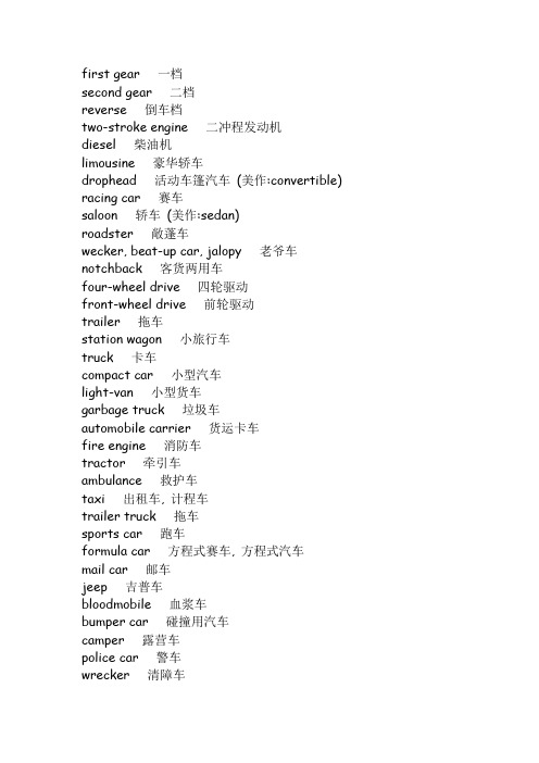
first gear 一档second gear 二档reverse 倒车档two-stroke engine 二冲程发动机diesel 柴油机limousine 豪华轿车drophead 活动车篷汽车(美作:convertible) racing car 赛车saloon 轿车(美作:sedan)roadster 敞蓬车wecker, beat-up car, jalopy 老爷车notchback 客货两用车four-wheel drive 四轮驱动front-wheel drive 前轮驱动trailer 拖车station wagon 小旅行车truck 卡车compact car 小型汽车light-van 小型货车garbage truck 垃圾车automobile carrier 货运卡车fire engine 消防车tractor 牵引车ambulance 救护车taxi 出租车, 计程车trailer truck 拖车sports car 跑车formula car 方程式赛车, 方程式汽车mail car 邮车jeep 吉普车bloodmobile 血浆车bumper car 碰撞用汽车camper 露营车police car 警车wrecker 清障车ambulance 急救车insulating tape 绝缘胶带jack 千斤顶can, jerrican 油桶fuel 燃油petrol 汽油(美作:gas)oil 油料lubrication, oiling 润滑油antifreeze 防冻液cooling water 冷却水antiskid 防滑装置tyre chain 防滑链(美作:tire chain)toolbox, tool kit 工具箱crank 摇把breakdown lorry, breakdown van 救援车辆(美作:tow car,tow truck)spare parts, spares 备件dipstick 油尺oil change 换油to vulcanize 硫化to inflate 充气tyre pressure 轮胎气压(美作:tire pressure)to fill the tank 加油petrol pump 加油泵(美作:gasoline pump)pump, air pump 气泵to adjust 整修to charge a battery, to recharge a battery 给蓄电池充电to decoke 脱硫(美作:to decarbonize)breakdown 故障mechanical failure 机械故障repair shop 维修车间to seize up 运转不畅accident 事故puncture, blowout 碰撞patch 修补to skid 打滑to knock 发出撞击声to tow, to take in tow 拖,拖曳accident insurance 事故保险insurance against theft 防盗保险fully comprehensive insurance 全险third-party insurance 第三方保险front wheel 前轮rear wheel 后轮tread 轮距chassis 底盘bodywork, body 车身rear window 后窗玻璃windscreen 挡风玻璃(美作:windshield)windscreen wiper 风档刮水器,风档雨雪刷(美作:windshield wiper)fender, wing, mudguard 挡泥板radiator grille 水箱wing mirror 后视镜bonnet 发动机盖(美作:hood)boot 行李箱(美作:trunk)roof rack, luggage rack 行李架license plate, number plate 车号牌wing 前翼子板hubcap 轮毂罩bumper 保险杠front blinker 前信号灯taillight, tail lamp 尾灯backup light, reversing light 倒车灯stoplight, stop lamp 刹车灯rear blinker 转弯指示灯trunk, boot 行李箱bumper 保险杠tailpipe 排气管。
江铃T系列欧三维修手册

江铃汽车T系列欧III维修手册
江铃汽车销售总公司服务工程管理部 2007.6.10
一统汽车检测设备
目录
第 1 章 概 述........................................................................................................1 1.1 JX493ZQ5A 发动机改变情况..............................................................1 1.1.1 欧III发动机与欧II发动机的差异...................................................1 1.1.2 JX493ZQ5A 发动机和JX493ZLQ3 发动机的差异 .....................2 1.2 欧Ⅲ发动机技术参数...............................................................................3
பைடு நூலகம்II
一统汽车检测设备
3.2 发动机电控单元EDC..............................................................................27 3.3 诊断接口.................................................................................................30
第 2 章 高压共轨系统..........................................................................................5 2.1 高压共轨系统概述...................................................................................5 2.2 高压共轨系统的基本组成........................................................................6 2.3 高压油泵...................................................................................................7 2.3.1 基本原理...........................................................................................7 2.3.2 装配要求...........................................................................................8 2.4 喷油器.......................................................................................................8 2.4.1 基本原理...........................................................................................8 2.4.2 装配要求.........................................................................................12 2.5 油轨.........................................................................................................12 2.6 高压喷射管路装置.................................................................................12 2.7 高压共轨系统装配顺序.........................................................................13 2.8 燃油滤清器.............................................................................................15 2.9 传感器.....................................................................................................15 2.9.1 曲轴位置传感器............................................................................15
第四章-进近离场
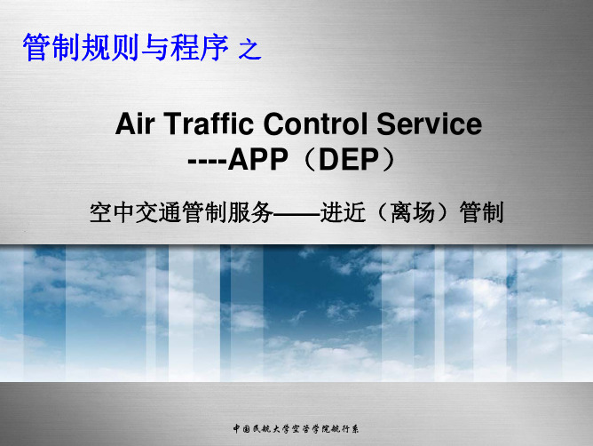
进近管制员
区域管制员
进近管制员
塔台管制员
受理 飞行计划 处理电报
发布 放行许可
批准 推出开车 滑行规则 跑道外等待 移交给本场 放行间隔 尾流间隔 起飞许可
标准离场航路 离场飞机指挥特点 离场指挥相关规定 所需配备间隔 飞行冲突调配 与区域管制移交协调
区域管制员职责 程序/雷达管制方式 程序/雷达间隔 区域指挥特点 飞行冲突调配 飞行情报服务 告警服务 与进近管制移交协调
中国民航大学空管学院航行系airtrafficcontrolserviceappdep空中交通管制服务进近离场管制管制规则与程序之中国民航大学空管学院航行系管制规则与程序飞行前准备起飞前准备滑行和起飞航路飞行着陆building发送落地许可落地条件尾流间隔标准进场航路雷达引导一般间隔目视进近和目视间排序飞行冲突调配区域管制员职责程序雷达管制方式程序雷达间隔区域指挥特点飞行冲突调配飞行情报服务告警服务与进近管制移交协调标准离场航路离场飞机指挥特点离场指挥相关规定所需配备间隔飞行冲突调配与区域管制移交协调批准推出开车滑行规则跑道外等待移交给本场放行间隔尾流间隔起飞许可发布放行许可受理飞行计划处理电报塔台管制员进近管制员区域管制员进近管制员塔台地面管制席管制员塔台管制员塔台放行席管制员飞行服务管制员中国民航大学空管学院航行系管制规则与程序一进近管制席负责对进离场的航空器及其空域范围内飞越航空器提供空中交通管制服务
管制规则与程序
中国民航大学空管学院航行系
管制规则与程序
X— DI LA D 32
LADIX—32D
中国民航大学空管学院航行系
平行跑道独立离场(DOC4444)
管制规则与程序
平行跑道可用于独立仪表离场方式的几种方式
a) 两条跑道同时只用于离场(独立离场); b) 一条跑道只用于离场,而另一条跑道离场进场混用(半混合 运行); c) 两条跑道均作为离场进场混用(混合运行)。
ULPI_v1_1
UTMI+ Low Pin Interface (ULPI)SpecificationRevision 1.1October 20, 2004Revision HistoryDate CommentRevision Issue0.9 November 12, 2003 Pre-release.1.0rc1 January 3, 2004 Introduce PHY interface “modes”.Update interface timings. Clarify 4-bit data clocking.Clarify sending of RX CMD’s and interrupts.Introduce AutoResume feature.Route int pin to data(3) during 6-pin Serial Mode.Explain VBUS thresholds.Add T&MT diagram and updated text.Add new section to explain how PHY is aborted by Link.Various clarifications.1.0rc2 January 13, 2004 Add block diagram.Tighten interface timing.Modify suspend protocol to more closely resemble UTMI.Add SPKR_L and SPKR_MIC to signal list and T&MTconnector.Various clarifications.1.0rc3 January 19, 2004 Specify that PHY must send RX CMD after Reset.Link + PHY clock startup time of no more than 5.6ms for aperipheral is now mandatory.PHY output delay reduced from 10ns to 9ns.Added link decision time numbers for low speed.Various Clarifications.1.0 February 2, 2004 1.0rc3 adopted as 1.0 release.1.1rc1 September 1, 2004 Various clarifications and fixes to hold time numbers, sendingRXCMDs, FsLsSerialMode, Vbus control and monitoring,Test_J and Tesk_K signalling, Low Power Mode,Hostdisconnect, ID detection, HS SOF packets, interrupts,Carkit Mode, interface protection, No SYNC/EOP mode,linestate filtering, and AutoResume.1.1rc2 October 4, 2004 Re-arranged text in section 3.8.7.3. Updated contributors list.1.1 October 20, 2004 1.1rc2 adopted as 1.1 release.The present Specification has been circulated for the sole benefit of legally-recognized Promoters, Adopters and Contributors of the Specification. All rights are expressly reserved, including but not limited to intellectual property rights under patents, trademarks, copyrights and trade secrets. The respective Promoter's, Adopter's or Contributor's agreement entered into by Promoters, Adopters and Contributors sets forth their conditions of use of the Specification.iiPromotersARC International Inc.Conexant Systems, Inc.Mentor Graphics CorporationPhilipsSMSCTransDimension, Inc.ContributorsVertenten PhilipsBartOkur PhilipsBatuhanBillAnderson MotorolaMcInerney TransDimensionBillBooker CypressBrianARCBelangerChrisKolb ARCChrisChrisSchell PhilipsChung Wing Yan PhilipsSrokaPhilipsDaveWang PhilipsDavidWooten TransDimensionDavidSMSCEricKawamotoPhilipsMackayFarranFrazier ConexantFrankFredRoberts SynopsysFarooqConexantHassanLee TransDimensionHyunParr MentorIanStandiford TransDimensionJayPhilipsTjiaJeromeMentorSaundersMarkMohamed Benromdhane ConexantSMSCMorganMonksISINabilTaklaTengstrand ARCPeterRamanand Mandayam ConexantDouglas MentorRobSaleemMohamed Synopsys(Author)ShaunReemeyer PhilipsCypressSimonNguyenSubramanyam Sankaran PhilipsTexasInstrumentsViningSueRemple QualcommTerryChen ConexantTimothyConexantChangVincentQuestions should be emailed to lpcwg@.iiiTable of Contents1.Introduction (1)1.1General (1)1.2Naming Convention (1)1.3Acronyms and Terms (1)1.4References (1)2.Generic Low Pin Interface (2)2.1General (2)2.2Signals (2)2.3Protocol (3)2.3.1Bus Ownership (3)2.3.2Transferring Data (3)2.3.3Aborting Data (4)3.UTMI+ Low Pin Interface (5)3.1General (5)3.2Signals (6)3.3Block Diagram (7)3.4Modes (9)3.5Power On and Reset (10)3.6Interrupt Event Notification (10)3.7Timing (11)3.7.1Clock (11)3.7.2Control and Data (13)3.8Synchronous Mode (15)3.8.1ULPI Command Bytes (15)3.8.2USB Packets (18)3.8.3Register Operations (30)3.8.4Aborting ULPI Transfers (37)3.8.5USB Operations (39)3.8.6Vbus Power Control (internal and external) (52)3.8.7OTG Operations (52)3.9Low Power Mode (55)3.9.1Data Line Definition For Low Power Mode (55)3.9.2Entering Low Power Mode (55)3.9.3Exiting Low Power Mode (56)3.9.4False Resume Rejection (57)3.10Full Speed / Low Speed Serial Mode (Optional) (58)3.10.1Data Line Definition For FsLsSerialMode (58)3.10.2Entering FsLsSerialMode (59)3.10.3Exiting FsLsSerialMode (60)3.11Carkit Mode (Optional) (61)3.12Safeguarding PHY Input Signals (62)4.Registers (65)4.1Register Map (65)4.2Immediate Register Set (67)4.2.1Vendor ID and Product ID (67)4.2.2Function Control (68)4.2.3Interface Control (69)4.2.4OTG Control (71)4.2.5USB Interrupt Enable Rising (72)4.2.6USB Interrupt Enable Falling (73)4.2.7USB Interrupt Status (74)4.2.8USB Interrupt Latch (75)4.2.9Debug (76)4.2.10Scratch Register (76)4.2.11Carkit Control (77)4.2.12Carkit Interrupt Delay (77)iv4.2.13Carkit Interrupt Enable (78)4.2.14Carkit Interrupt Status (78)4.2.15Carkit Interrupt Latch (79)4.2.16Carkit Pulse Control (79)4.2.17Transmit Positive Width (80)4.2.18Transmit Negative Width (80)4.2.19Receive Polarity Recovery (80)4.2.20Reserved (81)4.2.21Access Extended Register Set (81)4.2.22Vendor-specific (81)4.3Extended Register Set (81)4.4Register Settings for all Upstream and Downstream signalling modes (81)5.T&MT Connector (83)5.1General (83)5.2Daughter-card (UUT) Specification (83)vFiguresFigure 1 – LPI generic data bus ownership (3)Figure 2 – LPI generic data transmit followed by data receive (3)Figure 3 – Link asserts stp to halt receive data (4)Figure 4 – Creating a ULPI system using wrappers (5)Figure 5 – Block diagram of ULPI PHY (7)Figure 6 – Jitter measurement planes (12)Figure 7 – ULPI timing diagram (13)Figure 8 – Clocking of 4-bit data interface compared to 8-bit interface (14)Figure 9 – Sending of RX CMD (17)Figure 10 – USB data transmit (NOPID) (18)Figure 11 – USB data transmit (PID) (19)Figure 12 – PHY drives an RX CMD to indicate EOP (FS/LS LineState timing not to scale) (20)Figure 13 – Forcing a full/low speed USB transmit error (timing not to scale) (21)Figure 14 – USB receive while dir was previously low (22)Figure 15 – USB receive while dir was previously high (23)Figure 16 – USB receive error detected mid-packet (24)Figure 17 – USB receive error during the last byte (25)Figure 18 – USB HS, FS, and LS bit lengths with respect to clock (26)Figure 19 – HS transmit-to-transmit packet timing (29)Figure 20 – HS receive-to-transmit packet timing (29)Figure 21 – Register write (30)Figure 22 – Register read (31)Figure 23 – Register read or write aborted by USB receive during TX CMD byte (31)Figure 24 – Register read turnaround cycle or Register write data cycle aborted by USB receive (32)Figure 25 – USB receive in same cycle as register read data. USB receive is delayed (33)Figure 26 – Register read followed immediately by a USB receive (33)Figure 27 – Register write followed immediately by a USB receive during stp assertion (34)Figure 28 – Register read followed by a USB receive (34)Figure 29 – Extended register write (35)Figure 30 – Extended register read (35)Figure 31 – Extended register read aborted by USB receive during extended address cycle (36)Figure 32 – PHY aborted by Link asserting stp. Link performs register write or USB transmit (37)Figure 33 – PHY aborted by Link asserting stp. Link performs register read (38)Figure 34 – Link aborts PHY. Link fails to drive a TX CMD. PHY re-asserts dir (38)Figure 35 – Hi-Speed Detection Handshake (Chirp) sequence (timing not to scale) (40)Figure 36 – Preamble sequence (D+/D- timing not to scale) (41)Figure 37 – LS Suspend and Resume (timing not to scale) (43)Figure 38 – FS Suspend and Resume (timing not to scale) (44)Figure 39 – HS Suspend and Resume (timing not to scale) (46)Figure 40 – Low Speed Remote Wake-Up from Low Power Mode (timing not to scale) (47)Figure 41 – Full Speed Remote Wake-Up from Low Power Mode (timing not to scale) (48)Figure 42 – Hi-Speed Remote Wake-Up from Low Power Mode (timing not to scale) (49)Figure 43 – Automatic resume signalling (timing not to scale) (50)Figure 44 – USB packet transmit when OpMode is set to 11b (51)Figure 45 – RX CMD V A_VBUS_VLD ≤Vbus indication source (54)Figure 46 – Entering low power mode (55)Figure 47 – Exiting low power mode when PHY provides output clock (56)Figure 48 – Exiting low power mode when Link provides input clock (56)Figure 49 – PHY stays in Low Power Mode when stp de-asserts before clock starts (57)Figure 50 – PHY re-enters Low Power Mode when stp de-asserts before dir de-asserts (57)Figure 51 – Interface behaviour when entering Serial Mode and clock is powered down (59)Figure 52 – Interface behaviour when entering Serial Mode and clock remains powered (59)Figure 53 – Interface behaviour when exiting Serial Mode and clock is not running (60)Figure 54 – Interface behaviour when exiting Serial Mode and clock is running (60)Figure 55 – PHY interface protected when the clock is running (62)Figure 56 – Power up sequence when PHY powers up before the link. Interface is protected (63)Figure 57 – PHY automatically exits Low Power Mode with interface protected (63)Figure 58 – Link resumes driving ULPI bus and asserts stp because clock is not running (64)viFigure 59 – Power up sequence when link powers up before PHY (ULPI 1.0 compliant links) (64)Figure 60 – Recommended daughter-card configuration (not to scale) (83)viiTablesTable 1 – LPI generic interface signals (2)Table 2 – PHY interface signals (6)Table 3 – Mode summary (9)Table 4 – Clock timing parameters (11)Table 5 – ULPI interface timing (13)Table 6 – Transmit Command (TX CMD) byte format (15)Table 7 – Receive Command (RX CMD) byte format (16)Table 8 – USB specification inter-packet timings (26)Table 9 – PHY pipeline delays (27)Table 10 – Link decision times (28)Table 11 – OTG Control Register power control bits (52)Table 12 – Vbus comparator thresholds (52)Table 13 – RX CMD VbusValid over-current conditions (53)Table 14 – Vbus indicators in the RX CMD required for typical applications (54)Table 15 – Interface signal mapping during Low Power Mode (55)Table 16 – Serial Mode signal mapping for 6-pin FsLsSerialMode (58)Table 17 – Serial Mode signal mapping for 3-pin FsLsSerialMode (58)Table 18 – Carkit signal mapping (61)Table 19 – Register map (66)Table 20 – Register access legend (67)Table 21 – Vendor ID and Product ID register description (67)Table 22 – Function Control register (68)Table 23 – Interface Control register (70)Table 24 – OTG Control register (71)Table 25 – USB Interrupt Enable Rising register (72)Table 26 – USB Interrupt Enable Falling register (73)Table 27 – USB Interrupt Status register (74)Table 28 – USB Interrupt Latch register (75)Table 29 – Rules for setting Interrupt Latch register bits (75)Table 30 – Debug register (76)Table 31 – Scratch register (76)Table 32 – Carkit Control Register (77)Table 33 – Carkit Interrupt Delay register (77)Table 34 – Carkit Interrupt Enable register (78)Table 35 – Carkit Interrupt Status Register (78)Table 36 – Carkit Interrupt Latch register (79)Table 37 – Carkit Pulse Control (79)Table 38 – Transmit Positive Width (80)Table 39 – Transmit Negative Width (80)Table 40 – Receive Polarity Recovery (81)Table 41 – Upstream and downstream signalling modes (82)Table 42 – T&MT connector pin view (84)Table 43 – T&MT connector pin allocation (84)Table 44 – T&MT pin description (85)viii1. Introduction1.1 GeneralThis specification defines a generic PHY interface in Chapter 2.In Chapter 3, the generic interface is applied to the UTMI+ protocol, reducing the pin count for discrete USB transceiver implementations supporting On-The-Go, host, and peripheral application spaces.Convention1.2 NamingEmphasis is placed on normal descriptive text using underlined Arial font, e.g. must.Signal names are represented using the lowercase bold Arial font, e.g. clk.Registers are represented using initial caps, bold Arial font, e.g. OTG Control.Register bits are represented using initial caps, bold italic Arial font, e.g. USB Interrupt Enable Falling. 1.3 Acronyms and TermsA-device Device with a Standard-A or Mini-A plug inserted into its receptacleB-device Device with a Standard-B or Mini-B plug inserted into its receptacleDeviceDRD Dual-RoleFPGA Field Programmable Gate ArraySpeedFS FullHNP Host Negotiation ProtocolHS Hi-SpeedLink ASIC, SIE, or FPGA that connects to an ULPI transceiverLPI Low Pin InterfaceSpeedLS LowOTG On-The-GoPHY Physical Layer (Transceiver)PLL Phase Locked LoopSE0 Single Ended ZeroSIE Serial Interface EngineSRP Session Request ProtocolT&MT Transceiver and Macrocell TesterULPI UTMI+ Low Pin InterfaceUSB Universal Serial BusUSB-IF USB Implementers ForumUTMI USB 2.0 Transceiver Macrocell InteraceUUT Unit Under Test1.4 References[Ref 1] Universal Serial Bus Specification, Revision 2.0[Ref 2] On-The-Go Supplement to the USB 2.0 Specification, Revision 1.0a[Ref 3] USB 2.0 Transceiver Macrocell Interface (UTMI) Specification, v1.05[Ref 4] UTMI+ Specification, Revision 1.0[Ref 5] CEA-2011, OTG Transceiver Specification[Ref 6] CEA-936A, Mini-USB Analog Carkit Interface Specification[Ref 7] USB 2.0 Transceiver and Macrocell Tester (T&MT) Interface Specification, Version 1.212. Generic Low Pin Interface2.1 GeneralThis section describes a generic low pin interface (LPI) between a Link and a PHY. Interface signals are defined and the basic communication protocol is described. The generic interface can be used as a common starting point for defining multiple application-specific interfaces.Chapter 3 defines the UTMI+ Low Pin Interface (ULPI), which is based on the generic interface described here. For ULPI implementations, the definitions in chapter 3 over-ride anything defined in chapter 2.2.2 SignalsThe LPI transceiver interface signals are described in Table 1. The interface described here is generic, and can be used to transport many different data types. Depending on the application, the data stream can be used to transmit and receive packets, access a register set, generate interrupts, and even redefine the interface itself. All interface signals are synchronous when clock is toggling, and asynchronous when clock is not toggling. Data stream definition is application-specific and should be explicitly defined for each application space for inter-operability.Control signals dir, stp, and nxt are specified with the assumption that the PHY is the master of the data bus. If required, an implementation can define the Link as the master. If the Link is the master of the interface, the control signal direction and protocol must be reversed.Signal Direction DescriptionPHY Interfaceclock I/O Interface clock. Both directions are allowed. All interface signals are synchronous to clock.data I/O Bi-directional data bus, driven low by the Link during idle. Bus ownership is determined by dir. The Link and PHY initiate data transfers by driving a non-zero pattern onto the data bus. LPI defines interface timing for single-edge data transfers with respect to rising edge of clock. An implementation may optionally define double-edge data transfers with respect to both rising and falling edges of clock.dir OUT Direction. Controls the direction of the data bus. When the PHY has data to transfer to the Link, it drives dir high to take ownership of the bus. When the PHY has no data to transfer it drives dir low and monitors the bus for Link activity. The PHY pulls dir high whenever the interface cannot accept data from the Link. For example, when the internal PHY PLL is not stable.stp IN Stop. The Link asserts this signal for 1 clock cycle to stop the data stream currently on the bus. If the Link is sending data to the PHY, stp indicates the last byte of data was on the bus in the previous cycle. If the PHY is sending data to the Link, stp forces the PHY to end its transfer, de-assert dir and relinquish control of the the data bus to the Link.nxt OUT Next. The PHY asserts this signal to throttle the data. When the Link is sending data to the PHY, nxt indicates when the current byte has been accepted by the PHY. The Link places the next byte on the data bus in the following clock cycle. When the PHY is sending data to the Link, nxt indicates when a new byte is available for the Link to consume.Table 1 – LPI generic interface signals22.3 ProtocolOwnership2.3.1 BusThe PHY is the master of the LPI bi-directional data bus. Ownership of the data bus is determined by the dir signal from the PHY, as shown in Figure 1. When dir is low, the Link can drive data on the bus. When dir is high, the PHY can drive data on the bus. A change in dir causes a turnaround cycle on the bus during which, neither Link nor PHY can drive the bus. Data during the turnaround cycle is undefined and must be ignored by both Link and PHY.The dir signal can be used to directly control the data output buffers of both PHY and Link.Figure 1 – LPI generic data bus ownershipData2.3.2 TransferringAs shown in the first half of Figure 2, the Link continuously drives the data bus to 00h during idle. The Link transmits data to the PHY by driving a non-zero value on the data bus. To signal the end of data transmission, the Link asserts stp in the cycle following the last data byte.In the second half of Figure 2, the Link receives data when the PHY asserts dir. The PHY asserts dir only when it has data to send to the Link, and keeps dir low at all other times. The PHY drives data to the Link after the turnaround cycle.The nxt signal can be used by the PHY to throttle the data during transmit and receive. During transmit, nxt may be asserted in the same cycle that the Link asserts stp.Figure 2 – LPI generic data transmit followed by data receive2.3.3 AbortingDataThe PHY can assert dir to interrupt any data being transmitted by the Link. If the Link needs to interrupt data being received from the PHY, it asserts stp for one clock cycle, as shown in Figure 3. This causes the PHY to unconditionally1 de-assert dir and accept a complete data transmit from the Link. The PHY may re-assert dir again only when the data transmit from the Link has completed.Figure 3 – Link asserts stp to halt receive data1 The PHY will not de-assert dir if the ULPI interface is not usable. For example, if the internal PLL is not stable.3. UTMI+ Low Pin Interface3.1 GeneralThis section describes how any UTMI+ core can be wrapped to convert it to the smaller LPI interface. The generic interface described in chapter 2 is used as a starting point. This section always over-rides anything stated in chapter 2. While this specification details support of UTMI+ Level 3, PHY implementers may choose to support any of the Levels defined in UTMI+.ULPI defines a PHY to Link interface of 8 or 12 signals that allows a lower pin count option for connecting to an external transceiver that may be based on the UTMI+ specification. The pin count reduction is achieved by having relatively static UTMI+ signals be accessed through registers and by providing a bi-directional data bus that carries USB data and provides a means of accessing register data on the ULPI transceiver.This specification relies on concepts and terminology that are defined in the UTMI+ specification [Ref 4]. Specifically, if a ULPI PHY design is based on an internal UTMI+ core, then that core must implement the following UTMI+ features.Linestate must accurately reflect D+/D- to within 2-3 clocks. It is up to individual Link designers to use Linestate to time bus events.Filtering to prevent spurious SE0/SE1 states appearing on Linestate due to skew between D+ and D-. Filtering of 14 clock cycles is required in Low Speed, and 2 clock cycles in Full Speed and Hi-Speed modes.The PHY must internally block the USB receive path during transmit. The receive path can be unblocked when the internal Squelch (HS) or SE0-to-J (FS/LS) is seen.TxReady must be used for all types of data transmitted, including Chirp.Due to noise on the USB, it is possible that RxActive asserts and then de-asserts without any valid data being received, and RxValid will not assert. The Link should operate normally with these data-less RxActive assertions.As shown in Figure 4, a PHY or Link based on this specification can be implemented as an almost transparent wrapper around existing UTMI+ IP cores, preserving the original UTMI+ packet timing, while reducing pin count and leaving all functionality intact. This should not be taken to imply that other implementations are not possible.Figure 4 – Creating a ULPI system using wrappers3.2 SignalsTable 2 describes the ULPI interface on the PHY. The PHY is always the master of the ULPI bus. USB and Miscellaneous signals may vary with each implementation and are given only as a guide to PHY designers.Signal Direction DescriptionPHY Interfaceclock I/O Interface clock. The PHY must be capable of providing a 60MHz output clock. Support for an input 60MHz clock is optional. If the PHY supports both clock directions, it must not use the ULPI control and data signals for setting the clock direction.Data bus. Driven to 00h by the Link when the ULPI bus is idle. Two bus widths are allowed:• 8-bit data timed on rising edge of clock.data I/O• (Optional) 4-bit data timed on rising and falling edges of clock.dir OUT Controls the direction of the data bus2. The PHY pulls dir high whenever the interface cannot accept data from the Link. For example, when the internal PLL is not stable. This applies whether Link or PHY is the clock source.stp IN The Link must assert stp to signal the end of a USB transmit packet or a register write operation, and optionally to stop any receive. The stp signal must be asserted in the cycle after the last data byte is presented on the bus.nxt OUT The PHY asserts nxt to throttle all data types, except register read data and the RX CMD. Identical to RxValid during USB receive, and TxReady during USB transmit. The PHY also asserts nxt and dir simultaneously to indicate USB receive activity (RxActive), if dir was previously low. The PHY is not allowed to assert nxt during the first cycle of the TX CMD driven by the Link.USB InterfaceD+ I/O D+ pin of the USB cable. Required.D- I/O D- pin of the USB cable. Required.ID IN ID pin of the USB cable. Required for OTG-capable PHY’s.VBUS I/O V BUS pin of the USB cable. Required for OTG-capable PHY’s. Required for driving V BUS and the V BUS comparators.MiscellaneousXI IN Crystal input pin. Vendors should specify supported crystal frequencies. XO OUT Crystal output pin.C+ I/O Positive terminal of charge pump capacitor.C- I/O Negative terminal of charge pump capacitor.SPKR_L IN Optional Carkit left/mono speaker input signal.SPKR_MIC I/O Optional Carkit right speaker input or microphone output signal.RBIAS I/O Bias current resistor.Table 2 – PHY interface signals2 UTMI+ wrapper developers should note that data bus control has been reversed from UTMI to ensure that USB data reception is not interrupted by the Link.3.3 BlockDiagramAn example block diagram of a ULPI PHY is shown in Figure 5. This example is based on an internal UTMI+ Level 3 core [Ref 4], which can interface to peripheral, host, and On-The-Go Link cores. A description of each major block is given below.ULPI InterfaceUSBCableChargePumpCapacitor Figure 5 – Block diagram of ULPI PHYUTMI+ Level 3 PHY coreThe ULPI PHY may contain a core that is compliant to any UTMI+ level [Ref 4]. Signals for 16-bit data buses are not supported in ULPI. While Figure 5 shows the typical blocks for a Level 3 UTMI+ core, the PHY vendor must specify the intended UTMI+ level, and provide the functionality necessary for compliance to that level.ULPI PHY WrapperThe ULPI PHY wrapper of Figure 5 reduces the UTMI+ interface to the Low Pin Interface described in this document. All signals shown on the UTMI+ Level 3 PHY core are reduced to the ULPI interface signals clock, data, dir, stp, and nxt. The Register Map stores the relatively static signals of the UTMI+ interface. Crystal Oscillator and PLLWhen a crystal is attached to the PHY, the internal clock(s) and the external 60MHz interface clock are generated from the internal PLL. When no crystal is attached, the PHY may optionally generate the internal clock(s) from an input 60MHz clock provided by the Link.General BiasingInternal analog circuits require an accurate bias current. This is typically generated using an external, accurate reference resistor.DrvVbusExternal and ExternalVbusIndicatorThe PHY may optionally control an external VBUS power source via the optional pin DrvVbusExternal. For example, the external supply could be a charge pump or 5V power supply controlled using a power switch. The external supply is controlled by the DrvVbus and the optional DrvVbusExternal bits in the OTG Control register. The polarity of the DrvVbusExternal output pin is implementation dependent.If control of an external VBUS source is provided the PHY may optionally provide for a VBUS power source feed back signal on the optional pin ExternalVbusIndicator. If this pin is provided, the use of the pin is defined by the optional control bits in the OTG Control and Interface Control registers. See Section 3.8.6.3 for further detail.Power-On-ResetA power-on-reset circuit must be provided in the PHY. When power is first applied to the PHY, the power-on-reset will reset all circuitry and leave the ULPI interface in a usable state.Carkit OptionThe PHY may optionally support Carkit Mode [Ref 6]. While in Carkit Mode, the PHY routes speaker and microphone signals between the Link and the USB cable. In carkit mono mode, SPKR_L inputs a mono speaker signal and SPKR_MIC outputs the microphone signal, MIC. In carkit stereo mode, SPKR_L inputs the left speaker signal, and SPKR_MIC inputs the right speaker signal, SPKR_R.3.4 ModesThe ULPI interface can operate in one of five independent modes listed in Table 3. The interface is in Synchronous Mode by default. Other modes are enabled by bits in the Function Control and Interface Control registers. In Synchronous Mode, the data bus carries commands and data. In other modes, the data pins are redefined with different functionality. Synchronous Mode and Low Power Mode are mandatory.Mode Name Mode DescriptionSynchronous Mode This is the normal mode of operation. The clock is running and is stablewith the characteristics defined in section 3.6. The ULPI interface carriescommands and data that are synchronous to clock.Low Power Mode The PHY is powered down with the clock stopped. The PHY keeps dirasserted, and the data bus is redefined to carry LineState and interrupts.See section 3.9 for more information.6-pin FS/LS Serial Mode (optional) The data bus is redefined to 6-pin serial mode, including 6 pins to transmit and receive serial USB data, and 1 pin to signal interrupt events. The clock can be enabled or disabled. This mode is valid only for implementations with an 8-bit data bus. See section 3.10 for more information.3-pin FS/LS Serial Mode (optional) The data bus is redefined to 3-pin serial mode, including 3 pins to transmit and receive serial USB data, and 1 pin to signal interrupt events. The clock can be enabled or disabled. See section 3.10 for more information.Carkit Mode (optional) The data bus is redefined to Carkit mode [Ref 6], including 2 pins for serial UART data, and 1 pin to signal interrupt events. The clock may optionally be stopped. See section 3.11 for more information.Table 3 – Mode summary。
车型数据库
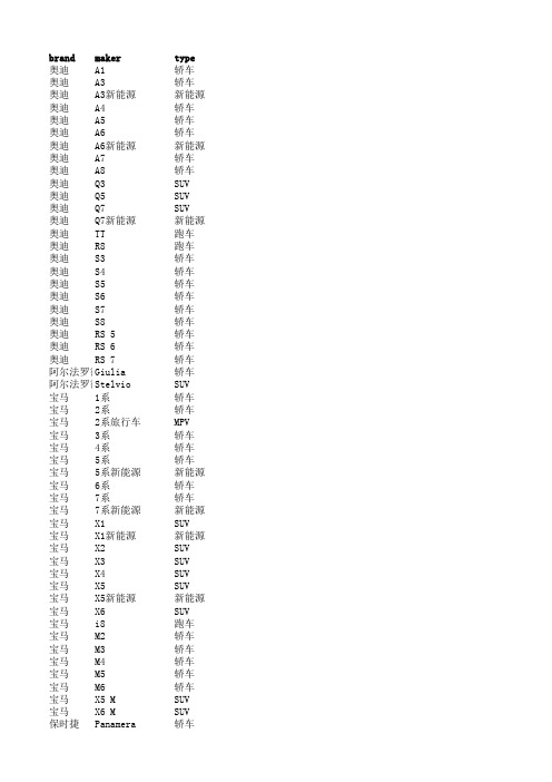
brand maker type 奥迪A1轿车奥迪A3轿车奥迪A3新能源新能源奥迪A4轿车奥迪A5轿车奥迪A6轿车奥迪A6新能源新能源奥迪A7轿车奥迪A8轿车奥迪Q3SUV奥迪Q5SUV奥迪Q7SUV奥迪Q7新能源新能源奥迪TT跑车奥迪R8跑车奥迪S3轿车奥迪S4轿车奥迪S5轿车奥迪S6轿车奥迪S7轿车奥迪S8轿车奥迪RS 5轿车奥迪RS 6轿车奥迪RS 7轿车阿尔法罗密欧Giulia轿车Stelvio SUV阿尔法罗密欧宝马1系轿车宝马2系轿车宝马2系旅行车MPV宝马3系轿车宝马4系轿车宝马5系轿车宝马5系新能源新能源宝马6系轿车宝马7系轿车宝马7系新能源新能源宝马X1SUV宝马X1新能源新能源宝马X2SUV宝马X3SUV宝马X4SUV宝马X5SUV宝马X5新能源新能源宝马X6SUV宝马i8跑车宝马M2轿车宝马M3轿车宝马M4轿车宝马M5轿车宝马M6轿车宝马X5 M SUV宝马X6 M SUV保时捷Panamera轿车保时捷Panamera新能源新能源保时捷Macan SUV保时捷Cayenne SUV保时捷Cayenne新能源新能源保时捷718跑车保时捷911跑车保时捷Boxster跑车保时捷Cayman跑车奔驰A级轿车奔驰B级轿车奔驰C级轿车奔驰E级轿车奔驰S级轿车奔驰CLA级轿车奔驰CLS级轿车奔驰GLC级SUV奔驰GLK级SUV奔驰GLE级SUV奔驰M级SUV奔驰G级SUV奔驰GL级SUV奔驰GLS级SUV奔驰V级MPV奔驰V级MPV奔驰R级MPV奔驰SLK级跑车奔驰SLC级跑车奔驰SL级跑车奔驰迈巴赫S级轿车奔驰A级AMG轿车奔驰C级AMG轿车奔驰E级AMG轿车奔驰S级AMG轿车奔驰GLA级AMG SUV奔驰GLC级AMG SUV奔驰GLE级AMG SUV奔驰CLS级AMG轿车奔驰AMG GT跑车本田杰德MPV本田思域轿车本田哥瑞轿车本田竞瑞轿车本田思铂睿轿车本田XR-V SUV本田CR-V SUV本田UR-V SUV本田艾力绅MPV本田飞度轿车本田锋范轿车本田凌派轿车本田雅阁轿车本田缤智SUV本田冠道SUV本田奥德赛MPV本田歌诗图SUV比亚迪秦新能源比亚迪宋SUV比亚迪宋新能源新能源比亚迪宋MAX MPV比亚迪唐SUV比亚迪唐新能源新能源比亚迪e5新能源比亚迪S7SUV比亚迪M6MPV比亚迪速锐轿车比亚迪G5轿车比亚迪F3轿车比亚迪F0轿车标致301轿车标致308轿车标致308S轿车标致408轿车标致2008SUV标致3008SUV标致4008SUV标致5008SUV标致508轿车标致RCZ跑车别克VELITE 5轿车别克凯越轿车别克威朗轿车别克英朗轿车别克阅朗轿车别克君威轿车别克君越轿车别克昂科拉SUV别克昂科威SUV别克GL6MPV别克GL8MPV别克昂科雷SUV宾利慕尚轿车宾利飞驰轿车宾利添越SUV宾利欧陆GT跑车大众POLO轿车大众捷达轿车大众宝来轿车大众高尔夫轿车大众速腾轿车大众桑塔纳轿车大众朗行轿车大众朗逸轿车大众蔚领轿车大众朗境轿车大众凌渡轿车大众迈腾轿车大众CC轿车大众帕萨特轿车大众辉昂轿车大众途安MPV 大众夏朗MPV 大众高尔夫嘉旅MPV 大众途观SUV 大众途昂SUV 大众探歌SUV 大众途锐SUV 大众Tiguan SUV 大众甲壳虫轿车大众蔚揽轿车大众up!轿车大众迈特威MPV 大众凯路威MPV 大众尚酷轿车道奇酷威SUV 法拉利加利福尼亚T跑车法拉利F12berlinetta跑车法拉利F430跑车法拉利360跑车法拉利FF跑车法拉利599跑车法拉利458跑车法拉利488跑车法拉利812 Superfast跑车丰田致炫轿车丰田致享轿车丰田雷凌轿车丰田卡罗拉轿车丰田威驰轿车丰田花冠轿车丰田皇冠轿车丰田凯美瑞轿车丰田锐志轿车丰田RAV4荣放SUV 丰田汉兰达SUV 丰田普拉多SUV 丰田兰德酷路泽SUV 丰田逸致MPV 丰田埃尔法MPV 丰田普瑞维亚MPV 丰田塞纳MPV 丰田86轿车丰田坦途SUV 福特嘉年华轿车福特福克斯轿车福特蒙迪欧轿车福特致胜轿车福特金牛座轿车福特翼博SUV 福特翼虎SUV 福特锐界SUV 福特撼路者SUV 福特途睿欧MPV福特全顺MPV 福特探险者SUV 福特F150SUV 福特野马跑车福特E350MPV GMC SAVANA MPV 广汽传祺GA4轿车广汽传祺GA5轿车广汽传祺GA6轿车广汽传祺GS3SUV 广汽传祺GS4SUV 广汽传祺GS7SUV 广汽传祺GS8SUV 广汽传祺GM8MPV 哈弗H1SUV 哈弗H2SUV 哈弗H4SUV 哈弗H5SUV 哈弗H6SUV 哈弗H7SUV 哈弗H8SUV 哈弗H9SUV 悍马H2SUV 悍马H3SUV 红旗H5轿车红旗H7轿车Jeep自由侠SUV Jeep指南者SUV Jeep大指挥官SUV Jeep自由光SUV Jeep指挥官SUV Jeep牧马人SUV Jeep大切诺基SUV 吉利帝豪轿车吉利博瑞轿车吉利博越SUV 吉利金刚轿车吉利帝豪GL轿车吉利帝豪GS SUV 吉利远景SUV SUV 捷豹XE轿车捷豹XF轿车捷豹XJ轿车捷豹F-PACE SUV 捷豹I-PACE SUV 捷豹F-TYPE跑车凯迪拉克ATS轿车凯迪拉克XTS轿车凯迪拉克CT6轿车凯迪拉克XT5SUV 凯迪拉克SRX SUV 凯迪拉克凯雷德SUV 克莱斯勒300C轿车克莱斯勒大捷龙MPV兰博基尼Urus跑车兰博基尼Huracun跑车兰博基尼Aventador跑车劳斯莱斯幻影轿车劳斯莱斯古思特轿车劳斯莱斯魅影轿车劳斯莱斯曜影轿车雷克萨斯CT轿车雷克萨斯IS轿车雷克萨斯ES轿车雷克萨斯GS轿车雷克萨斯LS轿车雷克萨斯NX SUV 雷克萨斯GX SUV 雷克萨斯RX SUV 雷克萨斯LX SUV 雷克萨斯LC轿车雷克萨斯RC跑车雷克萨斯RC F跑车雷诺科雷傲SUV 雷诺科雷嘉SUV 雷诺卡缤SUV 雷诺Espacce MPV 林肯MKZ轿车林肯MKC SUV 林肯MKX SUV 林肯大陆轿车林肯领航员SUV 领克领克01SUV 领克领克02SUV 路虎发现神行SUV 路虎极光SUV 路虎星脉SUV 路虎发现神行SUV 路虎揽胜SUV 路虎揽胜运动版SUV 路虎卫士SUV 路虎神行者2SUV MINI MINI轿车MINI CLUBMAN轿车MINI COUNTRYMAN SUV MINI JCW MINI轿车MINI JCW CLUBMAN轿车MINI JCW COUNTRYMAN轿车马自达昂克赛拉轿车马自达阿特兹轿车马自达CX-3SUV 马自达CX-4SUV 马自达CX-5SUV 马自达MX-5跑车马自达马自达6轿车马自达马自达8MPV 马自达睿翼轿车玛莎拉蒂Ghibli轿车玛莎拉蒂总裁轿车玛莎拉蒂Levante SUV玛莎拉蒂GranTurismo跑车玛莎拉蒂GranCabrio跑车迈凯伦540C跑车迈凯伦570跑车迈凯伦12C跑车迈凯伦625C跑车迈凯伦675LT跑车迈凯伦650S跑车迈凯伦P1跑车迈凯伦720S跑车迈凯伦600LT跑车名爵名爵3轿车名爵名爵3SW轿车名爵名爵6轿车名爵锐腾SUV名爵锐行轿车名爵名爵ZS SUV奇瑞QQ轿车奇瑞艾瑞泽5轿车奇瑞艾瑞泽7轿车奇瑞瑞虎3SUV奇瑞瑞虎3新能源新能源奇瑞瑞虎5SUV奇瑞瑞虎7SUV奇瑞瑞虎8SUV奇瑞eq1新能源奇瑞艾瑞泽5e新能源起亚KX CROSS轿车起亚焕驰轿车起亚K2轿车起亚K3轿车起亚K4轿车起亚K5轿车起亚凯绅轿车起亚福瑞迪轿车起亚KX3SUV起亚KX5SUV起亚KX7SUV起亚智跑SUV起亚K9轿车起亚索兰托SUV起亚凯尊轿车起亚佳乐MPV起亚嘉华MPV起亚霸锐SUV日产玛驰轿车日产骊威轿车日产骐达轿车日产轩逸轿车日产阳光轿车日产蓝鸟轿车日产天籁轿车日产西玛轿车日产劲客SUV日产逍客SUV日产途达SUV日产奇骏SUV日产楼兰SUV日产NV200MPV日产途乐SUV日产纳瓦拉SUV日产贵士MPV日产GT-R跑车荣威350轿车荣威360轿车荣威550轿车荣威e550新能源荣威950轿车荣威e950新能源荣威Ei5新能源荣威Ei6新能源荣威i6轿车荣威RX3SUV荣威RX5SUV荣威Erx5新能源smart smart fortwo轿车smart smart forfour轿车三菱劲炫ASX SUV三菱欧蓝德SUV三菱帕杰罗SUV三菱帕杰罗劲畅SUV三菱翼神轿车斯巴鲁森林人SUV斯巴鲁XV SUV斯巴鲁傲虎SUV斯巴鲁力狮轿车斯巴鲁翼豹轿车斯巴鲁BRZ轿车斯柯达晶锐轿车斯柯达明锐轿车斯柯达昕动轿车斯柯达速派轿车斯柯达昊锐轿车斯柯达柯珞克SUV斯柯达柯米克SUV斯柯达柯迪亚克SUV斯柯达Yeti SUV特斯拉Model S新能源特斯拉Model X新能源腾势腾势新能源WEY VV5SUV WEY P8SUV WEY VV7SUV蔚来ES8新能源沃尔沃S40轿车沃尔沃S60轿车沃尔沃S60新能源新能源沃尔沃S80轿车沃尔沃S90轿车沃尔沃XC40SUV沃尔沃XC60SUV沃尔沃XC90SUV沃尔沃V40轿车沃尔沃V60轿车沃尔沃V90轿车现代瑞纳轿车现代瑞奕轿车现代悦纳轿车现代悦动轿车现代朗动轿车现代领动轿车现代名图轿车现代索纳塔轿车现代昂系诺SUV现代ix25SUV现代途胜SUV现代ix35SUV现代胜达SUV现代飞思轿车现代雅尊轿车现代捷恩斯轿车现代劳恩斯酷派轿车雪佛兰赛欧轿车雪佛兰乐风RV轿车雪佛兰科鲁兹轿车雪佛兰科沃兹轿车雪佛兰迈锐宝轿车雪佛兰迈锐宝XL轿车雪佛兰爱唯欧轿车雪佛兰创酷SUV雪佛兰探界者SUV雪佛兰科帕奇SUV雪佛兰科迈罗跑车雪铁龙C4L轿车雪铁龙世嘉轿车雪铁龙C3-XR SUV雪铁龙C5轿车雪铁龙C6轿车雪铁龙爱丽舍轿车雪铁龙天逸C5 AIRCROSS SUV雪铁龙C4 Aircross SUV雪铁龙C4 PICASSO MPV英菲尼迪Q50轿车英菲尼迪Q50L轿车英菲尼迪Q70轿车英菲尼迪QX50SUV英菲尼迪QX30SUV英菲尼迪QX60SUV英菲尼迪QX70SUV英菲尼迪QX80SUV英菲尼迪Q60跑车。
品牌Club Car型号TN011产品说明书

© Alltrax Inc. 2007 All Rights Reserved Richard CsukCustomer/Technical Service ManagerAlltrax Inc September 4, 2007Technical Note 011: Resetting the Club Car OBCOverviewClub Car uses an On Board Computer (or OBC) to monitor and control various functions of their carts. It functions as a Go/No Go control for the charging and drive systems. If the OBC detects a problem in either the charging or drive system, it will shut that feature off. When the fault clears, the OBC is supposed to re-enable that system.Sometimes, the OBC will not clear a fault. When this happens, it can cause the Alltrax controller to not power up or the solenoid will not engage. The act of removing the controller from the cart will cause a soft reset of the OBC when the battery power is removed. With the battery power removed, the internal capacitors discharge and clear any faults. When the new controller is installed, everything works fine and the controller is considered bad, even though the problem was in the OBC.It is possible to manually reset the OBC to verify that it is not the problem. In any situation where the controller did not obviously fail, but it just stopped the OBC needs to be reset first. The reset process is easy to do, but can take a fair amount of time. Resetting the OBCTo reset the OBC the following must be done in this order:•Key Switch to Off•Forward/Reverse to Neutral•Tow/Run Switch to Tow•Disconnect the Battery NEGATIVE (–) wire from the Battery Minus terminal on the batterypack.•Put the Tow/Run to Run•Forward/Reverse Switch to Reverse•Key Switch to On•Lock the throttle pedal downThe reverse buzzer will sound and go off in about 30 seconds. Leave the cart like that for 5 min to cause the OBC to reset.To reconnect the OBC back into the system:•Key Switch to Off•Forward/Reverse Switch to Neutral•Tow/Run switch to Tow•Reconnect the Batt – wire to the battery minus terminal on the battery pack.Once the OBC has been reset, the cart can be troubleshot. There is always a chance the OBC has completely failed and the reset process will not fix the problem. Consult your Club Car manuals or contact Alltrax for more troubleshooting of vehicles with an OBC.Any questions? Please contact Alltrax Technical Support Hotline or send email to *******************Today, Power Conversion Engineering (PCE) is the research and development armof ALLTRAX and provides the industry a powerful and robust controller to meet all“The company was founded at the track”。
123Scan2操作指南

Motorola 123Scan2简明操作指南V 1.01 | P a g e目录启动 (4)一创建新的配置文件 (5)1选择扫描枪与PC的连接方式 (5)2选择扫描枪型号 (6)3参数设置 (7)1)名称和注释 (7)2)数据线连接方式 (7)3)条码码制选择 (9)4)数据格式化设置 (10)4-1)创建新的规则 (12)4-2)将规则保存到数据库 (14)4-3)从数据库中添加规则 (14)5)通用设置 (15)6)打印选项 (16)7)加载和打印 (17)7-1)将配置文件保存到电脑 (18)7-2)打印出设置条码 (18)7-3)加载设置到连接的扫描枪 (19)二加载已有的配置文件 (20)三克隆或修改现已连接的扫描枪设置 (22)四升级扫描枪固件 (24)五查看扫描数据 (27)2 | P a g e六其他功能 (29)1打印蓝牙底座的配对条码 (29)2打印扫描枪和123Scan2的USB通讯条码 (29)3偏好设置 (30)4工具 (31)5帮助 (31)6手动检查更新 (31)7关于 (32)附件一:Action动作功能解析 (33)附件二:操作实例(用DS4208样机示例) (35)3 | P a g e123Scan2软件是Motorola出品的一款简单易用的基于PC的软件,可以快速,简便的对Motorola扫描枪进行用户化设置。
整个设置过程是向导式的,设置文件可以保存下来,或者直接加载到扫描枪,也可以直接打印出设置条码,扫描枪通过扫描就可以完成设置。
123Scan2还可以配合SMS等软件,生成定制的格式包文件。
利用123Scan2还可以对扫描枪固件升级。
注:123Scan2软件是一个非常有用的工具,其内部参数的含义与说明书相同,如果不太理解软件中某些参数的含义,可以直接在说明书中查找相应的参数,查看详细解释。
启动123Scan2在PC上安装好123Scan2之后,启动程序,如下界面:注:如果设置了“自动检查更新”,在联网状态下,会自动进行检测,若有更新,会弹出提示界面:可以选择马上Install,或者Cancel取消。
计算机等级考试二级C语言模拟试题(1)及答案
⼀、选择题(每题2分,共计70分)1.栈和队列的共同特点是A)都是先进先出B)都是先进后出C)只允许在端点处插⼊和删除元素D)没有共同点2.已知⼆叉树后序遍历序列是dabec,中序遍历序列是debac,它的前序遍历序列是A)acbedB)decabC)deabcD)cedba3.链表不具有的特点是A)不必事先估计存储空间B)可随机访问任⼀元素C)插⼊删除不需要移动元素D)所需空间与线性表长度成正⽐4.结构化程序设计的3种结构是A)顺序结构、选择结构、转移结构B)分⽀结构、等价结构、循环结构C)多分⽀结构、赋值结构、等价结构D)顺序结构、选择结构、循环结构5.为了提⾼测试的效率,应该A)随机选取测试数据B)取⼀切可能的输⼊数据作为测试数据C)在完成编码以后制定软件的测试计划D)集中对付那些错误群集的程序6.算法的时间复杂度是指A)执⾏算法程序所需要的时间B)算法程序的长度C)算法执⾏过程中所需要的基本运算次数D)算法程序中的指令条数7.软件⽣命周期中所花费⽤最多的阶段是A)详细设计B)软件编码C)软件测试D)软件维护8.数据库管理系统DBMS中⽤来定义模式、内模式和外模式的语⾔为A)CB)BasicC)DDLD)DML9.下列有关数据库的描述,正确的是A)数据库是⼀个DBF⽂件B)数据库是⼀个关系C)数据库是⼀个结构化的数据集合D)数据库是⼀组⽂件10.下列有关数据库的描述,正确的是A)数据处理是将信息转化为数据的过程B)数据的物理独⽴性是指当数据的逻辑结构改变时,数据的存储结构不变C)关系中的每⼀列称为元组,⼀个元组就是⼀个字段D)如果⼀个关系中的属性或属性组并⾮该关系的关键字,但它是另⼀个关系的关键字,则称其为本关系的外关键字11.以下叙述中正确的是A)C语⾔⽐其他语⾔⾼级B)C语⾔可以不⽤编译就能被计算机识别执⾏C)C语⾔以接近英语国家的⾃然语⾔和数学语⾔作为语⾔的表达形式D)C语⾔出现的最晚,具有其他语⾔的⼀切优点12.C语⾔中⽤于结构化程序设计的3种基本结构是A)顺序结构、选择结构、循环结构B)if,switch,breakC)for,while,do-whileD)if,for,continue13.C语⾔中最简单的数据类型包括A)整型、实型、逻辑型B)整型、实型、字符型C)整型、字符型、逻辑型D)字符型、实型、逻辑型14.若变量已正确定义并赋值,以下符合C语⾔语法的表达式是A)a:=b+1B)a=b=c+2C)int 18.5%3D)a=a+7=c+b15.下列可⽤于C语⾔⽤户标识符的⼀组是A)voiddefineWORDB)a3_b3_123CarC)For-abcIFCaseD)2aDOsizeof16.若变量a,i已正确定义,且i已正确赋值,合法的语句是A)a==1B)++i;C)a=a++=5;D)a=int(i);17.已知int t=0;while (t=1){...}则以下叙述正确的是A)循环控制表达式的值为0B)循环控制表达式的值为1C)循环控制表达式不合法D)以上说法都不对18.有如下程序main(){int x=1,a=0,b=0;switch(x){case 0: b++;case 1: a++;case 2: a++;b++;}printf("a=%d,b=%d\n",a,b);}该程序的输出结果是A)a=2,b=1B)a=1,b=1C)a=1,b=0D)a=2,b=219.有以下程序main(){ int i=1,j=1,k=2;if((j++||k++)&& i++)printf("%d,%d,%d\n",i,j,k);}执⾏后输出结果是A)1,1,2B)2,2,1C)2,2,2D)2,2,320.有如下程序main(){ int n=9;while(n>6){n--; printf("%d",n);}}该程序的输出结果是A)987B)876C)8765D)987621.在下列选项中,没有构成死循环的是A)int i=100;while(1){ i=i0+1;if(i>100)break;}B)for(;;);C)int k=10000;do{ k++; }while(k>10000);D)int s=36;while(s)--s;22.若已定义的函数有返回值,则以下关于该函数调⽤的叙述中错误的是A)函数调⽤可以作为独⽴的语句存在B)函数调⽤可以作为⼀个函数的实参C)函数调⽤可以出现在表达式中D)函数调⽤可以作为⼀个函数的形参23.有以下程序float fun(int x,int y){ return(x+y);}main(){ int a=2,b=5,c=8;printf("%3.0f\n",fun((int)fun(a+c,b),a-c));}程序运⾏后的输出结果是A)编译出错B)9C)21D)9.024.若有以下调⽤语句,则不正确的fun函数的⾸部是main(){ …int a[50],n;…fun(n, &a[9]);…}A)void fun(int m, int x[])B)void fun(int s, int h[41])C)void fun(int p, int *s)D)void fun(int n, int a)25.设有以下说明语句struct stu{ int a;float b;} stutype;则下⾯的叙述不正确的是A)struct是结构体类型的关键字B)struct stu是⽤户定义的结构体类型C)stutype是⽤户定义的结构体类型名D)a和b都是结构体成员名26.若运⾏时给变量x输⼊12,则以下程序的运⾏结果是main(){ int x,y;scanf("%d",&x);y=x>12?x+10:x-12;printf("%d\n",y);}A)0B)22C)12D)1027.以下说法正确的是A)C语⾔程序总是从第⼀个的函数开始执⾏B)在C语⾔程序中,要调⽤函数必须在main()函数中定义C)C语⾔程序总是从main()函数开始执⾏D)C语⾔程序中的main()函数必须放在程序的开始部分28.有以下程序#define F(X,Y)(X)*(Y)main(){ int a=3, b=4;printf("%d\n", F(a++, b++));}程序运⾏后的输出结果是A)12B)15C)16D)2029.下列程序执⾏后的输出结果是void func(int *a,int b[]){ b[0]=*a+6; }main(){ int a,b[5]={0};a=0; b[0]=3;func(&a,b); printf("%d\n",b[0]);}A)6B)7C)8D)930.若有下⾯的程序段char s[]="china";char *p; p=s;则下列叙述正确的是A)s和p完全相同B)数组s中的内容和指针变量p中的内容相等C)s数组长度和p所指向的字符串长度相等D)*p与s[0]相等31.以下程序中函数sort的功能是对a数组中的数据进⾏由⼤到⼩的排序void sort(int a[],int n){ int i,j,t;for(i=0;ifor(j=i+1;jif(a[i]}main(){ int aa[10]={1,2,3,4,5,6,7,8,9,10},i;sort(&aa[3],5);for(i=0;i<10;i++)printf("%d,",aa[i]);printf("\n");}程序运⾏后的输出结果是A)1,2,3,4,5,6,7,8,9,10,B)10,9,8,7,6,5,4,3,2,1,C)1,2,3,8,7,6,5,4,9,10,D)1,2,10,9,8,7,6,5,4,3,32.以下程序的运⾏结果是#include "stdio.h"main(){ struct date{ int year,month,day;}today;printf("%d\n",sizeof(struct date));}A)6B)8C)10D)1233.若执⾏下述程序时,若从键盘输⼊6和8时,结果为main(){ int a,b,s;scanf("%d%d",&a,&b);s=a;if(as=b;s*=s;printf("%d",s);}A)36B)64C)48D)以上都不对34.下列关于C语⾔数据⽂件的叙述中正确的是A)⽂件由ASCII码字符序列组成,C语⾔只能读写⽂本⽂件B)⽂件由⼆进制数据序列组成,C语⾔只能读写⼆进制⽂件C)⽂件由记录序列组成,可按数据的存放形式分为⼆进制⽂件和⽂本⽂件D)⽂件由数据流形式组成,可按数据的存放形式分为⼆进制⽂件和⽂本⽂件35.有以下程序void ss(char *s,char t){ while(*s){ if(*s==t)*s=t-′a′+′A′;s++;}}main(){ char str1[100]="abcddfefdbd",c=′d′;ss(str1,c); printf("%s\n",str1);}程序运⾏后的输出结果是A)ABCDDEFEDBDB)abcDDfefDbDC)abcAAfefAbAD)Abcddfefdbd⼆、填空题(每空2分,共计30分)1.算法的基本特征是可⾏性、确定性、【1】和拥有⾜够的情报。
1230控制器使用手册

Emergency Reverse Parameters ..........................................33 Wiring Check, Speed, Direction Interlock, Time Limit, Accel Rate, Switch Normally Closed
Controller Cloning .....................................................................44
4. MONITOR MENU ................................................................45
iv
Curtis 1230 Manual, Rev. C
CONTENTS
Hydraulics Parameters........................................................40 Lift PV Max, Lift PV Min, Lift PV Accel Rate, Lift PV Decel Rate, Lower PV Max, Lower PV Min, Lower PV Accel Rate, Lower PV Decel Rate, PV Dither, Pump Start Delay, Pump BDI Lockout, Lift PV Hold Delay, Load Hold Delay, Open Load Hold During Lift, Hyd Throttle Type, Hyd Throttle Deadband, Hyd Throttle Max, Hyd Throttle Map, Max Pump Run Time
旺角车型商品说明书
Headroom Front row................................................ 46.8 Second row............................................ 45.1 Third row................................................. 41.3
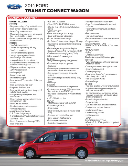
2014 ford transit connect wagon
Standard Equipment
Content includes: Exterior • Bodyside moldings – Gray, molded-in-color
• Front bumper – Gray, molded-in-color
XLT includes all XL content, plus:
Exterior • Bodyside moldings body-color, painted
• Front bumper body-color, painted
• Fog lamps
• Power adjust, heated exterior mirrors with manual fold – Black, molded-in-color
• 4-way adjustable steering column
• 6 -way manual driver seat with manual lumbar and rear map pocket
• 12V powerpoint in rear cargo area
辣果VIN和引擎号查找指南说明书

Your vehicle has several identifying numbers in various places.The Vehicle Identification Number (VIN)is the 17-digit number your Honda dealer uses to register your vehicle for warranty purposes.It is also necessary for licensing and insuring your vehicle.The easiest place to find the VIN is on a plate fastened to the top of the dashboard.You can see it by looking through the windshield on the driver’s side.It is also on the Certification label at-tached to the driver’s doorjamb,and is stamped on the engine com-partment bulkhead.The VIN is also provided in bar code on the Certification label.Identification Numbers282The Engine Number is stamped into the engine block.It is on the front.The Transmission Number is on a label on top of the transmission.Identification Numbers283Specifications (4-cylinder Models)2840.16US gal (0.6)Including the coolant in the reserve tank and that remaining in theengine.Reserve tank capacity:Excluding the oil remaining in the engine.1:2:Specifications (4-cylinder Models)2852:EXSpecifications (6-cylinder Models)2860.16US gal(0.6)Including the coolant in the reserve tank and that remaining in theengine.Reserve tank capacity:Excluding the oil remaining in the engine.1:2:Specifications (6-cylinder Models)2871:2:LX-V6,EX-V6with automatic transmission EX-V6with manual transmission。
东风本田汽车用户手册说明书
目 录车辆简介 ���������������������������������������������2驾驶员与乘员的安全 �����������������������������4介绍有关如何正确使用与保养您车辆的座椅安全带的重要说明,以及关于辅助保护装置的概述和如何利用儿童保护装置保护儿童的重要说明。
仪表与控制装置 ���������������������������������58解释仪表盘上每一盏指示灯和每一个仪表的用途,介绍如何使用仪表板和转向柱上的控制装置。
各项设施 �����������������������������������������106介绍如何操作暖风装置与空调系统/车内空气环境控制系统、音响系统,以及其它便利设施。
驾驶之前 �����������������������������������������133介绍应使用何种汽油,新车如何磨合,以及如何运载行李及其它货物。
驾 驶 ���������������������������������������������145介绍如何起动发动机、变速器换档、驻车等的正确操作方法。
保 养 ���������������������������������������������162“定期保养表”告诉您什么时候应将车辆送到东风本田汽车特约销售服务店进行保养。
另附一张检查项目一览表及如何进行检查的说明。
外观保养 �����������������������������������������209有关清洗和保护车辆外观的建议。
处理意外事故 ����������������������������������216本章节介绍驾车人员有时会遇到的若干问题,以及如何处理这些问题的细节。
技术数据 �����������������������������������������240车辆识别代号、整车尺寸、油液容量以及技术数据。
诺基亚智能手机使用指南说明书
C
Capacities Chart .................... 344, 346 Carbon Monoxide Hazard .............. 52 Carrying Cargo .............................. 202 Cassette Player
Charging System Indicator .... 58, 328 Checklist, Before Driving............. 206 Child Safety ...................................... 20 Child Seats........................................ 25
Before Driving ............................... 191 Belts, Seat ..................................... 8, 41 Beverage Holder............................ 101 Body Repair .................................... 310
Maintenance............................... 279 Usage .................................. 111, 117 Air Outlets (Vents)................ 110, 115 Air Pressure, Tires ........................ 282 Alcohol in Gasoline........................ 350 Aluminum Wheels, Cleaning........ 305 Antifreeze ....................................... 253 Anti-lock Brakes (ABS) Indicator................................ 59, 219 Operation .................................... 218 Anti-theft, Audio System............... 179 Anti-theft Steering Column Lock .. 76
瑞虎 一二三(奇瑞)

13
2)需求介绍话术---NFABI介绍话术(经济性)
N: 通过刚才跟您的交流,看来您对车辆的经济性很在意,是吗?我们奇瑞瑞虎的经济性 主要体现在三个地方,接下来我给您做一下介绍,您看好吗?
F 1: 第一,奇瑞瑞虎使用的1.6 ACTECO高效节能发动机。 B1: 这款发动机使用了进排气门正时控制系统,具有“同转速扭矩最高,同扭矩转速最低”
18
19
3)异议处理话术
顾客:听说SUV的油耗都很高,是不是啊?
解释论证 瑞虎所配备的1.6DVVT高效节能发动机,代表了目前国内外发动机VVT技术 领域的最高水平,是当前众多发动机中的“冠军芯”,这让瑞虎拥有同级别 车型中最低油耗、最高扭矩和最大功率,更重要的是百公里油耗只有7.3L。
I : 瑞虎目前已经拥有超过30万的保有客户。这是目前国内同级车型中保有量最大的车型,
这就是品质的最好说明了。
领先的 经济性
领先的 舒适性
领先的 安全性
16
异议处理话术
尊重 理解 PMP
解释 认证
确认 放心
17
18
3)异议处理话术
顾客:听说SUV的油耗都很高,是不是啊?
尊重、理解、PMP XX先生/小姐,您是说您对SUV车辆的油耗还有一定的担心,是吗? 我理解您的担心。有很多客户在一开始看车的时候,也有这方面的顾虑, 现在的油价天天在涨,如果油耗高的话,以后的使用成本也会非常高。如 果是我买车的话,也会这样考虑的。不过,很多客户在仔细比较了之后, 还是来买了我们的瑞虎。接下来,占用您几分钟的时间,我给您做一个详 细的解释,您看好吗?
CD123-SPECIFIC CHIMERIC ANTIGEN RECEPTOR REDIRECTE
专利名称:CD123-SPECIFIC CHIMERIC ANTIGEN RECEPTOR REDIRECTED T CELLS ANDMETHODS OF THEIR USE发明人:FORMAN, Stephen,MARDIROS, Armen 申请号:US2014/029109申请日:20140314公开号:WO2014/144622A2公开日:20140918专利内容由知识产权出版社提供摘要:A family of chimeric antigen receptors (CARs) containing a CD123 specific scFv was developed to target different epitopes on CD123. In some embodiments, such aCD123 chimeric antigen receptor (CD123CAR) gene includes an anti-CD123 scFv region fused in frame to a modified IgG4 hinge region comprising an S228P substitution, anL235E substitution, and optionally an N297Q substitution; a costimulatory signaling domain; and a T cell receptor (TCR) zeta chain signaling domain. When expressed in healthy donor T cells (CD4/CD8), the CD123CARs redirect T cell specificity and mediated potent effector activity against CD123+ cell lines as well as primary AML patient samples. Further, T cells obtained from patients with active AML can be modified to expressCD123CAR genes and are able to lyse autologous AML blasts . Finally, a single dose of 5.0 x 10 CAR123 T cells results in significantly delayed leukemic progression in mice. These results suggest that CD123CAR-transduced T cells may be used as an immunotherapy for the treatment of high risk AML.申请人:FORMAN, Stephen,MARDIROS, Armen地址:1500 E. Duarte Road Duarte, California 91010 US,1112 N. Columbus AvenueGlendale, California 91202 US 国籍:US,US代理人:DUEPPEN, Lara更多信息请下载全文后查看。
一汽-大众汽车有限公司使用说明书
符号说明该符号表示参阅本手册某章某节的内容,该章节列有重要信息和必须遵守的相关安全注意事项 。
该符号表示本章节未结束,接下页。
该符号表示本章节已结束。
该符号表示必须立即停车。
®该符号表示注册商标,但无此符号的部件并不表示本公司放弃其所有权。
⇒ 该符号表示参阅本章节或给定页码内的警告说明。
列出了可能引发事故或受伤的风险以及规避风险的处理方法,以引起您的警觉。
⇒ ⇒ ⇒ 该符号表示参阅本章节或给定页码内的注意事项,列出了可能损坏汽车的相关信息。
提示凡以该符号开头的文本表示可能损坏汽车的原因,使用本车时务必严格遵守相关警告说明。
凡以该符号开头的文本均与环境保护和燃油经济性有关。
凡以该符号开头的文本均为某章节的补充说明。
鉴于一汽 - 大众汽车有限公司会持续对所有车型进行改进,因此,我们保留随时对车轮、设备或技术规格的某一部分进行修改的权利,敬请理解。
与交付范围、外观、性能、尺寸、重量、油耗、规范以及汽车功能修改的数据资料均为截止印刷时的正确内容(详情请咨询当地一汽 - 大众特许经销商)。
本手册中的所有信息、图示或描述均不可视为法律承诺。
未经一汽 - 大众汽车有限公司的书面同意,不得翻印、复制或翻译本说明书的任何部分。
本公司郑重申明保留著作权法所规定的所有权益及修改的权利。
中国印刷© 2013 年 6 月 一汽-大众汽车有限公司衷心感谢您对本公司及本公司产品的信任!本车技术先进,工艺精良,性能卓越,具有优良的动力性、经济性、舒适性和安全性,并配有众多便利功能供您使用。
首次使用本车前,请务必仔细阅读本使用说明书,尽快熟悉本车结构和各种功能、使用方法及本公司有关规定,正确使用和养护汽车,充分利用本车的优良性能,确保安全行驶,保持汽车的自身价值。
本车所有车型均已通过国家强制性产品认证(CCC认证)。
本说明书旨在为用户提供汽车使用和维护方面的说明指导,您所购汽车的具体配置请核对购车合同。
如您对本车及本套随车文件有任何疑问,敬请垂询本公司特许经销商。
运营测试123自驾游全攻略

运营测试123自驾游全攻略(原创实用版)目录1.自驾游的自由与灵活性2.自驾游的旅行方式及对时间的掌控3.自驾游的注意事项及建议4.测试 123正文自驾游全攻略自驾游是一种非常受欢迎的旅游方式,它为人们提供了极大的自由与灵活性。
这种自由体现在旅行方式和对时间的掌控上。
自驾车可以延展旅行半径,让你可以登高望远或随时下车拍照留念。
你可以很早就停下来,或者睡到日上三竿,不必担心错过了下一班火车。
在大风雨的坏天气中,你可以躲在车里躲避风雨。
你可以倾听鸟儿在山谷中鸣唱,开着窗在富氧环境中深呼吸。
你也可以索性停下来,在路旁的清潭中游泳,或者在林地中铺个垫子午睡。
在一幅美景前,你可以驻足安营,等到第二天早上看日出的霞光。
自驾游的旅行方式及对时间的掌控是其最大的优点。
你可以根据自己的喜好和需求来安排行程,不受时间、地点的限制。
这种灵活性使自驾游成为了许多人的首选。
然而,自驾游也有其注意事项和建议。
首先,驾驶者需要有足够的驾驶经验和技能。
在长途驾驶中,驾驶者需要保持清醒和集中注意力,以确保行车安全。
其次,车辆需要保持良好的运行状态,以避免在旅途中出现故障。
此外,旅行者需要提前规划好路线,了解沿途的天气、交通等情况,以便做好充分的准备。
在这里,我们为大家提供一个简单的自驾游测试:测试 123。
这个测试可以帮助你了解自己是否适合自驾游,以及如何更好地准备和规划自驾游行程。
通过这个测试,你可以了解自己的驾驶技能、行程规划能力、应变能力等方面的水平。
根据测试结果,你可以更好地提高自己的自驾游技能,为未来的自驾游做好充分的准备。
总之,自驾游是一种非常有趣和充满挑战的旅行方式。
如果你喜欢自由和灵活,自驾游是一个不错的选择。
汽车slogan文案全集
目录汽车品牌口号收集 (2)1.千里马 (3)2.别克 (4)3.东南菱帅 (5)4.上海大众 (5)5.奥迪AUDI (7)6.新甲壳虫New Beatle (8)7.高尔夫GOLF (8)8.夏朗SHARAN (9)9.捷达JETTA (9)10.宝莱BORA (9)11.高尔GOL (10)12。
马自达福美来323 (10)13.马自达6 Mazda6 (10)14.福美来 (10)15.宝马BMW (11)16。
梅塞德斯——奔驰Mercedes-Benz (12)17。
沃尔沃VOLVO (13)18.日产汽车NISSAN (13)19.丰田汽车TOYOTA (14)20。
吉普anywhere i can reach__jeep (15)21.绅宝SAAB (15)22.福特 (15)23.雪佛兰CHEVROLET (16)24。
现代汽车HYUNDAI (16)25.威乐VELA (17)26.本田 (18)27。
东风雪铁龙 (19)28.中华轿车Brilliance Auto (20)29。
奇瑞 (20)30。
菲亚特 (21)31.三菱欧蓝德OUTLANDER (21)32。
红旗 (22)33.吉利 (22)34.华普汽车MAPLE AUTOMOBILE (22)35.江淮瑞风REFINE (22)36.Sovereign (23)37。
凯迪拉克 (23)38.荣威 (27)39.MG (28)40.奔腾 (29)41.长安汽车: (29)42.比亚迪 (30)43.东风风神 (30)44.长城汽车 (31)汽车品牌口号收集日系丰田——车到山前必有路,有路就有丰田车丰田新口号——更远、更新。
--TOYOTO以先进技术挑战汽车梦想本田——The Power of Dreams-梦想的力量三菱——Drive@earth:“驰骋地球,关爱地球”日产-shift the future超越未来。
德系梅赛德斯-奔驰——领导时代,驾驭未来宝马——驾乘乐趣,创新极限奥迪——突破科技、启迪未来大众——汽车价值典范大众新口号——处于对企业的爱奔驰戴姆勒——“精益求精,永远领先”和“追求卓越”斯柯达——简单、聪明其他福特——你的世界,从此无界雪铁龙——想在你之前起亚——用心全为你雷诺——让汽车称为一个小家迷你(mini)--她可爱吗?(ISITLOVE?)沃尔沃——For Life 关爱生命,享受生活现代——Drive your way 驾驭你的路标致——Engine to be enjoyed 享受引擎的力量具体车型口号上海别克——当代精神,当代车东风——买我东风车,还你一条龙大众甲壳虫——想想还是小的好桑塔纳——拥有桑塔纳,走遍天下都不怕双龙汽车——世上无难路,只要有双龙南京菲亚特—世界家轿王五十铃汽车—让我们充分掌握能多快好省的运输货物的拖车头吧。
- 1、下载文档前请自行甄别文档内容的完整性,平台不提供额外的编辑、内容补充、找答案等附加服务。
- 2、"仅部分预览"的文档,不可在线预览部分如存在完整性等问题,可反馈申请退款(可完整预览的文档不适用该条件!)。
- 3、如文档侵犯您的权益,请联系客服反馈,我们会尽快为您处理(人工客服工作时间:9:00-18:30)。
汽车的发动机的种类和发动机性能参数解释汽车的心脏——发动机发动机是汽车的心脏,为汽车的行走提供动力,汽车的动力性、经济性、环保性。
简单上讲发动机就是一个能量转换机构,即将汽油(柴油)的热能,通过在密封汽缸内燃烧气体膨胀时,推动活塞作功,转变为机械能,这是发动机最基本原理。
发动机所有结构都是为能量转换服务的,虽然发动机伴随着汽车走过了100多年的历史,无论是在设计上、制造上、工艺上还是在性能上、控制上都有很大的提高,其基本原理仍然未变,这是一个富于创造的时代,那些发动机设计者们,不断地将最新科技与发动机融为一体,把发动机变成一个复杂的机电一体化产品,使发动机性能达到近乎完善的程度,各世界著名汽车厂商也将发动机的性能作为竞争亮点,那么什么是发动机性能呢?发动机的种类现代高科技在发动机上得到完美的体现,一些新技术、新结构广泛应用在发动机上。
如V12、V8、V6发动机:它们均指气缸排列成V型,这种发动机充分利用动力学原理,具有良好的平稳性,增大发动机排量,降低发动机高度。
如:AudiA860使用W12-12缸V型排列发动机,BENZS600使用V12-12缸IV型排列发动机等。
一般情况下,按照排量大小的不同发动机分为三缸、四缸、六缸、八缸几种类型。
目前1.3L-2.3L排量的车大多采用直列四缸发动机,其特点是体积小、结构简单、维修方便;2.5L以上的排量一般采用多缸设计,其中有直列六缸,如宝马;也有呈一定角度分两边排列的V型六缸发动机,可有效果降低震动和噪音,如别克车系;一般来说排量越大,发动机的功率就越高。
但现在也有些小排量的车通过涡轮增压、多气门、可变正时器等技术来提高功率。
发动机的性能发动机性能参数也就是最能体现发动机工作能力的参数,主要包括:排量、最大功率、最大扭矩。
关于排量:排量往往与发动机功率联系在一起,排量的大小影响着发动机功率的高低,通常也把它作为划分高、中、低档车的标准。
什么是排量呢?大家都清楚,活塞在气缸内作往复上下运动,这样往复运动必然有一个最高点和最低点,活塞从最低点到最高点所扫过的气缸容积,称为单缸排量,所有气缸排量总和称为发动机排量,很显然3.0的排量对你来说应该心满意足了。
关于最大功率与最大扭矩:这往往是大家最容易混淆的两个概念,有人认为车的功率越大,力就越大,其实不然。
同样300匹马力,在跑车上可以让车跑到250公里/小时以上的速度,但在一部货柜车上,可能最多只有150公里/小时的速度,但它能拖动30-40吨重的货柜。
这里面的奥秘就在于两部车的扭矩有很大的不同,简单来说,功率表现在高转速,在发动机性能曲线图上,随着转速上升而明显上升,它决定了车子能跑多快,扭矩不一定在高转速时发挥,在曲线图上较为平直,它可以决定车行驶时的力量,包括加速性。
在解读发动机参数时,需要注意的是,不要单看功率有多大,同时也要看到扭力参数,并注意当发动机处于最大功率、最大扭矩时的转速,当然以转速值稍低为好。
汽车的魅力都在它的动感,而动感的灵魂却在发动机,发动机发展到今天,已经非常完善,很难想象失去发动机的日子,汽车会是一个什么样子。
汽车底盘传动、行驶、转向、制动系统详解汽车底盘示意图底盘作用是支承、安装汽车发动机及其各部件、总成,形成汽车的整体造型,并接受发动机的动力,使汽车产生运动,保证正常行驶。
底盘由传动系、行驶系、转向系和制动系四部分组成。
(1)传动系传动系简介传动系一般由离合器、变速器、万向传动装置、主减速器、差速器和半轴等组成。
传动系的功用汽车发动机所发出的动力靠传动系传递到驱动车轮。
传动系具有减速、变速、倒车、中断动力、轮间差速和轴间差速等功能,与发动机配合工作,能保证汽车在各种工况条件下的正常行驶,并具有良好的动力性和经济性。
传动系的种类和组成传动系可按能量传递方式的不同,划分为机械传动、液力传动、液压传动、电传动等。
汽车底盘传动、行驶、转向、制动系统详解2∙易车网∙2009年09月20日 13:30∙来源:易车网∙作者:俞士强∙图片新闻(2)行驶系行驶系由汽车的车架、车桥、车轮(注意)和悬架等组成。
汽车的车架、车桥、车轮和悬架等组成了行驶系,行驶系的功用是:①接受传动系的动力,通过驱动轮与路面的作用产生牵引力,使汽车正常行驶;②承受汽车的总重量和地面的反力;③缓和不平路面对车身造成的冲击,衰减汽车行驶中的振动,保持行驶的平顺性;④与转向系配合,保证汽车操纵稳定性。
(3)转向系简介汽车上用来改变或恢复其行驶方向的专设机构称为汽车转向系统。
转向系统的基本组成①转向操纵机构主要由转向盘、转向轴、转向管柱等组成。
②转向器将转向盘的转动变为转向摇臂的摆动或齿条轴的直线往复运动,并对转向操纵力进行放大的机构。
转向器一般固定在汽车车架或车身上,转向操纵力通过转向器后一般还会改变传动方向。
③转向传动机构将转向器输出的力和运动传给车轮(转向节),并使左右车轮按一定关系进行偏转的机构。
转向系统的类型及工作原理按转向能源的不同,转向系统可分为机械转向系统和动力转向系统两大类。
(4)制动系简介汽车上用以使外界(主要是路面)在汽车某些部分(主要是车轮)施加一定的力,从而对其进行一定程度的强制制动的一系列专门装置统称为制动系统。
其作用是:使行驶中的汽车按照驾驶员的要求进行强制减速甚至停车;使已停驶的汽车在各种道路条件下(包括在坡道上)稳定驻车;使下坡行驶的汽车速度保持稳定。
对汽车起制动作用的只能是作用在汽车上且方向与汽车行驶方向相反的外力,而这些外力的大小都是随机的、不可控制的,因此汽车上必须装设一系列专门装置以实现上述功能。
分类:①按制动系统的作用制动系统可分为行车制动系统、驻车制动系统、应急制动系统及辅助制动系统等。
用以使行驶中的汽车降低速度甚至停车的制动系统称为行车制动系统;用以使已停驶的汽车驻留原地不动的制动系统则称为驻车制动系统;在行车制动系统失效的情况下,保证汽车仍能实现减速或停车的制动系统称为应急制动系统;在行车过程中,辅助行车制动系统降低车速或保持车速稳定,但不能将车辆紧急制停的制动系统称为辅助制动系统。
上述各制动系统中,行车制动系统和驻车制动系统是每一辆汽车都必须具备的。
②按制动操纵能源制动系统可分为人力制动系统、动力制动系统和伺服制动系统等。
以驾驶员的肌体作为唯一制动能源的制动系统称为人力制动系统;完全靠由发动机的动力转化而成的气压或液压形式的势能进行制动的系统称为动力制动系统;兼用人力和发动机动力进行制动的制动系统称为伺服制动系统或助力制动系统。
③按制动能量的传输方式制动系统可分为机械式、液压式、气压式、电磁式等。
同时采用两种以上传能方式的制动系称为组合式制动系统。
动系统一般由制动操纵机构和制动器两个主要部分组成:①制动操纵机构产生制动动作、控制制动效果并将制动能量传输到制动器的各个部件,以及制动轮缸和制动管路。
②制动器产生阻碍车辆的运动或运动趋势的力(制动力)的部件。
汽车上常用的制动器都是利用固定元件与旋转元件工作表面的摩擦而产生制动力矩,称为摩擦制动器。
它有鼓式制动器和盘式制动器两种结构型式。
汽车变速器操纵装置的作用以及不同分类∙易车网∙2009年09月20日 13:35∙来源:易车网∙作者:俞士强∙图片新闻汽车变速器具有这样几个功用:(1)改变传动比,扩大驱动轮转矩和转速的变化范围,以适应经常变化的行驶条件,同时使发动机在有利(功率较高而油耗较低)的工况下工作;(2)在发动机旋转方向不变情况下,是汽车能倒退行驶;(3)利用空挡,中断动力传递,以发动机能够起动、怠速,并便于变速器换档或进行动力输出。
变速器是由变速传动机构和操纵机构组成,需要时,还可以加装动力输出器。
在分类上有两种方式:按传动比变化方式和按操纵方式的不同来分。
按传动比变化方式来分:有级式变速器是目前使用最广的一种。
它采用齿轮传动,具有若干个定值传动比。
按所用轮系型式不同,有轴线固定式变速器(普通变速器)和轴线旋转式变速器(行星齿轮变速器)两种。
目前,轿车和轻、中型货车变速器的传动比通常有3-5个前进档和一个倒档,在重型货车用的组合式变速器中,则有更多档位。
所谓变速器档数即指其前进档位数。
无级式变速器其的传动比在一定的数值范围内可按无限多级变化,常见的有电力式和液力式(动液式)两种。
电力式无级变速器的变速传动部件为直流串激电动机,除在无轨电车上应用外,在超重型自卸车传动系中也有广泛采用的趋势。
动液式无级变速器的传动部件为液力变矩器。
综合式变速器是指由液力变矩器和齿轮式有级变速器组成的液力机械式变速器,其传动比可在最大指与最小值之间的几个间断的范围内作无级变化,目前应用较多。
按操纵方式来分:强制操纵式变速器是靠驾驶员直接操纵变速杆换档。
自动操纵式变速器其传动比选择和换档是自动进行的,所谓“自动”,是指机械变速器每个档位的变换是借助反映发动机负荷和车速的信号系统来控制换档系统的执行元件而实现的。
驾驶员只需操纵加速踏板以控制车速。
半自动操纵式变速器有两种型式:一种是常用的几个档位自动操纵,其余档位则由驾驶员操纵;另一种是预选式,即驾驶员预先用按钮选定档位,在踩下离合器踏板或松开加速踏板时,接通一个电磁装置或液压装置来进行换档(一)汽车轮胎基本常识车轮与轮胎是汽车行驶系中的重要部件,其功用是:支承整车;缓和由路面传来的冲击力;通过轮胎同路面间存在的附着作用来产生—驱动力和制动力厂汽车转弯行驶时产生平衡离心力的侧抗力,在保证汽车正常转向行驶的同时,通过车轮产生的自动回正力矩,使汽车保持直线行驶方向;承担越障提高通过性的作用等。
现代汽车几乎都采用充气轮胎。
轮胎安装在轮辋上,直接与路面接触,它的作用是:1)和汽车悬架共同来.缓和汽车行驶时所受到的冲击,并衰减由此而产生的振动,以保证汽车有良好的乘坐舒适性和行驶平顺性。
2)保证车轮和路面有良好的附着性,以提高汽车的牵引性、制动性和通过性。
3)承受汽车的重力,并传递其它方向的力和力矩。
因此,轮胎必须有适宜的弹性和承受载荷的能力。
同时,在其与路面直接接触的胎面部分,应具有用以增强附着作用的花纹。
此外,车轮滚动时,轮胎在所承受的重力和由于道路不平而产生的冲击载荷作用下受到压缩。
压缩消耗的功,在载荷去除后并不能完全回收,有一部分消耗于橡胶的内摩擦,结果使得轮胎发热。
温度过高将严重地影响橡胶的性能和轮胎的组织,从而大大增加轮胎的磨损而缩短轮胎的使用寿命。
1.轮胎分类汽车轮胎按用途分,可分为载货汽车轮胎和轿车轮胎;而载货汽车轮胎又分为重型、中型和轻型载货汽车轮胎。
汽车轮胎按胎体结构不同可分为充气轮胎和实心轮胎。
现代汽车绝大多数采用充气轮胎。
充气轮胎按组成结构不同,又分为有内胎轮胎和无内胎轮胎两种。
充气轮胎按胎体中帘线排列的方向不同,还可分为普通斜交胎、带束斜交胎和子午线胎。
