ewsdf
自己整理的标准直齿圆柱齿轮的参数计算

双啮检查时的法向压力 角 a啮
外
齿 奇 轮
数 齿 偶 数 齿
量柱中心处的端面压力 角 aM
ha*=1 c*=0.25 正常 齿
内
齿 数 Ems 奇内= -Emi 奇外 轮
齿
奇
ha*=0.8 c*=0.3 短齿
Emi 奇内= -Ems 奇内
标准直齿圆柱齿轮参数计算
1. 齿轮的基本参数有;
齿轮模数是有国家标准的(GB1357-78) 模数标准系列(优先选用)1、1.25、1.5、2、2.5、3、4、5、6、8、10、12、14、16、 20、25、32、40、50 模数标准系列(可以选用)1.75、2.25、2.75、3.5、4.5、5.5、7、9、14、18、22、28、 36、45 模数标准系列(尽可能不用)3.25、3.75、6.5、11、30 上面数值意外为非标准齿轮,不要采用!
分度圆直径 d=mz 齿顶圆直径 da=(z+2)m=m(z+2ha*) 齿根圆直径 df=d-2hf=d- 2(ha*+c*)m=mz-2.5m 齿顶高 ha=ha**m =m 齿根高 hf=(ha*+c*)m=1.25m 全齿高 h=ha+hf=(2ha*+c*)m=2.25m 基圆直径 db=dcosa=mzcosa 齿距 P=(Pi)m 齿 厚 s=P/2= (π)m/2
齿槽宽 e=P/2= (π)m/2 标准中心距 a = (d1+d2)= m(z1+z2)
2 2 1 1
跨齿数 K=az/180o+0.5 或 K=
跨齿数 压力角
1 9
������ +0.5
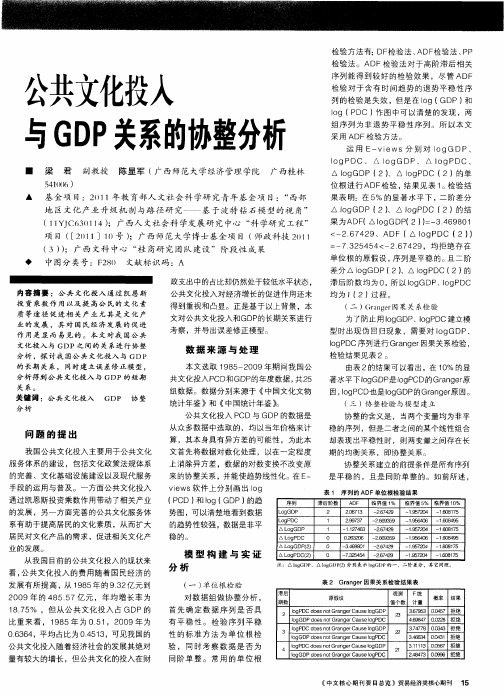
公共文化投入与GDP关系的协整分析
▲ 基 金项 目:2 1 年教 育部人 文社会 科 学研 究青年基金 项 目:“ 0 1 西部
地 区文化 产业 升级 机 制与路 径研 究—— 基 于波 特钻 石模 型的视 角 ”
( Y C 3 1 ;广西人文社会科 学发展研 究 中心 “ 学研 究工程” 1 d 6 0 4) 1 1 科 项 目 ( 2 1 ]1 [ 0 ) 1 0号 ;广西 师范大 学博 士基金项 目 ( 师政科技 2 I 0 I ( ) 3) ;广 西 文科 中心 “ 商研 究 团队 建设 ”阶段 性 成果 桂
期 的均 衡 关 系 ,即 协 整 关 系 。
问 题 的 提 出
我国公共文化投入 主要用于公共文化 服 务体系的建设 ,包括 文化 政策法规体系
的 完 善 、文 化 基 础 设 施 建设 以及 现代 服 务
协 整关系建立的前提 条件是所有序列 是平稳 的 ,且是 同阶单整 的。如前所述 ,
Ig D o P C序列进行 Grn e 因果关系检验 , agr
检 验 结 果 见 表 2。 由 表 2的结 果 可 以看 出 ,在 1 % 的显 0
的 长期 关 系 , 同 时 建 立误 差修 正模 型 ,
分析得到公共文化投入与 G DP的短 期
关 系。
著水平 Tlg o GDP I P 是 o CD的Grn e 原 g gr a
◆ 中图分类号 :F 8 文献标识码 :A 20
政 支 出 中 的 占比 却仍 然 处 于较 低 水 平 状态 ,
内 容 摘 要 : 公 共 文 化 投 入 通 过 凯恩 斯
73 5 5 <一 7 2 .2 4 4 2 6 4 9,均 拒绝 存在
单位根 的原假设 , 序列 是平稳 的。 二阶 且
海尔产品延保说明

海尔延保服务说明A、什么是海尔延保服务?家电延期保修服务简称“延保服务”,即海尔为购买家电产品的消费者提供的,在厂家法定保修期满后,对产品维修费用所作的补偿服务,英文缩写“EWS”。
例如:消费者在购买或者安装维修电器时,销售人员会告诉消费者有一个延期保修服务计划合同的选择,以便在国家、厂方明确的“三包”规定之余,再享受1-5年不等的免费保修服务。
消费者购买延期保修合同以后,不管是一年、两年、三年、四年、五年,在延期保修合同时间内,只要机器有正常的损坏,消费者可以给海尔打电话。
客服中心就会派签约的服务商上门去修理或者是免费更换新机器,消费者不用花一分钱,而且不管你修多少次。
比如说今天你做了这个服务,明天别的部件又坏了一样可以修,延保期内维修不限次,但累计维修费用不能超过机器的价格,如维修费用超出机器价格的,由销售商为用户免费更换同等价值机器,且延期保修服务合同解除。
目前,海尔保服务只提供在厂商保修期限内的家电产品的延期保修服务的销售,且限于热水器(不含太阳能)、洗衣机、平板电视、冰箱冷柜、厨电(不含吸油烟机)(不含所有产品商用型号)B、海尔延保的特色:更省心:(全国均可)一个电话解决问题.24小时*7天*365天全天候服务更安心:完备的售后服务.使用厂商授权维修中心专业维修更省钱:延保期间,维修成本为零更保值:可转让(和机器一起)更超值:免费保养,最大限度保证机器不坏。
C、海尔延保服务与其他商场延保的区别及优势:海尔延保服务和商场延保区别:1、商场延保与海尔无任何关系,延保期内的服务由其自行负责。
2、商场延保不享受海尔的延保增值服务海尔延保的优势:1、海尔延保提供每年一次的免费保养,最大限度保证机器不坏。
2、海尔拥有自己的售后网络,有自己的服务队伍,服务质量有保证;3、海尔延保服务提供原厂保修,原厂零配件D、海尔推出延保服务的初衷:海尔推出的延保服务也是出于对用户的考虑:1、保证用户家电正常使用,延长家电使用寿命:家电换季时,需对机器进行保养和清洁,起到延长家电的使用寿命、减少家电故障、节省能耗的效果,用户自己做不专业,反而容易将机器弄坏;找专业公司做,需要收费,增加家电使用成本。
抗SSDF攻击的EWSPRT协作频谱感知方案

nwC S s e enm da na cd w i t euni r ait r i t t E P T .I epooe e S c m a e se hne e he sq et lpo bly a o e ( WS R ) n t r sd h g d a b i t s h p shm , ahscn a srS )f t a e ato il a dc i i ee ydt t n t nclc e c e e ec odr ue( U i l m ks —bto l eio v nr e ci , h l tt e y s r y w c sn a g e o e oe s h
A s a tT i p prcm a stesni e o a c f ee l yi lco e t eset m sni ( S ) bt c:hs ae o pr h e s gpr r neo svr pc opr i pc u es g C S r e n fm at a av r n s a g s n e pc u e s gdt flf ai ( S F t c ont er i nt rs n rs t a t t i drset m sni a s ctn S D )a ak i cg iv a o e k ,adpee s re e u r n aai o i t n i d wo n
案相 比 ,WS R E P T方案 能够 更有 效地抵 抗 SD S F攻 击 。 关键 词 : 知 无 线 电 ; 认 协作 频谱 感 知 ; 改 感知数 据 攻 击 ; 篡 加权 序 贯检 测 中 图分类 号 : 9 2 文献 标识 码 : A di1 .99 ji n 10 —83 .0 10 .1 o:0 36 / . s .0 1 9 x2 1 .3 0 5 s
直流输电术语及缩略词
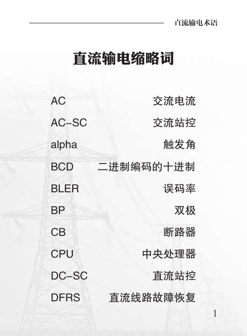
直流输电缩略词AC交流电流AC-SC交流站控alpha触发角BCD二进制编码的十进制BLER误码率BP双极CB断路器CPU中央处理器DC-SC直流站控DFRS直流线路故障恢复DVC直流电压控制ES接地刀ESOF紧急停运FASOF快速停运FR移相闭锁gamma熄弧角OLT空载加压试验HMI人机界面HVDC高压直流输电HSNBS高速中性母线开关HVDC高压直流输电系统HW硬件I&M启动和监视系统IdE直流中性线电流IdH500KV直流换流器电流Idref计算的直流电流指令IdrefAC稳定控制直流电流指令IdrefDC运行人员下发直流电流计算指令IdrefMAN运行人员手动设定的电流指令Imarg裕度电流Imax最大直流电流限制Imin最小直流电流限制Imode电流控制模式INV逆变侧Iref直流电流整定值I/O输入/输出LAN局域网WAN广域网LED发光二极管OLT空载升压OWS操作员工作站PCL极电流限制功能PCOC极电流指令配合PmodBP双极功率控制模式POAC稳定控制功率指令计算PODC设定功率功率指令计算PPT极间功率转移Pref功率整定值PSD功率摇摆阻尼PSS功率摇摆稳定RCD100切换逻辑模块Rdc直流线路阻抗Rearth电极线和接地极阻抗RECT整流侧RVC整流侧电压计算SER顺序事件记录SW软件TCC分接头控制TFR暂态故障录波TNA暂态网络分析仪Uref直流电压整定值Ud直流电压Ud1极1直流电压Ud2极2直流电压Ud RECT CALC计算的整流侧电压Ud RECT MEAS测量的整流侧电压UdEarth电极线接地极直流电压降Udio换流变阀侧理想空载直流电压UdL500kV直流线路电压UdN直流中性线电压Uprim换流变压器原边电压Usec换流变压器副边电压VBE阀基电子设备VDCL低压限流功能MCB微型断路器MRS金属回路开关MRTB金属回路转换开关SER顺序事件记录TFR暂态故障录波SERVER服务器OWS操作员工作站DWS站长工作站EWS工程师工作站TWS培训工作站α触发延迟角β超前触发角γ关断角μ换相角CEC电流误差特性CMC电流裕度补偿COCA稳定控制电流指令计算COCB双极功率模式电流指令计算CSD可控停运CT电流互感器DS隔离刀闸DC直流电流直流输电术语高压直流输电系统high voltage direct cur-rent transmission system,HVDC transmission sys-tem以高压直流的形式输送电能的系统。
齿轮齿条传动设计计算

程序设计: 邓 时俊 2002.06
10026 ② 30202
1.5
22
0
齿条节线至基准面距离
齿条长度
L2
第Ⅰ公差组精度等级
第Ⅱ公差组精度等级
第Ⅲ公差组精度等级
输入方式 1:
23.5 毫米 1000 毫米
8 7 7
齿轮齿厚上偏差代码
齿轮齿厚下偏差代码
齿条齿厚上偏差代码
齿条齿厚下偏差代码
最法向侧隙
说明:齿条节线 是与齿轮分度圆 相切的线
注:齿厚极限偏 差共14 种,越往 后间隙越大: C=+fpt,D=0, E=-2fpt,F=4fpt,
G,H,J, K,L,M,N, P,R=-40fpt, S=-50fpt (单 位:微米)
注:如果侧隙不 合适,可重新选 择齿厚极限偏差 种类。
dp20 dp2
齿 面 接 触 斑 点 按高度
按长度
X方向轴线平行度公差 f x
Y方向轴线平行度公差 f y 安装距极限偏差 ±fa 齿坯公差:
孔径尺寸公差
顶圆孔尺径寸形公状差公(差用作基
准)
(不用
作基准)
图样标注: 齿轮1
8
0.05 毫米 0.014 毫米 0.013 毫米 0.011 毫米
GB
IT7
1G8B00
IT6
1G8B00
IT11I,T8但不大 1800 于 0.15
-7
-7
齿轮2
8
-7
-7
打印终止 ***********************
0.011 毫米 45% 60% 0.011 毫米 0.0055 毫米 0.0195 毫米
毫米
-0.1 -0.2 -0.15 注:-0齿.2厚5 上 、下偏差两
电力英语缩写搜集

负荷指令计算机 联锁保护 标么值 电力系统稳定器 电压互感器 工作票 额定 上升 辅机故障减负荷 电抗器 有准备的 通道切换准备就绪 准备启动 参考值 调整器 远方的 重新启动 再热器 转/秒
RO rpm(r.p.m.)revolution per minute RT RTD RTS surge arrester SA static condenser SC schedule scoop sequence centrol system SCS static frequency converter system SFC SH shunt capacitor SIS SMA SOE softstart spin stop SSD steam turbine ST start 来自DGTD-00-0401燃机励磁系统调试程序 STD step SV SVS SWGR TBV TCA turbine control system TCS TDE test TF trip ThrClnTrans(three-column transformer) TN-C-S TOC transducer
pack
RO p.u. PSS PT PTW
porential transformer rated raise
RB reactor ready READY FOR CHANNEL TRANSFER ready to start reference value regulator remote reset RH rms
频率表 炉膛安全系统 炉膛安全监控系统 发电机辅助屏 发电机(电路)断路器 发电机控制面板 发电机 主接地开关 发电机保护继电屏 叶片通道温度 燃气轮机 高密度聚乙烯 高压 高压主气门 安全阀整定? 增加 增加读数 资料 逆变器 进口可转导叶 输入/输出 中压 输入放大器卡件 顶轴油泵 慢转 液化天然气 就地 就地控制间 下降 低压 主要故障 手动的 主变 手动电压调节
船舶英文缩写

苏教版小学英语五年级[上册]知识点汇总
![苏教版小学英语五年级[上册]知识点汇总](https://img.taocdn.com/s3/m/f2ceebd2d1f34693daef3e9d.png)
WORD 格式整理苏教版小学英语五年级上册知识点U n i t 1 G o l d i l o c k s a n d t h e t h r ee b ea r s一、单词(默写)1. b e a r 熊2. f o r est 森林3. t h e r e(与 b e 连用)有4. h o u se 房子5.so u p 汤6. j u st r i g h t 正合适7. r o o m 房间8. h ar d 硬的9. so f t 柔软的 1 0. a f r a i d 害怕的 1 1. t h e i r 他们的 1 2. h e r 她(宾格) 1 3. h e l p 救命 1 4. b e si d e 在⋯⋯旁边 1 5. b e t w e e n 在⋯⋯中间 1 6. r e a l l y 真正地 1 7. t h e n 然后 1 8. f i n d 找到,发现 1 9. i n f r o n t o f 在⋯⋯前面二、词组(默写)1 、i n t h e f o r e st 在森林里2 、a b ea u t i f u l h o u se 一座漂亮的房子3 、h u n g r y a n d t h i r st y 又饿又渴4 、 so m e so u p 一些汤5 、 t o o c o l d / h o t 太冷 / 热6 、 i n t h e r o o m 在房间里7 、 t o o h a r d / so f t 太硬 / 软8 、t h r e e b e ar s 三只熊9 、h a v e so m e ca k e s 吃些蛋糕10 、 i n t h e ki t c h e n 在厨 1 1 、 i n t h e f r i d g e 在冰箱里 1 2 、 f i n d t h ei r c o u si n 发现他们的表弟三、句型(默写)1. T h e r e i s a h o u se i n t h e f o r est. 在森林里有一个房子。
ews-tools 驱动和静态工具 使用说明书
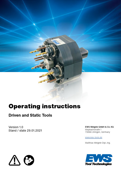
Operating instructionsVersion 1.0Stand / state 29.01.2021Driven and Static ToolsEWS Weigele GmbH & Co. KG Maybachstraße 173066 Uhingen, Germany www.ews-tools.deMatthias Weigele Dipl.-Ing.iGeneral notes:In order to maintain the high quality of your EWS tools for as long as possible, there are someimportant points to consider.Please ensure that the approved speeds, torques and coolant pressures are not exceeded. If you do not have the data sheet, you can download it from our online catalogue, where you will also find other tools suitable for your machine. Of course, you are also welcome to contact our sales and service staff.Dear Customer,By purchasing tools from EWS you have made a good choice and we want to thank you for your trust.Our tooling systems are designed according to the machine specifications and manufactured with high precision using state-of-the-art production units.Operating instructionsPlease carefully read and follow the operating instructions. Keep the operating instructions for the entire service life of the product. Use these operating instructions to familiarise yourself with the device, its correct use and the safety instructions.Intended useEWS driven and static tools are intended for use in turning and milling centres in an industrial environment. Components can be machined by inserting cutting tools.They may only be operated within their specified performance limits.Observance of the assembly instructions and compliance with the maintenance and repair instructions are prerequisites for the intended use.The following materials can be processed in accordance with the intended use: ■Steels■Cast iron materials ■Heavy and light metals ■PlasticsThe user is liable in the event of improper use.1. Safety2. Functions and general description2.1 Example overview of a driven tool2.2 Example overview of a static tool2.3 Labelling of tool holders3. Commissioning and operation3.1 Mounting in the machine3.2 T ool alignment3.3 EWS tool holder according to DIN ISO 10889-63.3 Operation3.3.1 Limit values during operation of driven tools3.3.2. Duty cycle3.3.3 Permissible torque3.3.4 Cooling (KSS) External / Internal3.3.5. Air purge system4. EWS Varia / EWS Varia VX5. Collet chuck holders6. Characteristic values6.1 DIN ISO 10889 (DIN 69880)6.2 Tightening torque screws and BMT6.3 EWS.CAPTO TM6.4 Kennametal KM TM7. Maintenance and care8. Storage, transport and disposal9. T roubleshooting10. Service / Warranty11. T echnical specifications12. Separate operating instructionsAGW = driven toolBMT = bolt mount turret (tool is attached to the turret with screws) IC = internal coolingEC = external coolingKSS = Cooling lubricant4-5 6-7677 8-128 9-10111212121213131314 14-1514151515 15-161617 17-181818CONTENTSLIST OF ABBREVIATIONSWARNINGFor tools with EWS.CyberCon4, the operating manual (LINK) must be observed!DANGERClamp the tools in the holder with the minimum length possible.If the clamping length is too long, dangerous vibrations may occur which can cause seriousinjuries due to parts being flung away, as well as damage to the machining tool/tool holder/turret system.hot surfaces (product can heat up)T ools can heat up to 90°C during operation. pinching and crushing of body parts, e.g. fingers Wear suitable personal protective equipment (PPE). infection through contact with contaminated media risk of poisoning from lubricants and media Wear suitable personal protective equipment (PPE). misuseRead the operating instructions before use and keep them available at all times.Exclude any other type of use or misuse. Always comply with the relevant specifications. If the permissible operating parameters are exceeded, serious injuries to people and damage to the technical equipment may occur. noise emissions depending on the installation situationThe noise emissions from the complete machine must be measured and, if necessary, noise-insulating measures must be taken.DANGEROnly use balanced machining tools.Since driven tools generate large centrifugal forces at high speeds depending on the tool diameter, the machining tools must be balanced. It should be noted that, for safety reasons, their maximum permissible speed must be higher than the maximum permissible speed of the tool holder.DANGERDuring tool changes.Protective gloves must be worn when changing tools.All assembly aids (such as collet spanners) must be removed before using the tool holder.NOTEStructural changes to tools may not be made without the written consent of EWS Weigele GmbH & Co. KG.NOTEFor special features, instructions and notes for your EWS product, please refer to the corresponding separate instructions on the internet at:www.ews-tools.de/en/downloads2. FUNCTIONS AND GENERAL DESCRIPTION2.1E XAMPLE OVERVIEW OF A DRIVEN TOOLHolderHolderSpindle / receptacleLeakage hole for IC (if present)Leakage hole for IC(if present)Spindle / receptacleCoolant nozzleCoolant nozzleShaft with toothingShaft with toothingDrive / tool couplingDrive / tool couplingIndexing hole: Coolant transfer from turretIndexing hole: Coolant transfer from turretSealing ring (O-ring)Sealing ring (O-ring)AlignmentHolderAlignmentClamping sleeveCoolant nozzle Holder Shaft with toothingIndexing hole: coolant transfer fromturret and alignment if necessary (if not additionally available)Sealing ring (O-ring)Strong coolant leakage from the leakage hole, very intense heating of and unusual noises from the tool indicate a defect.The tool must not be operated any further in these cases.In the event of a defect of any kind, always contact our service team (see 9. T roubleshooting ).Each tool supplied by EWS is marked with an article number (e.g. 40.4032CTX) and a serial number (S/N). Depending on the tool type, additional information may be available.Additional information2.2 E XAMPLE OVERVIEW OF A STATIC TOOL2.3 LABELLING OF TOOLSThird-party article numberReversal of direction of rotation (if input and output are in opposite directions)Note on grease lubricationNo dry running (only with IC tools)Pmax... Max. coolant pressure for IC tools, see also P-v diagram MA=... Max. tightening torque on the tool spindle (not driven tool on the turret!)X=... Distance between contact surface and spindle axis Y=... Centre offset to tool shank in Y-direction Z=... Centre offset to tool shank in Z-direction i=... T ransmission ratio Article numberSerial numberDistance3. COMMISSIONING AND OPERATION3.1MOUNTING IN THE MACHINECheck the tool holders for completeness and possible transport damage. Any damage must be reported to EWS Weigele GmbH & Co. KG immediately.■C heck tool holders for damage before each use – if damaged, do not use them. ■C heck that the drive of the turret and the coupling of the tool holder fit together. ■M ake sure the coolant is transferred correctly from the turret to the tool holder.■ The presence, perfect condition and the fit of any add-ons and small parts, e.g. coolant pipes and O-rings, must be checked.■T he contact surfaces of the tool holder and the machine must be clean. ■ Align the VDI tool holder so that the teeth on the shaft engage with the teeth on the clamping bolt on the turret and clamp it securely (see 3.2).■ The max. tightening torque for the VDI clamping bolt can be found in the data sheet provided by the relevant machine manufacturer. For general values see 6.1■ For fastening screws (e.g. Pro-Line, BMT) that are tightened and loosened by the operator, always use a torque spanner. For general values see 6.2■A ll screws (clamping screws) must be tightened firmly as specified. ■N ever operate a driven tool without a tool insert that has been inserted and clamped as instructed! ■W hen not in use, store the tool holder in a safe place to protect it, e.g. in an EWS tool shuttle. ■ To protect the turret against soiling, a tool holder or a sealing plug must always be mounted on the turret.■N ever use compressed air for cleaning, only cleaning cloths.■The tool weights are indicated on the drawing.DANGERRisk of injury from rotating parts!Always keep the machine door closed:3.2 TOOL ALIGNMENTAngled as well as off-axis driven and static tools must be aligned horizontally. This can be ensured by the machine or must be done manually by the operator. Our driven tools are equipped with a ground alignment surface on the tool head for measuring the angular position. For static tools, the outer surface serves as a reference.Alignment of a VDI driven tool with support pin1. Insert the tool into the turret, push it flush against the planar surface.2. Tighten the clamping bolt for the VDI toothing with the recommended torque.[see 6. Characteristic values]3. Slightly loosen the clamping bolt again until the tool can be rotated.4. Check the angular position on the alignment surface.5. Place set screws on the support pin to adjust the angular position.6. Clamp the set screws on the support pin lightly against each other and fix them with clamping screws.7. Check the angular position on the alignment surface again, correct if necessary.8. Re-tighten the clamping bolts for the VDI toothing to the recommended torque.For tools with other alignment systems, such as an alignment bar on the face of the turret, proceed accordingly.Fixing screw (4x)Alignment surfaceAlignment of a BMT driven tool with alignment barUsually, BMT tools are provided with sliding blocks which are guided in grooves on the turret. The sliding blocks are aligned at the factory by EWS for guidance in the turret. Alignment by the operator is therefore usually unnecessary.1. Insert the tool into the turret, push it flush against the planar surface.2. Lightly tighten the fastening screws (4x) crosswise.3. Slightly loosen the screws again until the tool can be turned.4. Check the angular position on the alignment surface.5. Place the adjusting screws on the alignment bar to adjust the angular position.6. Fix the bar with the clamping screw.7. Check the angular position on the alignment surface again, correct if necessary.8. Tighten the fastening screws to the recommended torque [see 6. Characteristic values ].For tools with other alignment systems, such as an alignment bar on the face of the turret, proceed accordingly.3.3 EWS TOOL HOLDER ACCORDING TO DIN ISO 10889When using tool holders with a continuous stop screw in the shaft, the appropriate sealing plug mustalways be fitted to seal against coolant leakage! The O-ring of the sealing plug must be inserted correctly and be in perfect condition.VDI 25 → MA = 25 Nm VDI 30 → MA = 30 Nm VDI 40 → MA = 40 Nm VDI 50 → MA = 50 NmVDI 25 → BG-VS -M14X1.5-S25xx VDI 30 → BG-VS -M18X1.5-S30xx VDI 40 → BG-VS -M22X1.5-S40xxVDI 50 → BG-VS -M28X1.5-S50xxAttention: If coolant gets inside the tool turret, an internal drive can be severely damaged!The following tightening torques (MA) for the sealing plugs must be observed!Seal plug with O-ringStop screwT ool holderPart numbers sealing plugs with O-ring Tightening torques sealing plugAssembled state3.3 OPERATION3.3.1L IMIT VALUES DURING OPERATION OF DRIVEN TOOLS 3.3.2 DUTY CYCLE3.3.3 PERMISSIBLE TORQUETo avoid damage, do not exceed the approved specifications of the tool holder.Standard values based on DIN 3990 / ISO 6336The max. torque values (M1/M2) given in the data sheet apply to uniform loads with light impacts. The permissible torque is significantly reduced in theevent of heavy impact loads. The cutting values of the machining tool must always be selected in such a way that overloading of the driven tool is ruled out.Theoretically permissible duty cycle(ED) for externally and internally cooleddriven tools.For dry-running of internally cooled driven tools, max. 25% duty cycle applies.The permissible duty cycle serves as a guide under normal operating conditions with light chipping and may deviate depending on the type and duration of the load on the driven tool.Reading example:Max. permissible speed of the AGW of 6,000/min:At a speed of 100% (6,000/min), the AGW may run 25% of 10min (2.5min) and 75% of 10min it must stop (7.5min).At a speed of 60% (3,600/min), the AGW may run 50% of 10min (5min) and 50% of 10min it must stop (5min).At a speed of 35% (2,100/min) the AGW may run without limited time (100% ED = infinite).3.3.4 COOLING (KSS) EXTERNAL / INTERNALExternal coolingAfter being transferred from the turret, the coolant is fed to the cutting edge of the machining tool from the outside via ball nozzles or a coolant pipe.Internal coolingAfter being transferred from the turret, the coolant is guided inside the tool holder before being transferred to the clamped machining tool.Before using a driven tool with internal cooling, please always check the max. permissible pressure of the tool. You will find this on the corresponding data sheet. The cooling emulsion must be filtered to 50µ. Driven tools with internal cooling must be maintained at regular intervals. A visual inspection of the turret for water ingress is strongly recommended. Water in the turret disc can cause considerable damage! The EWS service department will be happy to advise you.Internally cooled tools with dry-running capability are identified by the marking on the tool housing (see 2.3 Additional information).However, exclusive dry running is only intended for EC tools.In the event of a defective seal, we strongly recommend that you only use authorised EWS service centres. Coolants other than cooling emulsion (water-oil emulsion) such as oil may cause the tool to heat up more. Their use must be checked on a case-by-case basis. The stated values are only valid for cooling emulsion (water-oil emulsion).3.3.5 AIR PURGE SYSTEMSome tool holders are equipped with a purge air seal.A pressure of 0.4bar to 0.8bar must be maintained and the compressed air must be purified with a filtration of 5μm. The tool holder must not be operated without purge air.4. EWS VARIA / EWS VARIA VXPlease note that the tightening screw may only be tightened to the specified torque of 10 Nm (Varia VX6 Nm). Failure to do so may result in damage to the Varia insert. We recommend the use of a torque spanner. For tool mounting in the inserts we recommend the corresponding mounting device MB-V(X)3, MB-V(X)4 and MB-V5. For tool holders that are equipped with a clamping nut or an axial tightening screw, this device must be used without fail, as otherwise irreparable damage to the inserts may occur. Never tighten clamping nuts or similar in the tool holder (static or driven)! Please check the Varia screws V3 and V4 regularly for wear and replace them if necessary.Insert the collet chuck into the clamping nut before tightening it in the tool holder. When tightening or loosening the clamping nut, it is essential to hold the tool spindle in place. Failure to do so may cause damage to the gearbox or the drive coupling. Countering the rotation by holding the drive coupling is not permitted and will cause damage.Tightening torque for the clamping bolt for tools in accordance with DIN ISO 10889 (DIN 69880):The max. tightening torque for the VDI clamping bolt can be found in the data sheet provided by the relevant machine manufacturer.5.COLLET CHUCK HOLDERSThe max. tightening torque of the collet nut is shown in the following table.6. CHARACTERISTIC VALUES6.1DIN ISO 10889 (DIN 69880)Reference values (EWS and Sauter turrets)6.2 TIGHTENING TORQUE SCREWS AND BMT6.3 EWS CAPTO TM6.4 KENNAMETAL KM TMThe max. tightening torque for the fastening screws can be found in the data sheet provided by the machine manufacturer.The max. tightening torque for the fastening screws can be found in the data sheet provided by the machine manufacturer.7.MAINTENANCE AND CAREFor further information on the use of Kennametal KMTM , please refer to the separate operating instructions.Maintenance: The driven tool and static tool holders are maintenance-free for the user.H owever, we recommend that you have a revision check of the driven tool carried out after 6 months. For this purpose, please send the tool to EWS or an EWS service point in order to define a maintenance cycle, if necessary.Care/cleaning:C lean only with a cleaning cloth. Never use compressed air or cleaning agents. Spray the tools with spray oil after use to prevent corrosion.Service case: W ear parts must be replaced in good time.I n case of defects of any kind, contact the EWS service staff. E-mail:********************Some components and operating materials used in our powered tools are subject to the usual ageing processes, even when the tool is not in operation. The high-performance greases we use have a shelf life of at least 24 months in closed containers according to the manufacturer's instructions. During transport and storage, rolling bearings should be protected against vibrations and shocks as much as possible in order to avoid tribological processes. Special climatic conditions must also be observed to prevent premature tool failure. Excessive temperature fluctuations during transport and storage could cause condensation to form and lead to corrosion inside the tool.Proper storage is guaranteed under the following conditions:The storage location should also always be clean and dry and, in every case, frost-free and ideally cool. Constant vibrations or strong shocks must be avoided.8.STORAGE, TRANSPORT AND DISPOSALWARNING!The cover of an EWS.CyberCon4 must not be dismantled under any circumstances.Failure to observe this will expose you to the risk of electric shock or fire.TIP:Annual maintenance prevents major damage.DANGER!Return transport of an EWS.CyberCon4 tool by air freight is prohibited.Do not dispose of these products with normal household waste.Please contact our service department or return the unit to us.EWS Weigele GmbH & Co. KG T el +49(0)7161-93040-700Fax +49(0)7161-93040-30E-mail ********************EWS Weigele GmbH & Co. KG T el +49(0)7161-93040-700Fax +49(0)7161-93040-30E-mail ********************10. SERVICE / WARRANTYWARNING!Stop the tool immediately if any malfunctions occur. Further work can lead to serious damage to the tool holder as well as to the machine tool. If you are unable to remedy the fault yourself, please contact the EWS service department.Please check visually whether you can eliminate the fault yourself.If this is not possible, please inform us of the following when returning the tool holder for speedy repair processing at the factory: ■Type / Article number■Serial number (S/N) inscription on the tool holder ■Year of manufacture■Type of faultThe EWS service department can be reached at:Services■Professional, fast repair by our service team■Competent advice from our service department in the event of faultsNOTEIn the event of a warranty claim, please contact our service department.The EWS service department can be reached at:11. TECHNICAL SPECIFICATIONS12. SEPARATE OPERATING INSTRUCTIONSSeparate operating instructions are available for other EWS products at https://www.ews-tools.de/en/downloads■T he shipping date at EWS is decisive. ■T he warranty does not cover wear parts such as seals, etc. and any consequential damage caused by them.■T he service life of EWS products depends largely on the corresponding runtime and application.■T he warranty covers all significant defects that can be proven to be the result of material or production faults.The warranty shall expire in the event of: ■ c onversions / alterations / repairs not carried out by EWS or not approved in writing ■ i mproper and inappropriate setup, maintenance and operation ■ i mproper clamping of the machining tool ■ d amage due to unsuitable or defective machining tools ■ c ollisions in the machine tool ■ n on-compliance with the permissible machining data (e.g. speed) with driven tools ■f orce majeure ■ d amage due to non-observance of the operating instructionsEC/EU Declaration of Incorporation for partly completed machinery (original) within the meaning of Directive 2006/42/EC Annex II BScan and access all manuals online!Tooling Systems and Turrets。
各种减速机型号

各种减速机型号行星摆线针轮减速机摆线针轮行星传动基本术语GB 10107.1-88摆线针轮行星传动图示方法GB 10107.2-88摆线针轮行星传动几何要素代号GB 10107.3-88摆线针轮减速机温升测定方法JB/T 5288.1-1991摆线针轮减速机清洁度测定方法JB/T 5288.2-1991摆线针轮减速机承载能力及传动效率测定方法JB/T 5288.3-1991 摆线针轮减速器技术条件SJ 2459-84摆线针轮减速机噪声测定方法JB/T 7253-94摆线针轮减速机产品质量分等JB/T 53324-1997X系列行星摆线针轮减速机8000系列行星摆线针轮减速机TB9000系列摆线针轮减速机B系列上海变速机械厂标准行星摆线针轮减速机B系列化工部标准行星摆线针轮减速机B系列一机部标准行星摆线针轮减速机B系列摆线针轮减速机(泰星标准)F8000系列行星摆线针轮减速机Z系列摆线针轮减速机JB/T 2982-1994SB系列双摆线针轮减速机(JB/T5561-1991)WB 系列微型摆线针轮减速机(永嘉标准)WB 系列微型摆线针轮减速机(双联标准)JXJ系列行星摆线针轮减速机Q系列轻型行星摆线针轮减速机ZB型变幅摆线齿轮减速机BJ 系列摆线针轮减速机BJS系列摆线针轮减速机800 系列摆线针轮减速机600系列摆线针轮减速机SW 系列摆线针轮减速机蜗轮蜗杆减速机圆柱蜗杆传动基本参数GB/T 10085-1988圆柱蜗杆、蜗轮术语及代号GB/T 10086-1988圆柱蜗杆基本齿廓GB/T 10087-1988圆柱蜗杆模数和直径GB/T 10088-1988圆柱蜗杆、蜗轮精度GB/T 10089-1988小模数圆柱蜗杆基本齿廓GB/T 10226-1988小模数圆柱蜗杆、蜗轮精度GB/T 10227-1988圆柱蜗杆、蜗轮图样上应注明的尺寸数据GB/T 12760-1991直廓环面蜗杆、蜗轮精度GB/T 16848-1997WH系列圆弧齿圆柱蜗杆减速机CW系列圆弧圆柱蜗杆减速机GB9147—88CW系列圆弧圆柱蜗杆减速器JB/T 7935-1999KW型锥面包络圆柱蜗杆减速器JB/T 5559-1991ZC1型双级蜗杆及齿轮-蜗杆减速器JB/T 7008-1993PW系列平面二次包络环面蜗杆减速GB/T 16444-1996LCW型立式圆弧圆柱蜗杆减速器JB/T 7848-1995LKW型立式锥面包络圆柱蜗杆减速器JB/T 7847-1995HW系列直廓环面蜗杆减速器JB/T 7936-1999SCW系列轴装式圆弧圆柱蜗杆减速器JB/T 6387-1992TP系列平面包络环面蜗杆减速器JB/T 9051-1999轮胎定型硫化机用平面二次包络环面蜗杆减速机HG/T 2738-95 WD、WS系列圆柱蜗杆减速机WP、WD系列蜗轮蜗杆减速机M系列多面安装圆弧圆柱蜗杆减速机WC系列圆柱蜗杆减速机WXJ系列圆柱蜗杆减速机WSJ系列圆柱蜗杆减速机WCJ型圆柱蜗杆减速机W型圆弧齿圆柱蜗杆减速机A型立式圆柱蜗杆减速机M型立式圆柱蜗杆减速机MA系列立式蜗轮蜗杆减速机NMRV型蜗杆减速机(Q/JF 01-1999)NMRV型蜗杆减速机(嘉诚标准)ANRV系列蜗轮蜗杆减速电动机BRV系列变速型蜗杆减速器WR型蜗杆减速机WQ型圆柱蜗杆减速机WS 万用型蜗轮蜗杆减速机WL型万用型蜗轮减速机WDH 型蜗轮蜗杆减速机WX 型蜗杆减速机WVF蜗杆减速机WWJ系列蜗杆减速器WJL系列蜗杆减速机WJ系列中空轴型蜗杆减速机JRST系列多置式蜗杆减速机GCWS系列圆弧齿圆柱蜗杆减速机CWS型圆弧圆柱蜗杆减速机QT型蜗轮减速机LM型圆柱蜗轮减速机DKWU-F锥面络圆柱蜗杆减速器SKWU型轴装式锥面包络蜗杆减速器RD型二次包络蜗轮减速器VF系列蜗轮蜗杆减速机QW型平面二次包络环面蜗杆减速机XLS系列丝械螺母式阀门减速器XLHJ系列离合式阀门减速器XJ系列阀门减速器XGJ系列含轴承单级阀门减速器XDJ系列地下用二级传动阀门减速器XB系列多回转阀门减速器TSRV系列不锈钢蜗轮减速器QDX3-CF系列部分回转型阀门手动装置ZQDX3系列部分回转型阀门手动装置SQDX3系列部分回转型阀门手动装置XQDX3系列部分回转型阀门手动装置QDX3-C系列部分回转型阀门电动装置QDX3-D系列部分回转型阀门电动装置QDX3-G系列部分回转型阀门手动装置QDX3-S系列部分回转型阀门手动装置QDX3系列部分回转型阀门手动装置FQDX3系列部分回转型阀门手动装置WQDX3系列部分回转型阀门手动装置齿轮减速机(器)JZQ型系列齿轮减速机ZQ、ZQH、ZQSH型圆柱齿轮减速机QSJ系列圆柱齿轮减速机PJ型圆柱齿轮减速机PM型圆柱齿轮减速机ZQA型圆柱齿轮减速机ZQ、ZQD大速比圆柱齿轮减速机ZSC、ZSC(A)系列圆柱齿轮减速机ZD、ZDH、ZDSH型单级圆柱齿轮减速机ZL、ZLH、ZLSH型两级圆柱齿轮减速机ZS、ZSH、ZSSH型三级圆柱齿轮减速机ZDY、ZL Y、ZSY圆柱齿轮减速机JB/T8853-1999 ZDY、ZL Y、ZSY圆柱齿轮减速机JB/T8853-2001 QJY系列起重机械减速器QJ型起重机减速机(JB/T8905.1-1999)QJ-D型起重机底座式减速机(JB/T8905.2-1999) QJ-L型起重机立式减速机(JB/T8905.3-1999)QJ-T型起重机套装式减速机(JB/T8905.4-1999) QS系列起重机用三合一减速器JB/T 9003-2004 PR模块式齿轮减速器JB/T10467-2004RH二环减速器JB/T10299-2001YK系列圆锥—圆柱齿轮减速机(YB/T050-93)GS型高速渐开线圆柱齿轮箱ZJ型轴装圆柱齿轮减速机(JB/T 7337-1994)S系列齿轮减速机DBY、DBZ型圆柱齿轮减速机(JB/T9002-1999)DCY、DCZ型圆柱齿轮减速机(JB/T9002-1999)HNK型圆弧齿轮减速机(YB/T050-93)YN系列齿轮减速机(YB/T050-93)ZDS系列少齿数渐开线圆柱齿轮减速器JB/T 5560-1991 FZL Y型圆柱齿轮减速机(ZBJ19004-88)TZ系列同轴式齿轮减速机(JB/T7000-1993)TY系列同轴式齿轮减速机(ZBJ19009-88)GH型滚柱活齿减速机(JB/T6137-1992)ZJY型轴装式圆柱齿轮减速机(JB/T 7007-1993)JDX边缘传动减速(JC/T878.2-2001)FDBY型圆锥圆柱齿轮减速机(ZBJ19026-90)KPTH型渐开线圆柱齿轮减速器(JB/T10243—2001)JPT型渐开线圆柱齿轮减速器(JB/T10244-2001)ZSJ-2800减速器JB/T 6124-1992GY型高速圆弧圆柱齿轮增(减)速器MHS、HS系列齿轮箱K系列圆锥—圆柱齿轮减速机LC同轴型齿轮减速机VCYK型圆锥圆柱齿轮减速器LTJ系列外传动齿轮减速机MC系列硬齿面中型齿轮减速机TYL系列硬齿面圆柱齿轮减速机PC系列齿轮减速机DT系列螺旋锥齿轮减速机ZZL型圆锥圆柱齿轮减速机DBS系列单边双传动磨机减速器ZLD、ZLDA螺旋锥齿轮减速机ZLS、ZLSA螺旋锥齿轮减速机ZLZ系列螺旋锥齿轮减速机ZWS系列螺旋锥齿轮减速机SPJ-800型矿用减速器TJ315型圆柱齿轮减速器NHD110齿轮减速机MCD系列齿轮减速器QSJ齿轮减速机DC、LDC、DCW型圆柱齿轮减速机DSC、DZC型立式圆柱齿轮减速机DJC型立式单级硬齿面圆柱齿轮减速机LPJ、LPB、LPP型立式平行轴硬齿面减速机CH型卧式单相--三相齿轮减速马达CHD型卧式双轴型齿轮减速机CHM型:卧式直结型齿轮减速机CV型立式单相--三相齿轮减速马达CVD型:立式双轴型齿轮减速机CVM型:立式直结型齿轮减速机XHXB斜齿伞齿系列大功率减速机H斜齿齿轮箱B螺旋锥齿轮斜齿箱SXH/B大功率齿轮箱TH、TB大功率减速机DB螺旋锥齿轮DH平行轴斜齿轮减速机NGLED齿轮减速机PJT系列平双齿轮箱JS系列齿轮减速机CR斜齿轮减速器CE二级斜齿轮减速机C一级斜齿轮减速机PYZ系列硬齿面轴装式减速机B180G型立式圆柱齿轮减速器AT系列弧齿锥齿轮减速器AJ48齿轮减速器LPYB-J、LSYB-J型立式平行轴硬齿面齿轮减速机CF系列圆锥圆柱硬齿面齿轮减速机GOJ型硬齿面齿轮减速机LFY型两级立式法兰式硬齿面减速机B315型圆柱齿轮减速机RC系列斜(螺旋伞)齿轮转向箱XT系列螺旋锥齿轮减速机T系列螺旋锥齿轮转向箱TC十字螺旋锥齿轮换向减速器Z系列弧齿锥齿轮减速机XT系列齿轮减速机NT系列螺旋锥齿轮减速机BZ系列螺旋锥齿轮转向箱HD锥齿轮换向器减速电机R系列斜齿轮减速器S系列斜齿轮-蜗轮减速机K系列斜齿轮-锥齿轮减速电机F系列平行轴斜齿轮减速机JTR系列斜齿轮减速电机JTS系列斜齿轮-蜗轮减速电机JTK系列斜齿轮-锥齿轮减速电机JTF系列平行轴斜齿轮减速电机WXR系列斜齿轮减速电机WXS系列斜齿轮-蜗轮蜗杆减速电机WXK系列斜齿轮-弧齿锥齿轮减速电机WXF系列平行轴-斜齿轮减速电机DCR系列斜齿轮减速电机DCS系列斜齿轮-蜗轮蜗杆减速电机DCK系列斜齿轮-螺旋伞齿轮减速电机DCF系列平行轴装式斜齿轮减速电机XR系列斜齿轮硬齿面减速机XS系列斜齿轮蜗轮减速机XK系列螺旋伞齿轮减速机XF系列平行轴斜齿轮减速机G系列封闭式齿轮减速机EWR系列斜齿轮减速机EWS系列斜齿轮蜗轮减速机EWK斜齿轮螺旋锥齿轮减速机EWF系列平行轴斜齿轮减速机EWG系列全封闭斜齿轮减速机RC系列斜齿减速器SC系列斜齿一蜗轮减速器KC系列斜齿一螺旋锥齿减速器FC系列平行轴斜齿减速器GC小型斜齿减速器DR系列斜齿轮硬齿面减速机DS系列斜齿轮蜗轮减速机DK系列斜齿轮螺旋锥齿轮减DF系列平行轴斜齿轮减速机BR系列斜齿轮硬齿面减速机(JB/T6447-92) BS系列斜齿-蜗轮蜗杆减速机BK系列螺旋锥齿轮减速机BF系列平行轴斜齿轮减速机NR系列斜齿轮减速机NS系列斜齿轮蜗轮减速机NK系列斜齿轮弧齿锥齿轮减速机NF系列平行轴斜齿轮减速机SXR系列斜齿轮硬齿面减速电机SXS系列斜齿轮-蜗轮蜗杆减速电机SXK系列斜齿轮-锥齿轮减速电机SXF系列斜齿轮平行轴减速电机WR系列斜齿轮减速电机WS系列斜齿蜗轮蜗杆减速电机WK系列斜齿轮弧齿锥齿轮减速电机WF系列平行轴斜齿轮减速电机JRTR硬齿面减速机JRTS硬齿面减速机JRTK硬齿面减速机JRTF硬齿面减速机D系列斜齿轮减速机E系列斜齿轮蜗杆减速机T系列斜齿轮锥齿轮减速机P系列平行轴斜齿轮减速机MD系列斜齿轮硬齿面减速机MN系列圆柱蜗杆减速电机MJ系列弧齿锥齿轮硬齿面减速电机MP系列平行轴斜齿轮减速电机GR系列斜齿轮减速电机GS系列斜齿轮—蜗轮蜗杆减速机GK系列斜齿轮—弧齿锥齿轮减速电机GF系列平行轴—斜齿轮减速电机TSR系列斜齿轮减速电机TSS系列斜齿-蜗轮减速电机TSK系列斜齿轮锥齿轮减速电机TSF系列平行轴斜齿轮减速电机TR系列斜齿轮硬齿面减速机TS系列蜗轮蜗杆减速机Tk系列螺旋伞减速机TF系列平行轴斜齿轮减速机SK系列斜齿轮—蜗旋伞齿轮减速电机SW斜齿轮—蜗轮蜗杆减速电机SP系列平行轴斜齿轮减速电机RX系列平行轴一级斜齿轮减速电机YCPJ系列平行轴斜齿轮减速三相异步电动机Z系列斜齿轮减速机ZP系列平行轴斜齿轮减速电机ZK系列斜齿轮-螺旋伞齿轮减速电机MG系列微型齿轮减速电机YCJ系列齿轮减速机三相异步电动机(JB/T6442-92) YCJ315、355齿轮减速电机(JB/T6447-92)YCJ-B齿轮减速三相异步电动机ZW系列斜齿轮蜗轮减速电机C系列斜齿轮减速机W系列斜齿轮蜗杆减速电机P系列平行轴斜齿轮减速电机B系列斜齿轮伞齿轮减速电机YCZJ系列斜齿轮-螺旋锥齿轮减速三相异步电动机YCJR齿轮减速三相异步电动机(JB/T6447-92) YPCJ齿轮减速三相异步电动机YTC齿轮减速三相异步电动机YTC-B齿轮减速三相异步电动机DSZR万能组合式齿轮减速电机DSZA系列万能组合式齿轮DSZF万能组合式齿轮减速电机DSZK万能组合式齿轮减速电机DSZS万能组合式齿轮减速电机DSZT万能组合式减速电机DSZYCJ系列万能组合式齿轮减速电机QS系列齿轮减速三相异步电动机JF系列减速电机(GB10095-88)YYJT齿轮减速电机CJ系列齿轮减速电机YQ(CJY)系列齿轮减速电动机CJY双出轴齿轮减速机GW系列减速电机YJI谐波齿轮减速电机G3系列斜齿轮减速机YCJM系列微型斜齿轮硬齿面减速机YYJT型齿轮减速机TZYYCJM系列微型特种减速电机TK型力矩电机RC硬齿面减速机CJ-E系列齿轮减速电动机BJA齿轮减速三相异步电动机TJZ齿轮减速三相异步电动机CJYG系列辊道齿轮减速电动机YBTC系列防爆齿轮减速三相异步电动机YVPCJ系列变频调速齿轮减速三相异步电动机CZR齿轮减速电机CZS减速电机U系列齿轮减速三相异步电动机ZG系列全封闭齿轮减速电机ST系列齿轮减速机电动机CVW立式附三相铝铁壳(刹车)马达重型减速机CHW卧式附三相铸铁(刹车)马达重型减速机JTC系列小型齿轮减速电动机行星齿轮减速机NGW行星齿轮减速机JB 1799-1976NGW行星齿轮减速器JB/T6502-1993NGW-S型行星齿轮减速机(JB3723-84)NGW-L型行星齿轮减速机(JB3724-84)ZK行星齿轮减速器JB/T9043.1-1999ZZ行星齿轮减速器JB/T9043.2-1999ZJ系列行星齿轮减速器JB/T7681-1995PF行星齿轮减速器JB/T6120-92HZ系列垂直出轴混合少齿差星轮减速器JB/T7344-1994SP型双排直齿行星减速器JB/T 6999-1993 NLQ型行星齿轮减速器JB/T 7345-94H星轮减速器JB/T8712-1998P系列行星齿轮减速机TX型、XL型行星减速机ST型行星齿轮减速器NGW-S非标直齿行星齿轮减速机SJ型双内啮合行星减速器NGW型非标行星齿轮减速机RH型二环减速器(JB/T10299-2001) 2K-H型悬浮均载行星齿轮减速机MH系列密切圆活齿减速器HH型星轮链条炉排变速器(ZBJ19006-88)SCC型少齿差行星齿轮减速机PGB型船用立式行星减速器(GB/T3893-1999)WXA、WXB型蜗杆少齿差行星齿轮减速机RP型行星齿轮减速器(JB/T6767-1993)J型少齿差行星减速机HN型星轮往复炉排变速器(ZBJ19006-88) HGJ 型星轮辊道减速器(ZBJ19006-88)HJN型星轮卷扬减速器CFL.CFL(A)型行星齿轮减速机50、70、100m3发酵罐用立式行星齿轮减速器CFD低噪声型行星齿轮减速机XJL行星齿轮减速机XX型回转行星齿轮减速机TP系列行星齿轮减速机YNGW系列行星齿轮减电动机NSLT行星齿轮减速器CNBL立式行星齿轮减速机NGW-LA 立式行星齿轮减速机TXX、HX行星齿轮减速机MT系列行星减速器NGW-Z型行星齿轮减速器DTXJ系列行星齿轮减速机Q系列行星齿轮减速机三环减速机S系列三环减速机(YB/T79-1995)TR 系列三环减速机B系列三环减速机无级变速器U34系列三相并列连杆脉动无级变速器JB/T 6951-1993HZ系列环锥行星无级变速器JB/T 7010-1993P系列齿链式无级变速器JB/T 6952-93PZ型无级变速摆线针轮减速机JB/T 7254-1994ZH型锥盘环盘式无级变速器JB/T 7686-1995MT系列四相并列连杆脉动无级变速器JB/T 7515-1994MB系列行星摩擦机械无级减速器V型宽带无级变速器UD系列行星锥盘无级变速器Spt系列锥盘环盘无级变速器TXF行星锥盘无级变速器RX系列行星环锥式无级变速器WMB型三相并列脉动无级变速器UDL系列行星锥盘无级变速器BWJ系列变速蜗杆减速器WMBLF系列釜用立式无级变速器GMW系列带式无级变速器MWB系列带式无级变速器PU系列张力自动调整无级变速器PSR型滚柱式无级变速器精密调速扩大功率XP型和扩大调速范围PX型无级变速器P系列多盘式无级变速器W系列锥环式无级变速器GPZH系列钢对钢锥盘环盘机械无级变速器URX系列环锥行星式无级变速器XZW系列行星锥轮无级变速器MB、MBN型行星锥盘无级变速器JWB行星锥盘无级变速器D型行星锥盘无级变速器HZ系列环锥行星无级变速器XB系列钢球式无级变速器组合减速机MB-S组合系列无级变速器MB-R组合系列无级变速器MB-K组合系列无级变速器MB-F组合系列无级变速器MB-X组合系列无级变速器MB-NMRV组合系列无级变速器NMRV-NMRV组合系列减速器PC-NMRV组合型减速器RV系列蜗轮减速机与WB系列摆线减速机组合WB-MB系列组合无级变速器MB 标准型与LC型齿轮减速机组合JWB-X系列无级变速器JWB-XD系列低速大扭矩型无级变速器W系列蜗杆减速机与无级变速器组合DC与NMRV系列蜗轮减速器组合MB-KC组合型减变器MB-FC组合型减变器DS系列与MB系列组合DK系列与MB系列组合DF系列与MB系列组合DR系列与MB系列组合UDL与NMRV组合减速机环锥差动行星无级变速器与摆线针轮减速器组合特种专用减速机JS水泥工业用硬齿面中心传动磨机减速器JC/T 878.1-2001JD水泥工业用硬齿面边缘传动减速机JC/T 878.2-2001JY水泥工业用硬齿面窑用减速机JC/T 878.3-2001JLX水泥工业用硬齿面立式磨机减速机JC/T 878.4-2001JG水泥工业用硬齿面辊压机用减速机JC/T 878.5-2001JS刮板输送机用减速器MT/T 148-1997代替MT 148-88釜用立式减速机型式和基本参数HG/T 3139.1-2001代替HG/T3139-1978釜用立式减速机XL系列摆线针轮减速机HG/T 3139.2-2001代替HG/T3140-1973釜用立式减速机LC系列圆柱齿轮减速机HG/T 3139.3-2001代替HG/T3141-1978釜用立式减速机LPJ系列圆柱齿轮减速机HG/T 3139.4-2001釜用立式减速机FJ系列圆柱圆锥齿轮减速机HG/T 3139.5-2001釜用立式减速机DC系列圆柱齿轮减速机HG/T 3139.6-2001釜用立式减速机DJC系列圆柱齿轮减速机HG/T 3139.7-2001釜用立式减速机CW系列圆柱齿轮、圆弧圆柱蜗杆减速机HG/T 3139.8-2001釜用立式减速机P系列带传动减速机HG/T 3139.9-2001代替HG/T3142-1978釜用立式减速机FP系列带传动减速机HG/T 3139.10-2001釜用立式减速机YP系列带传动减速机HG/T 3139.11-2001釜用立式减速机KJ系列可移式圆柱齿轮减速机HG/T 3139.12-2001MBY系列边缘传动磨机减速机(GB10095—88)WDZ冷却塔专用低噪音减速机(GB13895-1992)ZL YA、ZLZA型塑料挤出机减速器(ZBJ19004-88)控制微电机用齿轮减速器系列GB 11281-89YZD、YGL、YZL、YGX、YZX辊道电机减速器JB/T 5562-1991T系列全封闭甘蔗压榨机减速器JB/T 6121-1992立式磨煤机ZSJ型减速器JB/T 6124-2004代替JB/T 6124-1992TW、TL推杆减速器JB/T 7342-1994水泥磨用D型减速器JB/T10172-2000PGB型船用立式行星减速器GB 11870-89ZLYJ系列塑料单螺杆挤出机齿轮箱(JB/T8853-2001) SJW A塑料橡胶挤出机减速器(ZBJ19009-88)TB型推杆减速机(JB/T7342-1994)混凝土搅拌输送车减速机(GB1144-87)自动扶梯曳引机工业洗衣机用减速机沥青搅拌机用减速机包装印刷机用减速机升降平台专用减速机绞肉机专用减速机双卧轴搅拌机专用减速机造纸洗浆机用减速机螺旋输送机专用减速机立体停车装置用减速机H系列回转减速机GL-P型(升级版)系列锅炉炉排减速器喷灌机专用减速机ZGY悬挂式齿轮减速机JMLX系列立式磨减速机QTZ型塔式回转机构减速机WBD型冷却塔专用减速机PJL系列冷却塔专用皮带减速器WB型冷却塔专用减速机硅钢片剪切线传动减速器榨油机专用减速器制革专用转鼓减速器大棚卷帘机减速机抽油机专用减速机QHJLM4000型起重机回转减速机MFY(X)系列中心传动减速机CFJ螺旋圆锥齿轮侧入式搅拌机葡萄糖结晶机专用减速器NGW-L-F、NGW-L-F2系列减速电机拉紧装置用减速机SB系列冷却塔专用减速机STJ型架空索道减速器冶金设备减速机轧机减速机KPTH型平行轴齿轮减速机ZHLR型齿轮减速机。
火电厂DCS系统介绍

•网络结构突破早期系统多环结构配置HI ACS 25000M系统的网络结构及前后台间的通信方式 与日立早期的DCS系统相比有了很大的变化。由 于通信速率与容量不断扩大,5000M系统突破曰立 早期系统多环结构的配置,首次将所有控制器及操 作员站、历史站连在一对100M的光环上,从而消 除了原来操作员站与控制器侧可能的通信瓶颈。
1
[■
1
CD
方•共擊鐘14帽片
:丄 ®
<*■
| 1 L^F |
❸帚助
优缺点
•优点:系统界面友好,操作简单,汉化后 的图形化组态操作维护方便。•缺点:我们在调试过程中HIACS-5000M系 统多次出现过操作员站死机现象,系统不 够稳定。__• PS:省内电厂使用该系统的有华润阜阳电厂。
优缺点
•优点:系统可靠,在全世界有1500多套的控 制设备;图形化组态,方便查找和运行中 维护。•缺点:整个网络以服务器为架构基础(以2 台服务器冗余使用),所有的数据读取都 需要通过服务器的来进行。所以服务器需 要定时清理内部软件和外部设备清洁,否 则会造成系统变慢。• PS:省内电厂使用该系统的有国投宣城电厂。
ABB系统架构
•主要节点类型有现场控制单元(HCU),人机系统 接口操作站PGP (Power Generation Portal),系 统组态和维护工真(Composer),计算机接口 (ICI), 网络接口单元(1IL)O网络接口单元IIL提供了多个 控制网络间数据交换能力:一个控制器模件可以 控制上百个回路,监视上千个过程变量控制层网 络以10mbps的速度可在62500个节点之间传递信 息,并仍具备“例外报告”等传递形式,发挥了 智能数据链传输数据的优势:模块化结构可以按 照工艺过程来配置DCS,保证被控制对象的独立 性,完整性;
WS导出DF将文档保存为DF格式

WS导出DF将文档保存为DF格式导出DF将文档保存为DF格式在信息时代,数据的处理和保存变得越来越重要。
不同的文件格式适用于不同的用途和平台。
WS导出DF将文档保存为DF格式,是一种常见的操作,本文将介绍如何进行这一过程。
DF(Document Format)格式是一种通用的文档格式,被广泛应用于各种领域。
它具有跨平台、可读性强和体积小等优点。
通过将WS 中的文档导出为DF格式,我们可以在各种设备上轻松共享和访问这些文档。
要导出DF格式的文档,首先打开WS软件,并确保要保存为DF 格式的文档已经打开。
接下来,依次点击菜单中的“文件”-“导出”-“DF 格式”。
这样,系统将弹出一个保存对话框,可以选择保存的路径和文件名。
请确保选择一个易于记忆和管理的文件名,并选择一个合适的保存路径。
在保存对话框中,还可以选择DF文档的版本和加密等级。
选择适合的版本可以确保文档在不同版本的DF阅读器中正常打开,并支持相应的功能。
在保密性方面,根据需要选择适当的加密等级,以确保文档只能被授权人员访问。
点击保存按钮后,WS将开始将文档导出为DF格式,并在保存路径中生成对应的DF文件。
导出的时间根据文档的大小和复杂性而有所不同,通常只需要几秒钟到几分钟。
导出完成后,系统会弹出一个提示框,告知导出是否成功。
通过以上步骤,您已成功导出DF格式的文档。
现在,您可以在任何支持DF格式的设备上打开和查看这些文档。
为了确保最佳的阅读体验,建议您使用最新版本的DF阅读器软件,并根据需要进行相应的设置和调整。
总结,通过WS导出DF将文档保存为DF格式是一种常见的操作。
只需几个简单的步骤,您就可以将文档保存为通用的DF格式,并在各种设备上自由共享和访问。
无论是个人用户还是企业组织,都可以受益于这种方便、高效的文档格式转换方法。
快来尝试一下吧!。
波兰人名字构成

波兰人名字构成
波兰人的名字在构成上有着独特的特点,通常包含有姓氏和名字两部分。
在波兰,人名的构成方式有其独特的规则和传统。
首先,波兰人的姓氏通常是由父辈的名字加上后缀构成的。
这意味着一个人的
姓氏通常反映了他们的父亲或祖父的名字。
例如,如果一个男性的父亲叫Jan,那
么他的姓氏可能是Janowski,其中"owski"是一个常见的后缀。
同样,如果一个女
性的父亲叫Andrzej,她的姓氏可能是Andrzejewska,其中"ewska"是一个常见的女
性姓氏后缀。
其次,波兰人的名字通常是基督教名字,由圣人的名字或圣经中的名字组成。
这些名字往往具有宗教意义和象征意义,也反映了波兰人的宗教传统和信仰。
一些常见的波兰男性名字包括Jan(简),Andrzej(安德烈),Krzysztof(克日什托夫)等,而一些常见的女性名字包括Anna(安娜),Maria(玛丽亚),Katarzyna(卡塔日娜)等。
此外,波兰人的名字通常还包括中间名,这是一个在欧洲许多国家都有的传统。
中间名通常是父亲的名字的一个变体,或者是祖父的名字。
有时候,中间名也可以是一个家族的姓氏,以此来纪念祖先或保留家族的传统。
总的来说,波兰人的名字构成是有其独特的规则和传统的。
姓氏反映了家庭的
传承和血统,名字反映了宗教信仰和文化传统,而中间名则连接了家族的纽带。
这些名字的构成不仅是波兰人的身份标识,也是他们文化传统的一部分,承载着丰富的历史和意义。
内齿轮传动计算及插齿刀验算
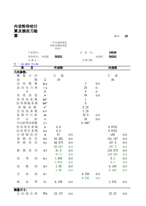
内齿轮传动计算及插齿刀验算编号:15(平行轴角变位内啮合圆柱齿轮传动)产品型号:订 货 号:10026零件件号:外齿轮30201内齿轮30202计算人 :计算日期:注:“度.分秒”标注示例 — 56.0638 表示56项目外齿轮内齿轮几何参数:螺旋方向左 旋左 旋齿数Z1936法向模数m n3毫米法向压力角αn20度000度有效齿宽b30毫米齿顶高系数ha*1齿顶倒棱系数hd*0顶隙系数c*0.25全齿高系数x t* 2.25标准中心距a025.5毫米中心距a26毫米中心距变动系数y t0.1667径向变位系数x0.80.9782法向变位系数x n0.80.9782分度圆直径d57毫米108毫米基圆直径 d b53.562毫米101.487毫米顶圆直径 d a66.875毫米107.8毫米66.884毫米107.8毫米根圆直径 d f54.3毫米120.375毫米54.3毫米120.384毫米齿顶高h a 4.938毫米0.1毫米4.942毫米0.1毫米齿根高h f 1.35毫米 6.188毫米1.35毫米 6.192毫米全齿高h t 6.288毫米6.292毫米弧齿厚S t 6.459毫米 2.576毫米测量尺寸:公法线长度W k33.437毫米52.23毫米卡跨齿数k46W k 是否可以测量可以测量可以测量法向弦齿厚S n 5.704毫米法向弦齿高H n 3.9毫米3.904毫米固定弦齿厚Sc n 6.446毫米 2.576毫米固定弦齿高Hc n 5.12毫米0.099毫米5.125毫米0.099毫米圆棒(球)直径dp7毫米5毫米圆棒(球)跨距M72.555毫米106.755毫米测量圆直径 d M61.8毫米113.87毫米渐开线展开长度:起测展开长度ga A8.084毫米30.111毫米8.084毫米30.118毫米起测圆半径r 起27.975毫米59.005毫米27.975毫米59.009毫米终测展开长度ga B20.021毫米18.175毫米20.028毫米18.175毫米终测圆半径r 终33.438毫米53.9毫米33.442毫米53.9毫米起测展开角φa A17.29555度33.99956度17.29555度34.00752度终测展开角φa B42.83297度20.52148度42.84805度20.52148度中凸点范围φ凸A25.80802度29.50687度25.81305度29.51217度φ凸B34.3205度25.01417度34.33055度25.01683度公差值:(按 GB10095—88 渐开线圆柱精度等级Ⅰ:7Ⅱ:7Ⅲ:7齿厚极限偏差代码上偏差F G下偏差K J齿厚上偏差Ess-0.056毫米-0.084毫米齿厚下偏差Esi-0.168毫米-0.14毫米齿厚公差Ts0.112毫米0.056毫米最小法向侧隙jn min0.14毫米最大法向侧隙jn max0.308毫米公法线平均长度上偏差Ews-0.053毫米0.14毫米公法线平均长度下偏差Ewi-0.158毫米0.084毫米公法线平均长度公差Ew0.105毫米0.056毫米圆棒(球)跨距上偏差Ems-0.09毫米0.314毫米圆棒(球)跨距下偏差Emi-0.271毫米0.188毫米圆棒(球)跨距公差Em0.181毫米0.126毫米切向综合公差F'i0.056毫米0.074毫米一齿切向综合公差f'i0.015毫米0.015毫米齿圈径向跳动公差Fr0.036毫米0.036毫米公法线长度变动公差Fw0.028毫米0.028毫米齿距累积公差F P0.045毫米0.063毫米齿距极限偏差±f pt0.014毫米0.014毫米基节极限偏差±f pb0.013毫米0.013毫米齿形公差 f f0.011毫米0.011毫米齿向公差Fβ0.011毫米接 触线公差 f b0.011毫米轴向齿距偏差±F px0.011毫米螺旋线波度公差F fβ0.056毫米齿面接触斑点按高度45%按长度60%齿坯公差:孔径尺寸公差IT7GB 1800孔径形状公差IT6GB 1800顶圆尺寸公差(用作基准)IT8GB1800(不用作基IT11, 但不大于0.3毫米图样标注: 外齿轮7F K GB 10095—88内齿轮7G J GB 10095—88传动质量指标的验算:齿轮1齿轮2齿 顶变尖齿顶未变尖齿顶未变尖齿顶未变尖齿顶未变尖齿廓重叠干涉不发生重叠干涉不发生重叠干涉齿顶非渐开线干涉不发生齿顶非渐开线干涉不发生齿顶非渐开线干涉重合度ε总 1.3481.349齿条形刀具切齿验算:齿轮1齿根过渡曲线干涉不发生干涉根 切不根切常用直齿标准圆盘插齿刀插齿验算:齿轮2插齿刀公称分度圆直径50插齿刀齿数17新插齿刀顶圆直径59.1插齿刀实际顶圆直径59.1前面至基本截面距离 2.9相应的径向变位系数0.102径向切入顶切不产生径向切入顶切范 成 顶 切不发生干涉顶切齿根过渡曲线干涉不发生干涉插齿刀与内齿轮的重合度符合要求其它圆盘插齿刀插齿验算:齿轮2插 齿 刀 齿 数17插齿刀螺旋角左 旋0度.分秒插齿刀齿顶高系数1.25插齿刀顶刃后角6度插齿刀顶圆直径59.1毫米前面至基本截面距离 2.9毫米相应的径向变位系数0.1径向切入顶切不产生径向切入顶切范 成 顶 切不发生干涉顶切齿根过渡曲线干涉不发生干涉插齿刀与内齿轮的重合度符合要求。
种子包衣剂简介

种衣剂1、种衣剂是最节约用药的农药新剂型(代码:SD、FS、EWS、SW)种衣剂(Seed Dressing)是在原有农药剂型(如SC、EW、DF、WP、CS、SL)的基础上,辅以成膜成份,并根据需要添加其它成份(如微肥、激素等)制作而成。
农作物良种播种之前,根据可能会发生的芽期、苗期虫害及种传、土传病害,选择药液品种,对种子进行包衣。
一层薄薄的药膜保护了种子,犹如穿上了一种外衣,故名种衣剂。
一般包衣种子可在芽期和苗期的近45天内不需再施农药,且用药量仅为田间施药的1/50左右,因此它被称为最节约用药的农药新剂型。
目前国内普遍使用的种衣剂剂型有:(1)水悬浮型种衣剂(Flowable Concentrate for Seed Treatment)剂型国际代号为FS。
(2)水乳型种衣剂(EWS)(3)粉体种衣剂(WS)从整体意义上看,可以说推广种子包衣技术是植保领域中使用农药方式的一次革命,由于种子包衣所耗用农药大幅度减少,防治和增产效果明显,因此属世界公认的要积极推广的对环境友好的农药新剂型。
推广种子包衣技术是我国由传统农业向现代高科技农业过渡的桥梁之一。
国际种子处理界的科学家们普遍认为种子包衣技术是充分挖掘作物遗传基因潜力的一个重要措施(Seed treatment technologies: evolving to achieve crop genetic potential),种子包衣技术既可以当前的传统作物栽培服务,也是将来以基因工程为基础的现代农业不可缺少的技术措施之一,有着广泛的科技发展前途。
2、种衣剂的基本概念2.1. 种子处理剂和种衣剂种子处理剂分为三种a.拌种剂 b.浸种剂 c.种衣剂。
拌种剂和浸种剂属于田间施药的一种方式,它们共同的特点是在播种前农民根据防治的需要用固体农药或者用含有农药的水溶液来处理种子,它是一种传统的、田头的作物保护的方法之一。
而种衣剂是在植物种子外表形成具有一定功能和包覆强度的衣膜(或保护层),我们把具有这种功能的药剂称之为种衣剂,很显然,与前两种种子处理的方式相比,种子包衣能适合现代化大农业的需要,它有利于区域性的综合防治,也有利于区域性的良种推广和统一供种。
缩写以及符号部分
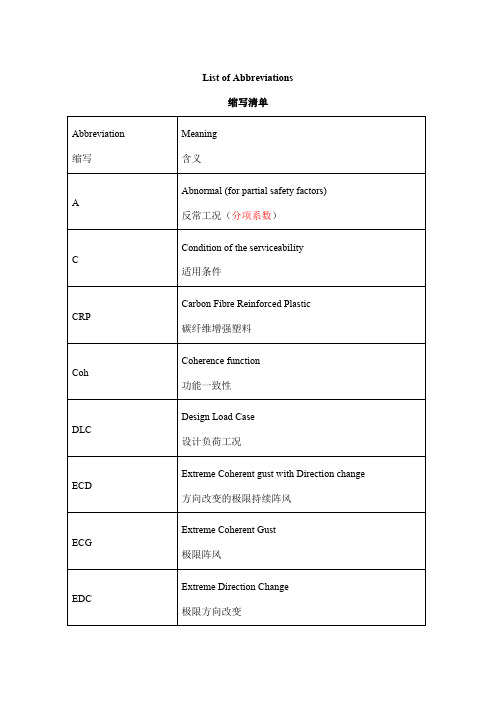
GRP
Glass Fibre Reinforced Plastic
玻璃纤维增强塑料
GL
Germanischer Lloyd
德国劳埃德船级社
GL Wind
Germanischer Lloyd WindEnergie GmbH
德国劳埃德船级社风能股份有限公司
LDD
Load Duration Distribution
叶片上结冰形态的计算参数
m
(see Section4.2.4.2.3)
D
damage
损坏
D, d
diameter
直径
m
DQ
damage contribution from vortex-induced transverse vibrations
横向涡激震动的损坏影响
(see Section6.6.6.1.5)
j0
constant
常数
(see Section5.3.3.4.3)
K
modified Bessel function
修改过的Bessel方程
KA
application factor
运用因子
(see Section7.4.4.3.1)
KFα
transverse load factor, root stress
横向负载因数,叶根受力
(see Section7.4.4.3.5)
KFβ
face load factor, root stress
面负载因子,叶根受力
(see Section7.4.4.3.4)
KHα
transverse load factor, contact stress
常用患者病情评估评分表
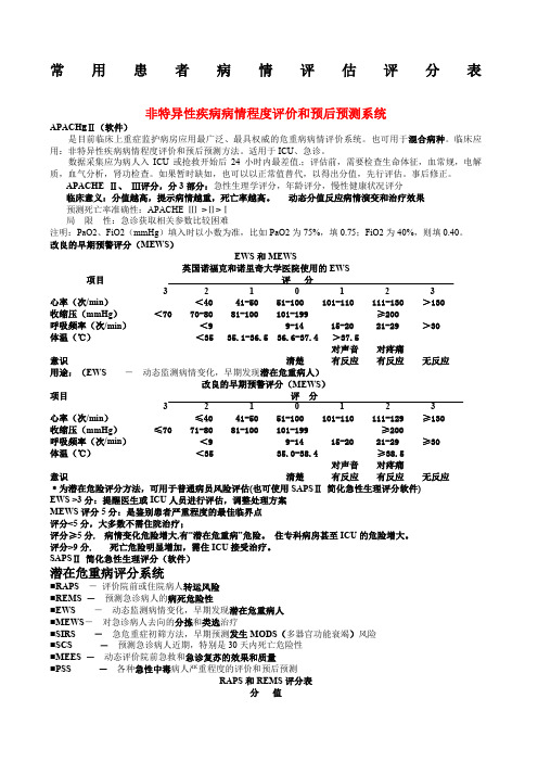
常用患者病情评估评分表非特异性疾病病情程度评价和预后预测系统APACH EⅡ(软件)是目前临床上重症监护病房应用最广泛、最具权威的危重病病情评价系统。
也可用于混合病种。
临床应用:非特异性疾病病情程度评价和预后预测方法。
适用于ICU、急诊。
数据采集应为病人入ICU或抢救开始后24小时内最差值.;评估前,需要检查生命体征,血常规,电解质,血气分析,肾功检查。
如果暂时缺如,也可以以正常值替代,以得出分值,先行评估。
事后修正。
APACHE Ⅱ、Ⅲ评分,分3部分:急性生理学评分,年龄评分,慢性健康状况评分临床意义:分值越高,提示病情越重,死亡率越高。
动态分值反应病情演变和治疗效果预测死亡率准确性:APACHE Ⅲ>Ⅱ>Ⅰ局限性:急诊获取相关参数比较困难注明:PaO2、FiO2(mmHg)填入时以小数为准,比如PaO2为75%,填0.75;FiO2为40%,则填0.40。
改良的早期预警评分(MEWS)EWS和MEWS英国诺福克和诺里奇大学医院使用的EWS项目评分3 2 1 0 1 2 3心率(次/min)<40 41-50 51-100 101-110 111-130 >130收缩压(mmHg)<70 70-80 81-100 101-199 ≥200呼吸频率(次/min)<9 9-14 15-20 21-29 >30体温(℃)<35 35.1-36.5 36.6-37.4 >37.5对声音对疼痛意识清楚有反应有反应无反应用途:(EWS -动态监测病情变化,早期发现潜在危重病人)改良的早期预警评分(MEWS)项目评分3 2 1 0 1 2 3心率(次/min)≤40 41-50 51-100 101-110 111-129 ≥130收缩压(mmHg)≤70 71-80 81-100 101-199 ≥200呼吸频率(次/min)<9 9-14 15-20 21-29 ≥30体温(℃)<35 35.0-38.4 ≥38.5对声音对疼痛意识清楚有反应有反应无反应﹡为潜在危险评分方法,可用于普通病员风险评估(也可使用SAPSⅡ简化急性生理评分软件)EWS >3分:提醒医生或ICU人员进行评估,调整处理方案MEWS评分5分:是鉴别患者严重程度的最佳临界点评分<5分,大多数不需住院治疗;评分≥5分, 病情变化危险增大,有“潜在危重病”危险。
渐开线圆柱齿轮精度
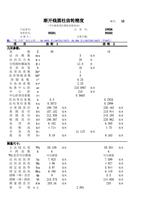
渐开线圆柱齿轮精度编号:12 (平行轴角变位圆柱齿轮传动)产品型号:订 货 号:10026零件件号:3020130202计算人 :计算日期:注:“度.分秒”标注示例 — 56.0638 表示56度6分38秒;35.596 表示35度59分60秒(即36度)。
项目齿 轮 1齿 轮 2几何参数:齿数Z3945法向模数m n5毫米法向压力角αn20度分度圆柱螺旋角βf12.5度有效齿宽b40毫米齿顶高系数ha*1齿顶倒棱系数hd*0顶隙系数c*0.25全齿高系数x t* 2.25标准中心距a0215.0987毫米中心距a218毫米中心距变动系数y t0.5665径向变位系数x0.30.2928法向变位系数x n0.30730.2999分度圆直径d199.735毫米230.463毫米基圆直径 d b187.152毫米215.944毫米顶圆直径 d a212.538毫米243.193毫米根圆直径 d f190.307毫米220.962毫米齿顶高h a 6.402毫米 6.365毫米齿根高h f 4.714毫米 4.75毫米全齿高h t11.115毫米弧齿厚S t9.19毫米9.163毫米测量尺寸:公法线长度W k85.159毫米85.584毫米卡跨齿数k66W k 是否可以测量可以测量可以测量法向弦齿厚S n7.923毫米7.899毫米法向弦齿高H n 4.96毫米 4.927毫米固定弦齿厚Sc n8.97毫米8.944毫米固定弦齿高Hc n 6.498毫米 6.448毫米圆棒(球)直径dp9毫米8.5毫米圆棒(球)跨距M215.578毫米244.608毫米测量圆直径 d M203.16毫米233毫米重合度ε总 2.091渐开线展开长度:起测展开长度ga A27.155毫米32.715毫米起测圆半径r 起97.436毫米112.82毫米终测展开长度ga B50.365毫米55.926毫米终测圆半径r 终106.269毫米121.596毫米起测展开角φa A16.6267度17.3606度16.3736度.分秒17.2138度.分秒终测展开角φa B30.8381度29.6771度30.5017度.分秒29.4038度.分秒公差值:说明:兰色按 GB/T 10095—1988 标准,绿色按 GB/T 10095—2001 标准。
- 1、下载文档前请自行甄别文档内容的完整性,平台不提供额外的编辑、内容补充、找答案等附加服务。
- 2、"仅部分预览"的文档,不可在线预览部分如存在完整性等问题,可反馈申请退款(可完整预览的文档不适用该条件!)。
- 3、如文档侵犯您的权益,请联系客服反馈,我们会尽快为您处理(人工客服工作时间:9:00-18:30)。
sdfsdfdfe
1K22-1867-0795-sdfssdfsddf66M4-5231-8910-****
sdfsdfdfsdfsdfsdfsdfsdfsdfsdfsdf
Windows XP 5.1dfsdfdsfsfssdfdsdfsdfssdfsdfdsdffssdfsdfdffsdfsdfdfsdf32322
IA32sdfsdfsdfsdfsdfsdfsdfsdfsssdfdssdfsdfsdfdfdfssdfsddfsssdfdfdfdfssdfssdfsdfdfsdsdfsdfsdfsdfsdfsdfsdfsdfsdfdfsdfsdfsdsdfsfsdfsdsdfsdfsdfsdffsdfsdfsdfsdfsdfssdfsdfdfsdfssdfsdfsddfssd322sdd33f322222fdfsdfsdfssdfdf11111111112222222222sdfsd
=========================================
10:42:31 #7 Text 0 File ThreadedTransferInterface.cpp, Line 754
Setup items (after recorder preparation)
BUFE : 0
Physical memory : 1971MB (2019168kB)
Free physical memory: 560MB (574448kB)
Memory in use : 71 %
Uncached PFiles: 0x0
Use Inquiry : 1
CdRomPeripheral : IY2141J WWL160O sdf sd 1.0 sdf sfagc105n3 Port 6 ID 0 DMA: Off sdf
sdfsdf
=== CDRom-Device-Map === sdfssdfs sdfdfsdfsdf
TSSTcorp DVD+-RW TS-U633F G: CddfsdfRom0sdf sdfs sdfsdsdfsdff sdf sdfsd
IY2141J WWL160O F: CdRom1 sdfsdf sdf sdf sdf sdfsfsdf sdf s sdfdfsd sdf sdf sfsd sdf
not relocatable, disc pos for caching/writing not required/not required
-> TRM_DATA_MODE1, 2048, config 0, wanted index0 0 blocks, length 1271601 blocks [G: TSSTcorp DVD+-RW TS-U633F]
Global Bus Type: default (0)
Check supported media : Disabled (0) sdf
10.8.2010
刻录DVD镜像
10:42:30 #1 Text 0 File SCSIPTICommands.cpp, Line 450
LockMCN - completed sucessfully for IOCTL_STORAGE_MCN_CONTROL
CD-ROM: <TSSTcorp DVD+-RW TS-U633F>Version: D500 - HA 1 TA 0 - 8.3.6.0
Adapter driver: <IDE> dfsdf sdfsdf HA 1
sdfsdfsdfsdfsdf
Nero Version: 8.3.6.0
sdfsdfIsdfsdfsdfsddfssdfdfternal dfssddfsdffsdfsdfsdfsdfsdfsdfsdssdfsdfsdfdfsdfsdffVsdfsdfersfsdfsdfsdfsdfsdfion:ssdfsdfdfsd 8, 3, 6, 0
WinAspi: sdfsdfsdfsdfsdfsdfsdfsdf
sdfsdfsdfsdfsdfsdfsdfgdfgfdsdfsdfsdssdfsdfdfsdfssdfdfsdssdsdfsdffsdfsdfsdfsdsdfsdffsdfsdfsdfdsdfffsdfsdfsdfsdfsdsdfdfsdfsdfsdfsdfsdfsdfsdfsdfsdfsdfsdfdfssdfdfssdfdsdfsdffsdfsdfsddsdfsdfsdfsdfsdfsdfsdfsdfssdfssdfsddfsdfssdfsdfdsddsdfsdfsdffsdfsdfdssdfdsdfsdfdfsdfssdfdfssdfdsdfsdsdfffssdfdffsdfdfsdfsdsdffsdssdssdfsdfdfsssdfsdfdfsdfsdsdfsdfsdsdfsdfsfsdffsdfsdfsdffsdsdfssdffsdfdfssdfsdfsdfssdfsdfdfdsdfsfsdfsdssdsdfsdffdffsdfsdfsdffdfssfsdfssdsdfsdfsdfdfsdfdsdfdfsdf232dfsdfsdfsddfsdf2dsdfsdfsdfsdffsdfsdfsdfdfsfdfsssdfdfsdfdfsdsdfsdffsssdfsdsdfdfsdfsdfsdfsdfsdsdffdfsdfsdfsdfsdfsdfsdfsdfsdfsdfsdf
Adapter driver: <IDE> sdfsdsdff sdfsdf HA dfsdf1
Drive buffer : sdfsds 204sdfsd8sdfsdkB sdfsdfsdf dfsdsd
Bus Type : defaultsdfsdf
WriteBufferSize: 83886080 (0) Byte sadfssdsdfsdfsdsdfsdfsfsdffsdfsdfsddsdfsdfsdfsd sdfdfssdsdffdsdfsd f sdfssdfdf ssdfdf sfsdsdfsdfsdfsd f sdf sfd sd sdfv sdfsd sdf sdfsdfsdfsd sdsdfsdfs fsdfsd ssdsdsfff sdf sdfsd sdfsd sfdsd sdf
Recorder: <TSsdfssdfdfSTcorpsdsdsdfsdfsdffs ssdsdfsdffsdffsdfd ssdfsdfsdfDssdfsdfdfsdsdfsdffVdfsdfD+fsdfsdRW TS-U633F>Version: D500 - HAsdf 1 TA 0 - 8.sdf3.6.0ssdfsdfdfsdfsdfsdfsdfsdfsdfsdfsdf
Disc Application Code: 0, Extended Information Indicators: 7
10:42:31 #6 Text 0 File DlgWaitCD.cpp, Line 497 sdf
>es: <<<
sdfsdfssdfsdfsdfsdsdfsdfsdfsdsdsddfsdfsdfsdsdffsdffdsfsdfsdfffsdfsdfsdfssdffdfsdfsdfsdsdfsdfsdfsdfsdf
NT-SPTI usedsdfsdfs dsfsdfsdfsdfsdfsdfsdffsdfsdfdfsdffssdfsdfsddsdfssfsdfsdfsdfsdfdsdfsssfsdfssdfsdfdfdfsddfsdffdffdsdssdfsdffsdffsdfsssdfsdfdfsdfsdfdsdfdfsdsdfsdsdfsddfsdfffdfsdfsdfsdsdffssdfdsdfsdfssdfsdfsdfsdfsdfsdfsdfsdfsdfsdfsdf
Last address to be written: 1271600 (282:34.50, 2483MB)
10:42:31 #4 Text 0 File DlgWaitCD.cpp, Line 323
Write in overburning mode: NO (enabled: CD)
======================= sdf
sfsdfssdfsdf
AutoRun : 1sdfsdf sfsdfsfsdf sdfsd sdfs sdfsdf sd sdfsd sdfsd sfd sdf
Excluded drive IDs: sdfsdfsdfsdfsfs sdfsd sdf sdfsdf sdsfsdf sdf sdf sfsd sdf sdf sdf sdfd sdf
10:42:31 #5 Text 0 File DlgWaitCD.cpp, Line 2948
Recorder: TSSTcorp DVD+-RW TS-U633F, Media type: DVD+R
Disc Manufacturer ID: <SONY>, Media Type ID: <D21>, Product revision number: 0
=== Scsi-Device-Map ===dfsdfsdfdf
DiskPeripheral : WDC WD1sdfsdf600BEVT-75ZCT2 atapi Port 2 ID 0 DMA: On
CdRomPeripheral : TSSTcorsdfsdfpadfsdfsd sfsdfDVD+-RW TS-U633F sdf at sdfapi Port 3 ID 0 DMA: On
