TestLink1.7RC3使用说明书
RC3 LOOP的使用说明
BOSS RC3 LOOP的使用说明一般使用:一插进OUT PUT A(而不是通常单块的INPUT),RC3就开始进入工作状态,因此我觉得它没有专门的BYPASS状态;红灯亮表示在录音,绿灯亮表示在播放。
两个音量旋钮就不用说了吧。
普通模式时(一般一开机就是普通模式),0、先选择你想播放或使用的音轨(1~99)编号,数字右下角如果带点的(比如1.)表示该编号已有录音,且绿灯会闪烁,表示正在读取记忆;不带点则该存储为空白1、设定拍速,根据你想要的拍速,以一定的时间间隔按几次TAP TEMPO,设定拍速,该按键会按你的拍速闪烁,同时播放节拍,此步骤可以省略,或者按一下RHYTHM停止节拍;RC3在你踩下踏板的瞬间开始录音(红灯亮),如果是已经有录音的(数字带点),则只是开始播放所选录音,如果之前没有设定拍速,这时TAP灯会在假设你弹奏了1、2、4、8、16……个小节的基础上,根据智能计算的拍速闪烁,但不会播放拍子。
2、再踩一下开始重复loop,同时继续保持录音状态(绿灯和红灯同时亮),另外两个节奏灯也开始按照一定拍速闪烁,这时可以继续弹奏叠加音轨,3、再踩一下录音状态结束(红灯灭),继续重复你已经弹奏、叠加的音轨。
此时2、3步骤可以一直重复,使你能不断叠加4、在播放的任何时候(不管红灯亮还是灭)踩住踏板2秒,屏幕会显示Un(Undo),此操作会删除你最近一次叠加的音轨,若想反悔,则再踩踏板2秒,屏幕显示Re(Redo),恢复刚刚删除的部分。
5、快速踩两次踏板,播放、录音都停止(但是设了拍速的话,TAP灯会继续闪),再踩则又从头播放。
如果在停止时踩住踏板2秒,则清除你刚刚已录下的所有段子,屏幕显示CL,此步骤不能恢复,但也只是删除临时内存里的,内置存储不影响,内置删除见7。
6、想要存储你已弹奏、叠加好的段子,就在停止播放时,先按一下WRITE,屏幕在Wr和数字之间闪烁,然后选择想存位置的数字编号,(此时可踩踏板取消存储步骤)再按一下WRITE,待屏幕、绿灯快速闪烁完后,存储完毕。
TestLink使用说明书(整理)

TestLink使用说明书版本<v0.1>目录1.系统介绍 (3)1.1系统整体结构 (3)1.2基本属于介绍 (4)2.登录 (5)3.用户管理 (6)3.1设置用户 (6)3.2角色和权限 (7)3.3给测试项目指派角色 (10)3.4给测试计划指派角色 (11)4.测试项目管理 (11)4.1新建一个测试项目 (11)4.2编辑/删除测试项目 (12)5.自定义字段管理 (13)6.测试需求管理 (15)6.1创建测试需求规格 (15)6.2创建测试需求 (15)7.测试用例管理 (16)8.测试计划制定 (17)9.测试执行 (18)10.指派给tester的用例 (19)11.测试结果分析 (20)12.其它易用性功能 (23)13.总结 (23)前言TestLink用于进行测试过程中的管理,通过使用TestLink提供的功能,可以将测试过程从测试需求、测试设计、到测试执行完整的管理起来,同时,它还提供了好多种测试结果的统计和分析,使我们能够简单的开始测试工作和分析测试结果。
TestLink 是开放源代码项目之一。
作为基于web的测试管理系统,TestLink的主要功能包括:•测试需求管理•测试用例管理•测试用例对测试需求的覆盖管理•测试计划的制定•测试用例的执行•大量测试数据的度量和统计功能。
1.系统介绍1.1系统整体结构TestLink系统共有三大基石:测试项目,测试计划和用户。
其它的所有数据都与这三大基石相关或者是它们的属性。
1.2基本属性介绍测试用例--通过测试步骤(动作,场景)和预期结果来描述一个测试任务。
测试用例是TestLink里最基本成分。
测试套件--测试用例的组织单元。
它构成测试规约的逻辑部分。
(测试用例集)测试规约--TestLink将测试规约拆分为测试套件和测试用例,他们将会在整个应用中长期存在。
一个测试项目只能包含一个测试规约。
测试计划--在你执行测试用例之前,需要创建一个测试计划。
rc71113使用说明书

INSTRUCTION MANUALMODEL RC71113For 1 player / Ages 8 and upP/N 82364000 Rev.BECAUTION•As with all small batteries, the batteries used with this game should be kept away from small children who might still put things in their mouths. If a battery is swallowed,consult a physician immediately.•Be sure you insert the battery correctly and always follow the game and battery manufacturer’s instructions. •Do not dispose of batteries in fire.•Batteries might leak if improperly installed, or explode if recharged, disassembled or heated.MAINTENANCE•Handle this product carefully.•Store this product away from dusty or dirty areas.•Keep this product away from moisture or extreme temperature.•Do not disassemble this product. If a problem occurs, remove and replace the batteries to reset the product, or try new batteries. Ifproblems persist, consult your warranty card for replacement instructions.RADICA:®GAMESTER ™DVD REMOTE AND “THE UNFAIR ADVANTAGE”ARE TRADEMARKS OF RADICA CHINA LTD.©2000 RADICA CHINA LTD.PRODUCT SHAPE™ALL RIGHTS RESERVEDPLAYSTATION IS A REGISTERED TRADEMARK OF SONY COMPUTER ENTERTAINMENT INC.•Use only the recommended battery type.•Do not mix old and new batteries.•Do not mix alkaline, standard (carbon-zinc) or rechargeable (nickel-cadmium) batteries.•Do not use rechargeable batteries.•Do not attempt to recharge non-rechargeable batteries.•Remove any exhausted batteries from the product.•Do not short-circuit the supply terminals.•Insert batteries with the correct polarity.Please retain this for future reference.This device complies with Part 15 of the FCC Rules. Operation is subject to the following two conditions: (1) this device may not cause harmful interference and (2) this device must accept any interference received, including interference that may cause undesired operation.WARNING:Changes or modifications to this unit not expressly approved by the party responsible for compliance could void the user’s authority to operate the equipment.NOTE:This equipment has been tested and found to comply with the limits for a Class B digital device, pursuant to Part 15 of the FCC Rules. These limits are designed to providereasonable protection against harmful interference in a residential installation. This equipmentgenerates, uses and can radiate radio frequency energy and if not installed and used in accordance with the instructions, may cause harmfulinterference to radio communications. However,there is no guarantee that interference will not occur in a particular installation. If this equipment does cause harmful interference to radio ortelevision reception, which can be determined by turning the equipment off and on, the user is encouraged to try to correct the interference by one or more of the following measures: •Reorient or relocate the receiving antenna.•Increase the separation between the equipment and receiver.•Connect the equipment into an outlet on acircuit different from that to which the receiver is connected.•Consult the dealer or an experienced radio TV technician for help.INTRODUCTIONCongratulations on choosing the Gamester DVD Remote, the ultimate DVD remote for the PlayStation 2 game console.CONTENTS1 x DVD Remote1 x Pass Through Port ReceiverIMPORTANT•Before using this product, read the PS2 Instruction Manual for safety, health and other information.•This product will only work with the PlayStation 2 game console.•Make sure you press the G/R button to select between the DVD Remote and Gamepad functions. When the DVD Remote function is selected, a green LED will appear on the Pass Through Port Receiver.BATTERY INSTALLATION1.Remove the cover of the battery compartmentby loosening the screw.2.Insert 2 x AAA batteries (we recommendalkaline) taking care to match the polaritycorrectly, as indicated within the batterycompartment.3.Replace the cover and tighten the screw. Do notover-tighten.Adult supervision is recommended whenchanging batteries.PRODUCT FEATURESSee figure 1 for the complete list of functions forthe DVD remote control.USING YOUR DVD REMOTE•Power down your PlayStation 2 and insert thePass Through Port Receiver into game controllerport 1 (see figure 2).•Turn on your PlayStation 2•Press the G/R button to select the DVD Remotefunction. When the DVD Remote function isselected, the green LED will appear on the PassThrough Port Receiver.•Insert a DVD.•When the on-screen menu appears, scroll downusing the DIRECTION keys and select the PLAYoption (see figure 3).•Press the ENTER key to confirm your selection.•You can access the on-screen menu at any timeby pressing either the SELECT key or the DVDMENU key at any time.USING YOUR PLAYSTATION 2GAMEPAD•Power down yourPlayStation 2 andplug yourgamepad into thePass Through PortReceiver (seefigure 4).•Turn on yourPlayStation 2.Select SubtitlesDVD MenuConfirm OptionPlay / PauseSkip One TrackBackFast RewindSelect betweenDVD function andthe controllerfigure 1Select AudioSelect TitleStop or CancelSelect (Returnto menu)Skip One TrackForwardFast ForwardDirection Keysfigure 2figure 3•Press the G/R button to select the GameController function. The green LED on the PassThrough Port Receiver will turn off when thisfunction is selected.TROUBLE SHOOTINGYour DVD Remote is not working.•Make sure the Pass Through Port Receiver isfirmly connected to the PlayStation 2 controllerport 1.•Make sure the DVD Remote function is selected.Press the G/R button to select the DVD Remotefunction. When the DVD Remote function isselected, the green LED will appear on the PassThrough Port Receiver.•Reset your PlayStation 2 game console.•Insert new batteries into the remote.Your gamepad is not working.•Make sure the Pass Through Port Receiver isfirmly connected to the PlayStation 2 controllerport 1.•Make sure the gamepad connector is firmlyconnected to the Pass Through Port Receiver.•Reset your PlayStation 2 game console.figure 4。
testlink使用详解
testlink角色无权限不可见该产品Guest只可以浏览用例Test designer可以维护关键字、需求、用例Seniortester可以维护关键字、用例、指派需求、维护构建【联系实际场景,这个角色最好是能够分配测试用例】Tester没有测试计划时与guest一样;有测试计划后则可以执行用例Leader在designer的基础上还可以维护平台(测试环境)、管理测试计划Admin除leader的所有权限,还可以维护角色权限、维护需求/用例自定义属性、维护需求/用例关键字、创建产品产品创建(admin)1、选择是否从已有的产品中创建a)是将复制已有产品中除执行结果外的所有信息b)否2、设置用例前缀,用例前缀用于改产品下所有用例名称的一部分,且将作为需求模块的一个查询条件3、平台中所有用户默认继承该产品的guest角色,可以为用户分配该产品的任意角色需求维护创建需求需求的状态可以是'有效的'或者'不可测试的'.不可测试的需求在结果分析时不被计入统计数据。
这个参数可以被用来设置不可实施的功能点或者错误的需求用例与需求关联1、需求的最小集合(叶子节点所在集合)层次上提供创建用例的功能实现方式为列出其所有子需求—>为需求项填写需要创建的用例数—>勾选需要创建用例的需求项-->点击创建用例—>提示哪些用例集、用例被自动创建-->继续创建用例2、自动创建的数据取值规则:a)用例集命名规则:需求集合名称(提示从需求规约创建)b)用例命名规则:需求名称【编号,每个需求生成的用例重新从1开始编号】c)用例摘要自动填充为“该用例是来源于哪条需求”,需求名称可以点击弹出该需求项,方便用例修改、编写时参照查看需求需求查看页面提供需求覆盖率这个属性,可以查看当前需求被哪些用例测试需求概览提供查看当前产品所有需求项覆盖率的功能需求覆盖率=实际关联需求项的用例数/需求项期望的用例数。
RC3说明书说课材料

RC3可编程步进电机控制器一.概述RC3可编程步进电机控制器是我厂采用新型的进口元件开发出的自动化控制设备,它可与步进电机驱动器、步进电机组成一个应用广泛的步进电机控制系统,能控制多台步进电机多段分时运行。
它广泛应用于各种工业控制场合。
按键采用轻触式开关按键,手感好,可靠性高,使用寿命长,面板上的按键有相对应得功能说明。
本控制器采用计算机式的编程语言,拥有输入、输出、计数、循环、条件转移、无条件转移、中断等多种指令,只需在控制器上按键选择指令和输入参数即可完成程序编程来控制电机运转和信号的输出以及被外部输入信号所控制,具有编程灵活、适应范围广等特点。
二.技术指标●可控制3台步进电机(任意两台电机同时工作)●可编250段程序指令(不同的工作状态)●9条升降速曲线供选择●脉冲最高输出频率:40KHz●8个输入,6个输出(一个继电器--10A触点,五个晶体管---1A,可直接驱动电磁阀)数码显示,可显示当前运行的指令名、计数次数、脉冲数●采用共阳接法,+5V输出,可直接驱动我厂的RC系列步进电机驱动器三.控制器的面板说明1.面板示意图2. 面板说明:12位数码显示:显示程序名,参数值,以及各种运行状态。
红绿指示灯:显示输入、输出、方向、脉冲等的工作状态。
操作键:多为复合键,在不同的状态下起不同的作用。
3.接线说明:具体接线可参考后面的完整流程。
(1)OPTO、DIR、PUL:步进电机驱动器控制线,采用共阳接线方式其中:OPTO 所有驱动器的公共阳端DIR1 0号电机方向电平信号PUL1 0号电机脉冲信号DIR2 1号电机方向电平信号PUL2 1号电机脉冲信号DIR3 2号电机方向电平信号PUL3 2号电机脉冲信号(2) 启动端,相当于面板上启动键。
(3)停止:等信号端,相当于面板上的停止键,再次按启动键后,程序继续运行。
停止端接线方式与启动端的接线方式一致。
(4)输入:通用开关量输入端(见开关量输入电路图)。
软件测试管理工具-TestLink使用说明书
TestLink使用方法目录1登录_________________________________________________________ 3 2初始配置(设置用户、产品) ______________________________________ 42.1设置用户_______________________________________________________ 42.2设置产品_______________________________________________________ 5 3测试需求管理_________________________________________________ 63.1创建测试需求规约_______________________________________________ 63.2创建测试需求___________________________________________________ 6 4测试用例管理_________________________________________________ 74.1创建组件_______________________________________________________ 74.2创建分类_______________________________________________________ 84.3创建测试用例___________________________________________________ 94.4建立测试用例和测试需求的覆盖关系______________________________ 11 5测试计划制定________________________________________________ 135.1创建测试计划(如集成测试阶段、系统测试阶段)__________________ 135.2创建里程碑____________________________________________________ 145.3构建管理______________________________________________________ 145.4定义用户/测试计划角色权限 ______________________________________ 155.5测试用例集____________________________________________________ 155.5.1添加测试用例到测试计划中__________________________________________ 165.5.2移去测试用例集___________________________________________________ 165.5.3显示最新的测试用例版本____________________________________________ 175.5.4设置测试用例的所有者______________________________________________ 17 6测试执行/报告bug: __________________________________________ 18 7测试结果分析________________________________________________ 197.1总体测试结果度量______________________________________________ 207.2查询度量______________________________________________________ 207.3全部构建的状态________________________________________________ 217.4失败的测试用例列表____________________________________________ 217.5阻塞的测试用例列表____________________________________________ 217.6未执行的测试用例______________________________________________ 227.7每个测试用例的执行情况________________________________________ 227.8图表__________________________________________________________ 227.9基于需求的报告________________________________________________ 22 8关键词的使用________________________________________________ 238.1创建关键词____________________________________________________ 238.2指派关键词____________________________________________________ 238.2.1指派好关键词,按关键词来搜索测试用例。
TestLink介绍与使用
Senior Tester:允许编辑测试规范、关键词、 需求以及测试执行和创建发布 ; Leader:允许编辑测试规范、关键词、需求、 测试执行、测试计划(包括优先级、里程 碑和分配计划)以及发布 ; Admin:一切权力,包括用户管理 ;
欧姆龙贸易(上海)有限公司
TestLink支持的测试用例的管理包含二 层:分别为新建测试用例集、创建测试用 例。可以把测试用例集对应到项目的功能 模块,测试用例则对应着具体的功能。我 们可以使用测试用例搜索功能从不同的项 目、成百上千的测试用例中查到我们需要 的测试用例,并且还提供移动和复制测试 用例的功能,可以将一个测试用例移动或 复制到别的项目里,勾上自动更新树选项, 欧姆添龙贸加易、(上删海)除有限或公司编辑测试用例后更新树会被
TestLink 是sourceforge开放源代码项目 之一。作为基于web的测试管理系统, TestLink的主要功能包括:
欧姆龙贸易(上海)有限公司
TestLink主要功能:
测试需求管理 测试用例管理 测试用例对测试需求的覆盖管理 测试计划的制定 测试用例的执行 大量测试数据的度量和统计功能。 接下来详细地介绍使用TestLink1.7进行测试 管理的完整过程 :
欧姆龙贸易(上海)有限公司
点击该页面右侧的“新测试用例”按钮, 弹出新建测试用例的窗口,如下图所示:
欧姆龙贸易(上海)有限公司
6.测试计划用例管理
6.1 添加测试用例到测试计划中 在主页通过测试计划下拉列表,选择一
个测试计划,点击测试用例集下的添加测 试用例到测试计划中按钮,进入向测试计 划中添加测试用例。点击一个测试用例集, 可以看到该测试用例集下的所有测试用例, 选择该测试计划中要执行的测试用例,也 可以根据版本下拉列表来选择该测试计划 下需要执行的测试用例版本。选择好后, 点击“增加选择的测试用例”按钮,可以 欧姆将龙贸选易择(上好海)的有限测公司试用例分配给该测试计划。
TestLink使用说明书(整理)

TestLink使用说明书版本<v0.1>目录1.系统介绍 (3)1.1系统整体结构 (3)1.2基本属于介绍 (4)2.登录 (5)3.用户管理 (6)3.1设置用户 (6)3.2角色和权限 (7)3.3给测试项目指派角色 (10)3.4给测试计划指派角色 (11)4.测试项目管理 (11)4.1新建一个测试项目 (11)4.2编辑/删除测试项目 (12)5.自定义字段管理 (13)6.测试需求管理 (15)6.1创建测试需求规格 (15)6.2创建测试需求 (15)7.测试用例管理 (16)8.测试计划制定 (17)9.测试执行 (18)10.指派给tester的用例 (19)11.测试结果分析 (20)12.其它易用性功能 (23)13.总结 (23)前言TestLink用于进行测试过程中的管理,通过使用TestLink提供的功能,可以将测试过程从测试需求、测试设计、到测试执行完整的管理起来,同时,它还提供了好多种测试结果的统计和分析,使我们能够简单的开始测试工作和分析测试结果。
TestLink 是开放源代码项目之一。
作为基于web的测试管理系统,TestLink的主要功能包括:•测试需求管理•测试用例管理•测试用例对测试需求的覆盖管理•测试计划的制定•测试用例的执行•大量测试数据的度量和统计功能。
1.系统介绍1.1系统整体结构TestLink系统共有三大基石:测试项目,测试计划和用户。
其它的所有数据都与这三大基石相关或者是它们的属性。
1.2基本属性介绍测试用例--通过测试步骤(动作,场景)和预期结果来描述一个测试任务。
测试用例是TestLink里最基本成分。
测试套件--测试用例的组织单元。
它构成测试规约的逻辑部分。
(测试用例集)测试规约--TestLink将测试规约拆分为测试套件和测试用例,他们将会在整个应用中长期存在。
一个测试项目只能包含一个测试规约。
测试计划--在你执行测试用例之前,需要创建一个测试计划。
RC07使用操作手册资料

长鑫盛通CC 呼叫系统RC07操作手册深圳市长鑫盛通科技有限公司地址:深圳市宝安41区甲岸路华丰大厦1601联系电话:400-0088-005修订历史记录版本说明审阅者修订者日期RC07 赵小丹2014-10-28目录目录 (3)(一)产品信息 (7)(二)概述 (8)2.1 用户介绍 (8)2.2 用户登陆 (8)2.3 用户界面 (9)(三)功能模块介绍 (10)一话务管理 (10)1.通话记录 (10)2 转移设置 (10)3 座席管理 (11)4 队列管理 (12)5 IVR按键记录 (12)二客户管理 (13)1 黑名单 (13)2 标记客户 (14)3 跟进记录 (14)4 预约登记 (15)6 资料转移 (17)7 资料管理 (17)三外呼管理 (17)1 自动外呼 (17)2 点击外呼 (19)3 语音外呼 (21)4 任务列表 (25)5 智能中继 (26)四系统状态 (26)1 活动通道 (26)2 状态管理 (27)五报表管理 (28)1 服务质检 (28)2 未接来电 (28)3示忙示闲记录 (29)4任务明细报表 (29)5座席话务报表 (29)六信息管理 (30)1 知识库 (30)2 公告列表 (31)七组织结构 (32)1角色管理 (32)2用户管理 (33)3部门管理 (33)4单位设置 (34)5 Logo修改 (35)八数据配置 (35)1重启服务 (36)2标签配置 (36)4重置授权 (37)5密码修改 (37)6防火墙设置 (38)7客户字段配置 (38)8弹屏方式设定 (39)(四)工具栏(顶部) (40)1通话记录 (40)2分机示忙 (40)3 通话保持 (40)4 通话转移 (41)5服务质检 (41)6座席界面 (41)7 注销 (42)(一)产品信息CC呼叫中心系统是我公司自主研发的新一代企业级呼叫中心系统。
该系统采用了最新的IP内核一体化设计,无须外挂任何其他设备、就能实现大容量的电话呼入/呼出处理、电话转接等传统 PBX 的所有功能,同时还提供了传统 PBX 所不具备的 VoIP 网关、来电智能分配、CRM 客户关系管理、电话录音、电话会议、语音信箱、通话报表等高端系统功能。
testlink帮助手册范本
Testlink使用手册目录简介 (1)1. system (2)1.1. 自定义字段管理 (2)1.1.1. 新建自定义字段 (3)1.1.2. 维护自定义字段 (5)1.2. 问题跟踪管理(Issue Tracker Management) (7)1.2.1. 设置问题跟踪管理系统 (8)1.2.2. 编辑问题跟踪管理系统 (11)2. 产品管理 (12)2.1. 测试项目管理 (12)2.1.1. 项目列表 (12)2.1.2. 维护项目 (14)2.2. 指派自定义字段 (20)2.3. 关键字管理 (22)2.4. 平台管理 (24)2.5. 设备(Inventory) (25)3. 产品需求 (26)3.1. 产品需求规格(Requirement Specification) (26)3.1.1. 产品需求规格操作(Requirement Specification Operations) (29)3.1.2. 产品需求操作(Requirement Operations) (36)3.2. 产品需求概览(Requirement Overview) (49)3.3. 查找产品需求 (50)3.4. 查找产品需求规格 (51)3.5. 指派产品需求 (52)3.6. 生成产品需求规格文档 (53)4. 测试用例 (54)4.1. 编辑测试用例 (55)4.1.1. 测试用例集操作 (58)4.1.2. 测试用例操作 (65)4.1.3. 维护测试用例 (70)4.2. 搜索测试用例 (81)4.3. Test Cases created per User (83)5. 测试计划 (83)5.1. 测试计划管理 (85)5.1.1. 创建测试计划 (85)5.1.2. 编辑测试计划 (88)5.2. 构建/版本管理(Builds/Releases) (88)5.2.1. 创建版本 (89)5.3. 编辑/删除里程碑(Milestone Overview) (91)5.3.1. 创建里程碑 (93)5.3.2. 编辑里程碑 (94)6. 测试执行 (94)6.1. 执行测试 (94)6.2. 指派给我的测试用例 (98)6.3. 测试报告和进度 (98)6.4. 进度仪表盘 (99)7. 测试用例集 (99)7.1. 添加/删除平台 (99)7.2. 添加/删除测试用例到测试计划 (100)7.2.1. 测试计划无版本、无平台 (101)7.2.2. 测试计划有版本、无平台 (103)7.2.3. 测试计划有版本、有平台 (105)7.3. 指派执行测试用例 (106)7.4. 设置测试用例的级别 (108)7.5. 更新测试用例的版本 (109)7.6. 显示最新的测试用例版本 (110)8. 用户 (110)9. Testlink中文翻译 (111)9.1. testcase/req comparison部分 (111)9.2. General terms (used wide)部分 (111)9.3. Status (used wide)部分 (111)9.4. gui/templates/inc_reqView.tpl (112)简介Testlink系统是sourceforge开发的源代码项目之一,作为基于web的测试管理系统,Testlink的主要功能包括:测试需求管理、测试用例管理、测试用例对测试需求的覆盖管理、测试计划的制定、测试用例的执行、大量测试数据的度量和统计功能。
ICOMR3说明书
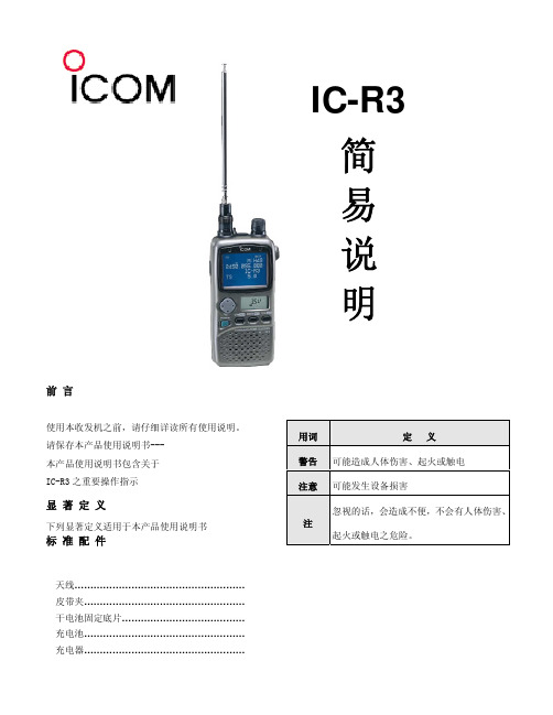
按键的名称
POWER
V/M(SKIP)
MODE(SET)
SQL(ATT) c
MULT
d
多重功能
旋转 DIAL 功能
短
按
长
按(0.5 秒以上)
VFO 模式
记忆模式
VFO 模式
记忆模式
将电源 ON/OFF
使成为 VFO 模式 使成为记忆模式
使成为 M-CH 选择模式
切换受信模式(电波模式)
使成为调整 TS 模式
快速操作表
操作内容 连续音编码(TONE)扫描的开始/结束
设定频道(上下端频道)
彩色液晶的 ON/OFF 切换彩色液晶的书面 调整音量 调整静音 受信显示 设定跳过无法收信的 TV 频道 叫出被设定为跳过的 TV 频道 重新设定方法 部份重新设定方法
按键操作
按 FUNC 再按 \ 长按开始短按结束 1. 长按 V/M(选择 M-CH 模式) 2. 按 FUNC 旋转 DIAL 即表示频道 3. 旋转 DIAL 按 FUNC 并长按c/d 按 FUNC 并短按c/d 按c/d(一直按的话会连续动作)
额定输出 背景亮度 OFF
省电模式
BP-206
1 小时 45 分
2 小时 10 分 25 小时 30 分
碱性电池 45 分
57 分
27 小时 30 分
镍镉电池 50 分
60 分
12 小时 50 分
上述规格如有变更,恕不通知亦不负责。
外观尺寸
: 61(W)×120(H)×32.9(D)mm
重量
: 300g
■接收
接收系统
: 三次变频*4
超外差
*4 在 1150Mhz 以下,四次变频在 1150Mhz 以上
归钜泉光电科技(上海) ATT7025 7027 单口编程器 说明书(210-SD-128)
ATT7025/7027单口编程器使用手册Tel: 021-********Fax: 021-********Email: sales@ Web: 目录1概述 (4)2适用范围 (4)3单口编程器配件 (4)4单口编程器功能 (4)5单口编程器硬件示意图 (4)6单口编程器原理框图 (5)7联机模式操作规程 (5)7.1硬件连接 (5)7.2PC端软件外观 (5)7.3操作流程(具体请看后面的图示说明) (6)7.4详细操作图示说明 (6)8脱机模式操作规程 (11)9编程中会出现的错误 (11)9.1第一类错误情况 (11)9.2第二类错误情况 (11)1概述单口编程器是针对ATT7025 / 7027在量产的时候编程使用的工具,电脑通过串口将用户需要下载的程序以及校验和传送到编程器内主控芯片的外部Flash中,当用户将需要烧写的目标芯片放入socket内的时候,通过点击编程器面板的红色按钮或者使用软件中的相应按钮,主控芯片会将其外部Flash中的数据烧写到目标芯片中,并计算校验和与之前存在主控芯片外部flash的数据比较,从而保证程序烧写的正确性。
2适用范围ATT7025 / 7027 系列芯片3单口编程器配件ATT7025/7027单口编程器硬件公-母串口连接线单口串行编程器软件单口串行编程器软件使用说明(在公司网站下载)AC-DC电源适配器:9V---12V4单口编程器功能支持使用PC对目标芯片编程支持脱机编程编程完成后自动校验5单口编程器硬件示意图6单口编程器原理框图7联机模式操作规程7.1 硬件连接将编程器与PC用串口线相互连接,接入AC-DC电源适配器,打开编程器电源,此时电源指示灯应该点亮,说明电源供电正常。
7.2 PC端软件外观(1) OpenPort ――― 打开串口(2) OpenFile ——― 打开一个Hex文件,以Bin文件的形式在左边窗口中显示(3) FlashErase ――― 擦除主控芯片的Flash(4) FlashWritten ――― 将要烧写的的程序内容写入主控芯片外挂的Flash内,同时会计算写入程序的校验码,并将其显示在Checksum1窗口,校验码是32K地址空间所有数据的累加和。
单通道无线接收器与双极态关闭器模块 RC613R 室内外使用,适用于泳池 浴池设备控制说明书

INSTALLATION OPERATION & SERVICE MANUALSINGLE-CHANNEL RADIO RECEIVER WITH DPST RELAYModel: RC613RFor indoor and outdoor use, suitable for Pool/Spa equipment controlELECTRICAL RATINGS: 20 A Resistive @ 120/240 VAC, 60 Hz; 1500 W Tungsten, 1 1/2 HP @ 120 VAC, 60 Hz; 3 HP @ 240 VAC, 60 HzNOTE: Neutral wire required for 120 AND 240 VAC applicationsGENERAL INFORMATIONTHIS DEVICE COMPLIES WITH FCC RULES PART 15. Operation of this device is subject to the following two conditions 1) This device may not cause harmful interference. 2) This device must accept any interference that may be received, including interference that may cause undesired operation. FCC rules prohibit adjustments to or modification of receiver and transmitter circuitry except for replacing the remote control battery. THERE ARE NO OTHER USER SERVICEABLE PARTS.This Heavy Duty Modular Radio Receiver is one-half of a two-part remote-control system. It operates as an ordinary ON/OFF switch but also responds to the signals of a hand-held transmitter - the other half of the system. The module is designed for indoor or outdoor use, can control 120 or 240 VAC loads, and can handle a variety of residential switching applications. By the push of a button on the face of the transmitter, the user is able to turn ON/OFF the connected load (lights, pump, etc.) from a remote location*, safely and conveniently. In addition, a single RC939 transmitter can operate up to three receivers and is able to “teach” each module a different code. (Transmitters are sold separately).The module consists of a receiver unit and a relay box permanently connected together with a seal between them. The receiver unit is welded and has no user serviceable parts inside. The relay box has two compartments, one for the 120 volt coil, double-pole relay and the other for making the field connections.* The open field range is approximately 100 feet, but depends on many factors like the age of the battery, proximity of large metal objects, the location of the receiver and environmental conditions at the time ofUSEFUL INFORMATION1. M ust be mounted upright. Antenna must be up.2. R adio receivers are sensitive to heat. Avoid mounting themabove heaters, air conditioners or exposed to afternoon sun.3. T he higher the receiver module, the longer its range. Forgood range and reliable reception, install modules as high aspractical above ground level with the antenna at top.4. L arge metal objects divert radio signals. Avoid mountingreceiver modules on metal walls, fences or near large metalobjects.5. E nvironmental conditions could effect the operation of theremote-control system. For example, in rain the range maybe less than normal.6. Celectronic gas heater igniters emit radio signals and caneffect the function of the receiver module. Avoid mountingmodules near such equipment.7. T o prevent electronic interference, install receiver modules atleast 3 feet apart.Make sure the intended load is within the capacity of the module, see ratings on page 1.1. T his module can be used to control either a 120 or 240 volt load.The NEUTRAL, however, must always be connected to the WHITE lead of the module. Refer to wiring diagrams on page 3.2. S elect the proper location (see Useful Information above) andinstall receiver assembly on a vertical surface or other support, using hardware suitable for the purpose.3. F ollowing wiring diagrams on page 3, make wire connections asshown.4. T urn ON power and test installation, using the ON/OFF button onface of the receiver module. Replace junction box cover, make sure the installation is secure.5. T o link transmitter button with the receiver, see operationinstructions on page 3.OPERATIONLinking an RC939 Transmitter Button with the RC613 ReceiverNOTE: The transmitter must be within 6 feet of the receiver during setup.1. O n the remote (RC939), use a paper clip to press and release the button on the lower right-hand side. The red LED onthe remote should be solid red now.2. O n the receiver (RC613), press and hold the blue CODE SET button for 3 seconds.3. N ow, with one-second intervals, tap the button that you want to program on the remote repeatedly until you hear therelay click inside the receiver. (Press at least 7 times) 4. N ow press a different button on the remote to save your setting. (Red LED should go out)5. T est the button you just programmed. If it is not working, make sure the red LED on the remote is off and go back tostep 1.Note: To clear any existing codes, press and hold the blue CODE SET button on the receiver for 20 seconds, then release. (This will eliminate all stored codes)Linking Multiple Transmitters with a ReceiverUp to three different transmitters can control a receiver. Follow steps 1 through 5 above for linking each RC939 transmitter with the RC613 receiver.Excluding a Transmitter Button Link from a ReceiverFollow this procedure to exclude a transmitter button from a receiver:1. With a stylus or paper clip, press the button on the side of the transmitter until the red LED illuminates.2. Momentarily press the configured ON/OFF button on the transmitter that you want to exclude from the receiver.3. Momentarily press one of the other buttons on the transmitter. The red LED on the transmitter turns OFF.4. M omentarily press the button you wanted to exclude to verify it no longer controls the receiver. The button is now excluded.LIST OF AVAILABLE MODELS AND COMPONENTSModelDescriptionRatings (60 Hz)RC613Single-Channel Receiver15 A Resistive, 10 A (1200 W) Tungsten, 1 HP (16 A FLA) @ 120 VAC, Single-Pole Single-Throw ContactsRC613L Single-Channel Receiver with 36 in. Lead15 A Resistive, 10 A (1200 W) Tungsten, 1 HP (16 A FLA) @ 120 VAC, Single-Pole Single-Throw ContactsRC613R Heavy-Duty Single-Channel Receiver and Relay Assembly20 A Resistive - 120/240 VAC, 12.5 A (1500 W) Tungsten ,1 1/2 HP @ 120 VAC; 3 HP @ 240 VAC, Double-Pole Single-Throw ContactsRC9393-Channel Transmitter with replaceable CR2032 Lithium Battery1. NEUTRAL must always be connected to the WHITE LEAD.2. Ground connections are not shown.LIMITED ONE-YEAR WARRANTYIf within the warranty period specified, this product fails due to a defect in material or workmanship, Intermatic Incorporated will repair or replace it, at its sole option, free of charge. This warranty is extended to the original household purchaser only and is not transferable. This warranty does not apply to: (a) damage to units caused by accident, dropping or abuse in handling, acts of God or any negligent use; (b) units which have been subject to unauthorized repair, opened, taken apart or otherwise modified; (c) units not used in accordance with instructions; (d) damages exceeding the cost of the product; (e) sealed lamps and/or lamp bulbs, LED’s and batteries; (f) the finish on any portion of the product, such as surface and/or weathering, as this is considered normal wear and tear; (g) transit damage, initial installation costs, removal costs, or reinstallation costs.INTERMATIC INCORPORATED WILL NOT BE LIABLE FOR INCIDENTAL OR CONSEQUENTIAL DAMAGES. SOME STATES DO NOT ALLOW THE EXCLUSION OR LIMITATION OF INCIDENTAL OR CONSEQUENTIAL DAMAGES, SO THE ABOVE LIMITATION OR EXCLUSION MAY NOT APPLY TO YOU. THIS WARRANTY IS IN LIEU OF ALL OTHER EXPRESS OR IMPLIED WARRANTIES. ALL IMPLIED WARRANTIES, INCLUDING THE WARRANTY OF MERCHANTABILITY AND THE WARRANTY OF FITNESS FOR A PARTICULAR PURPOSE, ARE HEREBY MODIFIED TO EXIST ONLY AS CONTAINED IN THIS LIMITED WARRANTY, AND SHALL BE OF THE SAME DURATION AS THE WARRANTY PERIOD STATED ABOVE. SOME STATES DO NOT ALLOW LIMITATIONS ON THE DURATION OF AN IMPLIED WARRANTY, SO THE ABOVE LIMITATION MAY NOT APPLY TO YOU.This warranty service is available by either (a) returning the product to the dealer from whom the unit was purchased or (b) completing a warranty claim online at . This warranty is made by: Intermatic Incorporated, Customer Service 7777 Winn Rd., Spring Grove, Illinois 60081-9698. For warranty service go to: or call 815-675-7000.SymptomPossible Cause(s)Corrective ActionNo response to ON/OFF button on receiver. (No click, controlled device does not operate.)No power to receiver black and white wires.Check for tripped circuit breaker at power panel. Verify that receiver is correctly wired.Faulty receiver.Replace receiver.Controlled device is always ON and can’t be turned OFF by the ON/OFF button on the receiver.Receiver is wired incorrectly.Correct per installation diagram.Faulty receiver.Replace receiver.Receiver clicks when its ON/OFF button is pressed, but the controlled device doesn’t operate.The controlled device is inoperative. Perhaps due to a switch, thermostat, etc. on the controlled device.Determine what is preventing the correctly powered device from operating.Receiver is wired incorrectly.Correct per installation diagram.Faulty receiver; never any voltage output from red wire.Replace receiver.Transmitter LED doesn’t light when buttons are pressed.Low battery.Replace CR2032 battery.Faulty Transmitter.Replace transmitter.Transmitter LED lights when buttons are pressed and ON/OFF button on receiver functions, but transmitter does not cause receiver to operate.Transmitter button(s) and receiver are not correctly linked.First, try all 3 buttons on (all) transmitter(s).Repeat the steps of “Linking RC939 Transmitterto RC613 Receiver” to correctly link the desired transmitter button to the receiver.Faulty transmitter and/or receiver.If possible, test with known good components, then replace as required.No response to transmitter signal some times.Weak battery.Replace battery.Appliance with brush type motor is in use.Relocate appliance and/or connect to another circuit.Other radio transmitter (police, etc.) is operating nearby.Link a different transmitter button with the receiver (see page 3, Operation instructions).Receiver is at edge of range.Mount receiver closer or higher.Insufficient Range.Weak battery.Replace battery.Antenna too close to ground.Relocate receiver module.Transmitter is held too close to ground.Hold transmitter at least 3 ft. above ground.Weak signal due to obstruction.Relocate receiver module.Nuisance operation.Other radio transmitter (police, etc.) is operating nearby.Link transmitter button with the receiver (see page 3, Operation instructions).Fluctuating supply voltage due to surge, etc.If frequent, install surge suppressor.Faulty receiver.Replace receiver module.Because of our commitment to continuing research and improvements, Intermatic Incorporated reserves the right to make changes, without notice, in the specifications and material contained herein and shall not be responsible for any damages, direct or consequential, caused by reliance on the material presented.INTERMATIC INCORPORATED。
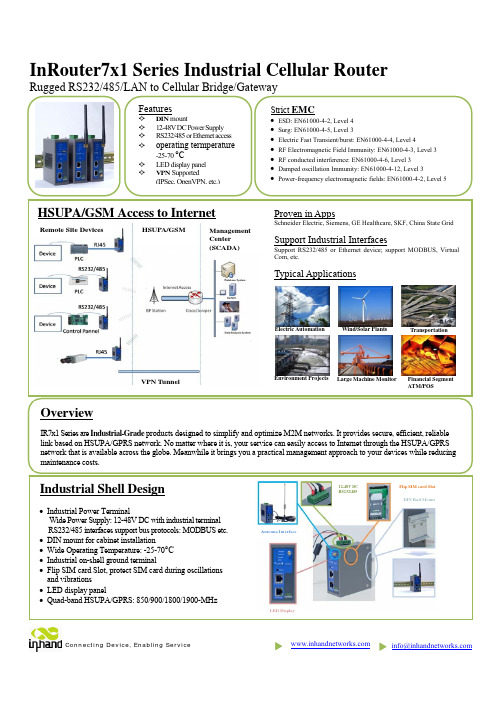
InRouter7x1系列工业级移动通信路由器产品说明书
***********************InRouter7x1 Series Industrial Cellular RouterRugged RS232/485/LAN to Cellular Bridge/GatewayFinancial Segment ATM/POSTransportationWind/Solar Plants Environment ProjectsOverviewIR7x1 Series are Industrial-Grade products designed to simplify and optimize M2M networks. It provides secure, efficient, reliable link based on HSUPA/GPRS network. No matter where it is, your service can easily access to Internet through the HSUPA/GPRS network that is available across the globe. Meanwhile it brings you a practical management approach to your devices while reducing Electric Automation HSUPA/GSM Access to InternetLarge Machine MonitorHSUPA/GSMManagement Center (SCADA)Remote Site DevicesVPN TunnelLED DisplayAntenna Interface12-48V DC RS232/485Flip SIM card Slot DIN Rail MountSpecificationsNetworksHSUPA/GSM Quad band(Global):850/900/1800/1900-MHz; Optional dual band (Asia) Authentication Protocol CHAP/PAP/MS-CHAP/MS-CHAPV2/etc. Dial On Demand Activated by Call/SMS /Local data Support APN Support enterprise private network service provided by mobile operator USB Modem (for IR7xxUE only) Please refer to "3G Modem Support List" to make sure your wireless modem is supportedPlatformCPU 200 MIPS ARM9 FLASH 8 Mbytes SDRAM 16 Mbytes O/S LinuxLAN Interface Auto-Adaption 10M/100M Ethernet auto-adaptive, MDI/MDI-X auto crossover Isolation Protection 1.5KV network isolation transformer protection Serial PortRate 1200bit/s~115200bit/sCommunication ParametersParity: None, Even, Odd, Space, Mark;Data Bits: 5,6,7,8; Stop Bits:1,1.5,2Protection 15KV ESD Protection SystemManagementConfiguration Serial, Telnet, and Web configurationUpgradeRemote upgrade and web upgrade, utilizing redundant backup mechanismfor worry-free upgradeNetwork FunctionsRouting Static routingMulti-Protocol SupportICMP, IP, TCP, UDP, DHCP, PPP, ARP, Telnet, DNS, SSH, VRRP, HTTP,HTTPS, etcConnection InspectionUtilizing self-developed connection inspection mechanism, ensuring thedevice is always on-lineNAT and PAT ,Port MappingNetwork Address Translation (NA T) and Port Address Translation (PA T),Deny illegitimate host access MAC Address Bundling Allow extranet user to access specific intranet port DDNSSupport Dynamic DNS (Domain Name System)Network Security VPNSupport standard IPSec (both support main mode and aggressive mode) Support PPTP/L2TP/GRE/SSL VPNFirewall Strategy State Packet Inspection(SPI), filtering multicast, filtering PING packet, preventing DoS attack, setting different firewall strategies Display Panel LED 3 LEDs Signal strength;4 Running Status LEDs: POWER, STATUS, WARN, ERRORPower Supply Power Input12~48VDC, anti-RCE, over-current protection; 5mm spacing industrial connectorPower Consumption 300mA @ 12V(max) Burst/Surge Protection 4KV/2KVOperation Environment Operation Temperature Industrial-grade: -25~70°C Storage: : -40~85°C Humidity5% - 95%, non-condensing Protection LevelIP30SafetyCertificationAnti-shock/ Drop/ Vibration IEC60068-2-27/ IEC60068-2-23/ IEC60068-2-6Electric StrengthDC500V imposed on communication lines to ground and on power lines to ground, resistance >500M ΩDimensions (mm)Pin Assignment5.00mm pluggable terminal blockOrdering InformationNetwork RS232 interface Without VPN RS485 interface Without VPN RS232 interface With VPN RS485 interface Without VPN RS232 interface With VPN RS485 interfaceWithout VPN GPRS (dual band)IR701GS37 IR701GS37-485 IR711GS37IR711GS37-485 IR791GS37 IR791GS37-485 GPRS (quad band) IR701GS55 IR701GS55-485IR711GS55IR711GS55-485 IR791GS55 IR791GS55-485 HSUPAIR701WH01 IR701WH01-485IR711WH01IR711WH01-485IR791WH01 IR791WH01-485 USB 2.0IR701UE IR701UE-485 IR711UE IR711UE-485 IR791UE IR791UE-485V+ 12-48V , power supply positive polarity V- 12-48V , power supply negative polarity NC None connect TXD/485- 232, 485- RXD/485+ 232, 485+ GND Digital groundSide View Guide Rail Front View Rear View Front-panel Installation Tool Installation ToolProduct KitStandard:AccessoriesDescriptionInRouter 700 Serials Wireless Router1Cable1 Cross line,CAT-5,1.5M Document and Software CD1Antenna5m Cellular AntennaPower SupplyPower Adapter, 100-265V AC in, 12V DC out (included in IR7xx)Power plug, American Standard(included in IR7xx)Optional Antennas:PictureTypeDescriptionGSM/GPRS Cellular AntennasGPRS Quad-band(included in IR7xxGS55)UMTS/HSDPA/WCDMA Cellular AntennasWCDMA Quad-band (included in IR7xxWH01) Anti-thief antenna WCDMA Quad-band(Optional for IR7xxWH01)Stick antennaWCDMA Quad-band(Optional for IR7xxWH01) Anti-thief antennaWCDMA Quad-band(Optional for IR7xxWH01)Contact usCopyright © 2010 InHand Networks, All rights reserved. Tel: 86-10-64391099-8022 Fax: 86-10-64399872Address: Wangjing Science Park, Road Lizezhonger, Chaoyang District, Beijing, P. R. C, 100102 Website: Email: ***********************。
PCLink 测试机联机系统使用手册
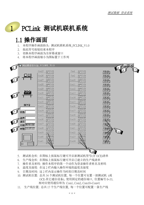
1PCLink 测试机联机系统1.1操作画面1.本程序操作画面抬头: 测试机联机系统_PCLINK_V1.02.按此符号按钮结束本程序3.切换本程序画面为全屏幕或窗口4.将本程序画面缩小为图标置于工作列5.测试机仓库:清单6.生产线仓库: 在图标上按鼠标左键可开启已建立的生产线清单7.操作者及密码: 操作本程序的第一个动作为登录操作者姓名及密码8.温度及湿度: 在这2栏内输入操作环境的温度及湿度9.日期及时间: 这2栏内显示操作当时的日期及时间10.测试机位置: 总共34个测试机位置, 每一个位置可安置一部测试机(或OCE-其它通信设备), 使用固定的通信端口, 位置编号0~33,相对应使用通信埠为Com1, Com2, Com10~Com4111.生产线位置: 总共17个生产线位置, 每一个位置可配置一条生产线43 111.2 操作者登录进入本程序后的第一个动作为操作者登录, 在还没有登录以前无法进行其它操作. 操作者被分为2个等级: [工程师] 与 [作业员], 一些有关于 测试规格, 测试机界面, 生产线配置 等属于系统性的操作, 本程序仅允许 [工程师] 等级的人员为之. 而操作人员的等级则依赖其登录的姓名及密码来辨识. 操作者登录的方法为:1. 将光标移到 [操作者] 字段, 在该栏内输入操作者姓名2. 按 [Enter] 键 或 将光标移到 [密码] 字段3. 在 [密码] 栏内输入操作者辨识密码(大小写不拘), 然后按 [Enter] 键4. 操作者登录后可再依 1.~3. 步骤再重新登录 (例如操作人员换班或变更等级等)姓名为 [系统管理员] , 密码为 [5207] , 等级为 [系统管理员]. 如果登录的操作者其等级为 [系统管理员], 则操作者名册将显示出来以供其编辑, 如下图:操作者名册的编辑方法:新增操作人员: 请在编辑区内输入新操作者的 等级, 姓名, 密码, 然后按 [新增] 按钮 (等级请用代号输入: 3=系统管理员, 2=工程师, 1=作业员) (姓名最长16个字符(中文8个字), 密码最长16个字符, 大小写不拘) 更新操作人员: 1. 请在显示区内用鼠标左键选取欲更新的操作者 2. 该操作者等级,姓名,密码将复制到编辑区, 修改后按 [更新] 按钮 删除操作人员: 请在显示区内用鼠标左键选取欲删除的操作者, 然后按 [删除] 按钮关闭窗口: 按 窗口右上角 X 符号关闭操作者名册窗口 (此为Windows 关闭窗口的操作 方式, 适用于本说明中的任何一窗口, 将不再重复说明)在操作者登录后, 测试机联机系统将恢复上次关机前联机状态, 例如下图:1231. 单一测试机TVS600W连接在COM1:2. 单一测试机TVS600W连接在COM2:3. 一部其它通信设备(O.C.E.) 连接在COM324. 第一条生产线名为“维明_SMD_FR105”由8部测试机所组成5. 第二条生产线名为“泰宏_ACL_1N4007”由5部测试机所组成测试机图标上所标示的符号代表测试机的通信状态, 稍后再介绍注: 其它通信设备(O.C.E.) 包括所有非测试机的其它通信装置, 例如: 自动送料机械(Handler)的通信界面等. 它们占用一个通信埠, 操作方式也很类似一部测试机, 但却具有各自不同的显示画面与通信格式, 而且不能加入生产线. 因此, 我们可以把它们视为一部“特别的单一测试机”1.3规格连结模式计算机传送到测试机:1.手动方式: 任何的规格变更, 均不自动传送到测试机, 也不显示讯息, 规格的传递须由操作者以手动方式操作2.自动方式: 任何的规格变更, 均自动传送到测试机, 且不显示讯息, 计算机与测试机之间随时保持着相同的测试规格3.仅显示讯息: 规格有变更时, 不自动传送到测试机, 但会显示讯息告知操作者4.确认后传送: 规格有变更时, 不自动传送到测试机, 但会显示确认窗, 等操作者确认后传送测试机传送到计算机:1.手动方式: 任何的规格变更, 均不自动传送到计算机, 也不显示讯息, 规格的传递须由操作者以手动方式操作2.自动方式: 任何的规格变更, 均自动传送到计算机, 且不显示讯息, 计算机与测试机之间随时保持着相同的测试规格3.仅显示讯息: 规格有变更时, 不自动传送到计算机, 但会显示讯息告知操作者测试机新建时其预设的双向传送模式均为“仅显示讯息”, 变更规格连结模式可以在测试机画面上操作, 或者整个生产线一次操作, 操作方式请看后面章节. 另外, 测试机传送到计算机并不提供“确认后传送“的模式. 如果规格连结模式设定为”仅显示讯息“或”确认后传送“则计算机与测试机初次联机完成, 或者规格有变更时, 将会显示如下图讯息窗:121. 确认是否传送规格之讯息窗2. 规格变更讯息窗1.4 测试机新建与移除新建测试机的步骤:1. 将光标移到 [测试机仓库] 图标上, 按鼠标左键, 开启新测试机清单2. 选取一测试机型号, 此时 [测试机仓库] 图标上方会显示该测试机型号3. 将光标移到 [测试机仓库] 图标上, 按着鼠标左键不放, 将它拖到连接该测试机通信埠空的 [测试机位置] 然后放开鼠标左键4. 该空的 [测试机位置] 将建立一个测试机图标,并标示其型号 移除测试机的步骤:1. 将光标移到欲移除的测试机的测试机图标上, 按着鼠标左键不放, 将它拖回 [测试机仓库] 然后放开鼠标左键2. 在该 [测试机位置] 上的测试机图标将会消失注: 其它通信设备(OCE)的新建与移除, 其操作步骤如同测试机新建的测试机其所有设定值将被清除为默认值, 且测试机图标将依其通信端口的状态有所不同:1. (?) 该通信埠可以使用, 但尚未和计算机完成联机2. (无特殊符号) 该通信端口可以使用, 而且已和计算机完成联机3. (X) 该通信埠无法使用 (例如未安装Moxa 通信卡, 或被其它程序占用)4. 测试机型号7. 非空的测试机位置1 2 37 85. 测试机仓库8. 空的测试机位置6. 新测试机清单测试机被移除后, 该测试机储存在数据库里的各项规格也一并被移除, 除非操作者先前曾以该测试机的规格储存为样本规格, 否则将丧失其所有规格设定值. 因为再重建一部测试机时, 其规格将被清除为默认值. 所幸新测试机之预设传送规格模式为“仅显示讯息”如果测试机内仍保有原来规格, 还可以将它读回来.1.5测试机的规格结构测试机的规格结构包括3大部份:1.测试规格: 测试材料特性的规格, 例如IF=1.000A, VR=800V 等2.机械界面: 和自动送料机械(Handler)的界面, 例如拨爪移位, 各Bin的拨爪输出等3.测试报表: 打印测试报表所需的资料, 例如取样类别, 取样率, 数据档名等其中[测试报表] 的各项设定仅储存于计算机的数据库中, 而[测试规格] 与[机械界面] 则同时存在于计算机的数据库与测试机的内存中. 其中[机械界面] 的设定值与自动送料机械有绝对的关系, 一旦测试机被安装在自动送料机械的某一站且配线完成, 则其[机械界面] 的设定值也大都固定了. 这些设定值几乎只对该测试站有意义, 换句话说, 当此测试机被移到另一测试站, 或者此测试站更换了一部新的测试机, 测试机内存的机械界面可能就无法适用, 而必须重新设定. 所以, 本程序把[机械界面] 留在站上, 也就是说当我们修改某测试机的机械界面设定时, 实际上是对该测试站进行设定, 当此测试机被移到另一测试站时只带走[测试规格], 而[机械界面] 则使用新站原先的设定, 至于本站的机械界面则留在本站, 以供新建或其它移进来的测试机使用.同样的, [测试报表] 的设定也是和测试站比较有关系, 在一条生产线的某几站我们仅监看其测试值, 某些站抽样, 某些站要打印测试报表等等. 所以我们也把[测试报表] 留在站上.综合以上, 在测试机联机系统操作下, 一部测试机在工作时接受3大部份的设定值: [测试规格] , [机械界面], [测试报表] (我们可以在测试机各页画面上看到这些设定值) , 其中[测试规格] 是真正属于测试机的, [机械界面] 和[测试报表] 则是属于测试站的.在某些特殊的情况下, 或许我们想让所有的规格设定(包括测试规格,机械界面,测试报表等)都完全属于测试机, 而不想部份使用测试站上的设定值. 本程序亦提供这样的功能, 在每一部测试机的[规格管理] 画面里有2个选项:☐测试规格内含[机械界面]☐测试规格内含[报表数据]只要在复选框上打勾, 即可让测试机从测试站上复制一份设定值而为其所专有, 后续的操作, 修改设定值等, 也都是针对测试机所专有的[机械界面] 或[测试报表] 做为对象的. 为了区分这两者的不同, 我们给它不同的名称:固定位置[机械界面] 与测试机内含[机械界面]固定位置[测试报表] 与测试机内含[测试报表]当我们想取消测试机内含[机械界面]或[测试报表]时(恢复使用固定位置的设定值), 只要取消复选框的打勾即可, 但是会发生一个问题: 测试机内含一套设定值, 固定位置也有一套设定值, 这两套设定值可能不同, 如今要放弃内含设定值使用固定位置设定值, 是否要先将内含设定值复制到固定位置再使用呢? 计算机不知道您要如何决定, 所以将会有一个讯息窗来询问您.1.6测试机移动位置不论是单一测试机或者是生产线上的测试机, 您都可以移动它们的位置, 这样做的意义是, 使用另一个通信埠或变更测试机在生产线上的测试站, 其方法为:1.将鼠标光标移到非空的测试机位置上的测试机图标上2.按住鼠标左键不放3.将测试机图标拖到新的空的测试机位置, 然后放开鼠标左键注: 其它通信设备(OCE)也可以移动位置, 其操作步骤如同测试机1.7测试机画面我们将测试机的各项规格设定, 测试读值, 操作按钮等依其性质划分为5类, 放置于5个显示页中, 构成测试机画面. 这5页分别为[测试], [分类条件], [机械界面], [规格管理], [测试报表]. 其中后2者为计算机专有的画面, 而前3页在测试机的显示器上也会有类似的画面以供设定操作. 在本程序中, 我们尽量把测试机画面规划得和测试机所显示的类似, 以避免操作者困扰. 不同型号的测试机因其不同的测试规格, 其画面也不完全相同, 要显示测试机画面, 请:1.将鼠标光标移到非空的测试机位置的测试机图标上2.按一下鼠标左键, 可显示该测试机画面3.将鼠标光标移到各页卷标, 按一下鼠标左键, 可显示该页画面底下各节将以TVS600W 测试机为范例, 分别介绍各页画面1. 换页卷标2. 当按键不能被操作时(例如尚未与测试机完成联机), 以较淡颜色的失效状态显示注: 不同的其它通信设备(OCE)各具有不同的显示画面, 要显示其画面时, 请在其图标上按一下鼠标左键(如同测试机操作一般)1.7.1 测试机 [测试] 画面1. 测试规格设定2. 手动测试按钮, 其功能和测试机面板按键相同3. 测试读值队列操作区4. 测试读值显示5. 计数器及计数器归零按钮A. 测试读值分布图操作每一个测试读值的显示字段(只要能显示测试结果的)都能建立一个分布图, 实时在画面上显示材料分布及分析值. 由于此项功能, 本程序须将测试读值作进一步的操作与处理, 比较耗时, 在测试读值全部写档的情况下将显得比较没有效率(降低可收台数), 所以测试机的默认值是不在任何字145段建立分布图的, 我们也建议除非有必要是不须在字段建立分布图. 一旦某一字段建立了分布图, 将被记录到数据库, 直到该分布图被删除为止1. 分布图2. 建立分布图的字段, 以黄色显示3. 测试读值显示字段的菜单4. 分布图格式设定新建立(或重建)分布图的方法:1. 将光标移到欲建立分布图的测试读值显示栏内2. 按鼠标右键, 显示 [分布图菜单]3. 用鼠标左键在 [分布图格式] 项目上按一下, 以显示 [分布图格式设定] 窗口4. 在 [分布图格式设定] 窗口画面上设定分布图格式5. 按 [建立新分布图] 按钮分布图格式设定说明:1. 分布图名称: 显示在分布图上的抬头名称2. 图左端坐标: 分布图最左端的坐标值3. 图右端坐标: 分布图最右端的坐标值4. 线条间距值: 分布图上相邻两线条间距, 必要时本程序会依左右两端坐标的分辨率修正之2345.纵轴模式: 设定分布图的纵轴单位为计数值(个数)或百分比6.数据来源: 取样材料: 被取样的测试读值才加入分析所有材料: 不论测试读值是否被取样全部加入分析所有DUT测试值: 对于一个材料内含数个待测组件(例如一个桥式整流子内含4个待测二极管), 指定是否将相同测试项目(例如VF)画在一张分布图上.此核取栏如打勾, 则相同测试项目将画在一张分布图上, 以桥式整流子为例, 一次测试分布图上即有4笔VF数据. 此核取栏如空白, 则仅建立分布图的字段的数据被加入分析(一次测试1笔数据). 如一个材料内仅含一个待测组件, 则此核取栏将失效7.按钮操作: 建立新分布图: 新建分布图或重建分布图(旧图内的数据将全部被清除)删除: 删除分布图, 仅该字段已建立分布图时此按钮才有效取消: 取消分布图格式设定, 并关闭此窗口画面分布图菜单:1.将光标移到测试读值显示栏内, 按鼠标右键, 可显示[分布图菜单]2.数据来源为[所有DUT测试值] 的分布图可由任一字段来操作此菜单3.分布图格式: 新建或重建分布图, 或查看分布图格式4.删除分布图: 删除分布图, 仅该字段已建立分布图时此选项才有效5.显示分布图: 测试机画面在前景工作时可能会掩盖分布图, 可用此按钮显示之, 仅该字段已建立分布图时此选项才有效. 如果要显示测试机的所有分布图请用[测试机菜单] 来操作, 稍后介绍分布图说明:1.个数: 加入此分布图的数据个数, 包括超出分布图左右坐标以外的个数2.最小/最大: 加入此分布图的数据的最小值与最大值(Minimum & Maximum)3.平均值: 加入此分布图的所有数据的样本平均值(Sample Mean)4.标准差: 加入此分布图的所有数据的样本标准差(Sample Standard Deviation)5.您可以搬移分布图的位置, 然后按右上角的X 符号关闭(非删除)分布图, 则此分布图的位置将被记录到数据库内, 下次此分布图再显示时, 会在您所指定的位置上1.7.2测试机[分类条件] 画面本页为[分类条件] 的设定, 用来规范各类别(Bin)的测试读值上下限, 其中各字段设定值的意义和测试机相同, 请参阅测试机使用说明1.7.3测试机[机械界面] 画面本页为 [机械界面] 的设定, 用来设定光藕合器触发测试的动作, 以及拨爪驱动的移位数及输出动作:1. [机械界面] 的各栏设定值及显示值其意义和测试机相同, 请参阅测试机使用说明2. 设定字段后面的(括号附注)为有效的输入值范围3. 本页画面内多开一栏 [界面说明], 可让操作者加注此机械界面的说明1.7.4 测试机 [规格管理] 画面1. 远程操作测试机内的规格存取2. 测试机辨识资料3. 测试规格编号与说明4. 测试规格结构5. 规格档案操作6. 规格连结模式7. 手动传送测试规格8. 远程控制测试机的键盘操作更新后的Datalogging操作1.打开电脑, 进入Datalogging系统.2.在操作者中输入用户名和密码。
SkylinkHome 一键到三按键遥控器操作方法指南说明书

1-Button Remote 2-Button Remote 3-Button RemoteModel LK-318-1Model LK-318-2Model LK-318-31-Button Transmitter LK-318-12-Button TransmitterLK-318-23-Button Transmitter LK-318-3ButtonsRed LED Thank you for your purchase of a SkylinkHome TM Remote, Model LK-318-1/ LK-318-2 / LK-318-3. This remote which is also called transmitter in this document allows you to wirelessly operate SkylinkHome TM receiver modules.All wireless signal communications within the SkylinkHome TM system are based on rolling code technology to ensure highest security is used. The following items are included in this package:- One of LK Series Remotes- Lithium Battery CR-2032 (Installed)- User’s Instructions2. POWER UPTo power the transmitter, simply remove the battery isolator from the transmitter, red LED will flash once. Press the button on the transmitter, the red LED should flash. The transmitter is now powered properly. If the red LED does not flash when button is pressed, refer to Section 6 “Battery” of this manual.1) Remove isolator, 2) LED on for 1 secondIn order to operate the receiver module remotely with a transmitter, it must be programmed to the receiver module.To program a remote to the receiver module, a “Learn” code must be transmitted, follow the instructions below to transmit the “Learn” code to the receiver.1. Put the receiver module that you plan to program into programming mode. Refer to the User’s Instructions of that receiver module.2. Press 1 and 2 simultaneously and hold for 2 seconds until the LED changes from on to flashing quickly. Release the buttons. The red LED on the transmitter will be on for 15 seconds.3. Press the button on the remote that you plan to use when the LED is steadily on to transmit the “Learn” code.4. Once the remote is programmed, the receiver modules will quit from programming mode and the programmed transmitter is ready to be used now. Learn CodeFollow steps 2 and 3 above to transmit the “Learn” code when programming the remote to receiver modules.You may follow the same instructions to program different buttons on the transmitter to different receiver modules.LED on for 1 secondPressing the programmed button on the transmitter once will toggle the status of the load that is connected to the receiver module, i.e. if the light is off, pressing the button turns on the light, and vice versa. When the programmed button is pressed, the red LED flashes briefly indicating signal is transmitting.Password protection (Only available for LK-318-3 (Not available for LK-318-1 or LK-318-2)The LK-318-3 can be password protected. If you enable the password protection, you can only operate LK-318-3 after you input the correct password.Password can be 2-8 digits long, which is a combination of 1, 2 and 3. For example, password can be 1, 2, 1, 2. To input this password, you have to press button [1], then [2], then [1], then [2].Note:[1] = Button 1 [2] = Button 2 [3] = Button 3Note:The time-out period is 1 second during above password input.The factory default password is 2, 2, 2, and this password function is disabled out of factory.Change password1. Press 1 and 3 simultaneously and hold for more than 10 seconds until the LED changes from flashing quickly to flashing slowly.2. Input old password.3. Press 1 and 3 once simultaneously to confirm. If the password is wrong, the LED will flash 3 times and you have to start it over from step1.4. Input new password.5. Press 1 and 3 once simultaneously to confirm.6. Input new password again.7. Press 1 and 3 once simultaneously to RE-confirm. If the password is different from the one of step 4, the LED will flash 3 times and you have to start over from step 1. Otherwise, the password has been changed to the new one and the password protection is enabled.Disable password1. Press 1 and 3 simultaneously and hold for more than 5 seconds until the LED flashes quickly but not until the LED flashes slowly.2. Input old password.3. Press 1 and 3 once simultaneously to confirm. If the password is the password protection will be disabled.Enable password1. Press 1 and 3 simultaneously and hold for more than 2 seconds until the LED flashes quickly but not until the LED flashes slowly.2. Input old password.3. Press 1 and 3 once simultaneously to confirm. If the password is correct, the password protection will be enabled.You can toggle the two states - password protection enabled or disabled.Note:The time-out period is 15 seconds during any of the above setting opera-tions. After 10 seconds, the LED will flash 3 times and the remote will exit from setting.isolatorButton [1]Button [2]Button [3]If you forget your password and want to reset LK-318-3, follow the steps below:1. Press 1 and 2 simultaneously and hold for more than 15 seconds until the LED flashes.2. After you release 1 and 2, the LED will be turned off and LK-318-3 will be reset. The password will be reset to factory default.After the reset, password protection is removed but the remote can not control any receiver until you reprogram it to receivers you want to control.When the operating range is reduced, or when the red LED does not flash during operation, it is time to replace the battery.The transmitter is powered by a lithium battery CR-2032. Follow the instructions below to replace the battery to the transmitter.1. Undo the two screws on the back of the remote. The bottom case will then come off.2. Take out the old battery.3. Place the new battery in position.4. Close the cover and reinsert two screws.Note: Dispose of old battery promptly and properly.The device is approved by the FCC and it complies with Part 15 of the FCC Rules. Its operation is subject to the following two conditions : 1. This device may not cause harmful interference.2. This device must accept any interference that may cause undesired operation.WARNING:Changes or modifications to this unit not expressly approved by the party responsibleof compliance could void the user’s authority to operate the equipment.If, within one year from date of purchase, this product should become defective (except battery), due to faulty workmanship or materials, it will be repaired or replaced, without charge. Proof of purchase and a Return Authorization are required.If you would like to- find out the up-to-date specifications- know more about features and applications - download documents, i.e. user’s instructions - order Skylink productsor if you have difficulty getting products to work, please:1. visit our FAQ section at , or **********************************,or3. call our toll free at 1-800-304-1187 from Monday to Friday, 9 am to 5 pm EST. Fax (800) 286-1320The SkylinkHome TM System consists of many other devices such as SkylinkHome TM Remotes, Motion Sensor, ON/OFF Wall Switch, Wall Dimmer, Plug-In Dimmer with or without Repeater, Plug-In ON/OFF Control (Outdoor/Indoor), Screw-In Dimmer, ON/OFF/Dimming Control, ON/OFF Control, Smart Button TM Garage Door Control, etc. Please visit Skylink website at for more information.CUSTOMER SERVICE17 Sheard avenue, Brampton, Ontario, Canada L6Y 1J3Email:*********************** P/N. 101Y058Patent Pending© 2012 SKYLINK GROUPELithium battery CR-2032 included. (Positive side up)。
LINK USB无线模拟器控制器使用说明说明书

T urn on the power of the PC and connect the WSC-1 to the USB port of the PC.A setup complete message will be displayed and automatically recognized.Use the link button to link with the transmitter S-FHSS 2.4GHz system to be used.* When operating the link, bring the transmitter within 8 inches.1 Bring the transmitter and the receiver closeChecking WSC-1 on Windows Right-click the game controller icon (WSC-1) and click "Game Controller Settings" in the displayed menu.displayed on the controller (it may be displayed as 8-axis 0 button), and the status is displayed as "OK".Thank you for purchasing the WSC-1 Wireless Simulator Control for S-FHSS 2.4GHz System. This WSC-1 is a USB interface that enables the S-FHSS 2.4GHz system Futaba transmitter to be used wirelessly as a controller for Real Flight RF8 / 9 or later. (The S-FHSS 2.4GHz system Futaba transmitter can also be used as a game controller for Windows ®.)Mini screwdriverLink to the transmitterController settingsClick Settings ...1. Click the mark3. Click [Edit] buttonDisplayed as WSC-1 (Active)2. Click the FutabaClick Select Controller...To use it as a real flight controller, register the Futaba transmitter by following the steps below.Transmitter settingsS-FHSS 2.4GHz system When using the Futaba transmitter as a substitute for the real flight InterLink Controller, set the SW / VR functions of the transmitter after CH5 as shown in the figure.Click ControllerSet the Deadband Percentage (%) number to "0".2 or3 pos SWCH53 pos SW CH82 or3 pos SWCH7VR CH6After making changes to your controller profile, you will want to save all modifications. Note that you cannot make changes to stock profiles that are included with RealFlight. Click the [Save As] button to save the profile under a different name.Input (Example Mode change: Mode 2 to Mode 1)changing the stick movement from mode 2 to mode 1, first change the operating axis of the elevator channel. Channe l 2 -Elevator Click Input at the far right of the display. The Input Detection screen will be displayed. Operate the elevator stick in mode 2 of the transmitter. When the elevator settings are complete, you will be returned to the Edit Profile screen. Then perform the same operation on the throttle side. This completes the mode If you use mixing, dual rate, expo programmed on your radio.Enable Software Radio Mixes ------OFFEnable Software Radio Dual Rates and Expo ------OFF*In this case, SW / VR is not set using the AUX CH (AUX channel) function of the transmitter.*For detailed explanation, please read the instruction manual of RF8 / 9.If you need to change the direction of operation by operating a stick, switch, etc., click the check box of Reverse to add or remove the mark.Calibrationis necessary to calibrate the stick neutral position and operating range of the transmitter with [Calibration]. please read the instruction manual of RF8 / 9.1. Click the [Save As...] button.U n c h e ckand later versions, do not click Input for channels after Channel 7. If you click it, either the smoke ON / OFF switch or the throttle hold switch will not operate. click it, do not save it, close the screen, and try again.ThrottleElevatorMode 1Input Detection screenRF8 Edit ProfileRF9 Edit ProfileReverse:Change the operating directionInput: Change of operation stick, switch, etc.2. Enter a new name.3. Click the [OK] button.。
NAVITEK Active LAN Tester 产品说明书
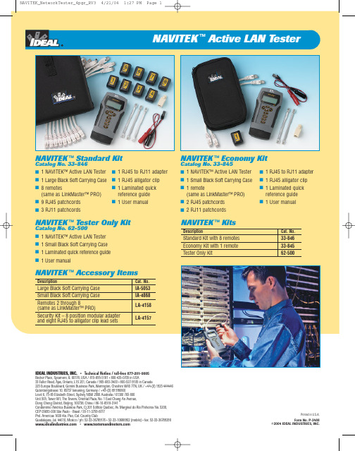
NAVITEK™Active LAN Tester■Comprehensive testing andtroubleshooting tool forstructured data networks■Verifies the integrity of thephysical network and validatesactive network connectivitywith PING and Hub blinking■Detects port services suchas Ethernet, ISDN, POTS,T oken Ring■Displays Ethernet networkspeed and capabilities■Performs length measurementup to 1500 feet (457.2 meters)■T ests both shielded andunshielded structured cableto T568A/B standards withfault identification■Supports four-tone generationfor cable tracing■Easy-to-read backlitLCD displayCompact ergonomic design enables complete active and passive network verification from NAVITEK ™Active LAN TesterComprehensive Network Verification and Testing…In the Palm of Your HandRJ45 Jack – on top of unit for easy connection to cable or jack.Back-lit LCD 2 lines by 16 characters with iconsBattery Cap – press down with heal of hand to openPWR Key – Press to turn on NAVITEK™ in the mode set at power off. Additional presses toggle the backlight on and off. Hold down to power off.modes, press NTWRK SEL Key – used to enter displayed operating mode, start a new test,change the value of an option,enter sub-menus or move to the next screen.Cursor Keys – Used to scroll through options, set addresses Back-lit LCD screen displays clear and concise information for easy reading.。
- 1、下载文档前请自行甄别文档内容的完整性,平台不提供额外的编辑、内容补充、找答案等附加服务。
- 2、"仅部分预览"的文档,不可在线预览部分如存在完整性等问题,可反馈申请退款(可完整预览的文档不适用该条件!)。
- 3、如文档侵犯您的权益,请联系客服反馈,我们会尽快为您处理(人工客服工作时间:9:00-18:30)。
TestLink 使用说明书版本<v0.1>目录1登录__________________________________________________________ 4 2初始配置(设置用户、产品) ______________________________________ 52.1设置用户 ___________________________________________________ 52.2设置产品 ___________________________________________________ 5 3测试需求管理__________________________________________________ 63.1创建测试需求规约 ____________________________________________ 63.2创建测试需求________________________________________________ 7 4测试用例管理__________________________________________________ 74.1创建组件 ___________________________________________________ 84.2创建分类 ___________________________________________________ 84.3创建测试用例________________________________________________ 94.4建立测试用例和测试需求的覆盖关系 ____________________________ 11 5测试计划制定_________________________________________________ 135.1创建测试计划(如集成测试阶段、系统测试阶段) _________________ 135.2创建里程碑________________________________________________ 145.3构建管理 __________________________________________________ 145.4定义用户/测试计划角色权限 ___________________________________ 155.5测试用例集________________________________________________ 155.5.1添加测试用例到测试计划中 ________________________________________ 165.5.2移去测试用例集_________________________________________________ 165.5.3显示最新的测试用例版本__________________________________________ 175.5.4设置测试用例的所有者____________________________________________ 17 6测试执行/报告bug: __________________________________________ 18 7测试结果分析_________________________________________________ 197.1总体测试结果度量 ___________________________________________ 207.2查询度量 __________________________________________________ 207.3全部构建的状态_____________________________________________ 217.4失败的测试用例列表 _________________________________________ 217.5阻塞的测试用例列表 _________________________________________ 217.6未执行的测试用例 ___________________________________________ 227.7每个测试用例的执行情况_____________________________________ 227.8图表 ______________________________________________________ 227.9基于需求的报告_____________________________________________ 22 8关键词的使用_________________________________________________ 238.1创建关键词________________________________________________ 238.2指派关键词________________________________________________ 238.2.1指派好关键词,按关键词来搜索测试用例。
___________________________ 248.2.2在执行测试的时候按照关键词搜索需要的测试用例 _____________________ 248.3编辑/删除关键词 ____________________________________________ 24 9与bug跟踪系统集成__________________________________________ 24 10其它易用性功能_______________________________________________ 2510.1文文件的导入、导出功能_____________________________________ 2510.2自定义 ____________________________________________________ 2510.2.1自定义字段管理 ______________________________________________ 2510.2.2分配自定义字段 ______________________________________________ 26前言TestLink用于进行测试过程中的管理,通过使用TestLink提供的功能,可以将测试过程从测试需求、测试设计、到测试执行完整的管理起来,同时,它还提供了好多种测试结果的统计和分析,使我们能够简单的开始测试工作和分析测试结果。
TestLink 是开放源代码项目之一。
作为基于web的测试管理系统,TestLink的主要功能包括:∙测试需求管理∙测试用例管理∙测试用例对测试需求的覆盖管理∙测试计划的制定∙测试用例的执行∙大量测试数据的度量和统计功能。
在本文接下来的部分里,将详细地介绍使用TestLink1.7.来进行测试管理的完整过程。
1登录访问http://192.168.0.151/testlink/login.php,根据你的帐户和密码登录TestLink首页面。
如下图所示:2 初始配置(设置用户、产品)2.1 设置用户在TestLink系统中,每个用户都可以维护自己的私有信息。
admin可以创建用户,但不能看到其它用户的密码。
在用户信息中,需要设置Email地址,如果用户忘记了密码,系统可以通过mail获得。
TestLink系统提供了六种角色,分别是tester、guest、tester、test designer 、senior tester 、leader、admin。
相对应的功能权限如下:6个用户级别∙Guest:可以浏览测试规范、关键词、测试结果以及编辑个人信息∙Tester:可以浏览测试规范、关键词、测试结果以及编辑测试执行结果∙Test Designer:编辑测试规范、关键词和需求规约∙Senior Tester:允许编辑测试规范、关键词、需求以及测试执行和创建发布∙Leader:允许编辑测试规范、关键词、需求、测试执行、测试计划(包括优先级、里程碑和分配计划)以及发布∙Admin:一切权力,包括用户管理2.2 设置产品TestLink可以对多项目进行管理,只有admin可以设置项目。
Admin进行项目设置后,测试人员就可以进行测试需求、测试用例、测试计划等相关管理工作了。
初次登陆系统后,页面为添加项目页面,如下图所示:如果不是初次登陆系统,admin可以点击“创建新项目”按钮,创建项目3测试需求管理需求规格说明书是我们开展测试的依据。
首先,我们可以对产品的需求规格说明书进行分解和整理,将其拆分为多个需求,一个产品可以包含多个需求,一个需求可以包含多个测试需求。
3.1 创建测试需求规约单击主页上面的“测试需求文档”菜单,新建一个需求规约。
对需求规约的描述比较简单,内容包含标题、范围,和其包含的测试需求总数。
如下图所示:标题:需求规约的标题范围:该需求包括的范围需求总数:该需求包含的测试需求总数。
在结果统计的时候会有一种根据需求覆盖率进行统计的方式,在不是所有的需求都会添加到TestLink中的情况下,用需求总数来评估需求覆盖率。
其中的需求总数,就是此处输入的数字。
3.2 创建测试需求选择你要编辑的需求规约,点击该页面上的“创建新的测试需求”按钮,开始新建我们的测试需求。
如下图所示:测试需求内容包含:文档标识、名称、范围、需求的状态,以及覆盖需求的案例。
TestLink提供了两种状态来管理需求:合法的(Valid)、不可测试的(not testable)。
Testlink提供了从文件导入测试需求的功能,支持的文件类型有csv和csv(door),xml三种。
同时Testlink也提供了将需求导出的功能,支持的文件类型有csv和xml两种。
Testlink还提供上传文件的功能,可以在创建测试需求的时候,为该需求附上相关的文档。
4测试用例管理TestLink支持的测试用例的管理包含三层:分别为组件、分类、测试用例。
可以把组件对应到项目的功能模块,而把分类跟每个模块的功能对应,测试用例就是写在这些分类里的。
我们可以使用测试用例搜索功能从不同的项目、成百上千的测试用例中查到我们需要的测试用例,甚至于可以直接将别的项目里写的测试用例复制过来,这样就解决了测试用例的管理和复用问题。
但是,还有一个问题没有解决,那就是与测试需求的对应问题。
在测试管理中,测试用例对测试需求的覆盖率是我们非常关心的,从需求规格说明书中提取出测试需求之后,Testlink提供管理测试需求与测试用例的对应关系的功能。
