VLAN 下 使用 Cisco 3560 配置DHCP Relay 应用OSV 智能桌面虚拟
cisco3560基本配置

cisco3560基本配置模式功能提示符进入命令退出命令非特权模式查看CISCO 设备的简单运行状态Switch>开机时自动进入特权模式配置系统参数,升级IOS软件,备份配置文件Switch#在非特权模式下键入ENABLE quit返回非特权模式全局模式CISCO交换机大部分配置都是在这个模式下进行Switch(config)# 在特权模式下键入configure terminal quit返回特权模式监控模式升级IOS系统软件Switch:开机时摁住面板上的MODE 键约5秒钟2.1.2 基本设置命令基本设置命令任务命令全局设置config terminal设置访问用户及密码Username username password password 设置特权密码enable secret password设置路由器名Hostname name设置静态路由ip route destination subnet-mask next-hop启动IP路由ip routing启动IPX路由ipx routing端口设置interface type slot/number设置IP地址ip address address subnet-mask设置IPX网络ipx network network激活端口no shutdown物理线路设置line type number启动登录进程login [local|tacacs server]设置登录密码Password password显示命令任务命令查看版本及引导信息show version查看运行设置show running-config查看开机设置show startup-config显示端口信息show interface type slot/number显示路由信息show ip route2.3 通过Telnet进入命令行接口Telnet协议在TCP/IP协议族中属于应用层协议,通过网络提供远程登录和虚拟终端功能。
cisco3560三层交换机vlan间路由配置实例

interface vlan 4 //同上
ip address 172.16.4.252 255.255.255.0
no shutdown
standby 4 ip 172.16.4.254
standby 4 priority 110 preempt
ip access-group 101 in
switchport mode trunk
switchprot trunk allowed vlan all
interface gigbitethernet 0/7 //进入模块0上的吉比特以太口7
Switchport mode access //定义这个接口的工作模式为访问模式
interface vlan 5
ip address 172.16.5.252 255.255.255.0
no shutdown
standby 5 ip 172.16.5.254
standby 5 priority 110 preempt
ip access-group 101 in
interface gigabitethernet 0/11 //进入模块0上的吉比特以太口11
switchport trunk encapsulation dotlq //给这个接口封装为802.1Q
switchport mode trunk //定义这个接口的工作模式为trunk
Enable //进入私有模式
Configure terminal //进入全局模式
service password-encryption //对密码进行加密
hostname Catalyst 3550-12T1 //给三层交换机定义名称
CISCO3560 VLAN配置实例

CISCO3560 VLAN配置实例[原创规范]1.注意事项1.1.交换机启动需要大约4-5分钟;1.2.网线插入交换机接口从黄变为绿需要大约1-2分钟,即进入正常工作模式;1.3.建议使用XP系统进行操作,2003默认没有安装超级终端,需要使用安装光盘添加该工具才有;1.4.请严格按照以下步骤进行,背景灰色字体为交换机显示信息,蓝色字体为配置命令。
2.准备工作先保持交换机断电状态;使用调试串口线连接笔记本电脑的串口与交换机背面的CONSOLE接口;打开超级终端:开始-所有程序-附件-超级终端;配置超级终端:名称-cisco选择com1或com2(请依照实际情况进行选择)修改每秒位数为9600应用-确定-回车;3.初始配置给交换机通电;片刻后会看到交换机的启动信息,直到出现以下配置选项:Would you like to terminate autoinstall? [yes]: noWould you like to enter the initial configuration dialog? [yes/no]:noWould you like to terminate autoinstall? [yes]: no4.出现命令窗口Switch>5.备份出厂配置Switch>en进入特权模式Switch#copy running-config sfbak-configDestination filename [sfbak-config]?回车片刻后会出现:1204 bytes copied in 0.529 secs (2276 bytes/sec)表示文件备份成功。
6.配置账号密码Switch#configure terminal 进入配置子模式Switch(config)#enable password cisco 设置PASSWORD密码为ciscoSwitch(config)#enable secret cisco 设置SECRET密码为ciscoSwitch(config)#exit片刻后会出现:00:11:26: %SYS-5-CONFIG_I: Configured from console by console表示将配置保存到了内存中,在后面的配置过程中会出现类似的信息,属于正常现象。
Catalyst 3560 交换机中文简要配置手册

Switch>enableSwitch#conf tSwitch# show run创建VLANSwitch# configure terminalSwitch(config)# vlan 20Switch(config-vlan)# name test20Switch(config-vlan)# end更改VLANSwitch# vlan databaseSwitch(vlan)# vlan 20 name test20Switch(vlan)# exit删除VLAN命令目的Step 1 configure terminal 进入配置状态Step 2 no vlan vlan-id 删除某一VLAN.Step 3 end 退出Step 4 show vlan brief 验证Step 5 copy running-config startup config 保存也可用vlan database 进入VLAN配置状态,用no vlan vlan-id 来删除。
将端口分配给一个VLAN命令目的Step 1 configure terminal 进入配置状态Step 2 interface interface-id 进入要分配的端口Step 3 switchport mode access 定义二层口Step 4 switchport access vlan vlan-id 把端口分配给某一VLANStep 5 end 退出Step 6 show running-config interface interface-id 验证端口的VLAN号Step 7 show interfaces interface-id switchport 验证端口的管理模式和VLAN情况Step 8 copy running-config startup-config 保存配置使用default interface interface-id 还原到缺省配置状态。
cisco 3560配置手册

Cisco3550三层交换机配置与管理一、3550曰常管理命令二、密码恢复三、VLAN配置四、SPAN监听配置五、DHCP服务配置1. 在3550上配置DHCP服务2. C3550配置作为DHCP中继代理六、流量控制七、策略路由一、3550曰常管理命令l clear arp-cache清除ARP缓存l arp 192.168.100.22 000a.eb22.c1b5 arpa 绑定MAC和IPl sh ip accounting output-packets显示统计信息(当然需要配置统计功能如:ip accounting-transits 3200)l 通过IP追查交换机端口:CiscoWorks 2000 LMS网管软件的User tracking可以追查一个IP地址对应的端口。
sh mac-address-table address 00e0.9102.afd0 显示这个MAC地址在哪个接口出来的;sh mac-address-table interface Fa0/20显示20端口上的MAC地址,如果只有一个,则可能连接一个电脑,如果有很多个条目,则可以连接一个交换机。
sh cdp entry *显示邻居信息;二、密码恢复下面步骤也适用于Cisco 层 2 系列的交换机比如Catalyst 2900/3500XL,2940,2950/2955和层3 系列的比如Catalyst 3550 的密码恢复.通过终端或带有仿真终端程序(比如Hyper Terminal)的PC,连接到交换机的console 对于Catalyst 2900/3500XL 拔下交换机的电源线,然后按住交换机的Mode 按钮,再重新插上交换机的电源线.直到端口Port 1x 的LED 熄灭之后释放Mode 按钮.Catalyst 2940/2950L 拔下交换机的电源线,然后按住交换机的Mode 按钮,再重新插上交换机的电源线.直到STAT 的LED 熄灭之后释放Mode 按钮. Catalyst 2955 对于2955 交换机,它没有外部的Mode 按钮,因此就不能使用之前的那种方法来进行密码恢复.在交换机启动时,对于Windows 系列的PC,按下Ctrl+Break 键;对于UNIX 系列的工作站,按下Ctrl+C.如下:C2955 Boot Loader (C2955HBOOTM) Version 12.1(0.0.514), CISCO DEVELOPMENT TESTVERSIONCompiled Fri 13Dec02 17:38 by madisonWSC2955T12 starting...Base ethernet MAC Address: 00:0b:be:b6:ee:00Xmodem file system is available.Initializing Flash...flashfs[0]: 19 files, 2 directoriesflashfs[0]: 0 orphaned files, 0 orphaned directories flashfs[0]: Total bytes: 7741440flashfs[0]: Bytes used: 4510720 flashfs[0]: Bytes available: 3230720 flashfs[0]: flashfsfsck took 7 seconds....done initializing flash.Boot Sector Filesystem (bs:) installed, fsid: 3Parameter Block Filesystem (pb:) installed, fsid: 4/---接下来交换机会在15 秒内自动启动,等出现该信息之后,按下Ctrl+Break 键或Ctrl+C 键----/The system has been interrupted prior to initializing the flash file system to finishloading the operating system software:flash_init load_helper bootswitch:接下来输入flash_init 命令: switch: flash_init Initializing Flash...flashfs[0]: 143 files, 4 directoriesflashfs[0]: 0 orphaned files, 0 orphaned directories flashfs[0]: Total bytes: 3612672flashfs[0]: Bytes used: 2729472 flashfs[0]: Bytes available: 883200 flashfs[0]: flashfs fsck took 86 seconds....done Initializing Flash.Boot Sector Filesystem (bs:) installed, fsid: 3Parameter Block Filesystem (pb:) installed, fsid: 4switch:接着输入load_helper 命令: switch: load_helper switch:再输入dir flash:命令显示交换机的文件系统:switch: dir flash: Directory of flash:/2 rwx 1803357 <date> c3500xlc3h2smz.1205.WC7.bin4 rwx 1131 <date> config.text5 rwx 109 <date> info6 rwx 389 <date> env_vars7 drwx 640 <date> html18 rwx 109 <date> info.ver403968 bytes available (3208704 bytes used)switch:把配置文件重命名:switch: rename flash:config.text flash:config.old switch:输入boot 命令启动交换机:switch: bootLoading"flash:c3500xlc3h2smz.1205.WC7.bin"...#################### #################################File "flash:c3500xlc3h2smz.1205.WC7.bin" uncompressed and installed, entry point: 0x3000executing...(略)不进入setup 模式:System Configuration DialogAt any point you may enter a question mark '?' for help. Use ctrlc to abort configuration dialog at any prompt. Default settings are in square brackets '[]'.Continue with configuration dialog? [yes/no]: n进入特权模式,恢复原始的配置文件:Switch#rename flash:config.old flash:config.textDestination filename [config.text] Switch#把配置文件保存在内存里:Switch#copy flash:config.text system:runningconfigDestination filename [runningconfig]?1131 bytes copied in 0.760 secsSwitch# 进入全局配置模式,取消密码设置: Switch(config)#no enable secret 保存配置: Switch#write memoryBuilding configuration...[OK] Switch#三、VLAN配置我们现在是一个具备三层交换功能的核心交换机接几台分支交换机(不具备三层交换能力)。
cisco3560 3层交换机和路由器连接,交换机如何配置

如图。
pc0 属于vlan2,pc1属于vlan3,pc0 ip 192.168.0.10 /24 192.168.0.254 pc1 ip 1 0.139.168.10 /21 10.139.168.254 。
所有交换机的管理vlan是vlan4 192.168.1.x/24 。
要求pc0、pc1可以telnet 到交换机,和路由器 R1 ,交换机之间可以互ping通,pc 0和pc1可以ping通pc3。
pc0、pc1、可以互ping通。
3层交换机和路由器R1如何配置,主要是3层交换机如何配置,我已经在交换机的端口配置好了ip 。
路由器之间的ip 1 0.1.1.0/24 也已经配置好。
麻烦高后帮忙配置一下3层交换机和路由器。
谢谢。
分享到:2012-11-21 18:00提问者采纳这种配置我郁闷!我直接打命令看看能不能解决。
同时覆盖你一些配置吧!三层交换机3560enableconfigure terminalinterface range fastethernet0/1 -2switchport trunk encapsulation dot1qswitchport mode trunkexit这个时候,三层交换机接下面的二层交换机都为中继链路了(trunk),同时需要配置vtp,让各个交换机的vlan信息同步,如下配置:三层交换:enableconfigure terminalvtp domain netvtp mode server两个二层交换机都要配:enableconfigure terminalvtp domain netvtp mode client然后在三层交换上配置vlanenablevlan databasevlan 2vlan 3vlan 4exitconfigure terminalinterface vlan 2ip address 192.168.0.254 255.255.255.0exitinterface vlan 3ip address 10.139.168.254 255.255.248.0exitinterface vlan 4ip address 192.168.1.254 255.255.255.0然后在第一个二层交换机上将PC划分相应的vlan当中。
Cisco 3560 系列简单三层划分 配置

Cisco 3560 系列简单三层划分配置三层交换机具备网络层的功能,实现VLAN 相互访问的原理是:利用三层交换机的路由功能,通过识别数据包的IP地址,查找路由表进行选路转发,三层交换机利用直连路由可以实现不同VLAN 之间的相互访问。
三层交换机给接口配置IP 地址。
采用SVI(交换虚拟接口)的方式实现VLAN 间互连。
SVI是指为交换机中的VLAN 创建虚拟接口,并且配置IP地址。
实现目标:PC3能访问PC1和PC2, 但PC1不能和PC2/PC3互通 PC2不能和PC1/PC3互通。
\一、首先我们配置PC上的IP和GateWay:PC1IP: 192.168.1.2Submark: 255.255.255.0Gateway: 192.168.1.1PC2IP: 192.168.2.2Submark: 255.255.255.0Gateway: 192.168.2.1PC3IP: 192.168.1.3Submark: 255.255.255.0Gateway: 192.168.1.1二、其次进行对Cisco2950进行vlan划分:Switch1:Switch>en --进入特权Switch#conf t --全局配置Enter configuration commands, one per line. End with CNTL/Z.Switch(config)#vlan 2 --创建vlan 2 使用默认vlan名Switch(config-vlan)#exit --退出vlan 2 配置操作Switch(config)#vlan 3 --创建vlan 3Switch(config-vlan)#exit -- 退出vlan 3 配置操作Switch(config)#int fa0/2 --配置交换机2口Switch(config-if)#switch access vlan 2 设置交换机2口为vlan 2 Switch(config-if)#exit --退出2口操作Switch(config)#int fa0/3 --配置3口Switch(config-if)#switch acces vlan 3 --设置交换机3口为 vlan 3 Switch(config-if)#exit --退出3口配置操作。
Cisco 3550交换机配置DHCP服务器实例

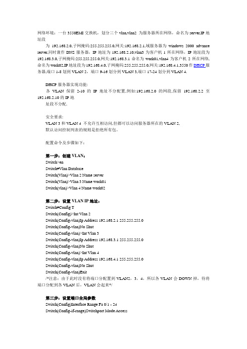
网络环境:一台3550EMI交换机,划分三个vlan,vlan2 为服务器所在网络,命名为server,IP地址段为192.168.2.0,子网掩码:255.255.255.0,网关:192.168.2.1,域服务器为windows 2000 advance server,同时兼作DNS服务器,IP地址为192.168.2.10,vlan3为客户机1所在网络,IP地址段为192.168.3.0,子网掩码:255.255.255.0,网关:192.168.3.1命名为work01,vlan4为客户机2所在网络,命名为work02,IP地址段为192.168.4.0,子网掩码:255.255.255.0,网关:192.168.4.1,3550作DHCP服务器,端口1-8划到VLAN 2,端口9-16划分到VLAN 3,端口17-24划分到VLAN 4.DHCP服务器实现功能:各VLAN保留2-10的IP地址不分配置,例如:192.168.2.0的网段,保留192.168.2.2至192.168.2.10的IP地址段不分配.安全要求:VLAN 3和VLAN 4 不允许互相访问,但都可以访问服务器所在的VLAN 2,默认访问控制列表的规则是拒绝所有包。
配置命令及步骤如下:第一步:创建VLAN:Switch>enSwitch#Vlan DatabaseSwitch(Vlan)>Vlan 2 Name serverSwitch(Vlan)>Vlan 3 Name work01Switch(vlan)>Vlan 4 Name work02第二步:设置VLAN IP地址:Switch#Config TSwitch(Config)>Int Vlan 2Switch(Config-vlan)Ip Address 192.168.2.1 255.255.255.0Switch(Config-vlan)No ShutSwitch(Config-vlan)>Int Vlan 3Switch(Config-vlan)Ip Address 192.168.3.1 255.255.255.0Switch(Config-vlan)No ShutSwitch(Config-vlan)>Int Vlan 4Switch(Config-vlan)Ip Address 192.168.4.1 255.255.255.0Switch(Config-vlan)No ShutSwitch(Config-vlan)Exit/*注意:由于此时没有将端口分配置到VLAN2,3,4,所以各VLAN会DOWN掉,待将端口分配到各VLAN后,VLAN会起来*/第三步:设置端口全局参数Switch(Config)Interface Range Fa 0/1 - 24Switch(Config-if-range)Switchport Mode AccessSwitch(Config-if-range)Spanning-tree Portfast第四步:将端口添加到VLAN2,3,4中/*将端口1-8添加到VLAN 2*/Switch(Config)Interface Range Fa 0/1 - 8Switch(Config-if-range)Switchport Access Vlan 2/*将端口9-16添加到VLAN 3*/Switch(Config)Interface Range Fa 0/9 - 16Switch(Config-if-range)Switchport Access Vlan 3/*将端口17-24添加到VLAN 4*/Switch(Config)Interface Range Fa 0/17 - 24Switch(Config-if-range)Switchport Access Vlan 4Switch(Config-if-range)Exit/*经过这一步后,各VLAN会起来*/第五步:配置3550作为DHCP服务器/*VLAN 2可用地址池和相应参数的配置,有几个VLAN要设几个地址池*/ Switch(Config)Ip Dhcp Pool Test01/*设置可分配的子网*/Switch(Config-pool)Network 192.168.2.0 255.255.255.0/*设置DNS服务器*/Switch(Config-pool)Dns-server 192.168.2.10/*设置该子网的网关*/Switch(Config-pool)Default-router 192.168.2.1/*配置VLAN 3所用的地址池和相应参数*/Switch(Config)Ip Dhcp Pool Test02Switch(Config-pool)Network 192.168.3.0 255.255.255.0Switch(Config-pool)Dns-server 192.168.2.10Switch(Config-pool)Default-router 192.168.3.1/*配置VLAN 4所用的地址池和相应参数*/Switch(Config)Ip Dhcp Pool Test03Switch(Config-pool)Network 192.168.4.0 255.255.255.0Switch(Config-pool)Dns-server 192.168.2.10Switch(Config-pool)Default-router 192.168.4.1第六步:设置DHCP保留不分配的地址Switch(Config)Ip Dhcp Excluded-address 192.168.2.2 192.168.2.10Switch(Config)Ip Dhcp Excluded-address 192.168.3.2 192.168.3.10Switch(Config)Ip Dhcp Excluded-address 192.168.4.2 192.168.4.10第七步:启用路由/*路由启用后,各VLAN间主机可互相访问*/Switch(Config)Ip Routing第八步:配置访问控制列表Switch(Config)access-list 103 permit ip 192.168.2.0 0.0.0.255 192.168.3.0 0.0.0.255Switch(Config)access-list 103 permit ip 192.168.3.0 0.0.0.255 192.168.2.0 0.0.0.255Switch(Config)access-list 103 permit udp any any eq bootpcSwitch(Config)access-list 103 permit udp any any eq tftpSwitch(Config)access-list 103 permit udp any eq bootpc anySwitch(Config)access-list 103 permit udp any eq tftp anySwitch(Config)access-list 104 permit ip 192.168.2.0 0.0.0.255 192.168.4.0 0.0.0.255Switch(Config)access-list 104 permit ip 192.168.4.0 0.0.0.255 192.168.2.0 0.0.0.255Switch(Config)access-list 104 permit udp any eq tftp anySwitch(Config)access-list 104 permit udp any eq bootpc anySwitch(Config)access-list 104 permit udp any eq bootpc anySwitch(Config)access-list 104 permit udp any eq tftp any第九步:应用访问控制列表/*将访问控制列表应用到VLAN 3和VLAN 4,VLAN 2不需要*/Switch(Config)Int Vlan 3Switch(Config-vlan)ip access-group 103 outSwitch(Config-vlan)Int Vlan 4Switch(Config-vlan)ip access-group 104 out第十步:结束并保存配置Switch(Config-vlan)End如何实现IP访问控制列表ACLs 的全称为访问控制列表(Access Control Lists)。
cisco 3560 交换机 所有Vlan之间互访

cisco 3560 交换机所有Vlan之间互访实验环境:Packet Tracer 5.3实验拓扑:实验配置:SW-2L1、创建VLAN,并将相应端口加入VLANSW-2L#vlan databaseSW-2L(vlan)#vlan 10SW-2L(vlan)#vlan 20SW-2L(vlan)#vlan 30SW-2L(config)#interface f0/1SW-2L(config-if)#switch access vlan 10SW-2L(config)#interface f0/2SW-2L(config-if)#switch access vlan 20SW-2L(config)#interface f0/3SW-2L(config-if)#switch access vlan 302、创建TRUNKSW-2L(config)#interface f0/24SW-2L(config-if)switch mode trunkSW-3L1、创建VLANSW-3L#vlan databaseSW-3L(vlan)#vlan 10SW-3L(vlan)#vlan 20SW-3L(vlan)#vlan302、创建TRUNKSW-3L(config)#interface f0/24Sw-3l(config)#switch mode accessSW-3L(config-if)#switch mode trunk3、开启三层交换路由功能SW-3L(conifg)#ip routing4、配置VLAN的IPSW-3L(config)#interface vlan 10SW-3L(config-if)#ip address 192.168.10.254 255.255.255.0 SW-3L(config-if)#no shutdownSW-3L(config)#interface vlan 20SW-3L(config-if)#ip address 192.168.20.254 255.255.255.0 SW-3L(config-if)#no shutdownSW-3L(conifg)#interface vlan30SW-3L(config-if)#ip address 192.168.30.254 255.255.255.0 SW-3L(config-if)#no shutdown5、配置三层交换路由接口SW-3L(config)#interface f0/23SW-3L(config-if)#no switchportSW-3L(config-if)#ip address 10.1.1.1 255.255.255.0SW-3L(config-if)#no shutdown6、配置RIP路由SW-3L(config)#router ripSW-3L(config-router)#no auto-summarySW-3L(config-router)#network 192.168.10.0SW-3L(config-router)#network 192.168.20.0SW-3L(config-router)#network 192.168.30.0SW-3L(conifg-router)#network 10.1.1.0。
怎样配置以cisco 3560的DHCP

怎样配置以cisco 3560的DHCP1.同时为多个VLAN的客户机分配地址2.VLAN内有部分地址采用手工分配的方式3.为客户指定网关、Wins服务器等4.VLAN 2的地址租用有效期限为1天,其它为3天5.按MAC地址为特定用户分配指定的IP地址最终配置如下:ip dhcp excluded-address 10.1.1.1 10.1.1.19 //不用于动态地址分配的地址ip dhcp excluded-address 10.1.1.240 10.1.1.254ip dhcp excluded-address 10.1.2.1 10.1.2.19!ip dhcp pool global //global是pool name,由用户指定network 10.1.0.0 255.255.0.0 //动态分配的地址段domain-name //为客户机配置域后缀dns-server 10.1.1.1 10.1.1.2 //为客户机配置dns服务器netbios-name-server 10.1.1.5 10.1.1.6 //为客户机配置wins服务器netbios-node-type h-node //为客户机配置节点模式(影响名称解释的顺利,如h-node=先通过wins服务器解释...)lease 3 //地址租用期限: 3天ip dhcp pool vlan1network 10.1.1.0 255.255.255.0 //本pool是global的子pool, 将从global pool继承domain-name等optiondefault-router 10.1.1.100 10.1.1.101 //为客户机配置默认网关!ip dhcp pool vlan2 //为另一VLAN配置的poolnetwork 10.1.2.0 255.255.255.0default-router 10.1.2.100 10.1.2.101lease 1!ip dhcp pool vlan1_john //总是为MAC地址为...的机器分配...地址host 10.1.1.21 255.255.255.0client-identifier 010050.bade.6384 //client-identifier=01加上客户机网卡地址!ip dhcp pool vlan1_tomhost 10.1.1.50 255.255.255.0client-identifier 010010.3ab1.eac8相关的DHCP调试命令:no service dhcp //停止DHCP服务[默认为启用DHCP服务]sh ip dhcp binding //显示地址分配情况show ip dhcp conflict //显示地址冲突情况debug ip dhcp server {events | packets | linkage} //观察DHCP服务器工作情况如果DHCP客户机分配不到IP地址,常见的原因有两个。
cisco 3560配置详解

目录CISCO Catalyst 3560-E系列交换机的功能应用及安全解决方案 (3)一、Cisco® Catalyst® 3560-E系列交换机介绍 (3)1、概述 (3)2、交换机配置 (3)3、Cisco Catalyst 3560-E软件 (5)4、万兆以太网上行链路和Cisco TwinGig SFP转换器 (5)5、模块化电源 (6)6、以太网供电 (6)7、冗余电源系统 (6)8、主要特性和优势 (6)9、可用性和可扩展性 (7)10、高性能IP路由 (7)11、出色的服务质量 (8)12、高级安全特性 (8)13、智能以太网供电(PoE)管理 (10)14、管理和控制特性 (10)15、网络管理工具 (11)二、Cisco® Catalyst® 3560-E系列交换机配置 (11)1、访问设备的方式 (11)2、查看CISCO 设备的简单运行状态 (11)3、Catalyst 3560接口说明 (11)4、Catalyst 3560接口配置 (11)5、交换机的启动及基本配置案例 (11)6、交换机的端口和MAC地址表的设置 (15)7、配置VLAN (15)7.1 vlan简介 (15)7.2 VLAN的的特性 (15)7.3 VLAN配置 (15)7.4 VLAN的删除 (16)7.5 将端口分配给一个VLAN (16)7.6 配置VLAN (17)7.7 配置VTP DOMAIN VTP DOMAIN 称为管理域。
(18)7.8 配置VLAN接口地址 (18)7.9、cisco 3560 pvlan 配置实例 (19)8、交换机HSRP配置 (20)9、路由协议配置 (21)9.1 RIP路由 (21)9.2 OSPF路由 (22)三、Cisco® Catalyst® 3560-E系列交换机安全防护 (23)1、思科交换机端口配置VLAN跟IP地址捆绑 (23)2、配置802.1X身份验证协议 (25)3、访问控制列表的应用 (26)案例一:VLAN1和VLAN2不能互访,但都可以和VLAN3互相访问 (26)案例二:要求所有VLAN都不能访问VLAN3 但VLAN3可以访问其他所有VLAN (26)案例三:用单向访问控制列表(reflect+evalute) (26)4、Cisco3560 交换机端口限速配置 (27)5. 交换机服务的安全策略 (29)6. 交换机端口安全----端口隔离 (30)CISCO Catalyst 3560-E系列交换机的功能应用及安全解决方案一、Cisco® Catalyst® 3560-E系列交换机介绍1、概述Cisco® Catalyst® 3560-E系列交换机(图1)是一个企业级独立式配线间交换机系列,支持安全融合应用的部署,并能根据网络和应用需求的发展,最大限度地保护投资。
在cisco3560G交换机配置ip,mac绑定

在cisco3560G交换机配置ip,mac绑定
在cisco的3560交换机上执行连接电脑的ip mac绑定,以加强网络安全
适用于没有dhcp的环境。
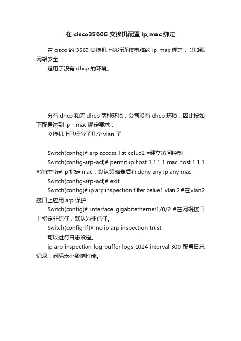
分有dhcp和无dhcp两种环境,公司没有dhcp环境,因此按如下配置达到ip - mac绑定要求:
交换机上已经分了几个vlan了
Switch(config)# arp access-list celue1 #建立访问控制
Switch(config-arp-acl)# permit ip host 1.1.1.1 mac host 1.1.1 #允许指定ip指定mac,默认策略最后有deny any ip any mac Switch(config-arp-acl)# exit
Switch(config)# ip arp inspection filter celue1 vlan 2 #在vlan2 接口上应用arp保护
Switch(config)# interface gigabitethernet1/0/2 #在网络接口上指定非信任,默认为非信任。
Switch(config-if)# no ip arp inspection trust
可以进行日志设定。
ip arp inspection log-buffer logs 1024 interval 300 配置日志记录,间隔太小影响性能。
思科模拟器:3560交换机实现DHCP功能

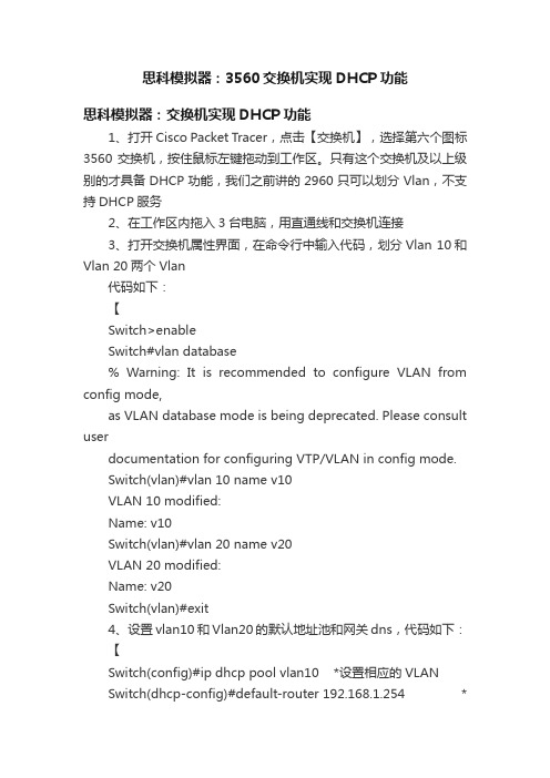
思科模拟器:3560交换机实现DHCP功能思科模拟器:交换机实现DHCP功能1、打开Cisco Packet Tracer,点击【交换机】,选择第六个图标3560交换机,按住鼠标左键拖动到工作区。
只有这个交换机及以上级别的才具备DHCP功能,我们之前讲的2960只可以划分Vlan,不支持DHCP服务2、在工作区内拖入3台电脑,用直通线和交换机连接3、打开交换机属性界面,在命令行中输入代码,划分Vlan 10和Vlan 20两个Vlan代码如下:【Switch>enableSwitch#vlan database% Warning: It is recommended to configure VLAN from config mode,as VLAN database mode is being deprecated. Please consult userdocumentation for configuring VTP/VLAN in config mode.Switch(vlan)#vlan 10 name v10VLAN 10 modified:Name: v10Switch(vlan)#vlan 20 name v20VLAN 20 modified:Name: v20Switch(vlan)#exit4、设置vlan10和Vlan20的默认地址池和网关dns,代码如下:【Switch(config)#ip dhcp pool vlan10 *设置相应的VLANSwitch(dhcp-config)#default-router 192.168.1.254 *设置该地址池的默认网关Switch(dhcp-config)#network 192.168.1.0 255.255.255.0 *设置分配的地址池Switch(dhcp-config)#dns-server 202.1.1.1 *设置该地址池的默认DNS地址。
思科3560的vlan acl典型配置

3560(config)#access-list 116 deny ip 172.1.1.0 0.0.0.255 any
3560(config)#access-list 116 deny ip 172.2.1.0 0.0.0.255 any
3560(config-if)#no sh
3560(config-if)#exit
3560(config)#interface vlan 171
3560(config-if)#ip add 172.1.1.1 255.255.255.0
3560(config-if)#no sh
3560(config-if)#exit
3560(config)#access-list 172 deny ip 172.7.1.0 0.0.0.255 any
3560(config)#access-list 172 deny ip 172.16.1.0 0.0.0.255 any
3560(config)#access-list 172 permit ip any any
3560(config-if-range)#switchport access vlan 177
3560(config-if-range)#ex
3560(config)#interface range f0/17 -20
3560(config-if-range)#switchport mode access
3560(config-if-range)#switchport access vlan 176
3560(config-if-range)#exit
Cisco 3560 VLAN的配置方法

如果动态分配IP地址,则设网络上的DHCP服务器IP地址为172.16.1.11。
(1)给VLAN所有的节点分配静态IP地址。
首先在核心交换机上分别设置各VLAN的接口IP地址。核心交换机将vlan做为一种接口对待,就象路由器上的一样,如下所示:
COM(config)#interface vlan 10
(2)给VLAN所有的节点分配动态IP地址。
首先在核心交换机上分别设置各VLAN的接口IP地址和同样的DHCP服务器的IP地址,如下所示:
COM(config)#interface vlan 10
COM(config-if)#ip address 172.16.58.1 255.255.255.0 VLAN10接口IP
在核心交换机端配置如下:
COM(config)#interface gigabitEthernet 2/1
COM(config-if)#switchport
COM(config-if)#switchport trunk encapsulation isl 配置中继协议
COM(config-if)#switchport mode trunk
PAR1(vlan)#vtp Client 设置交换机为客户端模式
PAR2#vlan database 进入VLAN配置模式
PAR2(vlan)#vtp domain COM 设置VTP管理域名称COM
PAR2(vlan)#vtp Client 设置交换机为客户端模式
PAR3#vlan database 进入VLAN配置模式
4、将交换机端口划入VLAN
例如,要将PAR1、PAR2、PAR3……分支交换机的端口1划入COUNTER VLAN,端口2划入MARKET VLAN,端口3划入MANAGING VLAN……
思科3560G交换机常用配置

思科3560G交换机常用配置一.配置telnet登陆账号和密码用串口线连上交换机Switch(config)#usernaSwitch(config)#username admin pasSwitch(config)#username admin password 123Switch(config)#line vty 0 4Switch(config-line)#login localSwitch(config-line)#end%SYS-5-CONFIG_I: Configured from console by consoleSwitch#wr二.配特权密码Switch#conf tEnter configuration commands, one per line. End with CNTL/Z.Switch(config)#enable password 456三.划分vlanSwitch(config)#vlan 10Switch(config-vlan)#int vlan 10Switch(config-if)#%LINK-5-CHANGED: Interface Vlan10, changed state to upSwitch(config-if)#ip add 192.168.10.1 255.255.255.0四.配dhcpSwitch(config)#ip dhcp pool vlan10Switch(dhcp-config)#network 192.168.10.0 255.255.255.0Switch(dhcp-config)#default-router 192.168.10.1Switch(dhcp-config)#dns-server 192.168.1.1Switch(dhcp-config)#五.划分端口Switch(config)#int range fastEthernet 0/1-5 进入1-5端口Switch(config-if-range)#switchport mode access 并把接口方式改为accessSwitch(config-if-range)#switchport access vlan 10把1-5端口划vlan 10Switch(config-if-range)#no sh六. 配静态路由Switch(config)#ip route 0.0.0.0 0.0.0.0 192.168.10.2 192.168.10.2是一跳地址七. 配置完一定要保存Switch#wrBuilding configuration...[OK]。
VLAN下使用Cisco3560配置DHCPRelay应用OSV智能桌面虚拟

VLAN下使用Cisco3560配置DHCPRelay应用OSV智能桌面虚拟VLAN 下使用 Cisco 3560 配置DHCP Relay 应用OSV 智能桌面虚拟化作者OSV在1 三月 2013, 10:04 上午Cisco 3560 配置DHCP Relay实例前言:在VLAN下使用DHCP Relay 进行OSV部署时,有一个必要条件,那就是所有的Vlan下都能和OSV 服务器进行网络通信,三层交换机的防火墙可调,二层+单臂路由时,路由器的防火墙可调。
举一个例子:Server IP :192.168.88.10 255.255.255.0Client IP :192.168.1.10 ?255.255.255.0在VLAN下这二个段可以通信吗?答应是肯定的,所有发往其他Vlan的数据,都会经过三层交换机,或者单臂路由进行转发,所以对单臂路由性能是有要求的。
Vlan 下进行OSV部署时,最好能有一台专用的DHCP服务器。
DHCP服务器每个IP池下添加066 和 067 这个组件,即可进行部署。
DHCP服务器可安装在OSV服务器上,推荐使用windows server 2008 r2 的服务器角色实验过程:网络环境:一台3560交换机,划分三个vlan,vlan2为服务器所在网络,命名为server,IP地址段为192.168.2.0,子网掩码:255.255.255.0,网关:192.168.2.1,域服务器为windows2000advanceserver,同时兼作DHCP服务器,DNS服务器,IP地址为192.168.2.10,vlan3为客户机1所在网络,IP地址段为192.168.3.0,子网掩码:255.255.255.0,网关:192.168.3.1命名为work01,vlan4为客户机2所在网络,命名为work02,IP地址段为192.168.4.0,子网掩码:255.255.255.0,网关:192.168.4.1.3560上端口1-8划到VLAN2,端口9-16划分到VLAN3,端口17-24划分到VLAN4.配置命令及步骤如下:第一步:创建VLAN:Switch>VlanDatabaseSwitch(Vlan)>Vlan2NameserverSwitch(Vlan)>Vlan3Namework01Switch(vlan)>Vlan4Namework02第二步:启用DHCP中继代理:/*关键一步,若缺少以下两条命令,在VLAN中使用“IPHELPER-ADDRESSDHCP服务器地址”指定DHCP服务器,客户机仍然不能获得IP地址*/Switch>EnableSwitch#ConfigtSwitch(Config)ServiceDhcpSwitch(Config)Ip Dhcp Relay Information Option? (cisco3550需要配置,其他不需要)第三步:设置VLANIP地址:Switch(Config)>IntVlan2Switch(Config-vlan)IpAddress192.168.2.1255.255.255.0Switch(Config-vlan)NoShutSwitch(Config-vlan)>IntVlan3Switch(Config-vlan)IpAddress192.168.3.1255.255.255.0Switch(Config-vlan)NoShutSwitch(Config-vlan)>IntVlan4Switch(Config-vlan)IpAddress192.168.4.1255.255.255.0Switch(Config-vlan)NoShutSwitch(Config-vlan)Exit/*注意:由于此时没有将端口分配置到VLAN2,3,4,所以各VLAN会DOWN掉,待将端口分配到各VLAN后,VLAN会起来*/ 第四步:设置端口全局参数Switch(Config)InterfaceRangeFa0/1-24Switch(Config-if-range)SwitchportModeAccessSwitch(Config-if-range)Spanning-treePortfast第五步:将端口添加到VLAN2,3,4中/*将端口1-8添加到VLAN2*/Switch(Config)InterfaceRangeFa0/1-8Switch(Config-if-range)SwitchportAccessVlan2/*将端口9-16添加到VLAN3*/Switch(Config)InterfaceRangeFa0/9-16Switch(Config-if-range)SwitchportAccessVlan3/*将端口17-24添加到VLAN4*/Switch(Config)InterfaceRangeFa0/17-24Switch(Config-if-range)SwitchportAccessVlan4Switch(Config-if-range)Exit/*经过这一步后,各VLAN会起来*/第六步:在VLAN3和4中设定DHCP服务器地址/*VLAN2中不须指定DHCP服务器地址*/Switch(Config)IntVlan3Switch(Config-vlan)IpHelper-address192.168.2.10Switch(Config)IntVlan4Switch(Config-vlan)IpHelper-address192.168.2.10第七步:启用路由/*路由启用后,各VLAN间主机可互相访问,若需进一步控制访问权限,则需应用到访问控制列表*/Switch(Config)IpRouting第八步:结束并保存配置Switch(Config-vlan)EndSwitch#CopyRunStart怎样配置以cisco 3560的DHCP1.同时为多个VLAN的客户机分配地址2.VLAN内有部分地址采用手工分配的方式3.为客户指定网关、Wins服务器等4.VLAN 2的地址租用有效期限为1天,其它为3天5.按MAC地址为特定用户分配指定的IP地址最终配置如下:ip dhcp excluded-address 10.1.1.1 10.1.1.19 //不用于动态地址分配的地址ip dhcp excluded-address 10.1.1.240 10.1.1.254 ip dhcp excluded-address 10.1.2.1 10.1.2.19!ip dhcp pool global //global是pool name,由用户指定network 10.1.0.0 255.255.0.0 //动态分配的地址段domain-name /doc/0d17022425.html //为客户机配置域后缀dns-server 10.1.1.1 10.1.1.2 //为客户机配置dns服务器netbios-name-server 10.1.1.5 10.1.1.6 //为客户机配置wins服务器netbios-node-type h-node //为客户机配置节点模式(影响名称解释的顺利,如h-node=先通过wins服务器解释…)lease 3 //地址租用期限: 3天ip dhcp pool vlan1network 10.1.1.0 255.255.255.0 //本pool是global的子pool, 将从global pool继承domain-name等optiondefault-router 10.1.1.100 10.1.1.101 //为客户机配置默认网关!ip dhcp pool vlan2 //为另一VLAN配置的poolnetwork 10.1.2.0 255.255.255.0default-router 10.1.2.100 10.1.2.101lease 1!ip dhcp pool vlan1_john //总是为MAC地址为…的机器分配…地址host 10.1.1.21 255.255.255.0client-identifier 010050.bade.6384 //client-identifier=01加上客户机网卡地址!ip dhcp pool vlan1_tomhost 10.1.1.50 255.255.255.0client-identifier 010010.3ab1.eac8相关的DHCP调试命令:no service dhcp //停止DHCP服务[默认为启用DHCP服务]sh ip dhcp binding //显示地址分配情况show ip dhcp conflict //显示地址冲突情况debug ip dhcp server {events | packets | linkage} //观察DHCP 服务器工作情况如果DHCP客户机分配不到IP地址,常见的原因有两个。
- 1、下载文档前请自行甄别文档内容的完整性,平台不提供额外的编辑、内容补充、找答案等附加服务。
- 2、"仅部分预览"的文档,不可在线预览部分如存在完整性等问题,可反馈申请退款(可完整预览的文档不适用该条件!)。
- 3、如文档侵犯您的权益,请联系客服反馈,我们会尽快为您处理(人工客服工作时间:9:00-18:30)。
VLAN 下使用 Cisco 3560 配置DHCP Relay 应用OSV 智能桌面虚拟化作者OSV在1 三月 2013, 10:04 上午Cisco 3560 配置DHCP Relay实例前言:在VLAN下使用DHCP Relay 进行OSV部署时,有一个必要条件,那就是所有的Vlan下都能和OSV 服务器进行网络通信,三层交换机的防火墙可调,二层+单臂路由时,路由器的防火墙可调。
举一个例子:Server IP :192.168.88.10 255.255.255.0Client IP :192.168.1.10 ?255.255.255.0在VLAN下这二个段可以通信吗?答应是肯定的,所有发往其他Vlan的数据,都会经过三层交换机,或者单臂路由进行转发,所以对单臂路由性能是有要求的。
Vlan 下进行OSV部署时,最好能有一台专用的DHCP服务器。
DHCP服务器每个IP池下添加066 和 067 这个组件,即可进行部署。
DHCP服务器可安装在OSV服务器上,推荐使用 windows server 2008 r2 的服务器角色实验过程:网络环境:一台3560交换机,划分三个vlan,vlan2为服务器所在网络,命名为server,IP地址段为192.168.2.0,子网掩码:255.255.255.0,网关:192.168.2.1,域服务器为windows2000advanceserver,同时兼作DHCP服务器,DNS服务器,IP地址为192.168.2.10,vlan3为客户机1所在网络,IP地址段为192.168.3.0,子网掩码:255.255.255.0,网关:192.168.3.1命名为work01,vlan4为客户机2所在网络,命名为work02,IP地址段为192.168.4.0,子网掩码:255.255.255.0,网关:192.168.4.1.3560上端口1-8划到VLAN2,端口9-16划分到VLAN3,端口17-24划分到VLAN4.配置命令及步骤如下:第一步:创建VLAN:Switch>VlanDatabaseSwitch(Vlan)>Vlan2NameserverSwitch(Vlan)>Vlan3Namework01Switch(vlan)>Vlan4Namework02第二步:启用DHCP中继代理:/*关键一步,若缺少以下两条命令,在VLAN中使用“IPHELPER-ADDRESSDHCP服务器地址”指定DHCP服务器,客户机仍然不能获得IP地址*/Switch>EnableSwitch#ConfigtSwitch(Config)ServiceDhcpSwitch(Config)Ip Dhcp Relay Information Option? (cisco3550需要配置,其他不需要)第三步:设置VLANIP地址:Switch(Config)>IntVlan2Switch(Config-vlan)IpAddress192.168.2.1255.255.255.0Switch(Config-vlan)NoShutSwitch(Config-vlan)>IntVlan3Switch(Config-vlan)IpAddress192.168.3.1255.255.255.0Switch(Config-vlan)NoShutSwitch(Config-vlan)>IntVlan4Switch(Config-vlan)IpAddress192.168.4.1255.255.255.0Switch(Config-vlan)NoShutSwitch(Config-vlan)Exit/*注意:由于此时没有将端口分配置到VLAN2,3,4,所以各VLAN会DOWN掉,待将端口分配到各VLAN后,VLAN会起来*/第四步:设置端口全局参数Switch(Config)InterfaceRangeFa0/1-24Switch(Config-if-range)SwitchportModeAccessSwitch(Config-if-range)Spanning-treePortfast第五步:将端口添加到VLAN2,3,4中/*将端口1-8添加到VLAN2*/Switch(Config)InterfaceRangeFa0/1-8Switch(Config-if-range)SwitchportAccessVlan2/*将端口9-16添加到VLAN3*/Switch(Config)InterfaceRangeFa0/9-16Switch(Config-if-range)SwitchportAccessVlan3/*将端口17-24添加到VLAN4*/Switch(Config)InterfaceRangeFa0/17-24Switch(Config-if-range)SwitchportAccessVlan4Switch(Config-if-range)Exit/*经过这一步后,各VLAN会起来*/第六步:在VLAN3和4中设定DHCP服务器地址/*VLAN2中不须指定DHCP服务器地址*/Switch(Config)IntVlan3Switch(Config-vlan)IpHelper-address192.168.2.10Switch(Config)IntVlan4Switch(Config-vlan)IpHelper-address192.168.2.10第七步:启用路由/*路由启用后,各VLAN间主机可互相访问,若需进一步控制访问权限,则需应用到访问控制列表*/Switch(Config)IpRouting第八步:结束并保存配置Switch(Config-vlan)EndSwitch#CopyRunStart怎样配置以cisco 3560的DHCP1.同时为多个VLAN的客户机分配地址2.VLAN内有部分地址采用手工分配的方式3.为客户指定网关、Wins服务器等4.VLAN 2的地址租用有效期限为1天,其它为3天5.按MAC地址为特定用户分配指定的IP地址最终配置如下:ip dhcp excluded-address 10.1.1.1 10.1.1.19 //不用于动态地址分配的地址ip dhcp excluded-address 10.1.1.240 10.1.1.254ip dhcp excluded-address 10.1.2.1 10.1.2.19!ip dhcp pool global //global是pool name,由用户指定network 10.1.0.0 255.255.0.0 //动态分配的地址段domain-name //为客户机配置域后缀dns-server 10.1.1.1 10.1.1.2 //为客户机配置dns服务器netbios-name-server 10.1.1.5 10.1.1.6 //为客户机配置wins服务器netbios-node-type h-node //为客户机配置节点模式(影响名称解释的顺利,如h-node=先通过wins服务器解释…)lease 3 //地址租用期限: 3天ip dhcp pool vlan1network 10.1.1.0 255.255.255.0 //本pool是global的子pool, 将从global pool继承domain-name等optiondefault-router 10.1.1.100 10.1.1.101 //为客户机配置默认网关!ip dhcp pool vlan2 //为另一VLAN配置的poolnetwork 10.1.2.0 255.255.255.0default-router 10.1.2.100 10.1.2.101lease 1!ip dhcp pool vlan1_john //总是为MAC地址为…的机器分配…地址host 10.1.1.21 255.255.255.0client-identifier 010050.bade.6384 //client-identifier=01加上客户机网卡地址!ip dhcp pool vlan1_tomhost 10.1.1.50 255.255.255.0client-identifier 010010.3ab1.eac8相关的DHCP调试命令:no service dhcp //停止DHCP服务[默认为启用DHCP服务]sh ip dhcp binding //显示地址分配情况show ip dhcp conflict //显示地址冲突情况debug ip dhcp server {events | packets | linkage} //观察DHCP服务器工作情况如果DHCP客户机分配不到IP地址,常见的原因有两个。
第一种情况是没有把连接客户机的端口设置为Portfast方式。
MS客户机开机后检查网卡连接正常,Link是UP的,就开始发送DHCPDISCOVER 请求,而此时交换机端口正在经历生成树计算,一般需要30-50秒才能进入转发状态。
MS客户机没有收到DHCP SERVER的响应就会给网卡设置一个169.169.X.X的IP地址。
解决的方法是把交换机端口设置为Portfast方式:CatOS(4000/5000/6000): set spantree portfast mod_num/port_num enable; IOS(2900/3500): interface … ; spanning-tree portfast。
另外一种情况是DHCP服务器和DHCP工作站不在同一个VLAN,这时候通常通过设置ip helper-address来解决:interface vlan1ip address 10.1.1.254 255.255.255.0 //假设DHCP服务器地址为10.1.1.8interface Vlan2ip address 10.1.2.254 255.255.255.0ip helper-address 10.1.1.8 //假设这是DHCP客户机所在的VLAN。
