MP04HBT490-24中文资料
HE-24W 24W 单组输出电源模块 技术参数说明说明书
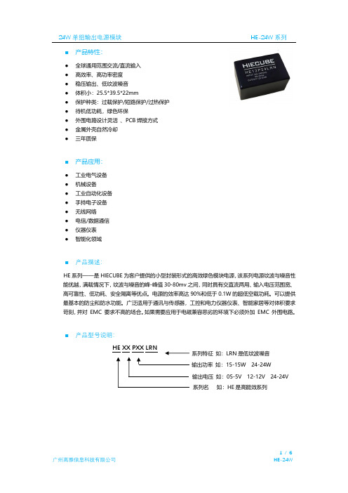
■ 产品特性:● 全球通用范围交流/直流输入 ● 高效率、高功率密度● 稳压输出、低纹波噪音 ● 体积小:25.5*39.5*22mm ● 保护种类:过载保护/短路保护/过热保护 ● 待机低功耗,绿色环保● 外围电路设计灵活 、PCB 焊接方式 ● 金属外壳自然冷却 ●三年质保■ 产品应用:● 工业电气设备 ● 机械设备 ● 工业自动化设备 ● 手持电子设备 ● 无线网络 ● 电信/数据通信 ● 仪器仪表●智能化领域■ 产品描述:HE 系列——是HIECUBE 为客户提供的小型封装形式的高效绿色模块电源,该系列电源纹波与噪音性能优越,满载情况下,纹波与噪音的峰-峰值30-80mv 之间,同时具有交直流两用、输入电压范围宽、 高可靠性、低功耗、安全隔离等优点。
电源的效率高达90%和低于0.1W 的超低空载功耗。
可以提供最基本的防尘和防水功能。
广泛适用于通讯与传感器,工控和电力仪器仪表、智能家居等对体积要求苛刻,并对 EMC 要求不高的场合。
如果需要应用于电磁兼容恶劣的环境下必须外加 EMC 外围电路。
■ 产品型号说明:HE XX PXX LRN系列名 如:HE 是高能效系列输出电压 如:05-5V 12-12V 24-24V 输出功率 如:15-15W 24-24W系列特征 如:LRN 是低纹波噪音■输入电气规格:■输出电气规格:■纹波与噪音特性:■通用特性:项目工作条件@测试结论开关频率65KHz短路保护可长期短路,自恢复过载保护>Load110%,可恢复过热保护模块表面温度在80℃(±4℃),进入过热保护耐压测试Input-Output 3000VAC /1min (耐压测试属于极限破坏实验,不可多次测试)工作温度-30~70℃(详细使用情况参考温度&降额曲线)存储温度-40~70℃模块重量47g(±2g)外壳尺寸25.5*39.5*22mm外壳材质铝外壳冷却方式自然冷却安全等级CLASS Ⅱ备注如未特别说明,所有规格参数均在输入电压为220VAC,环境温度25℃下测试。
IPC挠性印制电路用的挠性覆金属箔绝缘材料.

IPC-4204挠性印制电路用的挠性覆金属箔绝缘材料IPC-42042002.05内容目录1 范围...........................................1 3.4.2 胶粘剂.. (5)1.1 分类系统..................................1 3.4.3 覆金属 (5)1.1.1 非专用符号..............................1 3.4.4 片材 (5)1.1.2 专用符号..................................1 3.4.5 卷材.. (5)1.1.2.1 基膜类型................................1 3.5 外观要求.. (5)1.1.2.2 增强方式.................................1 3.5.1 标志 (5)1.1.2.3 增强类型..................................1 3.5.2 皱纹、折痕、条纹和划痕 (5)1.1.2.4 基膜厚度...................................1 3.5.3 杂夹物.. (6)1.1.2.5 胶粘剂类型................................1 3.5.4 空洞.. (6)1.1.2.6 胶粘剂厚度.................................2 3.5.5 孔洞、撕裂和分层.. (6)1.1.2.7 覆金属........................................2 3.6 尺寸要求 (6)1.1.2.7.1 规格单号...................................2 3.6.1 片材宽度和长度. (6)1.1.2.7.2 金属箔......................................2 3.6.2 卷材宽度. (6)1.1.2.7.3 金属箔类型................................2 3.6.3 卷材长度. (6)1.1.2.7.4 金属箔等级...............................2 3.6.4 绝缘厚度 (6)1.1.2.7.5 标称覆金属厚度..........................3 3.6.5 胶粘剂厚度 (6)1.1.2.7.6 粘结增强处理.............................3 3.6.6 金属箔厚度 (6)1.2 鉴定................................................3 3.7 物理性能要求 (7)1.3 质量一致性......................................3 3.7.1 尺寸稳定性.. (7)1.4 材料特性.........................................3 3.7.2 剥离强度.. (7)1.5 新材料............................................3 3.7.2.1 接收态剥离强度 (7)2 引用文件...........................................3 3.7.2.2 浮焊后剥离强度.. (7)2.1 IPC................................................4 3.7.2.3 温度循环后剥离强度.. (7)2.2 美国材料测试与材料协会(ASTM).....4 3.7.3 起始撕裂强度. (7)2.3 UL标准..........................................4 3.7.4 扩展撕裂强度. (7)2.4 NCSL国际标准................................4 3.7.5 弯曲疲劳. (7)2.5 ISO................................................4 3.7.6 低温可挠性. (7)3 要求................................................4 3.8 化学性能要求. (7)3.1 术语和定义.....................................4 3.8.1 耐化学性. (7)3.1.1 鉴定检验......................................4 3.8.2 耐浮焊性. (7)3.1.2 质量一致性检验.............................4 3.8.3 可焊性. (7)3.1.3 用户检验批..................................4 3.9 电性能要求.. (7)3.1.4 卖方检验批...................................4 3.9.1 介电常数. (7)3.1.5 结构相似的组成.............................4 3.9.2 介质损耗角正切. (7)3.1.6 空洞............................................5 3.9.3 体积电阻率(湿热). (7)3.1.7 杂夹物........................................5 3.9.4 表面电阻(湿热) (7)3.2 规格单...........................................5 3.9.5 介电强度 (7)3.3抵触..............................................5 3.10 环境性能要求 (7)3.4 材料..............................................5 3.10.1 耐霉性. (7)3.4.1 基膜...........................................5 3.10.2 吸水率 (8)3.10.3 阻燃性...................................8 4.9.4 参数能力评定 (11)3.10.4 使用温度................................8 4.9.5 参数分析 (11)3.10.5 耐湿性和绝缘电阻...................8 4.9.6质量一致性放宽检验.. (11)3.11 制造质量..................................8 4.9.6.1 放宽检验的条件. (11)4 质量保证条款................................8 4.9.6.2 放宽检验样本大小. (16)4.1 检验职责...................................8 4.9.6.3 检查控制计划的条件 (16)4.2 检验设备和检测设施...................8 5 交货准备 (16)4.3 标准实验室条件.........................8 5.1 包装. (16)4.4 容许偏差..................................8 6 说明 (16)4.5 检验分类..................................8 6.1 订单资料. (16)4.6 材料检验..................................8 6.2 特殊化学品暴露. (16)4.7 鉴定检验..................................8 6.3 参考 (16)4.7.1 特性检验………………………….8 图4.7.2 频度.....................................8 图4-1控制计划. (12)4.8 质量一致性检验........................8 图4-2 流程和控制/检验点图 (13)4.8.1 产品交货检验.........................9 图4-3 过程参数相关图. (14)4.8.2 样本单位...............................9 图4-4 质量一致性放宽检验图. (15)4.8.3 A组检验…………………………..9 表4.8.3.1 抽样方案.............................9 表1-1 基膜类型符号 (1)4.8.3.2 失效..................................10 表1-2 增强方式符号. (1)4.8.3.3 用户抽样方案......................10 表1-3 增强类型符号.. (2)4.8.3.4 拒收批...............................10 表1-4 基膜和胶粘剂厚度符号.. (2)4.8.4 B组检验...............................10 表1-5 胶粘剂类型符号.. (2)4.8.4.1 抽样方案............................10 表1-6 金属箔等级符号. (2)4.8.4.2失效..................................10 表1-7 铜箔厚度符号 (3)4.8.4.3 材料的不合格.....................10 表3-1 基膜标称厚度的允许偏差 (6)4.8.5 C组检验..............................10 表3-2 胶粘剂标称厚度的允许偏差. (6)4.8.5.1 抽样方案............................10 表4-1 试验方法频度. (9)4.8.5.2失效..................................10 表4-2 片材A组和B组检验抽样方案. (9)4.8.5.3 材料的不合格.....................10 表4-3 卷材A组和B组检验抽样方案. (9)4.9 统计过程控制(SPC) (10)4.9.1 参数标识 (11)4.9.2 参数诊断 (11)4.9.3 参数控制 (11)2002.05 IPC-4204挠性印制电路用的挠性覆金属箔绝缘材料1 范围本标准规定了用作挠性印制电路和挠性扁平电缆的挠性覆金属箔绝缘材料的分类系统、鉴定检验和质量一致性检验的要求。
宝钢汽车板标准基础培训
拉伸应变痕
牌号 B140H1,B180H1 B180H2 拉伸应变痕 3 个月 3 个月
Q/BQB 418双相高强度冷连轧钢板及钢带
牌号命名 X A
X X X/ X X X B
X C
A:B:宝钢 B:最小屈服强度值/最小抗拉强度 C:双相钢 (DP: Dual Phase) 例:B340/590DP
Q/BQB 419 低合金高强度冷连轧钢板及钢带
牌号命名方法
X A
XXX X B C
A:B:宝钢 B:最小屈服强度值 C:低合金(LA:low alloy) 例:B340LA
主要用途
牌 号 用 途 B340LA B410LA 结构件 结构件、加强件
电镀锌产品
牌号命名方法
X A
X+X B C
A:基板牌号 B:电镀锌代号E C:镀层种类代号 纯锌:Z 锌镍合金:ZN
+
X 5
4: D - 热镀锌的英文缩写
2: 屈服强度下限值 3: B:烘烤硬化 P:P强化 LA:低合金高强度 Y:IF钢 5:
{
Z: 纯锌 ZF:合金化
例: H220PD+ZF
表面结构
正常锌花 光整锌花 小锌花 光整小锌花 零锌花 锌铁合金 Z G X GX N R
表面处理
铬酸钝化 涂 油 L Y LY
通用标准举例
材料类型:金属 表面质量 顺序号 次种类:薄型钢
GMW2M-ST-S
CR3 HD70G70GU
冷轧产品 热镀锌 通用全球 种类:钢 钢产品成型等级 涂层标识
宝钢汽车板标准简介
2004年10月27日
概 况
可用于汽车板的标准结构: 基础部分:2个 冷轧低碳冲压用钢:3个 冷轧高强结构钢:5个 电镀锌产品:1个 热镀锌产品:1个
奥德维特说明书

PDA 系列产品的设计、制造、检查、试验及特性都应遵照适合的最新版IEC 和中国GB 标准及国际单位SI 制。
GB/T13730《地区电网数据采集与监控系统通用技术条件》GB/50171-92《电气装置安装工作盘、柜及二次回路接线施工及验收规范》DL/T630《交流采样远动终端通用技术条件》DL/478-92《静态继电保护及安全自动装置通用技术条件》GB/50062-92《电力装置的继电保护和自动装置设计规范》GB/T50063-2008《电力装置的电测量仪表装置设计规范》DL/T587-1996《微机继电保护装置运行管理规程》GB/T13729-2002《远动终端通用技术条件》GB/14285-93《继电保护和安全自动装置技术规程》GB/T17626.12-1998《振荡波抗扰度试验》GB/T17626.11-2008《电压暂降、短时中断和电压变化抗扰度试验》GB/T17626.10-1998《阻尼振荡磁场抗扰度试验》GB/T17626.8-2006《工频磁场的抗扰度试验》GB/T17626.6-2008《射频场感应的传导骚扰抗扰度》GB/T17626.5-2008《浪涌(冲击)抗扰度试验》GB/T17626.4-2008《电快速瞬变脉冲群抗扰度试验》GB/T17626.2-2006《静电放电抗扰度试验》GB/T 14047-1993《量度继电器和保护装置》GB 3836.3-2000《爆炸性气体环境用电气设备 第 3 部 分:增安型"e"》JB/T 10613-2006《数字式电动机综合保护装置》GB/T13850-1998《交流电量转换为模拟量或数字信号的电测量变送器》JJG596-1999《电子式电能表检定规程》GB/T17215.321-2008《静止式有功电能表(1级和2级)》GB/T 22264-2008《安装式数字显示电测量仪表》产品标准Contents 目 录A -01综合电力监控仪PDA-120系列B -13 三相智能型电力仪表 PDA-103系列C -31单相智能型电力仪表 PDA-101系列D -51 智能型电动机保护控制器 PDA-110MRK F -66参考设计图附录产品业绩G -73GB/T17215.322-2008《》静止式有功电能表(0.2S 级和0.5S 级)E -58 低压电动机保护装置 ADVP-1451产品简介功能详表产品特点PDA -120系列综合电力监控仪是北京奥德威特电力科技股份有限公司按IEC 国际标准开发,与当今国际先进技术同步的网络化综合电力监控仪表。
爱森莫尔电气 PKZM4 电动保护器说明书
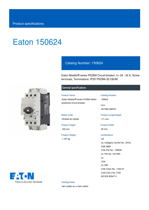
Eaton 150624Eaton Moeller® series PKZM4 Circuit-breaker, Ir= 24 - 32 A, Screw terminals, Terminations: IP2X PKZM4-32-CB/AKGeneral specificationsEaton Moeller® series PKZM4 Motor-protective circuit-breaker1506244015081468751PKZM4-32-CB/AK 171 mm 165 mm 55 mm 1.187 kgCEUL Category Control No.: DIVQ VDE 0660CSA File No.: 165628 UL File No.: E31593 UL CSA UL 489CSA Class No.: 1432-01 CSA-C22.2 No. 5-09 IEC/EN 60947-2Not usable as a main switchProduct NameCatalog Number EANModel Code Product Length/Depth Product Height Product Width Product Weight Certifications Catalog NotesTurn buttonComplete device with protection unitFor protection of cables and conductors Line and cable protectionThree-pole 30,000 operations (at 400V, AC-3)30,000 Operations (Main conducting paths)DIN rail (top hat rail) mounting optional40 Operations/hIII3Motor protective circuit breakerFinger and back-of-hand proof, Protection against direct contact when actuated from front (EN 50274)6000 V AC15 g, Mechanical, According to IEC/EN 60068-2-27, Half-sinusoidal shock 10 msFeeder and branch circuit as BCPD, (UL/CSA)DIN rail (top hat rail) mounting-5 - 40 °C to IEC/EN 60947, VDE 0660-25 - 55 °C, Operating range≤ 0.25 %/K, residual error for T > 40°Max. 2000 m -25 °C 1 x (0.75 - 16) mm², ferrule to DIN 462282 x (0.75 - 16) mm²14 - 8Actuator type Features Functions Number of poles Lifespan, electricalLifespan, mechanicalMounting MethodOperating frequencyOvervoltage categoryPollution degreeProduct categoryProtectionRated impulse withstand voltage (Uimp) Shock resistanceSuitable forTemperature compensationAltitudeAmbient operating temperature - minTerminal capacity (flexible with ferrule)Terminal capacity (flexible with ferrule AWG)55 °C25 °C40 °C40 °C80 °CDamp heat, constant, to IEC 60068-2-78 Damp heat, cyclic, to IEC 60068-2-301 x (0.75 - 16) mm²2 x (0.75 - 16) mm²14 - 614 mm3.3 Nm, Screw terminals, Main cable50 Hz60 Hz32 A600 V690 V32 A60 kA DC, up to 250 V DC, Main conducting paths65 kA, 480 Y/277 V, SCCR (UL/CSA)22 kA, 600 Y/347 V, SCCR (UL/CSA)Basic device fixed 15.5 x Iu, Trip Blocks496 A, Irm, Setting range max.± 20% tolerance, Trip blocks Screw terminalsAmbient operating temperature - maxAmbient operating temperature (enclosed) - min Ambient operating temperature (enclosed) - max Ambient storage temperature - minAmbient storage temperature - maxClimatic proofing Terminal capacity (solid)Terminal capacity (solid/stranded AWG) Stripping length (main cable) Tightening torqueRated frequency - minRated frequency - maxRated operational current (Ie)Rated operational voltage (Ue) - min Rated operational voltage (Ue) - max Rated uninterrupted current (Iu)Short-circuit currentShort-circuit current rating (UL 489 CSA 22.2-5.09) Short-circuit release ConnectionNumber of auxiliary contacts (change-over contacts) Number of auxiliary contacts (normally closed contacts) Number of auxiliary contacts (normally open contacts)0 A 32 A 18 W0 W6 W32 A0 WMeets the product standard's requirements.Meets the product standard's requirements.Meets the product standard's requirements.Meets the product standard's requirements.Meets the product standard's requirements.Does not apply, since the entire switchgear needs to be evaluated.Does not apply, since the entire switchgear needs to be evaluated.Meets the product standard's requirements.Does not apply, since the entire switchgear needs to be evaluated.Meets the product standard's requirements.Does not apply, since the entire switchgear needs to beOverload release current setting - min Overload release current setting - max Equipment heat dissipation, current-dependent PvidHeat dissipation capacity PdissHeat dissipation per pole, current-dependent PvidRated operational current for specified heat dissipation (In) Static heat dissipation, non-current-dependent Pvs10.2.2 Corrosion resistance10.2.3.1 Verification of thermal stability of enclosures10.2.3.2 Verification of resistance of insulating materials to normal heat10.2.3.3 Resist. of insul. mat. to abnormal heat/fire by internal elect. effects10.2.4 Resistance to ultra-violet (UV) radiation10.2.5 Lifting10.2.6 Mechanical impact10.2.7 Inscriptions10.3 Degree of protection of assemblies10.4 Clearances and creepage distances10.5 Protection against electric shockevaluated.Does not apply, since the entire switchgear needs to beevaluated.Is the panel builder's responsibility.Is the panel builder's responsibility.Is the panel builder's responsibility.Is the panel builder's responsibility.Is the panel builder's responsibility.The panel builder is responsible for the temperature rise calculation. Eaton will provide heat dissipation data for the devices.Is the panel builder's responsibility. The specifications for the switchgear must be observed.Is the panel builder's responsibility. The specifications for the switchgear must be observed.The device meets the requirements, provided the information in the instruction leaflet (IL) is observed.Save time and space thanks to the new link module PKZM0-XDM32ME Motor Starters in System xStart - brochureProduct Range Catalog Switching and protecting motorsSwitching and protecting motors - catalogeaton-manual-motor-starters-characteristic-pkzm4-characteristic-curve-002.epseaton-manual-motor-starters-pkzm4-characteristic-curve.epseaton-manual-motor-starters-characteristic-pkzm4-characteristic-curve.epseaton-manual-motor-starters-mounting-l-pkz0-indicator-light-dimensions.epseaton-manual-motor-starters-pkz-pkzm4-mccb-dimensions.epseaton-manual-motor-starters-pkzm4-mccb-3d-drawing.epsDA-CE-ETN.PKZM4-32-CB_AKeaton-motors-starters-pkzm4-motor-protective-circuit-breaker-instruction-leaflet-il03407012z.pdfIL03402025ZWIN-WIN with push-in technologyMN03402002Z_DE_ENpkzm4_16_cb_ak.dwgpkzm4_16_cb_ak.stpeaton-manual-motor-starters-transformer-pkzm0-wiring-diagram.eps10.6 Incorporation of switching devices and components10.7 Internal electrical circuits and connections10.8 Connections for external conductors10.9.2 Power-frequency electric strength10.9.3 Impulse withstand voltage10.9.4 Testing of enclosures made of insulating material 10.10 Temperature rise10.11 Short-circuit rating10.12 Electromagnetic compatibility10.13 Mechanical function BrochuresCatalogs Characteristic curve DrawingseCAD model Installation instructionsInstallation videos Manuals and user guides mCAD modelWiring diagramsEaton Corporation plc Eaton House30 Pembroke Road Dublin 4, Ireland © 2023 Eaton. All Rights Reserved. Eaton is a registered trademark.All other trademarks areproperty of their respectiveowners./socialmedia。
AMP04FSZ,AMP04FPZ,AMP04EPZ,AMP04FSZ-RL,AMP04FSZ-R7,AMP04FS-REEL7,AMP04ESZ-R7, 规格书,Datasheet 资料
One Technology Way, P.O. Box 9106, Norwood, MA 02062-9106, U.S.A.
Tel: 781/329-4700 World Wide Web Site:
Fax: 781/326-8703
© Analog Devices, Inc., 2000
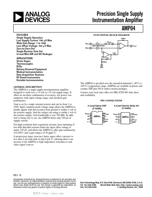
For high resolution data acquisition systems, laser trimming of low drift thin-film resistors limits the input offset voltage to under 150 µV, and allows the AMP04 to offer gain nonlinearity of 0.005% and a gain tempco of 30 ppm/°C.
1000 1 0.005 0.015 0.025 30
0.75 %
1.0 %
0.75
%
1000 V/V
%
%
%
50
ppm/°C
OUTPUT Output Voltage Swing High
Output Voltage Swing Low Output Current Limit
VOH
RL = 2 kΩ
Contact your local sales office for MIL-STD-883 data sheet and availability.
PIN CONNECTIONS
8-Lead Epoxy DIP (P Suffix)
8-Lead Narrow-Body SO (S Suffix)
25
技术及使用说明书

4.1 工作原理............................................................................................................................................... 5 4.2 保护逻辑............................................................................................................................................... 6 4.4 SOE 记录 ............................................................................................................................................... 7 4.5 硬件说明................................................................................................................................................ 7
3.1 工作环境条件 ........................................................................................................................................ 3 3.2 周围环境................................................................................................................................................ 3 3.3 电源 ....................................................................................................................................................... 3 3.4 主要技术参数 ........................................................................................................................................ 4
硬度指标钢的分类及性能

硬度名称符号单位解释布氏硬度HBMPa HBS(≤450)以钢球测得的硬度值;HBW(≤650)以硬质合金测得的硬度值。
洛氏硬度HRA 采用588.4N总负荷和金刚石压入器求得的硬度。
HRB 采用980.7N总负荷和压入直径1.59mm淬硬球的硬度HRC 采用1471.1N总负荷和金刚石压入器求得的硬度。
HRF 采用588.4总负荷和压入直径为1.588mm淬硬钢球求得的硬度,适用于薄软钢板、退火铜。
表面洛氏硬度(适用于表面经渗碳等表面处理的钢材)HR15N采用147.1N总负荷和金刚石压入器求得的硬度。
HR30N采用294.2N总负荷和金刚石压入器求得的硬度。
HR45N采用441.3N总负荷和金刚石压入器求得的硬度。
HR15T采用147.1N总负荷和压入直径为1.59mm淬硬钢球求得的硬度HR30T采用294.2N总负荷和压入直径为1.59mm淬硬钢球求得的硬度HR45T采用441.3N总负荷和压入直径为1.59mm淬硬钢球求得的硬度维氏硬度HV 以一定的负荷(目前最大的负荷是)吧136°方锥形金刚石压头压在材料表面,保持规定时间后卸除负荷,测量材料表面的压痕对角线平均长度,按公式用压痕面积来除与负荷所得的商。
钢的分类分类方法类别介绍按含碳量(1)低碳钢:含碳量低于0.25%(2)中碳钢:含碳量在0.25%-0.6%之间(3)高碳钢:含碳量超过0.6%按化学成分(1)非合金钢(2)低合金钢(3)合金钢按用途分(1)结构钢:主要用于制造各种工程结构和机器零件.(2)工具钢:主要用于制造各种工具量具和模具。
(3)特殊用途钢:如不锈钢、耐酸钢、耐热钢等。
按质量分(1)普通钢:含S量一般不超过0.055%,含P量不超过0.045%。
工装常用标准件手册HB1-4

快卸止动销HB1-704-83*长度L由设计确定,方法按L=L1+L2+B(B为夹层厚度),尾数取0、2、4、6、8。
技术条件HB1-708-83。
110扩口式直通管接头HB4-4-2002材料、热处理、表面处理及公称尺寸为10mm时的标记示例见表1。
表1111表1 单位为毫米112扩口式A型直通管接头HB4-5-2002材料、热处理、表面处理及公称尺寸为10mm时的标记示例见表1。
113表2单位为毫米114表2(续)单位为毫米115116扩口式B 型弯管接头 HB 4-10-2002表1 单位为毫米117表1(续)材料、热处理、表面处理及公称尺寸为10mm时的标记示例见表2。
118119扩口式C 型弯管接头 HB4-11-2002表1 单位为毫米120表1(续)单位为毫米材料、热处理、表面处理及公称尺寸为10mm时的标记示例见表2表2121122扩口式直角管接头 HB4-13-2002材料、热处理、表面处理及公称尺寸为10mm 时的标记示例见表1。
表1表2 单位为毫米123124扩口式B 型直角管接头HB 4-14-2002材料、热处理、表面处理及么称尺寸为10mm 时的标记示例见表1。
表1表2 单位为毫米125表2 (续)单位为毫米126127扩口式A 型直角管接头 HB 4-15-2002图1 第1尺寸系列结构图128注:未注尺寸按图1。
图2 第2尺寸系列结构单位为毫米129单位为毫米材料、热处理、表面处理及公称尺寸为10mm时的标记示例见表2。
表2130131扩口式三通管接头 HB4-17-2002材料、热处理、表面处理及公称尺寸为10mm 时的标记示例见表1。
表2 单位为毫米132133扩口式D 型三通管接头 HB4-18-2002D N >D N1时,接头的构型可从下述两种方案中任选材料、热处理、表面处理及公称尺寸为D N (d 0)=6mm 和D N1(d 01)=10mm 时的标记示例见表1表2 第1尺寸系列参数表单位为毫米单位为毫米134135136137138扩口式E 型三通管接头 HB 4-19-2002表1 单位为毫米材料、热处理、表面处理及公称尺寸为10mm时的标记示例见表2。
马来酸左旋氨氯地平治疗晨峰高血压的疗效观察

21 治疗前 后2 h . 4 的动 态血压 变化 (= 0 患者 服用药 物前 , 2小时平 n 6】 其 4 均收 缩压 和舒 张压分别 为(3. 士1 .) 183 08mmHg 9 . 68 和(02- .) 4 mmHg治 疗 , 后 , 4]时平均 收缩压和 舒 张压分 别为(2 .490mmHg (29 - . 其2 ̄ x 176 .) - 和 8 . 47 7, )降幅分 别为(o7 18mmHg (.409mmH 对结 果进行 c , t .4 .) -  ̄ 73 .) - g, 检验 其 差距 非常 明显 (<O叭 )具有 统计 学意 义 。 P . , 22 治疗前后血 压晨峰 的变化 患者服 用 . 前 后晨 峰血压 升高 程度 , 晨收 缩压 、 张压的变 化见表 l 清 舒 。
5 9 4
血压变 异和 减低晨峰 程度成 为降压 新 目 。 理想 的降压 药物 , 有 良好 f 的顺 应性 外 , 应能在 2h内平稳 降压 , 血压变异 性 , 4 降低 降低患者 清晨血 压 , 使高 血压 患 者安 全度过心 脑血 管事件 高 发时段 , 保护 靶器 官功 能 。 有效 大 量 文献报 道 以下措施 可以很好 控制血 压晨峰 现象 : ) 药物 定时 释放 ( 使用 1 制 剂C R( nr !xedrlae, 类制 剂 品种很 少且价 格 昂贵 。 ) OE c to etn e s)但这 o e ( 2 使 用作用 较 强且持 续时 间较长 又平稳 的 降压药 物 , 米 沙坦 、 氯地 平 如替 氨
律 失常 的临床疗 效要 比利 多卡 因更加 显著 , 值得 临床 推广 应用 。
【1 李星阳. 1 胺碘酮与利多卡因治疗心肺复苏术过程中室性心律失常效果 对 比【】 中外医疗 ,00(8 J. 21, ) 0 【】 李强. 2 可达龙利多卡因治疗室性心动过速临床疗效观察【】基层医学 J。
宝钢热轧板的牌号及其标准
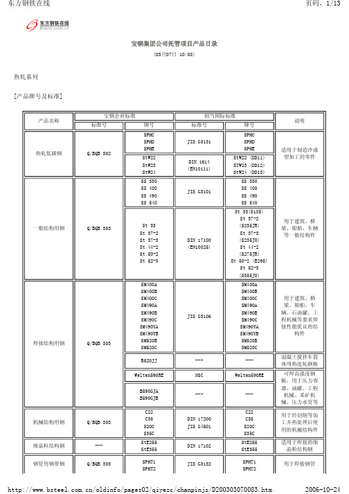
Q/BQB 303
St 33 St 37-2 St 37-3 St 44-2 St 50-2 St 52-3
Q/BQB 303
Q/BQB 303 ---
Q/BQB 303
SM400A SM400B SM400C SM490A SM490B SM490C SM490YA SM490YB SM520B SM520C
/oldinfo/pages02/qiyezc/chanpinjs/D200303070083.htm
2006-10-24
东方钢铁在线
页码,4/13
冷轧
Q/BQB 409-1999
Q/BQB 418-1999
深冲用超低碳含P冷连轧钢带
深冲用烘烤硬化钢 一般加工用含P高强度冷连轧钢
340)
B180H2 (180~280,≥
340)
JSC340H (185~285,≥
340)
JSC340H (185~285,≥
340)
SPFC340H (≥185;≥340)
B210H2
(210~320,≥
NK Super UFD
(实例: s=145, b =280)
GM CQ/St12/Grade 1
(≥140) DQ/St13/Grade 2 (140~260,≥270)
DQSK/St14/Grade 3 (140~205,≥270)
DDQ/St15/Grade 4 (140~185,≥270)
EDDQ/Fep06/Grade 5 (140~170,≥270)
---
用于要求成形性 加工性能的汽车 构架、车轮等汽
车结构件
冷变形用热轧粒 钢,用于要求良 好冷成型性能并 有较高或高强度 要求的汽车大梁
粉末冶金材料标准表

公司制造的铁基粉末冶金零件执行标准与成分性能<一>G B/59066< 690 35 60烧结铁和烧结碳钢的化学成分(%).材料牌号Fe CF-0000注: 用差减法求出的其它元素(包括为了特殊目的而添加的其它元素)总量的最大值为%。
▲注: 用差减法求出的其它元素(包括为了特殊目的而添加的其它元素)总量的最大值烧结铁-铜合金和烧结铜钢的化学成分(%).材料牌号 Fe Cu CFC-0200烧结铁-镍合金和烧结镍钢的化学成分(%).材料牌号Fe Ni Cu CFN-0200注: 用差减法求出的其它元素(包括为了特殊目的而添加的其它元素)总量的最大值为%⊙ 铁-铜合金和铜钢粉末冶金材料性能(MPIF-35)材料编号最小强度(A)(E)拉伸性能横向断裂压缩屈服强度%)硬度密度屈服极限极限强度屈服强度%)伸长率宏观(表现)微观(换算的)MPa MPa MPa % MPa MPa 络氏g/cm3FC-0200-15-18-21-24 100 170 140 310 12011HRBN/A 120 190 160 350140 18140 210 180 390 160 26170 230 200 430 180 36FC-0205-30-35-40-45 210 240 240 < 410 34037HRBN/A 240 280 280 < 520 370 48280 340 310 < 660 390 60310 410 340 < 790 410 72FC-0205-60HT-70HT-80HT-90HT 410 480 < 660 39019HRC58HRC 480 550< 760 490 25 58 550620 (D) < 830 590 31 58 620 690 < 930 660 36 58FC-0208-30-40 210 240 240 < 410 39050HRBN/A<三>"DIN V 30 910" 及"ISO5755" (成分与性能略)< 规格二- 不锈钢>FTG60-25(50R) 材料的物理性能FTG60-25(50R) 材料的力学性能。
红蓝双色贴片式发光二极管产品名称:0404-T0.4 XL-1010SURUBC 型号:XL-101

产品承认书产品名称:0404-T0.4红蓝双色贴片式发光二极管产品型号:XL-1010SURUBC客户名称:客户料号:承认日期:深圳市成兴光电子科技有限公司制定审核核准客户承认栏确认审核核准一、产品描述:●外观尺寸(L/W/H): 1.0x1.0x0.4mm●颜色:红蓝双色●胶体:透明胶体●EIA规范标准包装●环保产品,符合ROHS要求●适用于自动贴片机●适用于红外线回流焊制程二、外形尺寸及建议焊盘尺寸:备注:1.2.单位公差:毫米(mm):如无特别标注则为±0.10mm三、建议焊接温度曲线:有铅制程无铅制程四、最大绝对额定值(Ta=25℃):参数符号最大额定值单位消耗功率Pd 红55mW 蓝80最大脉冲电流(1/10占空比,0.1ms脉宽)I FP红100mA蓝100正向直流工作电流I F 红25mA 蓝25反向电压V R 红5V 蓝5工作环境温度Topr-30°C~+85°C 存储环境温度Tstg-40°C~+90°C焊接条件Tsol 回流焊:260°C,10s 手动焊:300°C,3s抗静电能力ESD2000V五、光电参数(Ta=25℃):参数符号颜色最小值代表值最大值单位测试条件光强IV 红42/59mcd IF=20mA 蓝40/68半光强视角2θ1/2//120/deg IF=20mA主波长λD 红619/624nm IF=20mA 蓝463/472正向电压VF 红 1.9/ 2.1V IF=20mA 蓝 2.6/ 3.2反向电流IR 红//1uA VR=5V 蓝//1备注:1.发光强度是由光纤和过滤器的组合测定的,因此接近视觉感应曲线;2.半光强视角是轴向发光强度一半时的离轴角;3.主波长λd源自CIE色度图,代表单一的波长,它定义了器件的颜色。
亮度分档:电压分档:波长分档:颜色代码最小值最大值单位测试条件红L224259mcd IF =20mA 蓝L324052mcdIF =20mAL335268颜色代码最小值最大值单位测试条件红F3 1.9 2.1VIF =20mA蓝I5 2.6 2.8VIF =20mAI6 2.8 3.0I73.03.2颜色代码最小值最大值单位测试条件红R22619624nm IF =20mA 蓝B11463466nmIF =20mAB12466469B13469472六、光电参数代表值特征曲线:φ60七、标签标识:CAT:光强(mcd)HUE:波长(nm)REF:电压(V)误差范围a.Luminous Intensity:±15%b.HUE:±1nmc.Forward Voltage:±0.1V八、包装载带与圆盘尺寸:φ13.0备注:1.尺寸单位为毫米(mm);2.尺寸公差如无标注,为±0.15mm;九、圆盘及载带卷出方向及空穴规格:尾端空壳载带的组合开始端空壳载带的组合盖带与空壳载带的组合十、内包装及外包装:内标签圆盘干燥剂防潮防静电袋5cartons/box外标签抽真空、热封10bags/carton至少160mm盖带和装有零件部分至少160mm盖带和至少160mm独立盖带或十一、信赖性实验:测试项目测试条件测试次数参考标准失效判定标准失效LED 数量(PCS )防潮等级1.回流焊最高温度=260℃,10秒,2次回流焊;2.回流焊之前存储条件:30℃,相对湿度=70%,168H;-JEITAED-4701300.301﹟10/22焊接信赖性(无铅回流焊)回流焊最高温度=245±5℃,5秒(无铅回流焊)-JEITAED-4701303303A ﹟20/22冷热循环-40℃30分钟~25℃5分钟~100℃30分钟~25℃5分钟300个循环JESD22-A104﹟10/22冷热冲击-35℃15分钟转换时间3分钟85℃15分钟300个循环JESD22-A106﹟10/22高温存储Ta=100℃1000小时JESD22-A103﹟10/22低温存储Ta=-40℃1000小时JESD22-A119﹟10/22常温老化Ta=25℃IF=20mA1000小时JESD22-A108﹟10/22(2)失效标准★U.S.L :规格上限L.S.L :规格下限标准﹟项目测试条件失效标准﹟1正向电压(V F )I F =20mA >U.S.L*1.1光强(IV )I F =20mA <L.S.L*0.7反向电流(I R )V R =5V >U.S.L*2.0﹟2焊接可靠性/锡膏覆盖焊盘比例小于95%十二、使用注意事项:◆使用:1.过高的温度会影响LED的亮度以及其他性能,所以为使LED有较好的性能表现,应将LED远离热源。
4D24柴油机培训教材

4、活塞喷油冷却,机体带有喷嘴专用的内油道,喷油压力 均匀,冷却效果好。
5、机油散热器安装在机体上,由机体冷却液直接冷却,散 热效果好,管路简单可靠。
6、进、排气同侧安装发动机右侧,结构紧凑,适宜整车布 置。
7、喷油泵安装在发动机左侧(发动机前端看)。
8、干式薄壁汽缸套,增强机体刚性,可靠性高。
9、2.8kW减速启动马达,尺寸小,功率大,转速高,启动 可靠性好。
4D24柴油机产品介绍与维修保养 培训教材
北京福田环保动力股份有限公司编制 2006年8月
目录
前言
退出
奥铃4D24(BJ486ZQ)增压柴油机是经美国西南研究院技术咨询,由我公司 完全自主全新开发的满足欧II排放法规的轻型汽车柴油机机型,具有动力性
前页 后页
高,冷起动性能好,适用范围广、燃油经济性好、噪音低、结构紧凑、配合
≤110
净质量(kg)
215
外形尺寸(长x宽x高)
754×592×632
排放
排放满足GB18352.2-2001法规(欧Ⅱ)要求
2、4D24柴油机主要结构特点
目录 退出
1、4D24柴油机采用龙门式缸体,结构刚性好,振动噪声低。前页
2、采用偏心曲柄连杆机构,运转平稳,机械噪声低。 后页
3、正时采用4齿轮传动,是发动机中正时齿轮最少的机型, 传动平稳啮合噪声低,材质采用42CrMo优质合金钢,耐磨性 更好,寿命更长。
3、4D24增压柴油机的技术优势分析
4、4D24增压柴油机使用及维护
5、4D24柴油机维护主要技术数据
6、4D24柴油机故障诊断与排除
一、4D24增压柴油机产品介绍
目录 退出
前页
4D24(BJ486ZQ)柴油机是经美国西南研究院技术咨询,后页 我公司自主全新研发完全满足欧II排放法规的轻型汽车柴油 机。通过增大排量的和机体结构优化设计,整机动力性和可 靠性显著提高;供油和燃烧系统采用AVL最新技术,燃油消耗 降低10%,冷起动性能大幅度提高;闭环电控EGR的采用和燃 烧的优化组织,使排放进一步降低;4D24(BJ486ZQ)柴油机 具有低油耗、低排放、低噪音、高动力性的特点,可满足轻 客、皮卡、载货卡车的柴油动力需要。
参数用量选择

管螺纹知识常见的管螺纹主要包括以下几种:1)NPT管螺纹,属于美国标准的60度椎管螺纹,用于北美地区,国标查阅GB/T12716-1991。
⌝2)PT管螺纹,是55度密封圆椎管螺纹,多用于欧洲及英联邦国家,常用于水及煤气管行业,锥度1:16,国标查阅GB/T7306-2000,国内叫法为ZG.。
⌝3)G是55度非螺纹密封管螺纹,标记为G代表圆柱螺纹。
国标查阅GB/T7307-2001。
⌝另外螺纹中的1/4、1/2、1/8 标记是指螺纹尺寸的直径,单位是英寸.行内人通常用分来称呼螺纹尺寸,一等于8分,1/4就是2分,如此类推.G 就是管螺纹的统称(Guan),55、60度的划分属于功能性的。
ZG俗称管锥,即螺纹由一圆锥面加工而成。
国标标注为Rc公制螺纹用螺距来表示,美英制螺纹用每英寸内的螺纹牙数来表示,这是它们最大的区别,公制螺纹是60度等边牙型,英制螺纹是等腰55度牙型,美制螺纹60度。
公制螺纹用公制单位,美英制螺纹用英制单位。
管螺纹主要用来进行管道的连接,其内外螺纹的配合紧密,有直管与锥管两种。
公称直径是指所连接的管道直径,显然螺纹直径比公称直径大。
1/4,1/2,1/8是英制螺纹的公称直径,单位是英寸。
ISO标准内的英制管螺纹已转化为米制单位制.英制管螺纹的米制化方法非常简单,将原来管螺纹的英寸尺寸乘以25.4就转化为毫米尺寸.碳素结构钢的力学性能(GB700-88)注:A、B、C为质量等级,D级为优质级。
椭球加工宏程序%1000#1=100;球半径#2=10;球头刀半径#3=10;预留加工余量#4=0; 初始角度#5=90;终止角度#6=1;角度增量G92 X0 Y0 Z150#10=#1+#2+#3#11=#10*COS[#4*PI/180]#13=#10*SIN[#4*PI/180]G90 G17 G00 X[#11+10] Y0 Z150 M03 S500 Z[#13+15]G01 Z[#13] F100G01 X[#11] Y0 F200G02 I[-#11]#0=#4+#6WHILE #0 LE #5#11=#10*COS[#0*PI/180]#13=#10*SIN[#0*PI/180]G18 G02 X[#11] Y0 Z[#13] I[-#11] K[-#13] G17 G02 I[-#11]#0=#0+#6ENDWG90 G00 Z150 M05X0 Y0M30刀具补偿功能在编写加工程序时,一般是按照零件轮廓来决定零件基(节)点在程序中的坐标尺寸。
(产品管理)黄铜产品问

(产品管理)黄铜产品问Q:日本标准中表示黄铜棒的状态有几种,分别用什么字母表示代表什么意思?A:四种;分别是“F”、“O”、“”1/2H、“H”;“F”表示制造状态;“O”表示软态;“1/2H”表示半硬态;“H”表示硬态。
1、Q:日本标准中牌号后面的“BD”、“BE”、“BF”分别表示什么意思?A:“BF”表示铸造棒料;“BE”表示挤制棒料;“BD”表示拉制棒料。
例如:C3604BD表示牌号为C3604的拉制铜棒。
2、Q:日本标准中牌号后面的“BD”后面跟字母“S”表示什么意思?A:“S”表示自动车床加工。
例如:C3604BDS表示牌号为C3604的拉制铜棒用于自动车床加工。
3、Q:日本标准中对用于导电材料牌号后面的“BD”后面跟字母“C”表示什么意思?A:“C”仅表示是导电用材料。
4、Q:日本标准棒材的完整表示方式是怎么的,且说明其具体含义?A:“C3604BDS-1/2H”表示牌号为C3604用于自动车床加工、半硬态的拉制棒;“C1100BDC-1/2H”表示牌号为C1100导电用的、半硬态的拉制棒。
5、Q:日本标准线材的完整表示方式是怎么的,且说明其具体含义?A:“C3604W-1/2H”表示牌号为C3604半硬态的线材。
6、Q:日本标准号“JISH3250-2000”和“JISH3260-2000”分别是什么意思?A:“JISH3250-2000”表示铜及铜合金棒的执行标准;“JISH3260-2000”表示铜及铜合金线的执行标准。
7、Q:日本标准“JISH3250-2000”和“JISH3260-2000”中铅黄铜各有哪些牌号?A:“JISH3250-2000”包含以下牌号:C3601、C3602、C3603、C3604、C3605、C3712、C3771七个牌号合金;“JISH3260-2000”包含以下牌号:C3501、C3601、C3602、C3603、C3604五个牌号合金。
从此也能够见出日本标准没有C3501的棒材及没有C3605、C3712、C3771的线材。
电路板常用材料及参数介绍(精)

电路板常用材料及参数介绍PCB电路板板材介绍:按品牌质量级别从底到高划分如下:94HB-94VO-22F-CEM-1-CEM-3-FR-4详细参数及用途如下:94HB:普通纸板,不防火(最低档的材料,模冲孔,不能做电源板)94V0:阻燃纸板(模冲孔)22F:单面半玻纤板(模冲孔)CEM-1:单面玻纤板(必须要电脑钻孔,不能模冲)CEM-3:双面半玻纤板(除双面纸板外属于双面板最低端的材料,简单的双面板可以用这种料,比FR-4会便宜5~10元/平米)FR-4: 双面玻纤板阻燃特性的等级划分可以分为94VO-V-1 -V-2 -94HB 四种半固化片:1080=0.0712mm,2116=0.1143mm,7628=0.1778mmFR4 CEM-3都是表示板材的,fr4是玻璃纤维板,cem3是复合基板无卤素指的是不含有卤素(氟溴碘等元素)的基材,因为溴在燃烧时会产生有毒的气体,环保要求。
Tg是玻璃转化温度,即熔点。
电路板必须耐燃,在一定温度下不能燃烧,只能软化。
这时的温度点就叫做玻璃态转化温度(Tg点),这个值关系到PCB板的尺寸耐久性。
什么是高Tg PCB线路板及使用高Tg PCB的优点高Tg印制电路板当温度升高到某一阀值时基板就会由"玻璃态”转变为“橡胶态”,此时的温度称为该板的玻璃化温度(Tg)。
也就是说,Tg是基材保持刚性的最高温度(℃)。
也就是说普通PCB基板材料在高温下,不断产生软化、变形、熔融等现象,同时还表现在机械、电气特性的急剧下降,这样子就影响到产品的使用寿命了,一般Tg的板材为130℃以上,高Tg一般大于170℃,中等Tg约大于150℃;通常Tg≥170℃的PCB印制板,称作高Tg印制板;基板的Tg提高了,印制板的耐热性、耐潮湿性、耐化学性、耐稳定性等特征都会提高和改善。
TG 值越高,板材的耐温度性能越好,尤其在无铅制程中,高Tg应用比较多;高Tg 指的是高耐热性。
- 1、下载文档前请自行甄别文档内容的完整性,平台不提供额外的编辑、内容补充、找答案等附加服务。
- 2、"仅部分预览"的文档,不可在线预览部分如存在完整性等问题,可反馈申请退款(可完整预览的文档不适用该条件!)。
- 3、如文档侵犯您的权益,请联系客服反馈,我们会尽快为您处理(人工客服工作时间:9:00-18:30)。
FEATURESs Dual Device Module s Electrically Isolated Package s Pressure Contact Construction s International Standard Footprint s Alumina (Non Toxic) Isolation Medium sIntegral Water Cooled HeatsinkAPPLICATIONSs Motor Controls Controlled Rectifier Bridges s Heater Control sAC Phase ControlVOLTAGE RATINGSORDERING INFORMATIONOrder As:MP04HBT490-28 or MP04HBT490-26 or MP04HBT490-24MP04HBP490-28 or MP04HBP490-26 or MP04HBP490-24MP04HBN490-28 or MP04HBN490-26 or MP04HBN490-24Note: When ordering, please use the whole part number.KEY PARAMETERS V DRM 2800V I T(AV)490A I TSM(per arm)11250A V isol3000VAdvance InformationReplaces Jun3 2000 version, DS5204-1.2DS5204-2.1 April 2001Fig. 2 Electrical connections - (not to scale)280026002400MP04---490-28MP04---490-26MP04---490-24ConditionsT vj = 0˚ to 125˚C,I DRM = I RRM = 50mA V DSM = V RSM =V DRM = V RRM + 100V respectivelyLower voltage grades available.Type NumberRepetitive PeakVoltages V DRM V RRMV Fig.1 Circuit diagramsModule type code: MP04.For further information see Package Details.Test ConditionsHalf wave resistive loadT case = 75˚C T case = 85˚CT case = 75˚C10ms half sine, T j = 125˚CV R = 010ms half sine, T j = 125˚CV R = 50% V DRMCommoned terminals to base plate.AC RMS, 1 min, 50HzSymbol I T(AV)I T(RMS I TSM I 2t I TSM I 2t V isolUnits A A A kA A 2s kA A 2s VMax.49042077011.25633 x 1039506 x 1033000Test Conditionsdc, 4.5 Ltr/min Half wave, 4.5 Ltr/min 3 Phase, 4.5 Ltr/minMounting torque = 5Nm with mounting compound Reverse (blocking)-Mounting - M6Electrical connections - M10-ParameterThermal resistance - junction to water (per thyristor or diode)Thermal resistance - case to heatsink (per thyristor or diode)Virtual junction temperature Storage temperature range Screw torqueWeight (nominal)THERMAL AND MECHANICAL RATINGSABSOLUTE MAXIMUM RATINGS - PER ARMStresses above those listed under 'Absolute Maximum Ratings' may cause permanent damage to the device. In extreme conditions, as with all semiconductors, this may include potentially hazardous rupture of the package. Appropriate safety precautions should always be followed. Exposure to Absolute Maximum Ratings may affect device reliability.ParameterMean on-state currentRMS valueSurge (non-repetitive) on-current I 2t for fusingSurge (non-repetitive) on-current I 2t for fusing Isolation voltageSymbol R th(j-c)R th(c-hs)T vj T stg --Units ˚C/kW ˚C/kW ˚C/kW ˚C/kW˚C ˚CNm (lb.ins)Nm (lb.ins)gMax.0.0560.0600.0660.021251306 (35)12 (106)1580Min.-----–40---Units mA V/µs A/µsV m ΩTest ConditionsAt V RRM /V DRM , T j = 125˚C To 67% V DRM , T j = 125˚CFrom 67% V DRM to 1500A, gate source 1.5A,t r = 0.5µs, T j = 125˚CAt T vj = 125˚C. See note 1At T vj = 125˚C. See note 1ParameterPeak reverse and off-state current Linear rate of rise of off-state voltage Rate of rise of on-state currentThreshold voltage On-state slope resistanceDYNAMIC CHARACTERISTICS - THYRISTORSymbol I RRM /I DRM dV/dt dI/dtV T(TO)r TMax.5010005000.910.65Min.-----ParameterGate trigger voltage Gate trigger current Gate non-trigger voltage Peak forward gate voltage Peak forward gate voltage Peak reverse gate voltage Peak forward gate current Peak gate power Mean gate powerTest ConditionsV DRM = 5V, T case = 25o C V DRM = 5V, T case = 25o C At V DRM T case = 125o CAnode positive with respect to cathode Anode negative with respect to cathode-Anode positive with respect to cathode See table fig. 5-Symbol V GT I GT V GD V FGM V FGN V RGM I FGM P GM P G(AV)GATE TRIGGER CHARACTERISTICS AND RATINGSMax.3.52000.25300.2551015010Units V mA V V V V A W WNote 1: The data given in this datasheet with regard to forward voltage drop is for calculation of the power dissipation in the semiconductor elements only. Forward voltage drops measured at the power terminals of the module will be in excess of these figures due to the impedance of the busbar from the terminal to the semiconductor.(with 50% V RSM at T case = 125˚C)specified conduction angles, sine wave 50/60Hzspecified conduction angles, square wave 50/60Hzstate current at specified conduction angles,sine wave 50/60Hzstate current at specified conduction angles,square wave 50/60Hzpower loss and maximum permissible case temperaturepower loss and maximum permissible case temperaturePACKAGE DETAILSFor further package information, please visit our website or contact your nearest Customer Service Centre. All dimensions in mm, unless stated otherwise. DO NOT SCALE.POWER ASSEMBLY CAPABILITYThe Power Assembly group provides support for thosecustomers requiring more than the basic semiconductor ing CAD design tools the group has developed a flexible range of heatsink / clamping systems in line with advances in device types and the voltage and current capability of Dynex semiconductors.An extensive range of air and liquid cooled assemblies is available covering the range of circuit designs in general use today.HEATSINKSThe Power Assembly group has a proprietary range of extruded aluminium heatsinks. These were designed to optimise the performance of Dynex semiconductors. Data with respect to air natural, forced air and liquid cooling (with flow rates) is available on request.For further information on device clamps, heatsinks andassemblies, please contact your nearest sales representative or customer service office.MOUNTING RECOMMENDATIONSAdequate heatsinking is required to maintain the basetemperature at 75˚C if full rated current is to be achieved. Power dissipation may be calculated by use of V T(TO) and r T information in accordance with standard formulae. We can provideassistance with calculations or choice of heatsink if required.The heatsink surface must be smooth and flat; a surface finish of N6 (32µin) and a flatness within 0.05mm (0.002") are recommended.Immediately prior to mounting, the heatsink surface should be lightly scrubbed with fine emery, Scotch Brite or a mild chemical etchant and then cleaned with a solvent to remove oxide build up and foreign material. Care should be taken to ensure no foreign particles remain.An even coating of thermal compound (eg. Unial) should be applied to both the heatsink and module mounting surfaces.This should ideally be 0.05mm (0.002") per surface to ensure optimum thermal performance.After application of thermal compound, place the modulesquarely over the mounting holes, (or ‘T ’ slots) in the heatsink.Fit and finger tighten the recommended fixing bolts at each ing a torque wrench, continue to tighten the fixing bolts by rotating each bolt in turn no more than 1/4 of a revolution at a time, until the required torque of 6Nm (55lbs.ins) is reached on all bolts at both ends.It is not acceptable to fully tighten one fixing bolt before starting to tighten the others. Such action may DAMAGE the module.CUSTOMER SERVICE CENTRESMainland Europe Tel: +33 (0)1 58 04 91 00. Fax: +33 (0)1 46 38 51 33North America Tel: 011-800-5554-5554. Fax: 011-800-5444-5444UK, Scandinavia & Rest Of World Tel: +44 (0)1522 500500. Fax: +44 (0)1522 500020SALES OFFICESMainland Europe Tel: +33 (0)1 58 04 91 00. Fax: +33 (0)1 46 38 51 33North America Tel: (613) 723-7035. Fax: (613) 723-1518. Toll Free: 1.888.33.DYNEX (39639) /Tel: (949) 733-3005. Fax: (949) 733-2986.UK, Scandinavia & Rest Of World Tel: +44 (0)1522 500500. Fax: +44 (0)1522 500020These offices are supported by Representatives and Distributors in many countries world-wide.© Dynex Semiconductor 2001 Publication No. DS5204-2 Issue No. 2.1 April 2001TECHNICAL DOCUMENTATION – NOT FOR RESALE. PRINTED IN UNITED KINGDOMHEADQUARTERS OPERATIONS DYNEX SEMICONDUCTOR LTD Doddington Road, Lincoln.Lincolnshire. LN6 3LF. United Kingdom.Tel: 00-44-(0)1522-500500Fax: 00-44-(0)1522-500550DYNEX POWER INC.99 Bank Street, Suite 410,Ottawa, Ontario, Canada, K1P 6B9Tel: 613.723.7035Fax: 613.723.1518Toll Free: 1.888.33.DYNEX (39639)This publication is issued to provide information only which (unless agreed by the Company in writing) may not be used, applied or reproduced for any purpose nor form part of any order or contract nor to be regarded as a representation relating to the products or services concerned. No warranty or guarantee express or implied is made regarding the capability, performance or suitability of any product or service. The Company reserves the right to alter without prior notice the specification, design or price of any product or service. Information concerning possible methods of use is provided as a guide only and does not constitute any guarantee that such methods of use will be satisfactory in a specific piece of equipment. It is the user's responsibility to fully determine the performance and suitability of any equipment using such information and to ensure that any publication or data used is up to date and has not been superseded. These products are not suitable for use in any medical products whose failure to perform may result in significant injuryor death to the user. All products and materials are sold and services provided subject to the Company's conditions of sale, which are available on request.All brand names and product names used in this publication are trademarks, registered trademarks or trade names of their respective owners.e-mail: power_solutions@Datasheet Annotations:Dynex Semiconductor annotate datasheets in the top right hard corner of the front page, to indicate product status. The annotations are as follows:-Target Information: This is the most tentative form of information and represents a very preliminary specification. No actual design work on the product has been started.Preliminary Information: The product is in design and development. The datasheet represents the product as it is understood but details may change.Advance Information: The product design is complete and final characterisation for volume production is well in hand.No Annotation: The product parameters are fixed and the product is available to datasheet specification.。
