TC55v1664BFT-8中文资料
T5557可复制卡中文资料
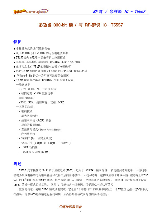
正 常 读 模 式 (Regular-read Mode)
第一个被传送数据的区是 1 区,当最后的区传送到位时,读从 1 区重新开始。但其中的 0 区一般不被传送, 然而模式寄存器不断用 EEPROM 0 区内容刷新。
④ 存储记忆体结构图 (Memory Map)
4
RF 读 / 写辨识 IC - T5557
可 追 溯 数 据 结 构 (Traceability Data Structure)
第 1 页的块 1 和块 2 包含可追溯数据,并且被 Atmel 在制造测试期间进行其数据规划并且锁定。块 1 最 开始的字节被选定到‘E0’hex,第二个字节是作为 Atmel 制造商的身份按 ISO/IEC 15963-1 所定义的配置分 类(ACL).(=‘15’hex)。第三字节的 8 bit 作为 IC 参考字节被使用( ICR 40~47 bit)。这 3 个部分是关系 到T5557的IC或制造版本的定义位。
RF 读 / 写辨识 IC - T5557
多功能 330-bit 读 / 写 RF-辨识 IC --T5557
特征
● 非接触方式的读/写数据传输 ● 从 100 KHz 到 150 KHz 的无线电电波频率 ● T5557 是与 e5550 产品兼容扩大应用模式 ● 小容量, 其结构与国际标准 ISO/IEC 11784 / 785 相容 ● 在芯片之上有 75 pF 的谐振电容器 (掩模选项) ● 包括 32 bit 密码区在内的 7 x 32 bit 的 E2PROM 数据记忆体 ● 单独的 64 bit 记忆体为厂商可追溯的数据区 ● 32-bit 配置寄存器在 E2PROM 中可作如下设置:
多普康 TC55V 运动控制系统 1-4 轴系列说明书

TC55V 运动控制系统1-4轴系列说明书北京多普康自动化技术有限公司安全须知使用本控制系统前,请您仔细阅读本手册后再进行相关的操作。
仔细阅读本操作说明书,以及用户安全须知,采取必要的安全防护措施。
如果用户有其他需求,请与本公司联系。
工作环境及防护:1.控制系统的工作温度为0-40℃,当超出此环境温度时系统可能会出现工作不正常甚至死机等现象。
温度过低时,液晶显示器将出现不正常的情况。
2.相对湿度应控制在0-85%。
3.在高温、高湿、腐蚀性气体的环境下工作时,必须采取特殊的防护措施。
4.防止灰尘、粉尘、金属等杂物进入控制系统。
5.应防护好控制系统的液晶屏幕(易碎品):使其远离尖锐物体;防止空中的物体撞到屏幕上;当屏幕有灰尘需要清洁时,应用柔软的纸巾或棉布轻轻擦除。
系统的操作:系统操作时需按压相应的操作按键,在按压按键时,需要食指或中指的指肚按压,切忌用指甲按压按键,否则将造成按键面膜的损坏,而影响您的使用。
初次进行操作的操作者,应在了解相应功能的正确使用方法后,方可进行相应的操作,对于不熟悉的功能或参数,严禁随意操作或更改系统参数。
由于使用产品不当,而造成危及人身、财产安全的责任,本公司概不负责。
系统的检修:当系统出现不正常的情况,需检修相应的连接或插座连接处时,应先切断系统电源。
再进行必要的检修。
未进行严格操作的技术人员或未得到本公司授权的单位或者个人,不能打开控制系统进行维修操作,否则后果自负。
系统保修说明:保修期:本产品自出厂之日起十二个月内。
保修范围:在保修期内,任何按使用要求操作的情况下所发生的故障。
保修期内:保修范围以外的故障为收费服务。
保修期外:所有的故障均为收费服务。
以下情况不在保修范围内:任何违反使用要求的人为故障或意外故障,尤其电压接反接错。
带电插拔系统连接插座而造成的损坏。
自然灾害等原因导致的损坏。
未经许可,擅自拆卸、改装、修理等行为造成的损坏。
其他事项:本说明书如有与系统功能不符、不详尽处,以系统软件功能为准。
V-CB564 V-CB574 V-CB584 产品说明书
ModelLanguagePage 20Material Size(W*H)Designer Designer ConfirmColor(cover/body)Part No. DescriptionDateNo.Date Chage RecordChange contentECO No.Weight 100g 123456789V -C B564***/V-CB574***/V-CB584*** English & A ribic220 x 1502008.02.14owner's manual3828FI5914G SHIPENGFEIRead and follow all instructions before using your vacuum cleaner to prevent the risk of fire,electric shock, personal injury,or damage when using the vacuum cleaner.This guide do not cover all possible conditions that may occur.Always contact your service agent or manufacturer about problems that you do not understand. This appliance complies with the following ECDirectives :-73/23/EEC,93/68/EEC-Low Voltage Directive–89/336EEC –EMC Directive.This is the safety alert symbol.This symbol alerts you to potential hazards that can kill or hurt you and others.All safety messages will follow the safety alert symbol and either the word “WARNING” or“CAUTION.” These words mean:This symbol will alert you to hazards or unsafe practices which couldcause serious bodily harm or death.This symbol will alert you to hazards or unsafe practices which could causebodily injury or property damage.Connecting the flexible hosePush the end of the head (1)on the flexible hose (2)into the attachment point on the vacuum cleaner.To remove the flexible hose from the vacuum cleaner, press on the button (3) situated on the head, then pull upwards. Assembling the tubes• Metal or plastic tube (34)- Fit together the two tubes by twisting slightly.• Telescopic tube (4)- Push spring latch (5)forward.- Pull out tube to required length.- Release spring latch to lock.• Elbow tube (28)The elbow tube is for uses such as cleaning under the sofa, table and bed easily.- Fit the elbow tube onto the end of the telescopic tube and the grip handle.-If you pull the latch (29), the elbow tube can be bent.- If you stretch the elbow tube, it is returned to its position.Using the cleaning head and Accessory Nozzles(depending on model)Fit the large cleaning head onto the end of the tube.• The 2-position head (6) is equipped with a pedal (7)which allows you to alter its position according to the type of floor to be cleaned.Hard floor position(tiles, parquet floors...). Press on the pedal to lower the brush.Carpet or rug position.Press on the pedal to lift the brush up.• Hard Floor Nozzle (30)Efficient cleaning of hard floors (wood, linoleum, etc.)• Crevice Tool (8)For vacuuming in those normally inaccessible places i.e. reaching cobwebs, or down the side of a sofa!• Dusting brush (9)For vacuuming picture frames, furniture outlines, books and other uneven objects.• Upholstery Nozzle (10)For vacuuming uphostery, mattresses, etc. The thread collectors help to pick up the threads and fluff.How to plug in and usePull out the supply cord to the desired length and plug into the socket.Press button (12)to start the vacuum cleaner. To stop it press the button (12)again. Adjusting the power level (depending on model)• The flexible hose handle (13)has a manual air flow regulator (14)which allows you to briefly reduce the suction level.••Electronic power control (15) Suction capacity increases smoothly up to MAX.How to UseElectronic power control(26)OFF:Power off MIN:Low powerMAX:Full powerPark-System(16)For short breaks during vacuuming, forexample to move a small piece of furnitureor a rug, use the Park system to supportthe flexible hose and cleaning head.ï Slide the hook attached to the large cleaningtool into the slot on the rear of the appliance.Storage(17)When you have switched off and unpluggedthe appliance, press the button (11) toautomatically rewind the cord.You can move or store your appliance in avertical position by sliding the hook on thelarge cleaning head into the clip on theunderside of the appliance.Changing the dust bagThe dustbag needs changing when thecleaner is set to maximum power and thecleaner head is off the floor but the ìbag fullîindicator window(18) is completely colouredred.Even if the dustbag does not appear to befull at this stage, it should be changed, asvery fine dust can clog up the pores of thedust bag.• Turn off the appliance and unplug it.• Open the cover by pressing the hook(19)and lifting it up until it snaps into place.Your appliance is equipped with either apaper dust bag (20)or a fabric dust bag(25).(depending on model)• Take hold of the dust bag by the handle and pull. Remove the bag and throw it away.• To refit a new bag push the cardboardsupport of a new bag into the bag mount (21) until it will go no furthe r.If your appliance is fitted with a fabric dust bag follow the same instructions as above.Empry it and replace it(25). Do not wash it. Note: as the appliance is fitted with a safety device which checks that the bag is in place you cannot close the lid if the bag is not fitted correctly.Cleaning the motor filterThe motor filter is situated inside the appliance between the dust bag and the motor. Each time that you change the air outlet filter we advise you to remove the motor filter(22) and to clean it by tapping to remove the dirt and then replacing it in the vacuum cleaner.Changing the air outlet filters Depending on the model you have chosen your appliance is equipped with different types of filters : foam filter or electrostatic filter(24)or anti-odour charcoal filter or washable HEPA filter(27).• To change these filters remove the cover of the filter compartment(23)situated at the rear of the appliance.• The foam filter should be cleaned regularly by tapping it to remove the dirt.• The electrostatic filter or anti-odor charcoal filter should be changed regularly. (approximately every 6 bag changes)• Wash the washable HEPA filter with water at least once a year.Check that the appliance is correctly plugged in and that the electrical socket is working.• Stop the appliance and unplug it.• Check that the tubes, flexible hose and cleaning tool are not blocked.• Check that the dust bag is not full.Replace if necessary.• Check that the air outlet filter is not blocked. Replace if necessary. What to do if your appliance does not work?What to do when the suction performance reduces?/ P/No.3828FI5914G- 2 -- 3-- 3 -Dd•îM lW«∞J N d°O W∞LÀ•±WØN d°O W,«∞d bÅd¥o,√˺bËL«∞∑F K OL U§d«¡…J M§U¡Æ‹O l∑ª«∞Lßb«ÂÆ∂«qq≥c««∞b∞OqL¥Ø«∞J N d°O W,ôAL K W«∞L∫∑W·Ë«∞Edqn®ªU’∞úU°W√Ë≈º,√ËŪbÂJ M¢K∑«∞Lß´M b«§uœ√¥W˱wA≠•U∞WM l¢H N L N U¥∑u«≠≥c«Boôö‹Jœ«z L U°H MbÀ.«¢∫¢«∞LÆbBw√˱Wqªb«∞∑«∞wMHªËÆU≤uiÊ«∞H u∞XËÆU≤uME.,CÊEC/633/98-E«∞LlÆu«≤O«ô¢±N U“E«∞π∫sUœ«_37/32/CEw:-˰˸¢M∂O te∞Kö±W.º±¸≥c«u≥√Ë¢R–¥psJp√Ê¢I∑K«üd¥s.î¥LX√Ë√≤±e{bc««∞d≥¥M∂Np«∞LwL K W«∞∑ª∫∑U©d«∞L¸U z qØßr«∞o¢Kwqe““±¸ö±WغqË¢F MwØK LWU∞LW∞Kº“¢W∫N I NRA¢M∂O tG√Ë“c¥d”C””¢M∂O t“AO I TNU±U¥Kw:cÁ«∞J K L U‹w¢F M≥±M W«ü‹UË«∞∑¨O d≈∞Ív¢RœÆbßwec««∞d≈∞≥pL U¸¥M∂Nv±«∞L«∞Ld√ËU©ªDî«∞u≠U….b¥WO d…√˺≈ÅU°W§±«üUM W‹¨O dÆb≈∞vÍ¢RœwßË«∞∑ª±e≥pL U¸¥M∂N≈∞c««∞d√Ëvd«∞LU©«∞Ln«∞LL‹¢K.∑K J U≈U°WÅ√˧ºb¥W- 5 -- 6 -- 7 -- 8 -- 9 -/ P/No.3828FI5914G。
迪宝电子秤清风、劲风基本操作手册(汉字屏)
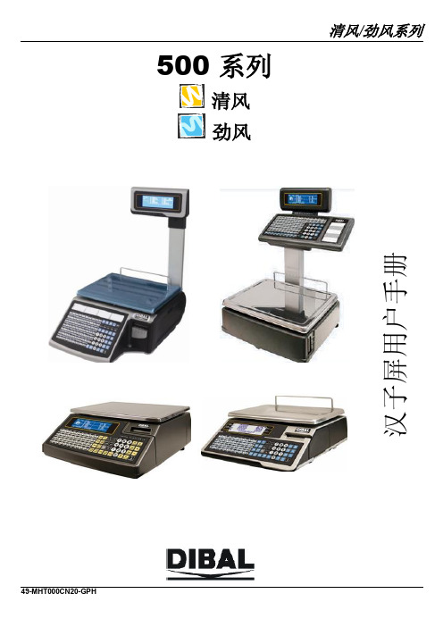
500 系列
清风 劲风
49-MHT000
清风/劲风系列
目录
1. 介绍 ............................................................................................................................................................................. 1 1.1. 简介 ..................................................................................................................................................................... 1 1.2. 主要特点 ............................................................................................................................................................. 1 1.3. 电子秤规格 ......................................................................................................................................................... 2 1.3.1. 概况..............................................
TC1664R_多语言台式三角屏使用说明V100资料
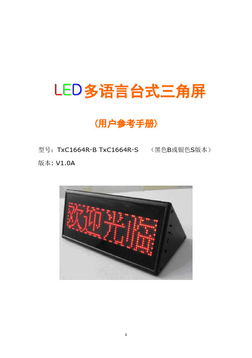
多语言台式三角屏(用户参考手册)型号:TxC1664R-B TxC1664R-S (黑色B或银色S版本)版本: V1.0A型号表:1.综述:1.1组成本台式屏的组成如下图所示, 由台式屏、USB通讯线与CD-ROM软件光盘组成.(本产品结构采用框架式设计,强度高,重量轻,美观大方,经久耐用.面罩材料采用2.0MM厚进口红茶色有机玻璃,堵头材料采用进口工程塑料,框架材料采用进口铝型材),产品尺寸附六面图。
1.2本台式屏的特点1)16 x 64 点阵。
2)多国语言,一行静止可以显示四个中文/日文/韩文/繁文,8个西文/俄文等。
2) 6条文本信息,2条图像信息, 可以使用图像信息显示公司LOGO,印度文,泰文,阿拉伯文等…3) 11个生动的动画图标:4) 内置两个按键, 一个键选择播放8条信息中的某一条或8条信息连播, 另一个键选择显示屏的亮度,共有四级亮度可调 (25%, 50%,75%, 100%).5) 强大的计算机管理软件平台,可以支持 RS232 /或USB 通讯.6) 内置大容量聚合物锂电池, 充电2个小时,可以连续使用16个小时(25%亮度).7) 开机前,按住2个按键, 再打开电源, 画面将翻转180度显示.1.3 认识您手中的台式屏:如下图所示,台式屏的右边(侧面看),共有四个功能键,第一个按键调节显示屏的亮度,第二个按键是信息选择键(可预先输入八条信息内容,每按一次显示其中一条信息内容).第三个是一个通讯/充电USB 接口,第四个是电源开关。
特别注意:USB线端口较为脆弱,插上RS232端口充电或通迅时,请勿用力插拔,避免损坏RS232端口,否则将引起通讯或充电不正常。
1.4 如何打开/关闭台式屏首先,请确认名片屏的电池仍然有电量, 把上图所示的开关置于“打开”的状态, 则预先输入的节目信息就会显示出来. 当把开关置于“关闭”状态时,或电池电量耗尽时, 显示屏则会自动关闭.1.5 如何使用您的台式屏此产品广泛应用于酒店吧台、公司前台、会议室、商店柜台,出租车顶部,店门口,道路指示等地方2. 软件操作说明USB 通讯计算机管理软件允许您通过一台PC机向台式屏输入您编辑的信息.2.1 打开光盘,将出现如下图所示安装指南界面:2.2 点击Install 安装程序,将出现如下界面:2.3 分别点击第一条进行安装驱动程序和第二条进行安装软件程序。
TI产品中文版说明书
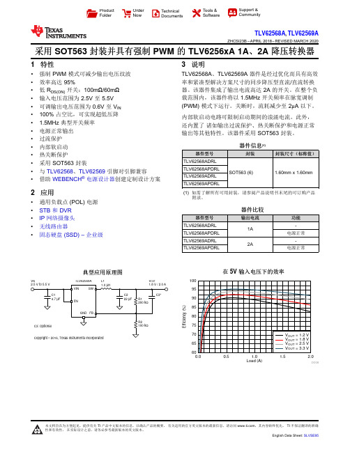
Load (A)E f f i c i e n c y (%)0.00.51.0 1.52.06065707580859095100D008V INV OUTL1TLV62569AProduct Folder Order Now Technical Documents Tools &SoftwareSupport &CommunityTLV62568A ,TLV62569AZHCSI23B –APRIL 2018–REVISED MARCH 2020采用SOT563封装并具有强制PWM 的TLV6256xA 1A 、2A 降压转换器1特性•强制PWM 模式可减少输出电压纹波•效率高达95%•低R DS(ON)开关:100m Ω/60m Ω•输入电压范围为2.5V 至5.5V •可调输出电压范围为0.6V 至V IN •100%占空比,可实现超低压降• 1.5MHz 典型开关频率•电源正常输出•过流保护•内部软启动•热关断保护•采用SOT563封装•与TLV62568、TLV62569引脚对引脚兼容•借助WEBENCH ®电源设计器创建定制设计方案2应用•通用负载点(POL)电源•STB 和DVR •IP 网络摄像头•无线路由器•固态硬盘(SSD)–企业级3说明TLV62568A 、TLV62569A 器件是经过优化而具有高效率和紧凑型解决方案尺寸的同步降压型直流/直流转换器。
该器件集成了输出电流高达2A 的开关。
在整个负载范围内,该器件将以1.5MHz 开关频率在脉宽调制(PWM)模式下运行。
关断时,流耗减少至2μA 以下。
内部软启动电路可限制启动期间的浪涌电流。
此外,还内置了诸如输出过流保护、热关断保护和电源正常输出等其他特性。
该器件采用SOT563封装。
器件信息(1)器件型号封装封装尺寸(标称值)TLV62568ADRL SOT563(6)1.60mm x 1.60mmTLV62568APDRL TLV62569ADRL TLV62569APDRL(1)如需了解所有可用封装,请参阅产品说明书末尾的可订购产品附录。
TC55说明书
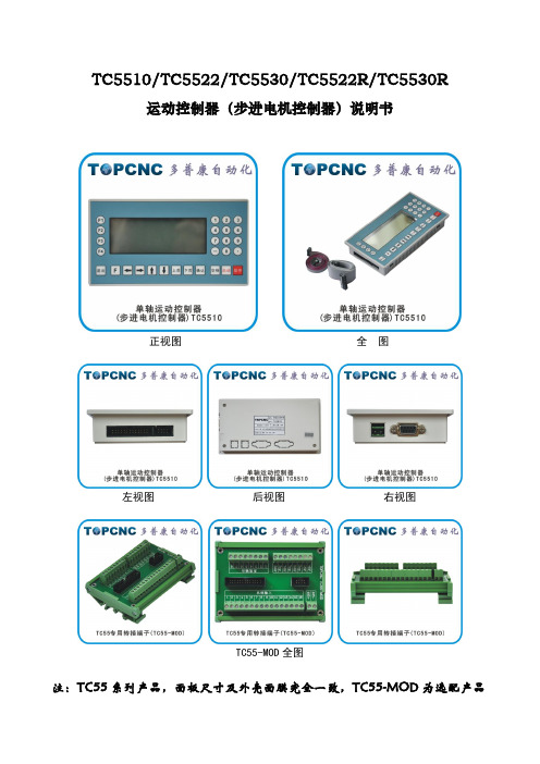
TC5510/TC5522/TC5530/TC5522R/TC5530R运动控制器(步进电机控制器)说明书正视图全图左视图后视图右视图TC55-MOD全图注:TC55系列产品,面板尺寸及外壳面膜完全一致,TC55-MOD为选配产品一、概述篇 (3)二、连接篇 (5)三、操作篇 (7)1.自动执行 (11)1.1实际运行 (11)1.2空运行 (11)1.3单步执行 (12)1.4终止程序 (12)2手动操作 (13)2.1手动高速 (13)2.2点动操作 (14)2.3回程序零 (14)2.4回机械零 (14)3程序管理 (16)3.1程序编辑 (16)3.2程序读入 (18)3.3程序删除 (19)3.4程序保存 (20)4参数设置 (20)4.2系统自检 (23)4.3 IO设置 (27)4.4用户管理 (29)四、编程篇 (30)五、附录篇 (52)一、概述篇TC55面板型运动控制器(数控系统)采用高性能32位CPU,驱动装置采用细分步进电机或交流伺服电机,配备液晶显示器,全封闭触摸式操作键盘。
该系统具有可靠性高,精度高,噪音小,操作方便等特点。
本控制器可控制1-3个电机运动,可实现点位、直线插补、圆弧插补等操作。
具有循环、跳转及简易PLC等功能。
简单、清晰的参数带给您方便和快捷的操作。
输入/输出的设置功能可方便您的使用和维修,适用于各类的1-3轴运动装置。
产品特点开机画面可自行修改控制器或上位计算机双模式编程独立24V电源反接保护IO光耦隔离输出短接保护手动正反转可同步外部开关控制简易PLC逻辑参数区密码可设定适用产品类型●数控钻床系统、数控车床系统、数控铣床系统、数控磨床系统●裁剪机控制系统、切割机控制系统、焊接控制系统、点胶机控制系统、送料控制系统●位移台、一维控制平台、二维控制平台、三维控制平台●螺纹机控制系统、锁螺丝机控制系统●喷涂生产线控制系统、装配生产线控制系统、记米器控制系统技术特点●自动执行:可实现实际运行、空运行、单段执行、终止程序、启动和暂停功能●手动操作:可实现手动高、低速、点动操作、回程序零、回机械零等操作。
巴鲁夫 工业 RFID系统 产品手册说明书

Industrial RFID systems MANAGING ALL YOUR DATABalluff offers you a wide selection of data carriers and read/write heads for LF, HF and UHF applications. With the BIS V multi-frequency processor unit, all systems can be combined with each other. This adds flexibility and saves costs through lower inventory levels.Industrial RFID systems – managing all your dataAutomatic identification and tracking in productionTHE PERFORMANCE RANGEYour Balluff solutionsn HF RFID system (13.56 MHz) BIS M n LF RFID system (70/455 kHz) BIS C n LF RFID system (125 kHz) BIS L n UHF RFID system (860/960 MHz) BIS UGo online to individually configure your own system www.balluff.de/go/rfid-configuratorIO-LINK ALL-IN-ONE BIS V PROCESSOR UNIT1 Network block2 Read/write heads with IO-Link3 Data carriers4 Read/write heads with integrated processor unit5 Universal processor unit6 Read/write heads2266433315UHF by country-specific frequencies1 South Korea LF: 125 kHz HF: 13.56 MHzUHF: 917...920.8 MHz 2 JapanLF: 125 kHz HF: 13.56 MHzUHF: 916.7...920.8 MHz 3 ChinaLF: 125 kHz HF: 13.56 MHzUHF: 840.5...844.5 MHz 4 AustraliaLF: 125 kHz HF: 13.56 MHz UHF: 920...926 MHz5 South Africa LF: 125 kHz HF: 13.56 MHzUHF: 865.6...867.6 MHz 6 EuropeLF: 125 kHz HF: 13.56 MHzUHF: 865.6...867.6 MHz 7 USA/Canada/Mexico LF: 125 kHz HF: 13.56 MHz UHF: 902...928 MHz 8 BrazilLF: 125 kHz HF: 13.56 MHzUHF: 902...907.5 MHzWHAT ARE THECONSEQUENCES OF THE DIFFERENT FREQUENCIES?Briefly stated, different frequencies mean different working ranges, since the frequency determines the range. The frequency also affects the coupling behavior (see: How the system components communicate).LF is best suited for close range and for difficult conditions such as metallic surroundings. LF is therefore often used in tool identification.HF is ideal for parts tracking at close range up to 400 mm. With HF you can process and store larger quantities of data at high transmission speeds.UHF typically communicates at a range of 6 m distance. UHF allows simultaneous reading of multiple data carriers (multi-tagging).System frequenciesWorking range of the Balluff BIS RFID systemsSYSTEM STRUCTURERFID requires three main components. These form an RFID system:–■Data carrier (data storage)–■Read/write head (data transmission)–■Processor unit (data processing and communication)The system components in detail–■Data carrier (Tag/Data Carrier)Stores all kinds of data which is read or written by computers or automation equipment. The data carrier antenna sends and receives the signals. Read/write versions are available in various memory capacities and with various storage mechanisms.– Passive data carriers: without power supply – Active data carriers: with power supply–■Read/write headProvides power to the data carrier, reads its data and writes new data to it. It sends this data to the processor unit where the data is further processed. –■AntennaTransmits the power.– HF-/LF systems: Antenna is integrated in the read/write head– UHF systems: Usually passive antennas without read/write head electronics (integrated into the processor unit).–■Processor unitUsed for signal processing and preparation. It typically includes an integrated interface for connecting to the controller/PC system.UHF system: The read/write function can be integrated into the processor unit, so that only a passive antenna and the data carrier are required.How the system components communicateThe data carrier and read/write head connect via the frequency-dependent coupling.With UHF the coupling is via electromagnetic waves, and for LF and HF the coupling is inductive.Components of a HF/LF systemData carrier Read/write head Processor unitUsed at close range, the data carrier must be placed exactly within the read range of the read/write head.Components of a UHF systemData carrier Antenna withProcessor unitread/write head electronicsData carrier Passive antennaProcessor unit withread/write head electronicsIn UHF systems close placement of the data carrier in front of the antenna is not necessary because of the large working range. Still, there are a few rules (see: What to know about UHF systems).Various industry standards are in place both for theLF/HF range and for UHF for communication between the system components. These specify how the information is transmitted. There are also proprietary manufacturer-specific solutions available (see: What you need to know about LF/HF systems/UHF systems).SYSTEM CHARACTERISTICSWhy data storage is importantSelection of the data storage determines where data can be processed and with which components. You can use either of two storage concepts: the central database and decentralized data retention.Central data storage–■All data records are stored in a central database –■Data carrier is simply an identifier –■Mainly for reading informationCan be LF, HF or UHF systems, but mainly used with UHF systemsDecentralized data retention–■All data records are stored on data carriers –■The data carrier stores the identifier and all data records (no central database)–■For both reading and writing informationMainly used with HF/LF systemsWHAT YOU NEED TO KNOW ABOUT LF/HF SYSTEMSIn brief, the read/write distance in LF/HF systems is affected by the antenna shape and the traverse speed.When installing the data carriers the installation conditions and close proximity of metal play a role.Antenna shapeData carriers and read/write heads are constructedwith a rod or round antenna. To achieve the best results the antenna shape must be identical to that of the read/write head. This means: Use rod antenna with rod antenna or round antenna with round antenna.The antenna shape determines different field distributions and read distances. It also determines the active communication field.Ideal working rangeRound antenna–■The lobe of the antenna field is distributed evenly and symmetrically–■No polarization or directionality, even offset.This means the data carrier and read/write head Rod antenna–■The lobe of the antenna field is distributed unevenly and has additional sidelobes–■The is polarization and directionality, which allows greater read distances than with a round antenna–■Identical orientation of the data carrier and read/write head is important in order to achieve greater read distancesInstalling data carriersAccount for distance to metalTo reach the specified read/write distance, a data carrier in a metallic environment must be mounted at a certain distance from metal and within a certain metal-free clear zone. The exact specifications can be found in the data sheets. The following distinctions are made:–■Flush in metalThe sensing surface can be mounted flush on the surface of steel so that it is even with adjacent areas. The range here is less than for differently constructed/installed data carriers of the same size.–■On metalThe sensing surface must not be in contact or surrounded by steel.–■Metal-free (clear zone)The entire area of the data carrier must be kept clear of any type of metal.12365874Data carriers with various memory types are available Traditional memory chips are EEPROM and FRAM.Both types use inductive coupling for power supply and data transmission. They differ in the maximum number of write cycles.–■EEPROM (Electrical erasable programmableread only memory): 100,000 to 1,000,000 write cycles –■FRAM (Ferro-electrical random access memory): 1010 write cyclesHow traverse speed, read/write distance and data transmission time relate to each otherFor reliable data transfer between read/write head andDynamic read/write modeThe data carrier passes by the read/write head without stopping. This should be as close as possible to achieve a long read/write path.How to calculate the traverse speed for dynamic applications Traverse speed (v)Offset (s)=At least 315 mm of offset is required to read the data within a dwell time of 45 ms. Assuming the maximum offset is 340 mm, the read distance must be configured to be very short. The greater the offset of the read/write head, the greater the distance between data carrier and read/write head can be.Important industry standards–■ISO 15693International series of standards for non-contacting chip cards, identification systems and access controls. Operates at a frequency of 13.56 MHz and is the prevailing standard in automation.ISO 15693 defines the protocols for communication between data carrier and read/write head. The datacarriers and read/write heads from different suppliers are generally compatible if they adhere to the same standard. –■ISO 14443International series of standards for non-contact chipcards. These are used in identification systems and access controlling, but also for payment applications such as credit cards, public transportation tickets, etc. Operates at a frequency of 13.56 MHz.In contrast to the ISO 15693 standard, ISO 14443specifies that the data carrier and read/write head carry a manufacturer-specific identifier. Only if the identifiers agree can they communicate with each other.Balluff uses the most commonly accepted contactless chip technology NXP Mifare. This complies with ISO-Standards ISO 7816 and ISO 14443A.High performance solutions from BalluffIn addition to the industry standards there are proprietary systems that are not described by any standard. For example, high-performance solutions from Balluff that are faster and process more data than these industry standards allow. Here the following components are used:–■High-memory data carriers: Data carriers with a memory capacity > 8 kilobytes.–■High-speed data carriers: Combined with the associated read/write heads you can achieve up to eight times greater read speeds than applications that fall under DIN ISO 15693.WHAT YOU NEED TO KNOW ABOUT UHF SYSTEMSPower transmission between data carrier and read/write head is essential for optimal function of a UHF RFID system. Whether and how the antennas need to be aligned with each other depends on the type of polarization of the antennas.Relationship between antenna polarization and data carrier orientationThe polarization of a UHF antenna is determined by the direction of the electrical field of the wave.–■Linear polarized antennasThe electrical field runs either vertical or horizontal to be identically aligned in order to transmit power.–■Data carrier antennaIn UHF systems the coupling is electromagnetic. To transmit data the data carrier‘s antenna converts electromagnetic waves and high-frequency alternating current into each other. Here the polarization direction of the sending antenna and the orientation of the data carrier must be selected correctly. (See illustration for how to achieve optimal power transmission).Construction of a UHF data carrierUHF data carriers with a dipole antenna are often selected (see illustration above). Many other antenna shapes are available as well. These offer particular properties and determine the form factor of the data carrier.Other form factors for UHF data carriersTypical UHF industry standards–■ISO/IEC 18000-6:2013International series of standards that provide the general description of the air interface and signal transmission. The latest standard ISO 18000-63 was published in 2015.–■EPC Class1 Gen2Was published by the standardization organization EPC global, which develops voluntary standards. EPC Class 1 Gen2 Version 2.0.1 is fully compatible with ISO 18000-63.This compatibility mans you can use the same hardware infrastructure and the same data carriers both in an ISO standard environment and an EPC environment.Both standards are suitable for worldwide use. You must however take note of the various national RF regulations.UHF antenna field requires specific test scenariosIn brief: Since the surroundings affect the antenna field, you must perform the closest possible simulation of the ambient conditions.The UHF antenna beams its signal in a wide opening angle. Undesired reflections and absorption in a UHF RFID system Typical ideal antenna fieldin overlapping of wavetrains. Overall it can result in local fields with higher and lower field strengths, or even field collapses (read holes).If a data carrier finds itself in such a read hole, it can no longer communicate with the read/write head.Headquarters Balluff GmbHSchurwaldstrasse 973765 Neuhausen a. d. F.GermanyPhone +49 7158 173-0Fax +49 7158 5010******************D o c . n o . 949747E N · I 20 · S u b j e c t t o c h a n g e s .CONTACT OUR WORLDWIDE SUBSIDIARIES。
LTC1163CS8#PBF;LTC1165CN8;LTC1165CN8#PBF;LTC1165CS8;LTC1165CS8#PBF;中文规格书,Datasheet资料

MOSFET DriversSFEATUREs Operates from 1.8V to 6Vs0.01µA Standby Currents95µA Operating Current per Channel at 3.3Vs Fully Enhances N-Channel Switchess No External Charge Pump Componentss Built-In Gate Voltage Clampss Easily Protected Against Supply Transientss Controlled Switching ON and OFF Timess Compatible with 5V, 3V and Sub-3V Logic Families s Available in 8-Pin SOIC D UESCRIPTIOThe LTC1163/LTC1165 triple low voltage MOSFET drivers make it possible to switch supply or ground referenced loads through inexpensive, low R DS(ON) N-channel switches from as little as a 1.8V supply. The LTC1165 has inverting inputs and makes it possible to directly replace P-channel MOSFET switches while maintaining system drive polar-ity. The LTC1163 has noninverting inputs. Micropower operation, with 0.01µA standby current and 95µA operating current, coupled with a power supply range of 1.8V to 6V, make the LTC1163/LTC1165 ideally suited for 2- to 4-cell battery-powered applications. The LTC1163/LTC1165 are also well suited for sub-3V, 3.3V and 5V nominal supply applications.The LTC1163/LTC1165 internal charge pumps boost the gate voltage 8V above a 3.3V rail, fully enhancing inexpen-sive N-channels for high- or low-side switch applications. The LTC1163/LTC1165 are available in both an 8-pin DIP and an 8-pin SOIC.SUPPLY VOLTAGE (V)GATEOUTPUTVOLTAGE(V)26810418LTC1163/65 • TA02426121416315MOSFET Switch Gate Voltage 2-Cell Triple High-Side SwitchU SA OPPLICATIs PCMCIA Card 3.3V/5V Switchs2-Cell High-Side Load Switchings Boost Regulator Shutdown to Zero Standby Currents Replacing P-Channel Switchess Notebook Computer Power Managements Palmtop Computer Power Managements Portable Medical Equipments Mixed 3.3V and 5V Supply SwitchingUA OPPLICATITYPICAL12LTC1163/LTC1165SYMBOL PARAMETER CONDITIONSMIN TYP MAXUNITS I QQuiescent Current OFFV S = 1.8V, V IN1 = V IN2 = V IN3 = V OFF (Note 1,2)0.011µA V S = 3.3V, V IN1 = V IN2 = V IN3 = V OFF (Note 1,2)0.011µA V S = 5V, V IN1 = V IN2 = V IN3 = V OFF (Note 1,2)0.011µA Quiescent Current ONV S = 1.8V, V IN = V ON (Note 2,3)60120µA V S = 3.3V, V IN = V ON (Note 2,3)95200µA V S = 5V, V IN = V ON (Note 2,3)180400µA V INH Input High Voltage 1.8V < V S < 2.7V q 80% × V S V 2.7V < V S < 6V q 70% × V SVV INL Input Low Voltage 1.8V < V S < 6V q 15% × V SV I IN Input Current 0V ≤ V IN ≤ V Sq±1µA C IN Input Capacitance 5pF V GATE – V SGate Voltage Above SupplyV S = 1.8V, V IN = V ON (Note 2)q 3.5 4.1 6.0V V S = 2V, V IN = V ON (Note 2)q 4.0 4.6 7.0V V S = 2.2V, V IN = V ON (Note 2)q 4.5 5.2 8.0V V S = 3.3V, V IN = V ON (Note 2)q 6.08.0 9.5V V S = 5V, V IN = V ON (Note 2)q5.09.013.0V t ONTurn-ON TimeV S = 3.3V, C GATE = 1000pF Time for V GATE > V S + 1V 40120400µs Time for V GATE > V S + 2V 60180600µs V S = 5V, C GATE = 1000pF Time for V GATE > V S + 1V 3095300µs Time for V GATE > V S + 2V40130400µsA UG WA WUW A R BSOLUTEXI TI SOperating Temperature RangeLTC1163C/LTC1165C........................... 0°C to 70°C Storage Temperature Range................ –65°C to 150°C Lead Temperature (Soldering, 10 sec)................. 300°CSupply Voltage ......................................................... 7V Any Input Voltage.......................... 7V to (GND – 0.3V)Any Output Voltage....................... 20V to (GND – 0.3V)Current (Any Pin)................................................. 50mAWUUPACKAGE/ORDER I FOR ATIOV S = 1.8V to 6V, T A = 25°C, unless otherwise noted.ELECTRICAL C C HARA TERISTICSLTC1163C/LTC1165C /3LTC1163/LTC1165ELECTRICAL C C HARA TERISTICSV S = 1.8V to 6V, T A = 25°C, unless otherwise noted.SYMBOL PARAMETER CONDITIONSMIN TYP MAX UNITSt OFFTurn-OFF TimeV S = 3.3V, C GATE = 1000pFTime for V GATE < 0.5V 2065200µs V S = 5V, C GATE = 1000pF Time for V GATE < 0.5V1545150µsLTC1163C/LTC1165C The q denotes specifications which apply over the full operating temperature range.Note 1: Quiescent current OFF is for all channels in OFF condition.Note 2: LTC1163: V OFF = 0V, V ON = V S . LTC1165: V OFF = V S , V ON = 0V Note 3: Quiescent current ON is per driver and is measured independently.Gate Voltage Above SupplySupply Current per Driver ONStandby Supply CurrentC C HARA TERISTICSU WA TYPICAL PERFOR CE SUPPLY VOLTAGE (V)0SU P P L Y C U R R E N T (µA )5 4 3 2 1 0 –11234LTC1163/65 • TPC0156SUPPLY VOLTAGE (V)V G A T E – V S (V )1210 8 6 4 2 01234LTC1163/65 • TPC0356SUPPLY VOLTAGE (V)0S U PP L Y C U R R E N T (µA )600 500 400 300 200 100 01234LTC1163/65 • TPC0256Input Threshold VoltageTurn-ON TimeTurn-OFF TimeSUPPLY VOLTAGE (V)0I N P U T T H R E S H O L DV O L T A G E (V )65 4 3 2 1 01234LTC1163/65 • T PC0456SUPPLY VOLTAGE (V)T U R N -O N T IM E (µs )600500 400 300 200 100 01234LTC1163/65 • TPC0556SUPPLY VOLTAGE (V)0T U R N -OF F T I M E (µs )300250 200 150 100 50 01234LTC1163/65 • TA06564LTC1163/LTC1165C C HARA TERISTICSU WA TYPICAL PERFOR CE PI FU CTIO SU U U Input PinsThe LTC1163 is noninverting; i.e., the MOSFET gate is driven above the supply when the input pin is held high.The LTC1165 is inverting and drives the MOSFET gate high when the input pin is held low. The inverting inputs of the LTC1165 allow P-channel switches to be replaced by lower resistance/cost N-channel switches while maintain-ing system drive polarity.The LTC1163/LTC1165 logic inputs are high impedance CMOS gates with ESD protection diodes to ground and therefore should not be forced below ground. The inputs can however, be driven above the power supply rail as there are no clamping diodes connected between the input pins and supply pin. This facilitates operation in mixed 5V/3V systems.Output PinsThe output pin is either driven to ground when the switch is turned OFF or driven above the supply rail when the switch is turned ON. The output is clamped to about 14V above ground by a built-in Zener clamp. This pin has a relatively high impedance when driven above the rail (the equivalent of a few hundred k Ω). Care should be taken to minimize any loading of this pin by parasitic resistance to ground or supply.Supply PinA 150Ω resistor should be inserted in series with the ground pin or supply pin if negative supply voltage tran-sients are anticipated. This will limit the current flowing from the power source into the LTC1163/LTC1165 to tens of milliamps during reverse battery conditions.OPERATIOUThe LTC1163/LTC1165 are triple micropower MOSFET drivers designed for operation over the 1.8V to 6V supply range and include the following functional blocks:3V Logic Compatible InputsThe LTC1163/LTC1165 inputs have been designed to accommodate a wide range of 3V and 5V logic families.The input threshold voltage is set at roughly 50% of the supply voltage and approximately 200mV of input hyster-esis is provided to ensure clean switching.The input enables all of the following circuit blocks: the bias generator, the high frequency oscillator and gate charge pump. Therefore, when the input is turned off, the entire circuit powers down and the supply current drops below 1µA.Standby Supply CurrentTEMPERATURE (°C)0S U P P L Y C U R R E N T (µA )5 4 3 2 1 0 –110203040LTC1163/65 • TPC07506070MOSFET Gate Drive CurrentGATE VOLTAGE ABOVE SUPPLY (V)1G A T E D R I V E C U R R E N T (µA )1010010004680.1210LTC1163/65 • TPC09Supply Current per Driver ONTEMPERATURE (°C)0S U P P L Y C U R R E N T (µA )300 250200150 100 50 010203040LTC1163/65 • TPC08506070/5LTC1163/LTC1165OPERATIOUGate Charge PumpGate drive for the power MOSFET is produced by an internal charge pump circuit which generates a gate volt-age substantially higher than the power supply voltage.The charge pump capacitors are included on chip and therefore no external components are required to generate gate drive.Controlled Gate Rise and Fall TimesWhen the input is switched ON and OFF, the gate is charged by the internal charge pump and discharged in a controlled manner. The charge and discharge rates have been set to minimize RFI and EMI emissions.BLOCK DIAGRA W(One Channel)APPLICATIO S I FOR ATIOW UU U Logic-Level MOSFET SwitchesThe LTC1163/LTC1165 are designed to operate with logic-level N-channel MOSFET switches. Although there is some variation among manufacturers, logic-level MOSFET switches are typically rated with V GS = 4V with a maximum continuous V GS rating of ±10V. R DS(ON) and maximum V DS ratings are similar to standard MOSFETs and there is generally little price differential. Logic-level MOSFETs are frequently designated by an “L” and are usually available in surface mount packaging. Some logic-level MOSFETs are rated with V GS up to ±15V and can be used in applications which require operation over the entire 1.8V to 6V range.Powering Large Capacitive LoadsElectrical subsystems in portable battery-powered equip-ment are typically bypassed with large filter capacitors to reduce supply transients and supply induced glitching. If not properly powered however, these capacitors may themselves become the source of supply glitching.For example, if a 100µF capacitor is powered through a switch with a slew rate of 0.1V/µs, the current during start-up is:I START = C(∆V/∆t)= (100 × 10–6)(1 × 10⁵)= 10AObviously, this is too much current for the regulator (or output capacitor) to supply and the output will glitch by as much as a few volts.The startup current can be substantially reduced by limit-ing the slew rate at the gate of an N-channel as shown in Figure 1. The gate drive output of the LTC1163/LTC1165is passed through a simple RC network, R1 and C1, which substantially slows the slew rate of the MOSFET gate to approximately 1.5 × 10⁻⁴V/µs. Since the MOSFET is operating as a source follower, the slew rate at the source is essentially the same as that at the gate, reducing the startup current to approximately 15mA which is easilyGATEINPUT6LTC1163/LTC1165APPLICATIO S I FOR ATIOW UU U Figure 1. Powering a Large Capacitive Loadon a 3.3V supply which is compatible with 5V TTL and CMOS logic. (The LTC1163/LTC1165 cannot however, be driven by 3V logic when powered from a 5V supply because the threshold is approximately 2.5V.)TYPICAL APPLICATIO SUPCMCIA Card 3.3V/5V V CC SwitchNOTE: USE LTC1163 WITH NONINVERTING PCMCIA CONTROLLERSmanaged by the system regulator. R2 is required to eliminate the possibility of parasitic MOSFET oscillations during switch transitions. It is a good practice to isolate the gates of paralleled MOSFETs with 1k resistors to decrease the possibility of interaction between switches.Mixed 5V/3V SystemsBecause the input ESD protection diodes are referenced to ground instead of the supply pin, it is possible to drive the LTC1163/LTC1165 inputs from 5V CMOS or TTL logic even though the LTC1163/LTC1165 are powered from a 3.3V supply as shown in Figure 2. The input threshold voltage is approximately 50% of the supply voltage or 1.6VReverse Battery ProtectionThe LTC1163/LTC1165 can be protected against reverse battery conditions by connecting a 150Ω resistor in series with the ground pin or supply pin. The resistor limits the supply current to less than 24mA with –3.6V applied.Because the LTC1163/LTC1165 draw very little currentwhile in normal operation, the drop across the resistor is minimal. The 3.3V µP (or control logic) can be protected by adding 10k resistors in series with the input pins.Figure 2. Direct Interface to 5V LogicV IN/7LTC1163/LTC1165Information furnished by Linear Technology Corporation is believed to be accurate and reliable.However, no responsibility is assumed for its use. Linear Technology Corporation makes no represen-tation that the interconnection of its circuits as described herein will not infringe on existing patent rights.TYPICAL APPLICATIO SU2-Cell to 3.3V, 5V and 12V High-Side Switch/Converterwith 0.01µA Standby Current3.3VµF3.3VUltra-Low Drop Triple 3.3V High-Side SwitchPCMCIA Card Socket V PP Switch/ReglatorV CC MMDF3N02HDPP = 0V, 3.3V,EN0 0 1 0 1EN1 0 0 1 1OUTPUT 0V 12V V CC HI-Z8LTC1163/LTC1165Linear Technology Corporation1630 McCarthy Blvd., Milpitas, CA 95035-7487(408) 432-1900 qFAX : (408) 434-0507 qTELEX : 499-3977© U SA OPPLICATITYPICAL S8 Package 8-Lead Plastic SOICPACKAGE DESCRIPTIO U3-Cell to 3.3V Ultra-Low Drop Regulator with 2 Ramped SwitchesµFMixed Voltage High- and Low-Side SwitchesN8 Package 8-Lead Plastic DIPDimensions in inches (millimeters) unless otherwise noted.–0.3818.2550.053 – 0.069 BSC/分销商库存信息:LINEAR-TECHNOLOGYLTC1163CS8#PBF LTC1165CN8LTC1165CN8#PBF LTC1165CS8LTC1165CS8#PBF LTC1163CS8LTC1165CS8#TR LTC1165CS8#TRPBF LTC1163CS8#TR LTC1163CS8#TRPBF LTC1163CN8LTC1163CN8#PBF。
(整理)贝斯特样本待审
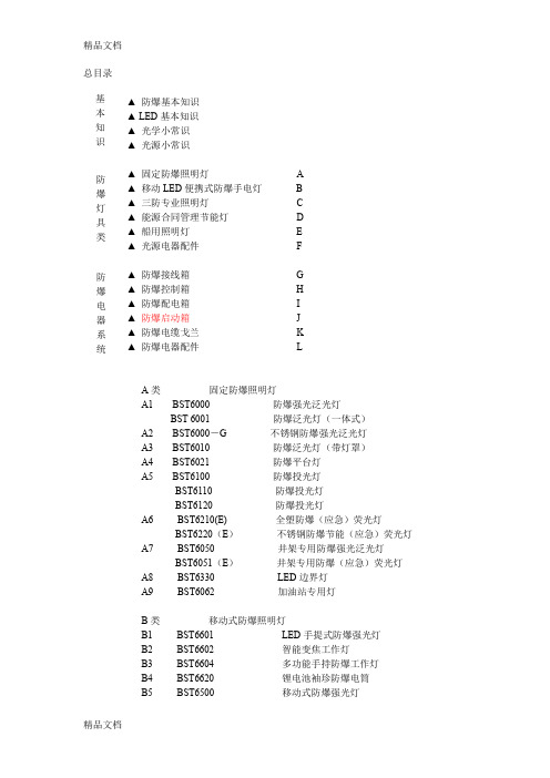
总目录 ▲ 防爆基本知识 ▲ LED 基本知识 ▲ 光学小常识 ▲ 光源小常识▲ 固定防爆照明灯 A ▲ 移动LED 便携式防爆手电灯 B ▲ 三防专业照明灯 C ▲ 能源合同管理节能灯 D ▲ 船用照明灯 E ▲ 光源电器配件 F ▲ 防爆接线箱 G ▲ 防爆控制箱 H ▲ 防爆配电箱 I ▲ 防爆启动箱 J ▲ 防爆电缆戈兰 K ▲ 防爆电器配件 LA 类 固定防爆照明灯A1 BST6000 防爆强光泛光灯BST 6001 防爆泛光灯(一体式) A2 BST6000-G 不锈钢防爆强光泛光灯 A3 BST6010 防爆泛光灯(带灯罩) A4 BST6021 防爆平台灯 A5 BST6100 防爆投光灯 BST6110 防爆投光灯 BST6120 防爆投光灯A6 BST6210(E) 全塑防爆(应急)荧光灯BST6220(E ) 不锈钢防爆节能(应急)荧光灯 A7 BST6050 井架专用防爆强光泛光灯 BST6051(E ) 井架专用防爆(应急)荧光灯 A8 BST6330 LED 边界灯 A9 BST6062 加油站专用灯B 类 移动式防爆照明灯B1 BST6601 LED 手提式防爆强光灯 B2 BST6602 智能变焦工作灯B3 BST6604 多功能手持防爆工作灯 B4 BST6620 锂电池袖珍防爆电筒 B5 BST6500 移动式防爆强光灯 基本知识 防爆灯具类防爆电器系统B6 BST6410 防爆强光头灯C类三防专业照明灯C1 BST6800 防眩泛光灯C2 BST6810 防眩泛光灯C3 BST6820 防眩泛光灯BST6840C4 大功率强光泛光灯BST6900BST6900C5防震高亮度投光灯BST6910C6 BST8760 节能路灯C7 BST8761 节能路灯D类能源合同管理节能灯D1 BST6860 LED节能泛光灯D2 BST6940 LED节能投光灯D3 BST8701 LED节能路灯D4 BST9807 洗墙灯D5 LED强光射灯D6 LED灯管E类船用照明灯E1 BST8900 荧光蓬顶灯E2 BST8901 荧光床头灯E3 BST8902 荧光走道灯E4 BST8903 荧光镜前灯F类光源电器F1 光源高显色石英金属卤化物灯、高压钠灯、荧光灯F2 镇流器:标准T8荧光灯电子镇流器、高强度气体放电灯阻抗式镇流器F3 电容器F4 触发器F5 1000W大功率灯用镇流器、触发起、电容器F6 防爆镇流器G 类防爆接线箱G1 BST-G-02型防爆接线盒G2 BST-DJX型防爆接线箱H类防爆控制箱H1 BST-DLK型防爆动力(照明)控制箱H2 BST-CZG型防爆操作柱I类防爆配电箱I1 BST-DB型井口专用电潜泵配电箱I2 BST-P-KZG型正压防爆控制柜I3 BST-DB隔爆型高压防爆接线箱J类BST-QD防爆起动配电箱(柜)J1 BST-QD-BP型防爆变频起动配电箱(柜)J2 BST-QD-R型防爆软起动配电箱(柜)J3 BST-QD-X型防爆星三角起动配电箱(柜)J4 BST-QDX型防爆磁力起动器配电箱(柜)K类防爆电缆戈兰K1 BST-DNEX型填料函K2 BST-A2F型填料函K3 丝堵L类防爆电器配件L1 BST-NG3 不绣钢防爆挠性连接管L2 BST-HJ 防爆活接头L3 BST-BCH 防爆穿线盒L4 BST-TN 防爆胶泥防爆基本知识基本知识防爆基本知识▲ 可燃性粉尘环境用电器设备分区▲爆炸性物质分类中国将爆炸性物质分为三类: I 类:矿井甲烷II 类:爆炸性气体混合物(含蒸汽、薄雾)III 类:爆炸性粉尘和纤维▲防爆电气设备的类、级、组设备组别温度 气体引燃温度 允许最高表面温度 T1 >450℃ ≤450℃ T2 >300℃ ≤300℃ T3 >200℃ ≤200℃ T4 >135℃ ≤135℃ T5 >100℃ ≤100℃ T6 >85℃ ≤85℃按设备的适用环境分为三类:I 类:矿井用II 类:工厂用III 类:爆炸性粉尘和纤维环境用 II 类设备分级分组:同气体分级、分组 分级:分为A 、B 、C 三级 分组:分为T 1~T6 I 类和III 类设备不分级,但III 类设备分为A 、B 型设备。
IC引脚功能及元器件代换
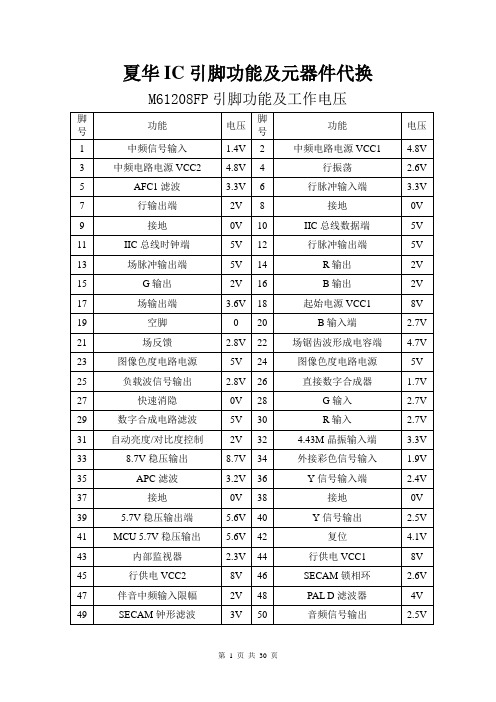
夏华IC引脚功能及元器件代换M61208FP引脚功能及工作电压
J系列CPU(SDA555X)各脚功能及电压
TDA16846功能脚简介
STR-G5653引脚功能及电压
ST6378引脚功能
TDA6210Q引脚功能
AN7583引脚功能
TA8720AN AV开关
SDA9380引脚功能
TDA8362引脚功能
厦华彩电各型号中周内置电容值
厦华彩电显像管、高压包及电路主要参数对照表(一)
第10 页共30 页
第11 页共30 页
第12 页共30 页
第13 页共30 页
第14 页共30 页
第15 页共30 页
第16 页共30 页
第17 页共30 页
第18 页共30 页
第19 页共30 页
厦华彩电行包代换表
第20 页共30 页
第21 页共30 页
第22 页共30 页
第23 页共30 页
第24 页共30 页
第25 页共30 页
开关变压器代用表
1/2W稳压管型号稳压值
场效应管K3116可用K2645代用。
D400可用C2344代用。
C2344可用C5248代用厦华彩电机型与CPU型号对应表。
TC55H系列运动控制器
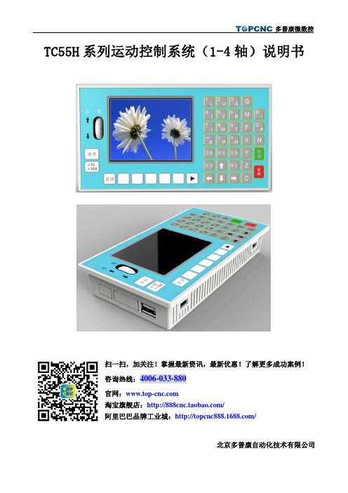
TC55H 系列运动控制系统(1-4轴)说明书北京多普康自动化技术有限公司扫一扫,加关注!掌握最新资讯,最新优惠!了解更多成功案例!咨询热线:4006-033-880官网:淘宝旗舰店:/阿里巴巴品牌工业城:/一、操作篇1.概述TC55H是北京多普康全新开发的新产品,可控制4个进给轴,1个模拟主轴,16路输入,8路输出,USB接口,支持U盘文件操作和程序运行,支持G代码编程。
1.1主要功能自动:自动加工运行,单段程序执行手动:手动高低速运行,手脉控制,当前选中轴程序回零,全部回程序零点,机械回零程序:编辑,读入,删除,另存,新建参数:控制参数,速度参数,输入参数,输出参数,厂值恢复USB:导入程序或开机图片密码:登陆用户,退出用户,修改密码外部手动:控制电机正反转,启动、暂停、报警、急停等程序指令:G指令和M指令隔离I/0口:带有与系统隔离的输入输出口模拟主轴输出:可接1路0~10V模拟主轴脉冲输出:4轴脉冲差分输出程序编辑:自动解释编辑指令1.2系统组成控制系统主要有以下部分组成● 3.5寸彩色液晶屏,分辨率320*240●触点按键阵列●4轴差分脉冲输出●输入/输出(16路光电隔离24V输入,8路光电隔离24V输出,单通道额定500mA)●1路模拟量主轴输出●1个面板型手轮,增量×1,×10,×100●1个USB接口,可插入U盘●最大程序行5000行,程序内存容量128M,可存100个加工程序1.3技术指标最小数据单位:0.001mm编程范围:±99999.999mm控制轴数:1~4轴(X,Y,Z,C)联动轴数:X,Y,Z,C轴可做直线插补,X,Y可做圆弧插补主轴数:1轴(S)各轴最大进给速度:9000mm/min(当脉冲当量为0.001mm时)插补:直线/圆弧电子齿轮:分子:1~99999,分母:1~999991.4尺寸z外形尺寸:长×宽×厚172×94×48mmz嵌入口尺寸:长×宽162×84mm,前面板厚4mm2.按键定义3.显示及操作方式3.1主界面系统上电后,跳过开机画面进入主界面,主界面显示坐标轴的位置,坐标的运行速度F及倍率,主轴的运行速度S及倍率,输入、输出口的状态。
atc中文手册
CAT24WC256 是一个256K 位串行CMOS E2PROM 内部含有32768 个字节每字节为8 位
CATALYST 公司的先进CMOS 技术实质上减少了器件的功耗CAT24WC256 有一个64 字节页写缓冲器
该器件通过I2C 总线接口进行操作
管脚描述
管脚名称 功能
A0 A1 地址输入
CAT24WC256 在接收到起始信号和从器件地址之后响应一个应答信号如果器件已选择了写操作
则在每接收一个8 位字节之后响应一个应答信号
当CAT24WC256 工作于读模式时在发送一个8 位数据后释放SDA 线并监视一个应答信号一旦
接收到应答信号CAT24WC256 继续发送数据如主器件没有发送应答信号器件停止传送数据并等待
件地址和它想读取的字节数据的地址执行一个伪写操作在CAT24WC256 应答之后主器件重新发送起
始信号和从器件地址此时R/W 位置1 CAT24WC256 响应并发送应答信号然后输出所要求的一
个8 位字节数据主器件不发送应答信号但产生一个停止信号
连续读
连续读操作可通过立即读或选择性读操作启动在CAT24WC256 发送完一个8 位字节数据后主器
CAT24WC256 监视总线并当其地址与发送的从地址相符时响应一个应答信号通过SDA 线
CAT24WC256 再根据读写控制位R/W 的状态进行读或写操作
应答信号
I2C 总线数据传送时每成功地传送一个字节数据后接收器都必须产生一个应答信号应答的器
件在第9 个时钟周期时将SDA 线拉低表示其已收到一个8 位数据
如果CAT24WC256 正在进行内部写操作将不会发送应答信号如果CAT24WC256 已经完成了内部写
操作将发送一个应答信号主器件可以继续对CAT24WC256 进行下一次读写操作
FUTABA T8FG最新中文说明书
中立测试[Neutral Test]对获得舵机摇臂的中立点位 置很有用。
途
舵机测试操作 1.移动光标到关闭[OFF]选项上,轻触 RTN 键切换到数据
用 业
输入模式。
商 通过触摸盘的 Scrolling 键选择测试模式[Test Mode]后 l 轻触 RTN 键确认。然后选中的模式开始闪烁。再次轻 禁 i 触 RTN 键改变模式(直到选中终点模式后,轻触 S1 键 严 ev 确认)。 d 移动[Moving]:每个舵机都重复操作。 流 - 中立点[Neutral]:每个舵机都被锁定在中立点位置。 y 2.移动光标到移动[Moving]或中立点[Neutral] 选项上, 交 r 轻触 RTN 键切换到数据输入模式。 习 c 通过触摸盘的 Scrolling 键选择关闭[OFF]选项后轻触 学 by RTN 键确认。停止测试。
前言:
经过一个多月的努力,FUTABA T8FG 英文版说明书关于《连接菜单》及直升机《模型菜单》章节终于翻译完成 了。
当初起心翻译该说明源自我在 5IMX 发的一个帖子,大意是号召大家将本说明拆分,动用群体力量各自翻译一 部分再整合成一本全中文化的说明书,可惜响应者寥寥趋近于无。
其实,那个时候我连该遥控器都没有!后来,我购入了亚拓 600EFLPRO,但遥控器还是没钱买。当时纠结于 10CG 与 T8FG,最终选择了 T8FG!不过,想要购入还得等段时间!
再挖坟就困难了!所以,现在的我也看开了,不求回复什么有建设性意见的话,只求保持帖子在第一页能让更多购
仅供 入该款遥控器的朋友能够尽快熟悉它的操作。 现在,《连接菜单》的章节也已经制作完成了,这次与直升机《模型菜单》进行了整合更方便大家的阅读,至 于翻译质量,我仍然不敢保证。也许会出 V0.3 版本,也许会翻译其它章节,谁知道呢?到时再说吧!
浙江德英QTZ80A说明书(TC5512)
9.6 电气设备安装 ……………………………………………65
9.7 电路图 …………………………………………………… 66
图9-6 电路图 控制部份(液力) ……………………………66
图9-7 电路图 起升部份(液力) ……………………………67
2. 起重机技术性能:
臂
架
长
度
(m)
55
幅度R (m)
2.5~
14.00
16
18
20
23
25
28
30
32
34
起重量
Q(t)
α=4
6.00
5.25
4.60
4.08
3.48
3.16
2.77
2.55
2.36
2.20
α=2
3.00
幅度R (m)
36
38
40
42
44
46
48
50
53
55
起重量
Q(t)
α=4
2.05
7.5附着尺寸 ………………………………………………47
7.6附着检测和张紧…………………………………………48
7.7混凝土基础强度…………………………………………48
8. 配套产品技术性能 …………………………………… 49
8.1起重量限制器 …………………………………………49
8.2起升减速器 ……………………………………………49
图3-2固定式底节
图3-1大底架
3.1.2 塔身(见图3-3)
塔身由若干个标准节组成,根据塔机的高度,确定标准节的数量,标准节是由主弦杆,水平腹杆,斜腹杆等组焊而成的空间桁架结构,每节长为2.8m,截面为1.645m×1.645m ,下塔身有五节,其特点是主弦杆采用每端有三个连接套,而塔身标准节的主弦杆是采用每端只有二个连接套。
瑞特拉电子产品购买指南说明书
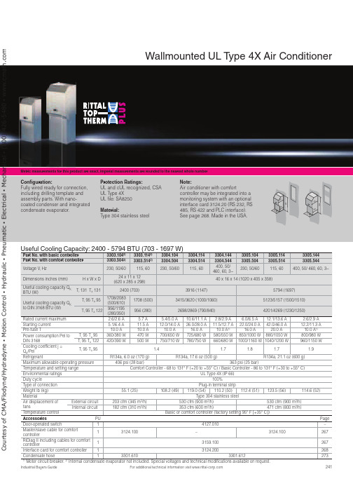
241For additional technical information visit Metric measurements for this product are exact, imperial measurements are rounded to the nearest whole numberUseful Cooling Capacity: 2400 - 5794 BTU (703 - 1697 W)Part No. with basic controller 3303.1042)3303.1142)3304.1043304.1143304.1443305.1043305.1143305.144Part No. with comfort controller 3303.5042)3303.5142)3304.5043304.5143304.5443305.5043305.5143305.544Voltage V , Hz230, 50/60115, 60230, 50/60115, 60400, 50/ 460, 60, 3~230, 50/60115, 60400, 50/ 460, 60, 3~Dimensions inches (mm)H x W x D24 x 11 x 12 (620 x 285 x 298)40 x 16 x 14 (1020 x 405 x 358)Useful cooling capacity Q KBTU (W)T i 131 T a 1312400 (703)3916 (1147)5794 (1697)Useful cooling capacity Q K to DIN 3168 BTU (W)T i 95 T a 951708/2083(500/610)1708 (500)3415/3620 (1000/1060)5123/5157 (1500/1510)T i 95 T a 122956/1195(280/350)956 (280)2698/2869 (790/840)4201/4269 (1230/1250)Rated current maximum 2.6/2.6 A 5.7 A 5.4/5.0 A 10.6/11.1 A 2.8/2.9 A 6.0/6.5 A 12.1/13.6 A 2.6/2.9 A Starting current 5.1/6.4 A 11.5 A 12.0/14.0 A 26.0/28.0 A 11.5/12.7 A 22.0/24.0 A 42.0/46.0 A 12.2/11.3 A Pre-fuse T 10.0 A 10.0 A 10.0 A 16.0 A 10.0 A 1)16.0 A 20.0 A 10.0 A 1)Power consumption Pel toDIN 3168T i 95 T a 95360/380 W 470 W 700/650 W 725/680 W 580/550 W 850/1000 W 880/1050 W 800/980 W T i 95 T a 122420/390 W500 W 750/710 W 780/750 W 660/680 W 1000/1160 W 1040/1200 W 960/1150 W Cooling coefficient j =Q K /PelT i 95 T a 95 1.4 1.7 1.8 1.7 1.9Refrigerant R134a, 6.0 oz (170 g)R134a, 17.6 oz (500 g)R134a, 21.1 oz (600 g)Maximum allowable operating pressure 406 psi (28 bar)363 psi (25 bar)Temperature and setting range Comfort Controller - 68 to 131° F (+20 to +55° C) / Basic Controller - 86 to 131° F (+30 to +55° C)Environmental ratings UL Type 4X (IP 66)Duty cycle 100%Type of connection Plug-in terminal strip Weight lb (kg)55.1 (25)108.2 (49)119.0 (54)110.2 (50)112.4 (51)123.5 (56)114.6 (52)Material Type 304 stainless steelAir displacement offans External circuit 203 cfm (345 m 3/h)530 cfm (900 m 3/h)530 cfm (900 m 3/h)Internal circuit 182 cfm (310 m 3/h)353 cfm (600 m 3/h)471 cfm (800 m 3/h)Temperature control Basic or comfort controller (factory setting 95° F [+35° C])Accessories PU Page Door-operated switch 14127.010–Master/slave cable for comfortcontroller13124.100–3124.100267RiDiag II including cables for comfortcontroller13159.100267Interface card for comfort controller 13124.200268Condensate hose 13301.6103301.6122731) Motor circuit breaker. 2)Internal condensate evaporator not included. Special voltages and technical modifications available on request.Wallmounted UL T ype 4X Air ConditionerCon guration:Fully wired ready for connection, including drilling template and assembly parts. With nano-coated condenser and integrated condensate evaporator.Protection Ratings:UL and cUL recognized, CSA UL Type 4XUL file: SA8250 Material:Type 304 stainless steel Note:Air conditioner with comfortcontroller may be integrated into a monitoring system with an optional interface card 3124.20 (RS 232, RS 485, RS 422 and PLC interface). See page 268. Made in the USA.000C o u r t e s y o f C M A /F l o d y n e /H y d r a d y n e ŀ M o t i o n C o n t r o l ŀ H y d r a u l i c ŀ P n e u m a t i c ŀ E l e c t r i c a l ŀ M e c h a n i c a l ŀ (800) 426-5480 ŀ w w w .c m a f h .c o242For additional technical information visit Metric measurements for this product are exact, imperial measurements are rounded to the nearest whole numberUseful Cooling Capacity: 8706 - 10525 BTU (2550 - 3083 W)Part No. with basic controller 3328.1043328.1143328.1443329.1043329.1143329.144Part No. with comfort controller 3328.5043328.5143328.5443329.5043329.5143329.544Rated operating voltage V , Hz 230, 50/60115, 50/60400, 50/460, 60, 3~230, 50/60115, 50/60400, 50/460, 60, 3~Dimensions inches (mm)H x W x D 65 x 16 x 15 (1650 x 405 x 388)Useful cooling capacity Q K BTU (W)T i 131 T a 1318706 (2550)10525 (3083)Useful cooling capacity Q K to DIN 3168 BTU (W)T i 95 T a 956860/8025 (2000/2350)8538/9392 (2500/2750)T i 95 T a 1224952/5772 (1450/1690)5464/5977 (1600/1750)Rated current max. 7.5 A/9.1 A 14.7 A/17.3 A 2.8 A/3.3 A 8.6 A/10.6 A 17.0 A/22.0 A 3.7 A/3.8 A Start-up current 22.0 A/26.0 A36.0 A/39.0 A6.8 A/7.8 A 21.0 A/21.0 A44.0 A/42.0 A6.8 A/7.6 A Pre-fuse T16.0 A25.0 A 10.0A/10.0 A 1)16.0 A 25.0 A 10.0 A/10.0 A 1)Power consumption Pel to DIN 3168 T i 95 T a 951025/1200 W 1085/1250 W 1050/1275 W 1450/1675 W 1500/1725 W 1425/1625 W T i 95 T a 1221250/1350 W1300/1410 W1275/1525 W1625/2000 W1675/2065 W1675/1975 WCooling coefficient j = Q K /Pel T i 95 T a 951.72.31.92.0RefrigerantR134a, 31.7 oz (900 g)Maximum allowable operating pressure 406 psi (28 bar)Temperature and setting range Comfort Controller - 68 to 131° F (+20 to +55° C) / Basic Controller - 86 to 131° F (+30 to +55° C)Protection rating UL Type 4X (IP 66)Duty cycle 100%Type of connection Plug-in terminal stripWeight lb (kg)176.4 (80)191.8 (87)176.4 (80)183.0 (83)198.4 (90)183.0 (83)MaterialType 304 stainless steelAir displacement of fans External circuit 377 cfm (640 m 3/h)418 cfm (710 m 3/h)Internal circuit324 cfm (550 m 3/h)377 cfm (640 m 3/h)Temperature control Basic or comfort controller (factory setting 95° F [+35° C])Accessories PU Page Door-operated switch14127.010–Master/slave cable for comfort controller13124.100267RiDiag II including cables for comfort controller 13159.100267Interface card for comfort controller 13124.200268Condensate hose13301.6122731)Motor circuit breaker. Special voltages available on request. We reserve the right to make technical modifications.Wallmounted UL T ype 4X Air ConditionerCon guration:Fully wired ready for connection, including drilling template and assembly parts. With nano-coated condenser and integrated condensate evaporator.Protection Ratings: UL and cUL recognized UL Type 4X UL file: SA8250Material:Type 304 stainless steelNote:Air conditioner with comfortcontroller may be integrated into a monitoring system with an optional interface card 3124.200(RS 232, RS 485, RS 422 and PLC interface). See page 268. Made in the USA.C o u r t e s y o f C M A /F l o d y n e /H y d r a d y n e ŀ M o t i o n C o n t r o l ŀ H y d r a u l i c ŀ P n e u m a t i c ŀ E l e c t r i c a l ŀ M e c h a n i c a l ŀ (800) 426-5480 ŀ w w w .c m a f h .c o。
BF550中文资料
LIMITING VALUES In accordance with the Absolute Maximum Rating System (IEC 134).
SYMBOL
PARAMETER
CONDITIONS
Байду номын сангаас
VCBO VCEO VEBO IC ICM Ptot Tstg Tj Tamb
collector-base voltage collector-emitter voltage emitter-base voltage collector current (DC) peak collector current total power dissipation storage temperature junction temperature operating ambient temperature
Australia: 34 Waterloo Road, NORTH RYDE, NSW 2113, Tel. +61 2 9805 4455, Fax. +61 2 9805 4466
Austria: Computerstr. 6, A-1101 WIEN, P.O. Box 213, Tel. +43 1 60 101 1248, Fax. +43 1 60 101 1210
Canada: PHILIPS SEMICONDUCTORS/COMPONENTS, Tel. +1 800 234 7381, Fax. +1 800 943 0087
China/Hong Kong: 501 Hong Kong Industrial Technology Centre, 72 Tat Chee Avenue, Kowloon Tong, HONG KONG, Tel. +852 2319 7888, Fax. +852 2319 7700
TCA6408中文资料

Please be aware that an important notice concerning availability, standard warranty, and use in critical applications of Texas Instruments semiconductor products and disclaimers thereto appears at the end of this data sheet.
• I2C to Parallel Port Expander • Low Standby Current Consumption of 1 µA • Schmitt-Trigger Action Allows Slow Input
Transition and Better Switching Noise Immunity at the SCL and SDA Inputs
state machine. The RESET pin causes the same reset/initialization to occur without depowering the part.
The TCA6408 open-drain interrupt (INT) output is activated when any input state differs from its corresponding input port register state and is used to indicate to the system master that an input state has changed.
The system master can reset the TCA6408 in the event of a timeout or other improper operation by asserting a low in the RESET input. The power-on reset puts the registers in their default state and initializes the I2C/SMBus
