5SB200CR7-48V中文资料
48V监控系统说明书V1.1 (英文)
Battery detector (optional) Switch module
DCXJ-24-48V KGL-64-48V
Detects 24 batteries the voltages, 1 temperature Detects 64 DI, 8 DO, max 4 pcs in one system
General data acquisition module (choose either)
ZHCL-2-48V
Detects 3 DC voltage, 2 current,1 temperature Detects 24 DI, 8 DO
Detects 2 AC voltage ZHCL-3-48V Detects 6 DC voltage, 4 current,2 temperature Detects 32 DI, 8 DO
Name HOST unit Charger
Model THJK002G-3S-48V AC-DC/ DC-AC
Function summary Blue color 240*64 pixels LCD, key option AC-DC applicable for charging system DC-AC applicable for integrated system Optional Detest 1 AC voltage
Detect 24 batteries, detection range, 0-16V Detect 1 battery temperature 1.2.5 KGL-64-48V unit
Detects 64 DI, 8 DO
1.3 Typical solution
1.3.1 Battery management system
实创兴SEW290模块用户技术手册V1.0

实创兴SEW290 模块用户技术手册Strong Rising SEW290 Module Technical User Guide版本:V1.02012年11月1日深圳市实创兴电子有限公司版权声明Copyright © 2012 by Strong Rising.www.strongrising。
com本手册著作权属实创兴电子有限公司所有。
未经著作权人书面许可,任何单位或个人不得以任何方式摘录、复制或翻译.为实创兴电子有限公司所有商标。
侵权必究。
实创兴电子保留修改本手册技术参数及规格的权力,对本手册中的印刷错误及与最新资料不符之处我们会及时改进。
所有这些改动不再事先通知,但会编入新版手册中。
实创兴电子拥有本手册的最终解释权。
实创兴是国内领先的移动通讯企业,以数据卡、移动手持终端、无线通讯模块解决方案为主营业务,可为 WCDMA/EDGE/cdma2000等通讯模块用户提供技术支持。
实创兴电子为客户提供现场、电话、网站、即时通讯、E—MAIL 等多种支持方式。
实创兴电子网站www。
,提供相关的行业信息和模块相关技术资料。
全国技术支持您想获得实创兴电子产品的技术支持信息,您可以进入在线帮助,通过网络的方式与技术支持进行交流。
如有疑问可发送邮件至support_Module@来获得技术支持。
技术支持热线:400-0690-009前言概述本文档适用的产品是:实创兴SEW290 模块。
本文档通过对 SEW290 模块的介绍,用以指导用户对该模块进行硬件设计并获取软件技术支持,并在该模块基础上更方便快捷的进行各种终端无线产品的设计。
阅读对象本文档主要适用于以下工程师:●系统设计工程师●结构工程师●硬件工程师●软件工程师●测试工程师内容简介修改记录文档版本V1。
0 (2012—11-1)第一次正式发布。
目录1 概述。
.。
.。
..。
.。
..。
.。
..。
..。
..。
..。
..。
.。
....。
...。
..。
5SB200CR7-28V-AC中文资料

Double Contact Type Miniature BaseLED Lamps
Part Numbering System Guide
5 SB 2 0 6 C R 6
5SB 206
Base Type (Examples) 5SB BP W WT CF = T2#5 Teleslide = Bi-Pin Dome LED = Wedge = Wire Terminal = Cartridge 2 Pin Cylindrical Lens CD = Cartridge 2 Pin Dome Lens Series
Notes: 1. Contact local salesman to determine best style for each application 2. (*) LED type and style, Lens type and style, LED brightness code determined by factory based on application 3. Not all possible combinations of color,voltage and polarity are available
BP
Polarity (Examples) BP = Bipolar AC/DC AC = AC Only Blank = Polarized B = Black Housing Standard Operating Voltage (Examples) 1.7VF 2VF 3.5VF 5VDC 6VDC 12VDC 14VDC 24VDC 28VDC 36VDC 48VDC 120VDC 120VAC
Log # 036B Rev 3-99
亚之星数控系统液压车床B2说明书
欢迎使用本公司液压车床控制系统目录第一章按键面板说明按键功能 (1)指示灯说明 (3)第二章界面操作主菜单 (4)加工设置 (5)手动设置 (8)参数设置 (9)编程设置 (13)第三章编程修改增加动作 (18)插入动作 (19)删除动作 (21)更改动作 (22)第四章动作编程动作编程 (23)一般动作编程 (23)控件编程 (25)延时 (25)时间 (26)输入 (27)输出 (28)调用库 (29)报警 (30)同步动作编程 (31)第五章同步编程示例同步编程1 (33)同步编程2 (34)第六章附图B2- IO接线图 (35)A3- IO接线图 (36)第七章系统日常维护和常见故障系统日常维护 (37)常见故障维修 (38)第一章按键面板说明按键功能按键功能说明动作键/ 数字键F1电磁阀开关控制/ 调值录入数字0F2电磁阀开关控制/ 调值录入数字1F3电磁阀开关控制/ 调值录入数字2F4电磁阀开关控制/ 调值录入数字3F5电磁阀开关控制/ 调值录入数字4F6电磁阀开关控制/ 调值录入数字5F7电磁阀开关控制/ 调值录入数字6F8电磁阀开关控制/ 调值录入数字7功能键动作键动作键/数字键192*64蓝色液晶屏外接键复位键F9电磁阀开关控制/ 调值录入数字8 F10电磁阀开关控制/ 调值录入数字9动作键F11电磁阀开关控制F12电磁阀开关控制F13电磁阀开关控制F14电磁阀开关控制外接键夹头松紧夹头松紧控制程序启动启动自动加工程序急停断开系统电源功能键将所有动作复位参数的递增/同步分支的递增参数的递减/同步分支的递减菜单的切换/参数的切换菜单的切换/参数的切换打开界面或确认菜单退出程序或返回上一级菜单编程时切换动作开关/进入设置参数/设置参数时移动位数进入下一页菜单/编程控件选择指示灯说明指示灯名称含义状态灯复位灯左上灯亮:正在复位状态左上灯灭:复位已完成输出/ 输入灯----输出或动作灯左上灯亮:电磁阀或动作已开启左上灯灭:电磁阀或动作已关闭行程灯左下灯亮:常开行程已到位左下灯灭:常开行程不到位右下灯亮:常闭行程已到位右下灯灭:常闭行程不到位第二章界面操作主菜单界面按选择菜单。
恒星(白色)变频器说明书
2
1: 8位数据,1个停止位,偶校验
2: 8位数据,1个停止位,无校验
3: 8位数据,2个停止位,奇校验
4: 8位数据,2个停止位,偶校验
5: 8位数据,2个停止位,无校验
P03.03
通讯出错时的处理方式
P03.04
通讯出错容忍时间
P03.05
4-20mA断线检测时间
下载数字操作器中的参数到变频器主机:
先按住 (停机)键不释放,再按 (下箭头)键,数字操作器将自动下载数字操作器中的全部参数到变频器主机,并保存于变频器主机中,变频器主机中原有的参数被覆盖。变频器主机仅能保存最后下载的一份参数。数字操作器下载参数后,数字操作器自身的参数不变。下载完成后,请按 (编程)键退出。下载过程中,如遇有错误,会显示其错误编号。请按 (编程)键清除错误后,重新偿试以上的下载操作。
参数设置方法:
1.按 (编程)键,直到变频器显示为“P yy.xx,即进入参数设置状态。其中yy表示参数组号,xx表示参数号。例如,显示为P01.12表示第01组的第12号参数(各参数的具体含义,请参见参数说明表)。
2.按 (加减箭头)键,选择要设置的参数组号、参数号。按 (数据)键进入参数值设置状态,显示为60.0;按 (加减箭头)键,可修改参数值;此时,按 (数据)键可保存当前修改过的参数值。也可以按 (编程)键,可退出参数设置状态,放弃对参数的修改。
P00.20
P00.21
外部端子升/降速增量
0-120HZ(400HZ)
1.0HZ
P00.22
外部端子升/降速时间间隔
P00.23
物理量显示比例常数
0-999.9%
100.0%
布雷克器产品说明说明书
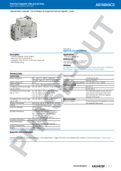
1P HA SE -O U TManual Motor Controller / Circuit Breaker for Equipment thermal-magnetic, 2 polesSee below:Approvals and Compliances Description- Thermal-magnetic circuit breaker - High short circuit performance- Availability of AC and DC in the same frame size - DIN-Rail MountingApplications - Industrial appliancesReferences Last order possibility: 31.08.2018Last delivery date: 30.09.2018Weblinkspdf datasheet , html-datasheet , General Product Information , Distributor-Stock-Check , Detailed request for product , Product NewsT echnical DataGeneral data Rated Voltage AC IEC : 420 V Y / 240 V; 50/60 Hz ␣UL/CSA : 480 V Y / 277 V; 50/60 Hz Rated Voltage DC 65 VRated current0.5 - 52 A , see approbationsConditional short circuit capa-city IEC 60934Icn: AC 420 V / DC 65 V: 5 kA (no fuse)Conditional short circuit capa-city UL 1077Inc: AC 480 V: 10 kA (with fuse class H/J, 4x rated current (min. 15 A)) Icn: AC 480 V: 5 kA (no fuse) Icn: DC 65 V: 2 kA (no fuse)Conditional short circuit capa-city UL 508Icn: AC 480 V: 5 kA (no fuse) Degree of Protection from front side IP 40 acc. to IEC 60529Lifetime 1 x Ir 6000 switching cycles Dielectric Strength 50 Hz: > 2 kVImpulse 1.2/50 μsVibration Resistance ± 0.75 mm @ 5 - 60 Hzacc. to IEC 60068-2-6, test Fc 10 G @ 60 - 500 Hzacc. to IEC 60068-2-6, test FcInsulation Resistance 250/440 VAC > 5 M ΩShock Resistance 30 G / 18 msacc. to IEC 60068-2-27, test EaAmbient temperature -10 °C to 55 °C Weight 100 - 130 gTripping TypePositively trip freeActuation Type Manual ON/OFFPermissible wire cross section 1.5 - 25 mm² / 16 - 4 AWG Switched neutral Rated Voltage AC 277 V Rated current AC/DC 65 A Function The switched neutral closes with ma-nual closure of the poles and opensautomatically with thermal magnetic tripping of the poles.Add-on modules Add-on modules Technical data for the additional modulesee separate data sheetApprovals and CompliancesDetailed information on product approvals, code requirements, usage instructions and detailed test conditions can be looked up in Details about Approvals2P HA SE -O U TApprovalsThe approval mark is used by the testing authorities to certify compliance with the safety requirements placed on electronic products. Approval Reference T ype: AS168XApproval LogoCertificates Certification Body DescriptionVDE Approvals VDEVDE Certificate Number: 40005743UL Approvals UL UL File Number: E216629 / E71572UL ApprovalsULUL File Number: E216629 / E71572Product standardsProduct standards that are referencedOrganizationDesignStandardDescriptionDesigned according to IEC 60934Circuit-breakers for equipment (CBE)Designed according to UL508, UL1077Standard for Supplementary Protectors for Use in Electrical Equipment Designed according to UL 508Standard for Industrial Control Equipment Designed according toCSA C22.2Supplementary Protectors Application standardsApplication standards where the product can be usedOrganizationDesignStandardDescriptionDesigned for applications acc.IEC/UL 60950IEC 60950-1 includes the basic requirements for the safety of information technologyequipment.CompliancesThe product complies with following Guide LinesIdentificationDetailsInitiatorDescriptionCE declaration of conformitySCHURTER AG The CE marking declares that the product complies with the applicable requirements laid down in the harmonisation of Community legislation onits affixing in accordance with EU Regulation 765/2008.RoHSSCHURTER AGEU Directive RoHS 2011/65/EUChina RoHS SCHURTER AG The law SJ / T 11363-2006 (China RoHS) has been in force since 1 March2007. It is similar to the EU directive RoHS.REACHSCHURTER AGOn 1 June 2007, Regulation (EC) No 1907/2006 on the Registration, Evaluation, Authorization and Restriction of Chemicals 1 (abbreviated as "REACH") entered into force.PDimension [mm]AS168X 2 poleA) 35 mm DIN rail EN 50022B) Max. torqueWire crosssection Max. torque1.5 ... 10 mm22.5 Nm16 ... 25 mm2 3.1 NmAWG #16 ... 8 20 ... 22 lb–inAWG #6 ... 4 26 ... 28 lb–inAS168X 2 pole and switched neutral poleA) 35 mm DIN rail EN 50022B) Max. torqueWire crosssection Max. torque1.5 ... 10 mm22.5 Nm16 ... 25 mm2 3.1 NmAWG #16 ... 8 20 ... 22 lb–inAWG #6 ... 4 26 ... 28 lb–in34PHS-U Diagrams AS168X-CB1...AS168X-CB1...NAS168X-CB1... / AS168X-ACBH1AS168X-CB1... / AS168X-ACBH2AS168X-CB1... / AS168X-ACBS1AS168X-CB1... / AS168X-ACBS2AS168X-CB1... / AS168X-ACBA5P HA SE-U Effect of ambient temperatureAC-breaker are calibrated for an ambient temperature of +40°C, DC-breakers for +23°C. To determine the rated current for a lower or6P HA SE -O U TAmpere-HorsepowerHorsepower(FLA & LRC Ratings Apply where no HP Rating is given)Nominal Circuit Voltage, VACAS168X-CBMotor Nameplate110-120200208220-240265277380-415440-480Rated Current (See Note #1)FLA Rating Starting/LRC Rating 2 pole 1 pole0.5A 0.5A 1A 1A 1.5A 1.5A 2A 2A 3A 3A 4A 4A 5A 5A 6A 6A 7A 7A 8A 8A 9A 9A 10A 10A 12A 12A 13A 13A 15A 15A 16A 16A 18A 18A 20A 20A 23A 23A 25A 25A 27A 27A 30A30AAS168X-CB Nominal Circuit Voltage, VAC110-120200208220-240380-415440-480Rated Current(See Note #1)Note #1: For AC motor circuit nameplate FLA loads, AC general-use loades, AC resistance loadsFLA Starting/ 3 pole 0.5A 0.5A 1A 1A 1.5A 1.5A 1/22A 2A 3/43A 3A 1 1/24A 4A 25A 5A 36A 6A 37A 7A 38A 8A 59A 9A 510A 10A 512A 12A 7 1/213A 13A 7 1/215A 15A 1016A 16A 1018A 18A 1020A 20A 1023A 23A 1525A 25A 1527A 27A 2030A 30A20Motor NameplateHorsepower(FLA & LRC Ratings Apply where no HP Rating is given)Rating LRC Rating10A 1/212.5A 3/420A 1/2 1/2 1/2 125A 3/4 3/4 3/4 1 1/232A 1/2 1 1 1 232A 1/2 1 1 1/2 232A 3/4 1/2 1/2 2 346A 3/4 2 2 2 346A 1 2 2 2 346A 1 2 2 3 563.5A 1 1/2 3 3 3 563.5A 1 1/2 3 3 3 581A 2 3 3 3 7 1/281A 2 3 3 5 7 1/281A 2 5 5 5 1081A 3 5 5 5 10116A 3 5 5 7 1/2 10116A 3 5 7 1/2 7 1/2 10145A 3 7 1/2 7 1/2 7 1/2 15145A3 7 1/2 7 1/2 10 153°6° 1/109° 1/10 1/10 1/10 1/612A 1/8 1/6 1/6 1/418A 1/10 1/6 1/6 1/4 1/4 1/3 1/3 1/224A 1/8 1/4 1/3 1/3 1/3 1/3 1/2 130A 1/6 1/3 1/3 1/2 1/2 1/2 3/4 1 1/236A 1/4 1/2 1/2 1/2 3/4 3/4 1 242A 1/4 1/2 1/2 3/4 1 1 1 1/2 248A 1/3 3/4 3/4 1 1 1 2 254A 1/3 3/4 1 1 1 1 1/2 2 360A 1/2 1 1 1 1/2 1 1/2 2 2 372A 1/2 1 1/2 1 1/2 2 2 2 3 378A 1/2 1 1/2 1 1/2 2 2 2 3 390A 3/4 2 2 2 3 3 3 596A 1 2 2 2 3 3 3 5108A 1 2 2 3 3 3 5 5120A 1 1/2 3 3 3 3 3 5 5138A 1 1/2 3 3 3 3 3 5 7 1/2150A 2 3 3 3 5 5 5 7 1/2162A 2 3 3 3 5 5 7 1/2 10180A2 3 3 5 5 5 7 1/2107P H-Time-Current-Curves Version F / Magnetic 3-5 xl nT i m e i n S e c o n d snMultiple of Rated Current InReference Temperature +23°Version G / Magnetic 6-10 xl nT i m e i n S e c o n d snMultiple of Rated Current InReference Temperature +23°Version H / Magnetic 12-20 xl nT i m e i n S e c o n d sMultiple of Rated Current InReference Temperature +23°Config. CodeAS168X-CB 1DG |200|N |The characters are placeholders for the correspondingly keys of selections from the key tables.AS168X-CB 1 DG |200|N | = Number of Poles8-O AS168X-CB 1 DG 200N = Tripping characteristicsAS168X-CB |1|DG | 200 |N | = Rated currentAS168X-CB |1|DG |200| N | = Switched neutralVariants9P HA SE -OPackaging Unit 1 PcsThe specifications, descriptions and illustrations indicated in this document are based on currentinformation. All content is subject to modifications and amendments. Information furnished is believed 19.02.2018。
迪龙 500W48V纯正弦波逆变器使用说明书

500W48V纯正弦波逆变器使用说明书一,前言:本逆变器使用本公司智能IC控制,其线路已申请专利,具有非常完善的保护功能(包括过载保护,过流保护,高温保护,短路保护,反接保护,电池高.低压保护,设有内置式保险丝等等),指示功能。
采用优质的双面线路板及零器件,保证产品高质量,高性能。
本机的输出波形为纯正弦波,可以适用于任何负载,过载保护,过流保护,短路保护,保护后自动延时10秒启动。
本机的体积非常小巧,便于携带。
二:使用方法将足够功率的输入电源接上逆变器,注意电源电压要在规定范围内,连接的电源线要有足够的承载电流能力,并且尽量短,打开逆变器的电源开关,输出负载在开机前或开机后接入均可(我公司产品配有符合标准的电源线)。
三,输入电源要求:z输入电源电压必须在逆变器规定的电压范围内。
z输入电源必须能够提供足够的电流,其具体算法约为输出功率/输入电压/0.8=输出电流,例如:带一个500W的负载,输入48V,则输入电流=500/48/0.8=13(A)。
z输入电源线必须要与逆变器连接牢固,并且要有足够的承载能力。
如果电流为13A,电源线的截面面积应尽量大于6.5平方毫米。
四,技术参数:型号PNI-S50048A5额定功率500W峰值功率 1000W输入电压40VDC-61VDC输出电压220VAC±5%输出频率50Hz输出波形纯正弦波工作效率>84%五,保护:输入反接保护 自动恢复输入保险丝 20A输入电压保护<40V 和 >62V低输入电压报警44V±1V输出过载且<700W保护时间30秒输出短路保护时间2~3秒温度保护 >70℃六,状态指示:正常输出 两个绿灯亮电池低压报警 输入绿灯闪电池低压关机输入红灯亮输出过载 输出绿灯闪,30秒后,关机。
重载保护 输出红灯亮,2~3秒后,关机,10秒钟后重启温度保护 输入黄灯亮七,工作环境:温度 -20~40摄氏度八,物理特征:尺寸 240 x 166 x 62mm重量 2kg九,注意事项:z本逆变器只能接小于其所规定最大功率的负载。
海门48V说明书

第 8 页/共 14 页
□ □ □ □ HM2436-275 HM3648-275 HM3648-350 HM3648-650 使用说明书
电阻 250/5W
电瓶
极性保护二极管 控制线路保险丝
钥匙开关
主接触器 主接触器线圈
P4 P8 P3 P7 P2 P6 P1 P5
BVM
B+ A2
连接至电机的励磁绕组
连接至电机的A2
图 7 控制器大电流接线端示意图
电缆用 M8 螺栓与母线相连接 固定螺栓时 应使用两个板手相对旋转 以防止拧弯母线和内部连接 产生附加应力 注意 应根据系统负荷选用 16 25mm2 以上电缆线
标准接线
图 8-图 10 所示为用于串励电机的基本接线
型号 HM2436-275 HM3648-275 HM3648-350 HM3648-650
电瓶电压 V 24-36 36-48 36-48 36-48
电流限制 A 275 275 350 650
1 小时电流 A 125 125 150 225
欠电压点 V 18 24 24 24
外形及安装尺寸
8孔插座
永磁 电机控制器 他励电机控制器 适用于电动三轮车 高尔夫球车 电动游览 车 场地电动服务车辆及电动叉车的行走控制
本手册主要介绍海门公司现有串励电机控制器产品的技术特性 安装使用方法及 维修方面的知识
用户在使用海门公司的串励控制器前 请详细阅读本手册 这会帮助您正确地安 装和使用控制器
如在使用过程中遇到困难 请与我公司联系 联系方式如下
安装 ............................................................................................................................. 6 接线 ............................................................................................................................. 6 标准接线 ..................................................................................................................... 8 安装后检查 ................................................................................................................11 维护及故障诊断 ............................................................................................................... 12 安全性 ............................................................................................................................... 12 清洁 ................................................................................................................................... 12 故障诊断 ........................................................................................................................... 12
艾默生48V电源

QUICRUN 电动车电机说明书

150W 33A 24.0*36.5
2.30电越/卡车/大脚车
QUICRUN-3656-3800KV 30404100 3800KV 2-3S 0.0055 2.3A
420W 110A 36.0*56.0
3.17*16
4
232 1:10 电房/电越/卡车/大脚车
齿比选择
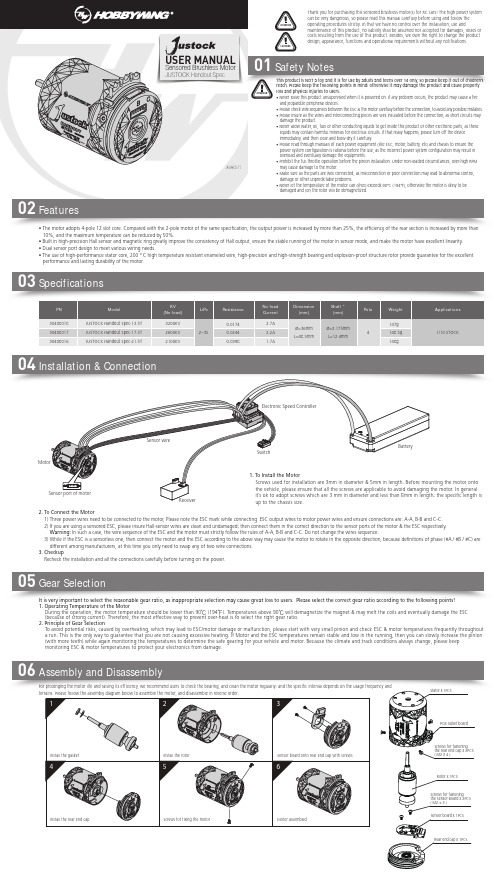
齿比的合理选择非常重要,不合适的齿比可能会给您带来重大损失。请遵守以下要点来正确选择齿比! 1.电机的工作温度
电机在工作时,温度应低于90°C(194°F);温度高于90°C时,将会使电机转子磁性减弱,且线圈可能出现局部烧熔短路现象,产生大电流而损坏电调。选择合适的齿比可以有效防止 电机过热。 2.齿比选择原则 为防止电机过热引发潜在危险而导致电调和电机损坏,请从一个最少齿数的电机小齿进行齿比配置,并随时检查电机温度,这是唯一能确保电机不过热的方法。车子在行驶途中,如果电 机及电调温度一直处于稳定的低温范围内,您可以试着使用齿数较多的小齿,并密切监测电机温度,以确定更改后的齿比是否适合您的模型车、当地气候及赛道条件(请注意气候及赛道 条件不是恒定不变的,而是经常会发生变化,所以频繁地监测电调及电机的温度是一项重要的日常操作,它可以确保您的电子设备长期稳定地工作)。
电机转子 x 1
5,装配电机转子前端间隙调整垫;
注意:由于电机转子在制造过程中会有一定的公差, 故每款电机间隙调整垫数量可能会不一致。
6,装配金属面壳; 注意:螺丝孔位对准后再装配
请访问好盈科技网站: /cn/index.asp 查阅高分辨率装配图。
7,装配金属面壳4颗固定螺丝;
误的动力搭配导致电机超载而损坏。 • 齿轮未安装前,禁止全油门操作。无负载情况下高速运转可能会损坏电机。 • 请务必仔细连接好各部件,若连接不良,遥控模型车可能无法正常控制,或出现部件损
中文B200说明书
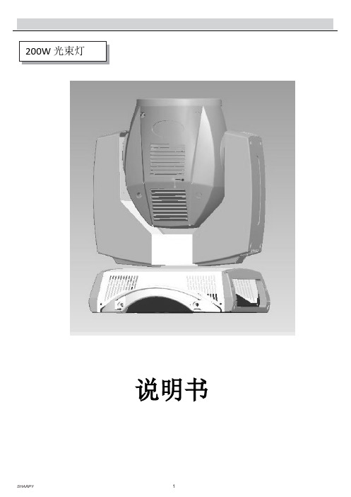
200W 光束灯说明书简要介绍Sharpy,200W,重量仅17.5公斤,可以发出一种平行光束,类似激光束,这是一种令人难以置信的输出。
Sharpy 拥有开创性的白光纯度。
它提供了14种不同的颜色和17图案,让你快速改变光束形状,展现出一个壮观的半空效果。
Sharpy重量轻,功率小,紧跟时尚外形设计,但是功能更强大,亮度更高,可以轻易地安装在任何地方-在各种移动舞台,电视活动,展示厅或会议室。
电源110 - 240V ,50/60HZ电子整流器或者传统镇流器。
可选。
灯源YODA 5R输出灯功率:200W色温:8500 K -平均寿命:2,000 h光学镜头3个光学镜头组组合电子聚焦光输出为20米(65英尺):59760LUX色盘带有14种颜色+白光。
半色效果图案盘及效果17个固定图案+白光高速抖动8面旋转棱镜速度可调频闪效果机械调光及雾通道控制16 DMX 512控制红色LED 点阵显示。
X/Y水平垂直:16 bit 水平: 540° - 垂直:250°DMX信号连接:3脚输出重量17.5 kgs结构铝压铸塑料。
快速锁显示板菜单:通道表:ChannelFunction DMXvalue Feature Note16 Bit1颜色Colorwheel000-005 White+red005-009 red009-013 Red+orange013-018 orange018-022 Orange+aquamarine022-026 aquamarine026-030 Aquamarine+green030-035 green035-039 Green+light green039-043 Light green043-047 Light green+lavender047-052 Lavender052-056 Lavender+pink056-060 Pink060-064 Pink+yellow064-069 Yellow069-073 Yellow+meganta073-077 Meganta077-082 Magenta+cyan082-086 Cyan086-090 Cyan+cto260090-094 Cto260094-099 Cto260+cto190099-103 Cto190103-107 Cto190+ctb8000107-111 Ctb8000111-116 Ctb8000+blue116-120 Blue120-124 Blue+white124-128 Slow roation128-255 Fast rotation(160 rpm)000-003 closed004 Slow strobe(1 flash/sec)103 Fast strobe(12 flash/sec)2频闪Stop/strobe104-107 open108 Slow pulsation108-207 Fast pulsation208-212 open213-225 Random slow strobe226-238 Random medium strobe239-251 Random medium strobe252-255open3调光Dimmer 000-2554图案Static gobochange000-003 White003-071 Gobo1-gobo17071-072 Fast rotation072-113 Slow rotation114-117 Stop118 Slow rotation159 Fast rotation160-166 Gogo2shake,slow-fast speed167-172 Gogo3 shake,slow-fast speed173-179 Gogo4 shake,slow-fast speed180-185 Gogo5 shake,slow-fast speed186-191 Gogo6 shake,slow-fast speed192-198 Gogo7 shake,slow-fast speed199-204 Gog8 shake,slow-fast speed205-211 Gogo9 shake,slow-fast speed212-217 Gogo10 shake,slow-fast speed218-223 Gogo11 shake,slow-fast speed224-230 Gogo12 shake,slow-fast speed231-236 Gogo13 shake,slow-fast speed237-243 Gogo14 shake,slow-fast speed244-249 Gogo15 shake,slow-fast speed250-255 Gogo16 shake,slow-fast speed5棱镜Prisminsertion000-127 Prism excluded128-255 Prism inserted6 棱镜自转Prismrotation000 Position 0°021 Position 90°042 Position 180°063 Position 270°084 Position 360°105 Position 450°127 Position 540°128-190 Fast rotation(120rpm)191-192 Stop192-193 Slow rotation(3rpm)193-255 Fast rotation(120rpm)7功能Function000-100 unused101-128 Beam function128-255 Unused8 雾化frost000-128 Frost excluded070-079 Frost inserted9调焦focus 000-255 水平Xpan 000-2551011 水平微调Pan fine 000-25512 垂直 YTilt 000-12813 垂直微调Tilt fine 000-25514 X/Y 速度speed 000-255Fast to slow15 复位Reset 000-128 Unused range 128-255 Rest all16 开关泡Lampcontrol 000-025 Unused range 026-100 Lamp off 101-255 Lamp on。
SEIKO C-7使用说明书
7B24使用说明书应对世界3个地区的太阳能电波 日本、中国、美国※ 选购时的金属表带,可在经销店或本公司售后服务中心进行调整。
在其他商店进行调整可能会收费,或不能得到服务。
承蒙选购本公司的产品,谨在此表示衷心的感谢。
使用之前,请熟读本说明书,并正确地使用手表。
本说明书请安放在随手能看到的地方,以便必要时参阅。
BSC7B24-A 210923123456781. 使用产品时的注意事项..............................................4 特点......................................................................................6 各部件的名称和主要功能.........................................8 关于B 按钮 ....................................................................10 关于表把..........................................................................112. 使用之前..........................................................................12 确认能源余量...........................................................12 确认时间和日期......................................................133. 接收电波,以对准时间和日期。
........................14 接收电波的机制......................................................14 自动接收和强制接收.. (15) 接收环境.....................................................................16 大致的接收范围:日本(JJY) .......................16 大致的接收范围:中国(BPC) ......................17 大致的接收范围:美国(WWVB) .................18 为了容易接收电波.................................................19 接收困难的环境......................................................20 确认是否能够接收......................................................22 接收结果的显示......................................................224. 什么是时差修改功能是什么..................................24 时差修改功能的特点............................................24 关于时差修改功能的问答..................................25 设定时差(选择接收局) .........................................26 世界主要地区时差一览表 (28)5. 关于充电充电................................................................30 充电的方法................................................................30 充电大致所需时间.................................................31 关于能源..........................................................................32 能源短缺预告功能.................................................32 节能功能.....................................................................336. 注意事项..........................................................................34 维修...............................................................................34 性能与型号................................................................35 防水性能.....................................................................36 抗磁性能(磁性的影响) ....................................40 表带...............................................................................42 特殊表扣表带的使用方法..................................44 关于Lumibrite(智慧光能) ..............................49 电源. (50) 保证...............................................................................52 售后服务.....................................................................547. 强制接收的方法(以手动方式接收电波) ...............56 不能接收电波时...........................................................58 手动对准时间的方法............................................58 手动对准日期的方法............................................60 关于标准位置................................................................62 四周发出磁性的物体............................................63 标准位置的对准方法.................................................64 对准日期的标准位置............................................64 以手动对准时分针的标准位置........................66 出现这样的问题时......................................................68 万一出现异常动作时.................................................76 系统的复位................................................................768. 产品规格.. (80)※ 请立刻与经销店或本公司售后服务中心联系。
罗克韦尔 安装数据交流(48V)输入模块. 数据表

AC (48V) Input Module Cat. No. 1771-IND1Installation DataThis document provides information on:important pre–installation considerations power supply requirements initial handling installing the moduleusing the indicators for troubleshooting module specificationsThis module must be used with a 1771 Series B I/O chassis. If you are using a 1771–ASB remote I/O adapter you may use any combination of I/O modules. Otherwise, make sure no other input module or single card block transfer module is placed in the same I/O group.This module contains input filtering to limit the effects of voltagetransients caused by contact bounce and/or radiated electrical noise. The delay due to filtering is listed in the Specifications section.Your module receives its power through the 1771 I/O chassis backplane from the chassis power supply. The module requires 250mA from the output of this supply. Add this to the requirements of all other modules in the I/O chassis to prevent overloading the chassis backplane and/or backplane power supply.To The InstallerPre-installation ConsiderationsPower Requirements2The ac input module is shipped in a static–shielded bag to guard against electrostatic discharge damage. Observe the following precautions when handling the module.Initial Handling3Electrostatic Discharge DamageATTENTION: Under some conditions, electrostatic discharge can degrade performance or damage the module. Observe the following precautions to guard against electrostatic damage.Wear an approved wrist strap grounding device, or touch a grounded object to discharge yourself before handling the module.Do not touch the backplane connector or connector pins.If you configure or replace internal components, do not touch other circuit components inside the module. If available, use a static–free work station.When not in use, keep the module in a static–shielded bag.In this section we tell you how to set the fault mode selection plug, key your I/O chassis, install your module and make your wiring connections.Setting the Fault ModeYou may select one of two input–failure configurations (last state or reset)by positioning a configuration plug on the top edge of the printed circuit board. This configuration plug is independent of the last state switch on the I/O chassis backplane.To set the fault mode selection, proceed as follows:1.Locate the fault mode selection plug at the top edge of the module circuit board (Figure 1).ing your finger, slide the plug off the 2 posts.,3.Carefully position the plug on 2 of the 3 posts that correspond to your requirement.Figure 1Fault Mode Selection Plug10425-IInstalling Your Module4Keying Your I/O ChassisUse the plastic keying bands, shipped with each I/O chassis, to key the I/O slots to accept only this type of module.The module circuit board is slotted in two places on the rear edge. The position of the keying bands on the backplane connector must correspond to these slots to allow insertion of the module. You can key any connector in an I/O chassis to receive this module except for the left–most connector reserved for adapter or processor modules. Place keying bands between the following numbers labeled on the backplane connector:between 4 and 6between 8 and 10You can change the position of these keys if system redesign and rewiring makes insertion of a different module necessary.Installing the Input ModuleTo install the ac input module in your 1771 I/O chassis, follow the steps listed below.ATTENTION: Remove power from the 1771 I/O chassis backplane and wiring arm before removing or installing an I/O module.Failure to remove power from the backplane or wiring arm could cause module damage, degradation of performance, or injury.Failure to remove power from the backplane could cause injury or equipment damage due to possible unexpected operation.1.Turn off power to the I/O chassis.2.Place the module in the plastic tracks on the top and bottom of the slot that guides the module into position.3.Do not force the module into its backplane connector. Apply firm,even pressure on the module to seat it properly.4.Snap the chassis latch over the top of the module to secure its position.5.Connect the wiring arm to the module.6.Make wiring connections to the field wiring arm as indicated in .5Connecting Wiring to the Input ModuleConnections to the input module are made to the 21 terminal field wiring arm (cat. no. 1771–WH) shipped with the module. Attach the wiring arm to the pivot bar on the bottom of the I/O chassis. The wiring arm pivots upward and connects with the module so you can install or remove the module without disconnecting the wires.Connect one terminal of your 2–wire input devices to terminals 5 through 20 (Figure 2).Figure 2Connection DiagramNot used Not used Not used Not usedL2Input 0Input 1Input 2Input 3Input 4Input 5Input 6Input 7Input 8Input 9Input 10Input 11Input 12Input 13Input 14Input 1510426-I1XY001XY011XY021XY031XY041XY051XY061XY071XY101XY111XY121XY131XY141XY151XY161XY17Input Assignment I/O Program AddressWhere:X = Rack # (1, 2, ...)Y = Module Group (0-7)6Connect terminal 21 to the L2 (low) ac return. Terminals A through D are not used. (Note: In ungrounded applications, connect terminal 1 to L1 to balance the line.) Connect the L1 (high) ac line to the other terminal of your input devices. Use stranded 14 or 16 gauge wire to minimize the voltage drop over long cable distances.Important: You can use an AC (10–60V) Output Module (cat. no.1771–OND) to directly drive terminals on an AC (48V) Input Module (cat. no. 1771–IND1) (Figure 3). You can also use a 1771–ON Output module to drive an AC (48V) Input Module (cat. no. 1771–IND1) but you must connect a 470 ohm, 3W resistor or a 4.7 ufd, 100V ac capacitor between the output terminal and L2 (common) as shown in . Use the same ac power source to power both modules to ensure proper phasing and prevent module damage.Figure 3Driving a 1771-IND Module with a 1771-OND ModuleL2AC (10-60V)Output Module(Cat. No. 1771-OND)AC (48V)Input Module(Cat. No. 1771-IND1)L210427-I7Figure 4Driving an Input with an Output(Cat. No. 1771-ON)L1L2AC (24V)Output Module AC (48V)Input Module (Cat. No. 1771-IND1)L210428-IThe front panel of your module contains one green, module active LED,and 16 red status LED indicators (). The 1771–IND1 performs diagnostics in a handshaking mode when first powered up. Uponsuccessful completion of the diagnostics, the green module active indicator lights. It turns off if a fault occurs in the data paths or the opto–isolators.The red status indicators are provided for system logic side indication of individual inputs. When a red LED lights, voltage is present on the terminal. The module transfers this information to the backplane for the processor to read.Interpreting the Status Indicators8Figure 5Status IndicatorsACTIVE00010203040506071011121314151617Module Active Indicator (green)00 to 17 Status Indicators (red)10429-IUse the table below to help you interpret the status indicators and to isolate module or system faults.TroubleshootingSpecifications910With offices in major cities worldwideWORLDHEADQUARTERS Allen-Bradley1201 South Second Street Milwaukee, WI 53204 USA Tel: (1) 414 382-2000Telex: 43 11 016FAX: (1) 414 382-4444EUROPE/MIDDLE EAST/AFRICA HEADQUARTERSAllen-Bradley Europe B.V .Amsterdamseweg 151422 AC Uithoorn The Netherlands Tel: (31) 2975/43500Telex: (844) 18042FAX: (31) 2975/60222ASIA/PACIFIC HEADQUARTERSAllen-Bradley (Hong Kong)LimitedRoom 1006, Block B, Sea View Estate 28 Watson Road Hong KongTel: (852) 887-4788Telex: (780) 64347FAX: (852) 510-9436CANADAHEADQUARTERS Allen-Bradley Canada Limited135 Dundas StreetCambridge, Ontario N1R 5X1CanadaTel: (1) 519 623-1810FAX: (1) 519 623-8930LATIN AMERICA HEADQUARTERS Allen-Bradley1201 South Second Street Milwaukee, WI 53204 USA Tel: (1) 414 382-2000Telex: 43 11 016FAX: (1) 414 382-2400As a subsidiary of Rockwell International, one of the world’s largest technologycompanies — Allen-Bradley meets today’s challenges of industrial automation with over 85 years of practical plant-floor experience. More than 11,000 employees throughout the world design, manufacture and apply a wide range of control and automation products and supporting services to help our customers continuously improve quality, productivity and time to market. These products and services not only control individual machines but integrate the manufacturing process, while providing access to vital plant floor data that can be used to support decision-making throughout the enterprise.Publication 1771–2.205 – March 1991P/N 955109–83Printed in USA。
Tridonic LMI G2 48V 350-700mA 3-20V DIM Slim数据表说明书

Product description• DALI dimmable• Up to 89 % efficiency• Output voltage range 3 – 20 V• Adjustable output current between 350 and 700 mA• Pure AM dimming down to 5 %• Max. tc point temperature 110 °C• 5-year guaranteeHousing properties• Pure PCB for built-in application• Suitable for class III applicationsInterfaces• DALI-2 – DT 6• Terminal blocks: 0° push terminalsFunctions• Adjustable output current• Protective features (overtemperature, short-circuit, no-load)Benefits• Application-oriented operating window• Small dimensions for miniaturization of luminaires• No additional wires needed; DALI signals via the powerlineÈStandards, page 3LMI G2 48V 350–700mA 3–20V DIM Slim DimmingSpecific technical dataTypeOutput current Min. forward voltageMax. forward voltageMax. output power (at 48 V, full load)Typ. power consumption (at 48 V, full load)Typ. current consumption (at 48 V, full load)LMI G2 48V 350-700mA 3-20V DIM Slim350 mA 3 V 20 V 7 W 8.2 W 170 mA 400 mA 3 V 20 V 8 W 9.2 W 192 mA 450 mA3 V 20 V 9 W 10.3 W 214 mA 500 mA 3 V 20 V 10 W 11.4 W 243 mA 550 mA 3 V 20 V 11 W 12.4 W 257 mA 600 mA 3 V 20 V 12 W 13.4 W 279 mA 650 mA 3 V 20 V 13 W 14.5 W 302 mA 700 mA3 V20 V14 W15.7 W328 mA1Valid at 100 % dimming level.2Depending on the selected output current.Technical dataDC voltage input 48 VDC voltage range 46 – 50 V Mains frequency 0 Hz Typ. current (full load)137 – 328 mA Max. input power 16 W Typ. efficiency (full load)1289 %Typ. input current in no-load operation 8 mA Typ. input power in no-load operation< 0.4 W Time to light (full load)< 0.6 s Hold on time at power failure < 5 ms Output current tolerance 1± 5 %Output current tolerance (at min. dimming level)± 10 %Max. peak output current ≤ output current + 30 %Output LF current ripplesame as LF ripple on 48 V bus Max. output voltage (no-load voltage)48 V Dimming range 5 – 100 %ESD classification Severity level 2Max. tc point temperature 110 °CDimensions L x W x H125 x 14.8 x 12.5 mmLMI G2 48V 350–700mA 3–20V DIM Slim DimmingOrdering dataTypeArticle Packaging Packaging Packaging Weight per pc.We recommend using following LCU DC power supply together with this LMI LED Driver:TypeArticle number PackagingPackaging Weight per pc.3. Installation / wiring3.1 Circuit diagramLED module/LED Driver/supplywire preparation:3.2 Wiring type and cross sectionSolid or stranded wire with a cross section of 0.2 – 0.75 mm².Strip 6 – 7 mm of insulation from the cables to ensure perfect operation of terminals.1. StandardsEN 61347-1 EN 61347-2-13 EN 62384EN 62386-101 (according to DALI standard V2)EN 62386-102EN 62386-2072. Thermal details and life-time2.1 Expected life-timeLife-time is limited by DC power supply.Max. tp point temperature must not be exceeded.4. Electrical values4.1 Operating window051015040050060070080090010020030010002520Output current [mA]O u t p u t v o l t a g e [V ]8081828384858640607080905010090878988Load [%]E c i e n c y [%]100 % load corresponds to the max. output power (full load) according to the table on page 2.mA mAmA 4.2 Efficiency vs load3.5 EOS/ESD safety guidelinesThe device / module contains components that are sensitive to electrostatic discharge and may only be installed in the factory and on site if appropriate EOS/ESD protection measures have been taken. No special measures need be taken for devices/modules with enclosed casings (contact with the pc board not possible), just normal installation practice.For further information for EOS/ESD safety guidlines and the ESD classification please refer to the brochure entitled /esd-protection.3.4 LED module hot plug-inHot plug-in is not supported due to residual output voltage of > 0 V.The LED Driver will not be damaged but there is a risk of destroying the LED module.Saving the DALI parameters is not guaranteed.3.3 Wiring guidelines• The 48 V cables should be run separately from the mains connections and mains cables to ensure good EMC conditions.• The 48 V DC output wiring should be kept as short as possible to ensure good EMC. Tridonic did successfully EMC test with more than 30 m on grounded metal housings.• For plastic housing reduce the cable length if the EMC get worse.• The max. cable length, including track light, is limited only by voltage drop: The last LMI 48V in the track light must still supplied with minimum 46 V. More details in the voltage drop application note!• Secondary switching is not permitted.• To avoid the damage of the Driver, the wiring must be protected against short circuits to earth (sharp edged metal parts, metal cable clips, louver, etc.).5. Interfaces / communication5.1 Control inputThe device is controlled via DC power supply.5.2 switchDIMThe device is controlled via DC power supply.4.3 DimmingDimming range 5 to 100 % of nominal current Digital control with:Programmable parameter: Minimum dimming level Maximum dimming levelDefault minimum = depending on nominal current level Default maximum = 100 %Dimming curve is adapted to the eye sensitiveness.Dimming is realized by amplitude dimming.2252552001751501251007550250100908070605040302010Dimming characteristics Digital dimming value Relative lighting level %Dimming characteristics as seen by the human eye4.4 Dimming characteristics5.3 Short-circuit behaviourThe LED Driver will not be damaged. In case of a short-circuit at the LEDoutput the LED output is switched off. As soon as the short circuit removed the device has to be restarted via mains on / off DC power supply or DALI on / off command.5.4 No-load operationThe LED Driver will not be damaged in no-load operation. The output will be deactivated and is therefore free of voltage (after a short period of time).As soon as the LED is connected the device has to be restarted via mains on / off DC power supply or DALI on / off command.5.5 Overload protectionIf the output voltage range is exceeded the LED Driver turns off the LED output. After restart of the DC power supply or DALI on / off the LED Driver output will be activated again.5.6 Overtemperature protectionThe LED Driver is protected against temporary thermal overheating. If the temperature limit is exceeded the LED Driver will turn off and after cool down phase automatically restart. The temperature protection is activated approx. +5 °C above tc max (see page 2).7.1 Conditions of use and storage Humidity: 5 % up to max. 85 %, not condensed(max. 56 days/year at 85 %)Storage temperature:-40 °C up to max. +80 °CThe LED Drivers have to be acclimatised to the specified temperature range (ta range of DC power supply) before they can be operated.7. Miscellaneous6. Functions6.2 Adjustable currentThe output current of the LED Driver can be adjusted in a certain range. DALI:Adjustment is done by masterCONFIGURATOR at DC power supply (see masterCONFIGURATOR documentation).6.1 Storage of programmed parametersThe programming is only saved after a restart of the device.For immediate storage, a manual DALI save command must be send.7.2 Additional informationAdditional technical information at → Technical Data Guarantee conditions at → ServicesLife-time declarations are informative and represent no warranty claim.No warranty if device was opened.。
新维-AMDS B 系列电动机保护器使用手册

第十七章 AMDS-□/B系列电动机保护器17.1、AMDS-□/B 系列电动机保护器AMDS-□/B 0 □ □1: 1常开、常闭继电器触点(AC 250V/10A(阻性负载)、DC 30V/10A);2: 2常开、常闭继电器触点(AC 220V/5A(阻性负载)、DC 30V/5A);0:接地、短路、缺相、堵转、电流不平衡、过载;1:接地、短路、缺相、堵转、电流不平衡、过载、零序;无通讯接口、无4-20mA输出、无运行状态输出;4 位LED显示3相及零序电流、故障代码、保护参数;保护器额定电流(A),是 0.5、1、2、5、10、20、50、100、150、200 之一;AMDS-□/B 系列保护器主单元 AMDS-□/B 系列电流检测单元及电缆主要特点:单片机为核心,数字设定、数字显示,保护功能完备、保护性能可靠。
按键设置保护参数,4位LED数码管显示三相及零序电流、故障代码、保护参数;主单元小体积柜内导轨安装;基本保护功能:接地、短路、缺相、堵转、电流不平衡、过载;可选保护功能:零序;适用范围:额定电压不高于1140V,频率为50Hz、60Hz的三相交流电动机;工作电压:AC 85V — 265V、DC 85V — 265V;功率消耗:小于 2W;采集精度:1.0;环境温度:- 20℃ — 50℃;连接电缆:连接主单元与电流检测单元,6×0.3mm²×2.2 m双绞屏蔽电缆。
17.2、AMDS-□/B 系列电动机保护器技术数据(型号省略了AMDS-□/B0□□中的/B0□□)电动机保护器型号 AMDS-0.5 AMDS-1 AMDS-2AMDS-5AMDS-10AMDS-20AMDS-50 AMDS-100 AMDS-150AMDS-200最大设定电流(A) 0.55 1.1 2.3 5.5 11 23 55 110 165 220 最小设定电流(A) 0.1 0.2 0.4 1 2 4 10 20 30 40 电动机最大功率(KW) 0.22 0.4 1.1 2.2 4 11 22 45 75 110 电动机最小功率(KW) 0.055 0.11 0.22 0.55 1.1 2.2 5.5 11 18.5 22 电动机电源穿线孔Φ(mm)20 20 20 20 20 20 20 20 30 30 注:表中电动机的额定电压为380V,电动机因型号、极数的不同,相同功率的额定电流会有不同,选用电动机保护器时应以电动机工作电流值为准。
森森电磁气泵HJB200说明书
森森电磁气泵HJB200说明书
1、耐久性
堪长期连续使用,具优越耐久性;
2、无需润滑油
毫无滑动部件,因此不需润滑油,使排出气体干净;
3、高效率
运作是以电磁振动为基本原理,可免除滑动零件的需求面,因此节约能源,效率高;
4、轻巧有力
气泵组成是由两个电磁铁:一个在前,一个在后,为**性电磁铁。
提供完善平衡型振动,构成一个轻巧具有力的装置;
5、低噪音
当设计这个充气电路及振动部位,声音隔离是重要的;
6、空气流畅
排气稳定,振动极微;
7、维修简单
组件替换简易,如破裂膜片简单维修后便可长期使用。
8、应用范围
医疗器械(气垫床,按摩椅等);废水处理(净化槽,移动厕所,爆气机);医疗器械,如气体分析仪;印刷机械;纺织机械等等能源高效率送风机省能源。
恒星RC汽车电动机说明书
Safety Notes0102Features05Gear Selection06Assembly and Disassembly03SpecificationsIt is very important to select the reasonable gear ratio, as inappropriate selection may cause great loss to users. Please select the correct gear ratio according to the following points!1. Operating Temperature of the MotorDuring the operation, the motor temperature should be lower than 90℃ (194℉). Temperatures above 90℃ will demagnetize the magnet & may melt the coils and eventually damage the ESC (because of strong current). Therefore, the most effective way to prevent over-heat is to select the right gear ratio. 2. Principle of Gear SelectionTo avoid potential risks, caused by overheating, which may lead to ESC/motor damage or malfunction, please start with very small pinion and check ESC & motor temperatures frequently throughout a run. This is the only way to guarantee that you are not causing excessive heating. If Motor and the ESC temperatures remain stable and low in the running, then you can slowly increase the pinion (with more teeth) while again monitoring the temperatures to determine the safe gearing for your vehicle and motor. Because the climate and track conditions always change, please keep monitoring ESC & motor temperatures to protect your electronics from damage.For prolonging the motor life and raising its efficiency, we recommend users to check the bearing, and clean the motor regularly; and the specific interval depends on the usage frequency and terrains. Please follow the assembly diagram below to assemble the motor, and disassemble in reverse order.USER MANUALJUSTOCK Handout SpecSensored Brushless Motor• The motor adopts 4-pole 12 slot core. Compared with the 2-pole motor of the same specification, the output power is increased by more than 25%, the efficiency of the rear section is increased by more than 10%, and the maximum temperature can be reduced by 50%.• Built in high-precision Hall sensor and magnetic ring greatly improve the consistency of Hall output, ensure the stable running of the motor in sensor mode, and make the motor have excellent linearity.• Dual sensor port design to meet various wiring needs.• The use of high-performance stator core, 200 ° C high temperature resistant enameled wire, high-precision and high-strength bearing and explosion-proof structure rotor provide guarantee for the excellent performance and lasting durability of the motor.This product is NOT a toy and it is for use by adults and teens over 14 only, so please keep it out of children’s reach. Please keep the following points in mind; otherwise it may damage the product and cause property loss and physical injuries to users.• Never leave this product unsupervised when it is powered on. If any problem occurs, the product may cause a fire and jeopardize peripheral devices.• Please check wire sequences between the ESC & the motor carefully before the connection, to avoid any possible mistakes. damage or other unpredictable problems.• Never let the temperature of the motor can (shell) exceeds 90°C (194°F), otherwise the motor is likely to be damaged and (or) the rotor will be demagnetized.04Installation & Connection3. CheckupRecheck the installation and all the connections carefully before turning on the power.Stator x 1PCSPCB outlet boardScrews for fastening the rear end cap x 3PCS ( M2 x 4 )Rotor x 1PCSScrews for fastening the Sensor Board x 2PCS ( M2 × 3 )Sensor board x 1PCSRear end cap x 1PCS。
恒达引擎机车辆产品说明书

PARTS LIST(4)(7)(1)(2)No.DescriptionQty (1)Installation Instruction URL 1(2)Recoil starter 1(3) 6 mm flange bolt 4(4)Recoil pulley comp.1(5)12 mm flange bolt 1(6)O-Ring 1(7)Oil seal 1(8)Condenser unit1TOOLS AND SUPPLIES REQUIREDSocket (10 and 17 mm)RatchetRatchet extensionRecoil pulley holder (T/N: 075MB-HM70100)Engine oilTorque wrenchUSE AND CARE INFORMATION• Check the flange bolts periodically for the proper torque.• Do not pull the recoil starter grip while the engine is running.• If the starter grip does not return smoothly (because of dirt in the assembly), see your Honda dealer.• The recoil starter is used to start the engine when the battery is low.To operate the recoil starter:1. Turn the ignition switch to ON and engine stop switch to RUN.2. Check that the transmission is in neutral.3. Grasp the starter grip firmly, then pull it out slowly approximately 100 mm (4 in).4. Pull the grip up briskly and fully.5. After the engine starts, allow the starter grip to recoil slowly and then let go.ItemN·m kgf·m Ibf·ft 6 mm flange bolt 12 1.2912 mm flange bolt1081180TORQUE CHARTTighten all screws, bolts, and nuts to their specified torque values. Refer to the Service Manual for the torque values of the removed parts.STARTER GRIP<Right side>3. Disconnect the negative (-) cable from the battery.2. Refer to the Service Manual to remove the parts.INSTALLATIONradiator, etc. to cool before installing the accessory.NOTE:• Disconnect the negative (-) cable from the battery before installing this accessory.• The memories of the tripmeter and clock will be erased when you disconnect the battery. Reset the clock after reconnecting the battery.1. Refer to the model specific Service Manual toremove the indicated parts.<TRX500 SHOWN>4. Install the oil seal as shown. 6. Install the recoil starter as shown.7. Install the condenser unit as shown.5. Install the recoil pulley as shown. Use the special toolto hold the recoil pulley while torquing the flange bolt.• NOTE : The recoil pulley is keyed to the flywheel. Be sure to properly index the recoil pulley to the flywheel before installing the o-ring and bolt.(Reuse)<Inside the battery box>8. Connect the condenser unit harness as shown.OPERATION CHECKS AFTER INSTALLATION1. Check that the transmission is in neutral. Array2. Check that the negative (-) battery cable isdisconnected from the battery.3. Turn the ignition switch ON.4. Hold the recoil starter grip firmly and pull it vigorouslyto start the engine.5. Stop the engine. Turn the ignition switch OFF andreconnect the negative (-) battery cable securely.• Note that the above procedure is for checkingfunctions after installation only. Normally,use the recoil starter with the battery cablesconnected.9. Reinstall the removed ATV parts.。
征集通信电源-48V整流模块资料

EOTAN/伊顿APR48-3G ETN整流模块通信电源额定输出电压:-48V额定功率:1800W最大输出电流:37.5A额定输入电压:波动范围:额定输入频率:Hz功率因数:额定效率:%艾默生R48-2900U普效整流模块通信电源额定输出电压:-48V额定额定功率:2900W最大输出电流:60.4A额定输入电压:220V AC波动范围:200V~250V额定输入频率:50/60Hz功率因数:0.99额定效率:92%中兴(ZTE)50A整流模块 ZXD2400额定输出电压:-48V额定功率:2400W额定输出电流:50A额定输入电压:220V AC波动范围:80V~300V额定输入频率:50/60Hz功率因数:0.99额定效率:90%中兴(ZTE)30A整流模块 ZXD1500额定输出电压:-48V额定功率:1500W额定输出电流:30A额定输入电压:220V AC波动范围:170V~270V输入频率:45~65Hz功率因数:0.99额定效率:90%施威特克英特吉R3048(NPR48 ETN)整流模块通信电源额定输出电压:-48V额定功率:3000W最大输出电流:62.5A额定输入电压:220V AC波动范围:175V~275V输入频率:45~66Hz功率因数:0.99额定效率:92%施威特克EOTAN/伊顿NPR48-3G ETN整流模块通信电源额定输出电压:-48V额定功率:2900W最大输出电流:60A额定输入电压:220V AC波动范围:90V~300V输入频率:45~55Hz功率因数:0.99额定效率:90%施威特克英特吉R3048(NPR48 ETN)整流模块通信电源额定输出电压:-48V额定功率:3000W最大输出电流:60A额定输入电压:220V AC波动范围:175V~275V输入频率:45~66Hz功率因数:0.99额定效率:92%EOTAN/伊顿APR48 ETN整流模块通信电源额定输出电压:-48V额定功率:1500W额定输出电流:30A额定输入电压:220V AC波动范围:200~240V额定输入频率:Hz功率因数:额定效率:96%EOTAN/伊顿APR48-ES ETN整流模块通信电源额定输出电压:-48V额定功率:2000W额定输出电流:30A额定输入电压:220V AC波动范围:200~240V额定输入频率:Hz功率因数:额定效率:96%兼容ETN 3G系统动力源DZY-48/50B整流模块通信电源额定输出电压:-48V额定功率:2400W额定输出电流:50A额定输入电压:380V AC波动范围:±30%额定输入频率:Hz功率因数:额定效率:92%动力源DZY-48/50HI整流模块通信电源额定输出电压:-48V额定功率:2400W额定输出电流:50A额定输入电压:220V AC波动范围:90V~300V额定输入频率:Hz功率因数:额定效率:97%施威特克英特吉R2948整流模块通信电源额定输出电压:-48V额定功率:2400W额定输出电流:50A额定输入电压:220V AC波动范围:220V~240V输入频率:45~66Hz功率因数:0.99额定效率:97%华为R4830N2 标效整流模块额定输出电压:-48V额定功率:1740W额定输出电流:30A额定输入电压:220V AC波动范围:200V~240V输入频率:50~60Hz功率因数:0.99额定效率:94%艾默生R48-3200E 高效整流模块通信电源额定输出电压:-48V额定功率:3200W最大输出电流:60.5A额定输入电压:220V AC波动范围:200V~250V输入频率:45~65Hz功率因数:0.99额定效率:92%块通信电源额定输出电压:-48V额定功率:1740W额定输出电流:30A额定输入电压:220V AC波动范围:176V~300V输入频率:45~65Hz功率因数:0.99额定效率:88%适用于:艾默生PS48120-2/1800,PS48300/1800,PS48300-3B/1800通信电源系统中艾默生R48-2000A3 普效整流模块通信电源额定输出电压:-48V额定功率:2000W额定输出电流:30A额定输入电压:220V AC波动范围:100V~250V输入频率:50/60Hz功率因数:额定效率:%通信电源额定输出电压:-48V额定功率:2000W额定输出电流:30A额定输入电压:220V AC波动范围:200V~250V输入频率:45~65Hz功率因数:额定效率:%中兴ZDX3000(V5.1)整流模块通信电源额定输出电压:-48V额定功率:3000W额定输出电流:50A额定输入电压:220V AC波动范围:100V~240V输入频率:50/60Hz功率因数:0.99额定效率:%中达电通DPR(ESR)-48/40A C 整流模块通信电源额定输出电压:-48V额定功率:1600W额定输出电流:30A额定输入电压:220V AC波动范围:160V~240V输入频率:50/60Hz功率因数:额定效率:%适配电源系统:MCS1800C中达电通ESR-48/56A C整流模块通信电源额定输出电压:-48V额定功率:2900W额定输出电流:50A额定输入电压:220V AC波动范围:220V~240V输入频率:50/60Hz功率因数:额定效率:97%适配电源系统:MCS3000D中达电通ESR-48/30D D整流模块通信电源额定输出电压:-48V额定功率:1800W额定输出电流:30A额定输入电压:220V AC波动范围:200V~250V输入频率:50/60Hz功率因数:额定效率:%适配电源系统:MCS1800中达电通ESR-48/50D E整流模块通信电源额定输出电压:-48V额定功率:3000W最大输出电流:55.5A额定输入电压:220V AC波动范围:176V~275V输入频率:45~65Hz功率因数:0.99额定效率:90.5%适配电源系统:MCS3000H中达电通ESR-48/50C F整流模块通信电源额定输出电压:-48V额定功率:3000W额定输出电流:50A额定输入电压:220V AC波动范围:90V~276V输入频率:50/60Hz功率因数:0.99额定效率:92%适配电源系统:MCS3000中达电通ESR-48/100A整流模块通信电源额定输出电压:-48V额定功率:5400W最大输出电流:130A额定输入电压:380V AC波动范围:260V~530V输入频率:50/60Hz功率因数:0.99额定效率:%适配电源系统:DPS000。
航星变频器使用说明书
航星变频器使用说明书
1.航星变频器使用前,请先进行检查,确保电源、电源线等都符合要求,防止电路短路或线路过载等安全隐患。
2.在使用航星变频器前,请务必先阅读使用说明书,熟悉操作流程,以免使用不当导致设备故障或危险。
3.使用时请注意电源插座和机器配电线的接触性,确保接触良好,防止电源熔断或线路断开。
4.调节频率和速度时,请根据实际需求进行调整,并注意实时监控设备运行状态。
5.使用航星变频器时,请注意环境温度和湿度等因素,以防止设备过热或受潮。
6.在关闭航星变频器前,请先将频率和速度降至最低,并切断电源,以保证设备的安全和正常使用寿命。
7.当发现设备出现异常或故障时,请及时通知售后服务,切勿私自拆卸或修理,以避免造成更大的损失和风险。
8.在使用航星变频器时,请确保其与其他电气设备之间保持足够的距离,以避免干扰和干扰。
- 1、下载文档前请自行甄别文档内容的完整性,平台不提供额外的编辑、内容补充、找答案等附加服务。
- 2、"仅部分预览"的文档,不可在线预览部分如存在完整性等问题,可反馈申请退款(可完整预览的文档不适用该条件!)。
- 3、如文档侵犯您的权益,请联系客服反馈,我们会尽快为您处理(人工客服工作时间:9:00-18:30)。
2-Pin Cartridge 5mm
WTF200 WT206 WT200
Subminiature Wedge 5mm
CF290 WF150 WF200 W206
CD290ຫໍສະໝຸດ CFS290Telephone Slide
Telephone Slide
5SBF200
5SB206
5SB3127
55SB206
1SB206
元器件交易网
Double Contact Type Miniature BaseLED Lamps
Part Numbering System Guide
5 SB 2 0 6 C R 6
5SB 206
Base Type (Examples) 5SB BP W WT CF = T2#5 Teleslide = Bi-Pin Dome LED = Wedge = Wire Terminal = Cartridge 2 Pin Cylindrical Lens CD = Cartridge 2 Pin Dome Lens Series
2SB206
23105 Kashiwa Court, Torrance, CA 90505 Phone: (800) 579-4875 or (310) 534-1505 Fax: (310) 534-1424 E-mail: webmaster@ Website:
Options Electrical Characteristics
* No. of LEDs & base
OD characteristics (Examples) 206 = 5mm 6 chip 200 = 5mm 1 chip
LED Lens Type C = Clear
*
*
Submidget BiPin 3mm
BP
Polarity (Examples) BP = Bipolar AC/DC AC = AC Only Blank = Polarized B = Black Housing Standard Operating Voltage (Examples) 1.7VF 2VF 3.5VF 5VDC 6VDC 12VDC 14VDC 24VDC 28VDC 36VDC 48VDC 120VDC 120VAC
28V
LED/Chip Brightness Code (Examples) 6-chip LEDs R6 = HE Red (635nm) R7 = UL Red (660nm) Y3K = SP Yel (595nm) 1-chip LEDs R3K = UL Red (660nm) O3K = SP Org (610nm) Y3K = SP Yel (595nm) W4K = Cool White IW2K = Incand White AG6K= SP Green (525nm) B1K = SP Blue (470nm) Infrared LEDs 881 = Hi-Power (880nm) 941 = Hi-Power (941nm)
Notes: 1. Contact local salesman to determine best style for each application 2. (*) LED type and style, Lens type and style, LED brightness code determined by factory based on application 3. Not all possible combinations of color,voltage and polarity are available
BP121
BP122
BP124
Submidget Wire Terminal 3mm
WT121
WT122
WT124
Midget BiPin 5mm
BPF200
BP206
BP200
Midget Wire Terminal 5mm
Color Code R = Red O = Orange A = Amber Y = Yellow IW = Incand White PW= Pale White W = Cool White G = HE Green PG = Pure Green AG = Aqua Green BG = Blue Green B = Blue UB = Blue 430nm IR = Infrared
Log # 036B Rev 3-99
