RC3-6-01S中文资料
萨奥丹佛斯柱塞泵手册
功能描述
概述及剖视图...................................................................................................................................................................10 系统回路图........................................................................................................................................................................11 泵特征..................................................................................................................................................................................11 基本闭式回路.............................................................................................................................................................11 壳体回油及散热器. ..................................................................................................................................................11 补油泵. ..........................................................................................................................................................................11 补油溢流阀..................................................................................................................................................................12 回路冲洗阀..................................................................................................................................................................12 过滤方式选项...................................................................................................................................................................13 排量限制器........................................................................................................................................................................14 单向补油/高压溢流阀..................................................................................................................................................14 旁通阀..................................................................................................................................................................................14 辅助安装法兰盘. .............................................................................................................................................................15
RC3000设备维护手册
RC3000综合业务交叉复用设备维护手册北京瑞斯康达科技发展有限公司目录第1章电源盘 (3)1.1电源盘的指示灯 (3)1.1.1 4U电源盘 (3)1.1.2 2U电源盘 (4)1.2常见问题的解决 (4)第2章主控盘 (5)2.1主控盘的设置和指示灯 (5)2.1.1 E1接口 (5)2.1.2监控接口 (5)2.1.3开关设置 (5)2.2常见问题的解决: (8)第3章E1接口盘 (10)3.1E1接口盘的设置和指示灯 (10)3.1.1E1接口的设置 (10)3.1.2指示灯 (10)3.2常见问题的解决 (11)第4章话路盘及其业务卡 (12)4.1话路盘的按钮 (12)4.2自动电话业务卡:(局远端设置相同) (12)4.2.1跳针设置:(图中暗色的部分插入短路子) (12)4.2.2常见问题的解决 (12)4.3 2W/4W电话业务 (13)4.3.1跳针设置:(图中暗色的部分插入短路子) (13)4.3.2常见问题的解决 (14)4.4 EM电话业务: (14)4.4.1跳针设置:(图中暗色的部分插入短路子) (14)4.4.2常见问题的解决 (15)4.5磁石电话业务 (16)4.51跳针设置:(图中暗色的部分插入短路子) (16)4.5.2常见问题的解决 (16)4.6载波电话业务 (17)4.6.1跳针设置:(图中暗色的部分插入短路子) (17)4.6.2常见问题的解决 (17)第1章电源盘1.1电源盘的指示灯1.1.1 4U电源盘适用4U机箱,最多可插2块电源盘,互为热备份。
前面板设有电源指示灯,指示各种电源工作状态。
a.4U无铃流电源盘(RC3000-SUB-4UPWR)输入:DC –36 ~ – 72V。
功能:DC/DC电源转换,提供系统工作电源。
输出:+5V、-5V、-48V馈电。
b.4U有铃流电源盘(RC3000-SUB-4ULPWR)输入:DC –36 ~ – 72V。
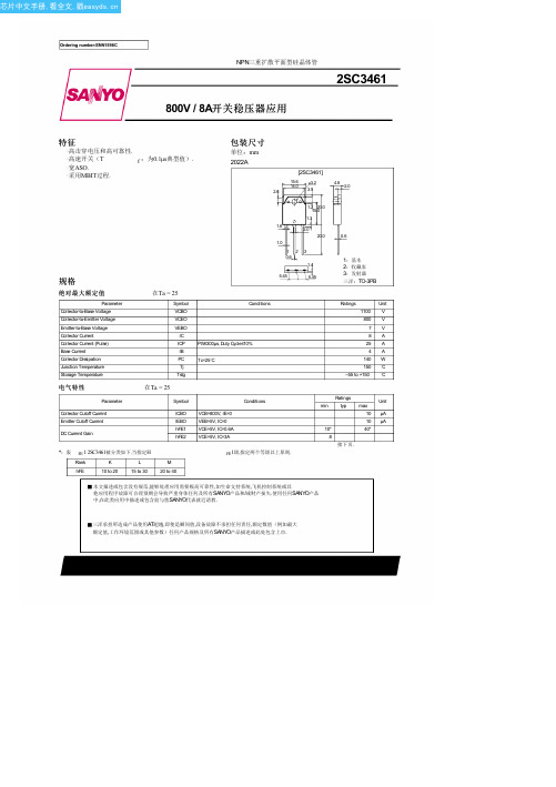
2SC3461中文资料(sanyo)中文数据手册「EasyDatasheet - 矽搜」
Ta=120°C
3
2
25°C
VCE=5V
10
--40°C
DC电7流增益,hFE
5
3 2
23
10 7 5
5 7 0.1 2 3 5 7 1.0 2 3 5 7 10
集电极电流,IC - 一个
ITR05612
VBE(星期六) - IC
IC / IB=5
3 2
基极 - 1发.0射极 Ta=--40°C 饱和电7 压,VBE(星期六) - V 25°C
5
3
2 23
120 °C
5 7 0.1 2 3 5 7 1.0
集电极电流,IC - 一个
2 3 5 7 10 ITR05614
No.1596–2/4
芯片中文手册,看全文,戳
2SC3461
IC -- VBE
9
VCE=5V
8
7
6 5 4
集电极电流,IC - 一个
3 2
2°0C Ta1=
三洋承担所造成产品使用AT超越,即使是瞬间值,设备故障不承担任何责任,额定数值(例如最大 额定值,工作环境范围或其他参数)任何产品规格及所有SANYO产品描述或此处包含上市.
芯片中文手册,看全文,戳
接上页.
Parameter
Gain-Bandwidth Product Output Capacitance Collector-to-Emitter Saturation Voltage Base-to-Emitter Saturation Voltage Collector-to-Base Breakdown Voltage Collector-to-Emitter Breakdown Voltage Emitter-to-Base Breakdown Voltage Collector-to-Emitter Sustain Voltage Turn-ON Time Storage Time Fall Time
伯朗特操作说明书
LNC-R6000 操作手冊
2012/03 版本:V01.00 ()
Leading Numerical Controller
东莞市伯朗特自动化科技有限公司
东莞市伯朗特自动化科技有限公司Biblioteka 1LNC-R6000
目录 1 2 3 LNC-R6000 塑胶机机械手控制系统简介...................................................... 1 画面编排说明............................................................................................... 3 原点 ............................................................................................................. 4
5
自动 ........................................................................................................... 10
5.1 核对 ................................................................................................................................................... 10 5.1.1 按键说明 ...................................................................................................................................11 5.1.2 自动运行中修改程式 .................................................................................................................11 5.2 5.3 5.4 5.5 IO 状态 .............................................................................................................................................. 12 堆迭设定 ............................................................................................................................................ 12 取样不良 ............................................................................................................................................ 12 周期监视 ............................................................................................................................................ 13 5.5.1 输送带设定............................................................................................................................... 14 5.5.2 加工机设定............................................................................................................................... 14
施耐德问题大全

施耐德电气的历史19世纪,施耐德电气从事钢铁工业、重型机械工业、轮船建造业;20世纪,从事电力与自动化管理业。
在成立的170多年里,施耐德电气遇到过无数次挑战,也做过数次重大战略选择,现在集团已经成长为行业领导者。
19世纪∙1836年:施耐德兄弟接管当时正处于困境的Creusot铸造厂(71),两年后他们成立了Schneider & Cie。
∙1891年:已成为专业武器制造商的施耐德开始进军当时新兴的电力市场,对自身进行了改革创新。
20世纪前50年∙1919年:通过欧洲工业和金融联盟(EIFU),施耐德在德国和东欧建立了基地。
在随后的几年里,施耐德与当时主要的国际电气集团西屋(Westinghouse)进行结盟,从而拓展了自己的业务范围,使其扩大到发电站、电气设备和电力机车的生产制造。
∙战后:施耐德逐渐停止武器制造,转向建筑、钢铁和电力行业。
为了实现公司业务的多样化以及打开新的市场,施耐德进行了整体的结构重组。
20世纪后期∙1981-1997年:施耐德电气抛开一些非战略活动,继续将重点放在电力工业上。
为了贯彻实施这项战略,施耐德进行了几次战略并购:TE电器、实快电力和梅兰日兰分别于1988年、1991年和1992成为施耐德电气集团的成员。
∙1999年:通过并购欧洲配电业第二大巨头Lexel,施耐德在超终端领域取得了巨大发展。
1999年5月,集团改名为施耐德电气,更加明确地强调了公司专业致力于电气领域。
改名之后的施耐德电气采取加速发展、提高市场竞争力的战略。
∙2000-2005年:随着自身结构的发展和公司合并政策的贯彻,施耐德电气在新的市场细分中进行了自身定位,这些市场细分包括:人机对话、不间断电源(UPS)、运动控制、声音数据图像系统、传感技术、建筑自动化和安全(如Digital、Crouzet、Clipsal、MGE不间断电源系统、TAC、Kavlico、Andover控制等)等。
TE电器的历史自创立以来,TE电器品牌将创新作为自己的一贯策略。
电气工程及其自动化专业毕业论文-单片机电机控制
xx大学毕业设计(论文)题目:单片机实现的步进电机控制系统设计作者:系(部):专业班级:指导教师:职称:20 年月日步进电机控制系统的组成如图4.1所示:图4.1 控制系统图3、本课题需要重点研究的、关键的问题及解决的思路[8]步进电机控制程序设计的主要问题有三个:第一、控制脉冲产生;第二、步进电机的旋转方向和时序脉冲的关系;第三、步数的确定。
作为单片机控制步进电机的程序的构成也是主要由这几个问题,因此可以从这三个问题入手:(1)控制脉冲的产生在单片机控制步进电机时,一般来讲,控制是用软件产生的。
方法是先输出一个高电平,然后延时,再输出低电平,再进行延时。
延时时间的长短由步进电机的工作频率决定。
(2)步进电机的旋转方向和时序脉冲的关系产生时序脉冲的方法是:1 单片机的IO 端口,分别控制三相步进电机的A, B, C 三相绕组;2 控制模式写出控制模型;2 制模型的顺序向步进电机输入控制脉冲。
(3)步数的确定步进电机运行的步数可由步距角和需要转过的角度来计算:NZ r b ⋅︒=360θ 式中:b θ-步距角;r Z -转子齿数; N -拍数(一般三拍时N =m 或六拍时N =2m );m -控制绕组相数,m =3毕业设计(论文)任务书学生姓名_1111指导教师_黄云龙、廖东进、朱秋琴职称副教授、助教、助教系别_信息与电子工程系_专业电气年级 03级___班级课题名称单片机实现的步进电机控制系统设计任务与要求:一、设计(论文)要求:本课题的主要任务是通过单片机控制系统,实现对步进电机工作状态的控制。
具体设计方案如下:本设计采用凌阳16 位单片机SPCE061A对步进电机进行控制,通过IO 口输出的具有时序的方波作为步进电机的控制信号,信号经过芯片L298N驱动步进电机;同时,用4X4的键盘来对电机的状态进行控制,并用数码管显示电机的转速,采用74LS164作为4位单个数码管的显示驱动,从单片机输入信号;利用凌阳单片机的语音功能播报电机的转速。
LKS561 数据手册说明书
南京凌鸥创芯电子有限公司LKS561数据手册@ 2019, 版权归凌鸥创芯所有机密文件,未经许可不得扩散目录1概述 (1)1.1功能简述 (1)1.2主要指标 (1)1.3控制逻缉 (2)2管脚分布 (3)2.1管脚分布图 (3)2.2管脚说明 (3)3封装尺寸 (4)4应用示例 (5)5电气性能参数 (6)5.1极限参数 (6)5.2建议工况 (6)5.3动态电气参数 (6)5.4静态电气参数 (8)6版本历史 (9)表1-1 主要指标参数 (1)表2-1 LKS561管脚说明 (3)表3-1 LKS560封装尺寸 (4)表5-1 LKS561极限参数表 (6)表5-2 LKS561建议工作参数表 (6)表5-3 LKS561动态电气参数表 (7)表5-4 LKS561 静态电气参数 (8)表6-1 文档版本历史 (9)图1-1 LKS561内部结构框图 (1)图1-2 LKS561控制逻辑时序图 (2)图2-1 LKS561管脚分布图 (3)图3-1 LKS560封装图示 (4)图4-1 典型应用图示 (5)图4-2 大电流负载应用图示 (5)图5-1 时序参数t on/t off/t f定义 (7)图5-2 时序参数MT定义 (7)图5-3 死区时序定义 (7)1 概述1.1 功能简述LKS561是一款用于驱动MOS/IGBT 栅极的集成电路,芯片有高侧驱动输出和低侧驱动输出两组,可同时驱动两个MOS/IGBT 器件,其中高侧器件通过浮动管脚实现电压抬升,最高耐压达+300V 。
输入信号可兼容CMOS 和LSTTL 电平。
HINLINVCCLOCOMVBHO VS图 1-1 LKS561内部结构框图1.2 主要指标➢ 高侧驱动采用浮动电源设计,最高耐压+300V ➢ 可承受瞬时负压➢ 芯片电源供电范围10~25V ➢ 欠压保护功能➢ 输入电平3.3/5/15V 兼容 ➢ 双通道延时匹配表 1-1 主要指标参数死区时间200ns工作温度-40℃~150℃1.3控制逻缉控制逻缉如图1.2所示:高侧控制端HIN高电平有效,低侧控制端LIN同样高电平有效,当高侧低侧同时有效时,输出禁止。
施耐德微型断路器选型以及所有型号参考-长沙自动化技术支持182-2987-4140
OSMC32N4B63OSMC32:这个是微型断路器系列N4:这个为断路器的接线端子数B:保护短路电流较小的负载(如电源、长电览等),不过一般选C {当然这里可以是“C”保护常规负载和配电线缆或者“D ”保护起动电流大的冲击性负荷 (如电动机,变压器等)}63:这个就是我们要选择的脱扣电流,我们低压元器件中选断路器(高压我不太了解),就是选这个电流,这个电流一般是额定电流的 1.5到2倍就可以啦,选小了电机稍微一过载断路器就跳了,选大了,电机烧了他都不跳。
OSMC32N1C1 OSMC32N 小型断路器 1P C1AOSMC32N1C2 OSMC32N 小型断路器 1P C2AOSMC32N1C3 OSMC32N 小型断路器 1P C3AOSMC32N1C4 OSMC32N 小型断路器 1P C4AOSMC32N1C6 OSMC32N 小型断路器 1P C6AOSMC32N1C10 OSMC32N 小型断路器1P C10AOSMC32N1C16 OSMC32N 小型断路器1P C16AOSMC32N1C20 OSMC32N 小型断路器1P C20AOSMC32N1C25 OSMC32N 小型断路器1P C25AOSMC32N1C32 OSMC32N 小型断路器1P C32AOSMC32N1C40 OSMC32N 小型断路器1P C40AOSMC32N1C63 OSMC32N 小型断路器1P C63AOSMC32N2C1 OSMC32N 小型断路器 2P C1A OSMC32N2C2 OSMC32N 小型断路器 2P C2A OSMC32N2C3 OSMC32N 小型断路器 2P C3A OSMC32N2C4 OSMC32N 小型断路器 2P C4A OSMC32N2C6 OSMC32N 小型断路器 2P C6A OSMC32N2C10 OSMC32N 小型断路器2P C10A OSMC32N2C16 OSMC32N 小型断路器2P C16A OSMC32N2C20 OSMC32N 小型断路器2P C20A OSMC32N2C25 OSMC32N 小型断路器2P C25A OSMC32N2C32 OSMC32N 小型断路器2P C32A OSMC32N2C40 OSMC32N 小型断路器2P C40A OSMC32N2C50 OSMC32N 小型断路器2P C50A OSMC32N2C63 OSMC32N 小型断路器2P C63AOSMC32N3C1 OSMC32N小型断路器 3P C1A OSMC32N3C2 OSMC32N小型断路器 3P C2A OSMC32N3C3 OSMC32N小型断路器 3P C3A OSMC32N3C4 OSMC32N小型断路器 3P C4A OSMC32N3C6 OSMC32N小型断路器 3P C6AOSMC32N3C16 OSMC32N小型断路器3P C16A OSMC32N3C20 OSMC32N小型断路器3P C20A OSMC32N3C25 OSMC32N小型断路器3P C25A OSMC32N3C32 OSMC32N小型断路器3P C32A OSMC32N3C40 OSMC32N小型断路器3P C40A OSMC32N3C50 OSMC32N小型断路器3P C50A OSMC32N3C63 OSMC32N小型断路器3P C63AOSMC32N4C1 OSMC32N小型断路器 4P C1A OSMC32N4C2 OSMC32N小型断路器 4P C2A OSMC32N4C3 OSMC32N小型断路器 4P C3A OSMC32N4C4 OSMC32N小型断路器 4P C4A OSMC32N4C6 OSMC32N小型断路器 4P C6A OSMC32N4C10 OSMC32N小型断路器4P C10A OSMC32N4C16 OSMC32N小型断路器4P C16A OSMC32N4C20 OSMC32N小型断路器4P C20A OSMC32N4C25 OSMC32N小型断路器4P C25A OSMC32N4C32 OSMC32N小型断路器4P C32A OSMC32N4C40 OSMC32N小型断路器4P C40A OSMC32N4C50 OSMC32N小型断路器4P C50A OSMC32N4C63 OSMC32N小型断路器4P C63AOSMC32N1D1 OSMC32N小型断路器 1P D1A OSMC32N1D2 OSMC32N小型断路器 1P D2A OSMC32N1D3 OSMC32N小型断路器 1P D3A OSMC32N1D4 OSMC32N小型断路器 1P D4A OSMC32N1D6 OSMC32N小型断路器 1P D6A OSMC32N1D10 OSMC32N小型断路器1P D10A OSMC32N1D16 OSMC32N小型断路器1P D16A OSMC32N1D20 OSMC32N小型断路器1P D20A OSMC32N1D25 OSMC32N小型断路器1P D25A OSMC32N1D32 OSMC32N小型断路器1P D32A OSMC32N1D40 OSMC32N小型断路器1P D40A OSMC32N1D50 OSMC32N小型断路器1P D50A OSMC32N1D63 OSMC32N小型断路器1P D63AOSMC32N2D1 OSMC32N小型断路器 2P D1A OSMC32N2D2 OSMC32N小型断路器 2P D2A OSMC32N2D3 OSMC32N小型断路器 2P D3A OSMC32N2D4 OSMC32N小型断路器 2P D4A OSMC32N2D6 OSMC32N小型断路器 2P D6A OSMC32N2D10 OSMC32N小型断路器2P D10A OSMC32N2D16 OSMC32N小型断路器2P D16AOSMC32N2D25 OSMC32N小型断路器2P D25A OSMC32N2D32 OSMC32N小型断路器2P D32A OSMC32N2D40 OSMC32N小型断路器2P D40A OSMC32N2D50 OSMC32N小型断路器2P D50A OSMC32N2D63 OSMC32N小型断路器2P D63AOSMC32N3D1 OSMC32N小型断路器 3P D1A OSMC32N3D2 OSMC32N小型断路器 3P D2A OSMC32N3D3 OSMC32N小型断路器 3P D3A OSMC32N3D4 OSMC32N小型断路器 3P D4A OSMC32N3D6 OSMC32N小型断路器 3P D6A OSMC32N3D10 OSMC32N小型断路器3P D10A OSMC32N3D16 OSMC32N小型断路器3P D16A OSMC32N3D20 OSMC32N小型断路器3P D20A OSMC32N3D25 OSMC32N小型断路器3P D25A OSMC32N3D32 OSMC32N小型断路器3P D32A OSMC32N3D40 OSMC32N小型断路器3P D40A OSMC32N3D50 OSMC32N小型断路器3P D50A OSMC32N3D63 OSMC32N小型断路器3P D63AOSMC32N4D1 OSMC32N小型断路器 4P D1AOSMC32N4D3 OSMC32N小型断路器 4P D3A OSMC32N4D4 OSMC32N小型断路器 4P D4A OSMC32N4D6 OSMC32N小型断路器 4P D6A OSMC32N4D10 OSMC32N小型断路器4P D10A OSMC32N4D16 OSMC32N小型断路器4P D16A OSMC32N4D20 OSMC32N小型断路器4P D20A OSMC32N4D25 OSMC32N小型断路器4P D25A OSMC32N4D32 OSMC32N小型断路器4P D32A OSMC32N4D40 OSMC32N小型断路器4P D40A OSMC32N4D50 OSMC32N小型断路器4P D50A OSMC32N4D63 OSMC32N小型断路器4P D63AOSMC32N1B1 OSMC32N 小型断路器 1P B1A OSMC32N1B2 OSMC32N 小型断路器 1P B2A OSMC32N1B3 OSMC32N 小型断路器 1P B3A OSMC32N1B4 OSMC32N 小型断路器 1P B4A OSMC32N1B6 OSMC32N 小型断路器 1P B6A OSMC32N1B10 OSMC32N 小型断路器1P B10A OSMC32N1B16 OSMC32N 小型断路器1P B16A OSMC32N1B20 OSMC32N 小型断路器1P B20A OSMC32N1B25 OSMC32N 小型断路器1P B25AOSMC32N1B40 OSMC32N 小型断路器1P B40A OSMC32N1B50 OSMC32N 小型断路器1P B50A OSMC32N1B63 OSMC32N 小型断路器1P B63A OSMC32N2B1 OSMC32N 小型断路器 2P B1A OSMC32N2B2 OSMC32N 小型断路器 2P B2A OSMC32N2B3 OSMC32N 小型断路器 2P B3A OSMC32N2B4 OSMC32N 小型断路器 2P B4A OSMC32N2B6 OSMC32N 小型断路器 2P B6A OSMC32N2B10 OSMC32N 小型断路器2P B10A OSMC32N2B16 OSMC32N 小型断路器2P B16A OSMC32N2B20 OSMC32N 小型断路器2P B20A OSMC32N2B25 OSMC32N 小型断路器2P B25A OSMC32N2B32 OSMC32N 小型断路器2P B32A OSMC32N2B40 OSMC32N 小型断路器2P B40A OSMC32N2B50 OSMC32N 小型断路器2P B50A OSMC32N2B63 OSMC32N 小型断路器2P B63A OSMC32N3B1 OSMC32N 小型断路器 3P B1A OSMC32N3B2 OSMC32N 小型断路器 3P B2A OSMC32N3B3 OSMC32N 小型断路器 3P B3A OSMC32N3B4 OSMC32N 小型断路器 3P B4A OSMC32N3B6 OSMC32N 小型断路器 3P B6AOSMC32N3B16 OSMC32N 小型断路器3P B16A OSMC32N3B20 OSMC32N 小型断路器3P B20A OSMC32N3B25 OSMC32N 小型断路器3P B25A OSMC32N3B32 OSMC32N 小型断路器3P B32A OSMC32N3B40 OSMC32N 小型断路器3P B40A OSMC32N3B50 OSMC32N 小型断路器3P B50A OSMC32N3B63 OSMC32N 小型断路器3P B63A OSMC32N4B1 OSMC32N 小型断路器 4P B1A OSMC32N4B2 OSMC32N 小型断路器 4P B2A OSMC32N4B3 OSMC32N 小型断路器 4P B3A OSMC32N4B4 OSMC32N 小型断路器 4P B4A OSMC32N4B6 OSMC32N 小型断路器 4P B6A OSMC32N4B10 OSMC32N 小型断路器4P B10A OSMC32N4B16 OSMC32N 小型断路器4P B16A OSMC32N4B20 OSMC32N 小型断路器4P B20A OSMC32N4B25 OSMC32N 小型断路器4P B25A OSMC32N4B32 OSMC32N 小型断路器4P B32A OSMC32N4B40 OSMC32N 小型断路器4P B40A OSMC32N4B50 OSMC32N 小型断路器4P B50A OSMC32N4B63 OSMC32N 小型断路器4P B63A施耐德OSMC32小型断路器smart系列产品是面向工业控制领域,为OEM(原始设备制造商)量身定做低压配电产品,具有多项国际认**,方便OEM用户的国内使用和设备出口。
充电保护IC分类

单节锂电池保护新方案:集成“保护IC”+“MOS管”于一个芯片中这个锂电池保护方案为美国科园CARETTA之新研发上市产品,目前市场上无同类芯片。
此IC为锂电保护IC和MOSFET合二为一的产品,因此,它的专业叫法为COMBO。
有三个产品型号CR6001,CR6002和CR6003,它们都只能应用在一节锂电上(手机电池,数码电池,蓝牙电池,备用电池等)。
产品特点内置MOSFET低内阻极少的外部元器件(只需一个电容,现流行的产品要三个电容,二个电阻)过充电流保护三级过放电流保护低功耗环保过温保护1.PRODUCT family Available for CR6001PRODUCT MODEL VCU VHC VDL VHD IODC1 IODC2 TCU RDS PACKAGECR6001A 4.275 0.25 2.5 0.4 3.0 6.0 1200 24 MSOP-8CR6001B 4.275 0.25 2.9 0.4 3.0 6.0 1200CR6001D 4.325 0.175 2.5 0.4 3.0 6.0 500CR6001E 4.325 0.175 2.5 0.4 3.0 6.0 1200CR6001F 4.275 0.20 2.5 0.4 3.0 8.0 12002.PRODUCT family Available for CR6002PRODUCT MODEL VCU VHC VDL VHD IODC1 IODC2 TCU RDS PACKAGECR6002A 4.275 0.25 2.5 0.4 3.0 6.0 1200 29 MSOP-8CR6002B 4.275 0.25 2.9 0.4 3.0 6.0 1200CR6002D 4.325 0.175 2.5 0.4 3.0 6.0 500CR6002E 4.325 0.175 2.5 0.4 3.0 6.0 1200CR6002F 4.275 0.20 2.5 0.4 3.0 8.0 12003.PRODUCT family Available for CR6003PRODUCT MODEL VCU VHC VDL VHD IODC1 IODC2 TCU RDS PACKAGECR6003A 4.275 0.25 2.5 0.4 3.0 6.0 1200 34 SOT-23-6CR6003B 4.275 0.25 2.9 0.4 3.0 6.0 1200CR6003D 4.325 0.175 2.5 0.4 3.0 6.0 500CR6003E 4.325 0.175 2.5 0.4 3.0 6.0 1200CR6003F 4.275 0.20 2.5 0.4 3.0 8.0 1200市场分类一级市场现流行的保护IC产品型号及MOS型号:保护IC型号:R5421 , R5426(Rioch);S-8241,S-8261(SEIKO.html">SEIKO);MM3077,MM3090,MM3099(mitsumi)MOS型号:MCH6405(SANYO.html">SANYO),TPC8209(TOSHIBA),FSD2502(FAIRCHILD.html">FAIRCHILD)二级市场现流行的保护IC产品型号及MOS型号:保护IC型号:DW01(富晶),CS213(新德),SC451(仕兰微),AM7021(中星微)MOS型号:FSD9926(FAIRCHILD.html">FAIRCHILD);AO8810,AO9926(AOSMD);STS5DNF20V(ST)三级市场现流行的保护IC产品型号及MOS型号:CS213(新德)+单MOS的产品科园产品所对应的市场:CR6001用在高端市场的保护板中,主要取代應用RICHO, SEIKO的保護IC 及ST, SANYO的MOSFET. 科园CR6001 的品質跟他們相當, 整體格價有5-10%的優勢.CR6002用在中端市场的保护板中,主要取代應用“富晶”, “中興微” 的保護IC 及FAIRCHILD的MOSFET. 科园CR6002 的品質跟他們相當, 整體格價有5-10%的優勢。
Ra-01S规格书说明书
Ra-01S规格书版本V1.1版权©2020免责申明和版权公告本文中的信息,包括供参考的URL地址,如有变更,恕不另行通知。
文档“按现状”提供,不负任何担保责任,包括对适销性、适用于特定用途或非侵权性的任何担保,和任何提案、规格或样品在他处提到的任何担保。
本文档不负任何责任,包括使用本文档内信息产生的侵犯任何专利权行为的责任。
本文档在此未以禁止反言或其他方式授予任何知识产权使用许可,不管是明示许可还是暗示许可。
文中所得测试数据均为安信可实验室测试所得,实际结果可能略有差异。
文中提到的所有商标名称、商标和注册商标均属其各自所有者的财产,特此声明。
最终解释权归深圳市安信可科技有限公司所有。
注意由于产品版本升级或其他原因,本手册内容有可能变更。
深圳市安信可科技有限公司保留在没有任何通知或者提示的情况下对本手册的内容进行修改的权利。
本手册仅作为使用指导,深圳市安信可科技有限公司尽全力在本手册中提供准确的信息,但是深圳市安信可科技有限公司并不确保手册内容完全没有错误,本手册中的所有陈述、信息和建议也不构成任何明示或暗示的担保。
文件制定/修订/废止履历表版本日期制定/修订内容制定核准V1.02020.8.12首版徐V1.12020.8.19更新部分参数徐目录一、产品概述 (5)二、电气参数 (6)三、外观尺寸 (8)四、管脚定义 (10)五、原理图 (11)六、设计指导 (12)七、回流焊曲线图 (14)八、包装信息 (15)九、联系我们 (15)一、产品概述安信可LoRa系列模块(Ra-01S)由安信可科技设计开发。
该模组用于超长距离扩频通信,其射频芯片SX1268主要采用LoRa™远程调制解调器,用于超长距离扩频通信,抗干扰性强,能够最大限度降低电流消耗。
借助SEMTECH的LoRa™专利调制技术,SX1268具有超过-148dBm的高灵敏度,+22dBm的功率输出,传输距离远,可靠性高。
同时,相对传统调制技术,LoRa™调制技术在抗阻塞和选择方面也具有明显优势,解决了传统设计方案无法同时兼顾距离、抗干扰和功耗的问题。
伟肯变频器用户手册
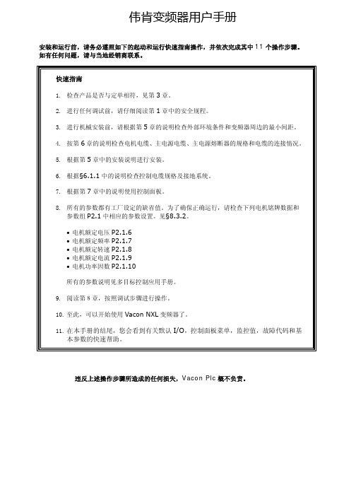
伟肯变频器用户手册安装和运行前,请务必遵照如下的起动和运行快速指南操作,并依次完成其中11个操作步骤。
如有任何问题,请与当地经销商联系。
快速指南1. 检查产品是否与定单相符,见第3章。
2. 进行任何调试前,请仔细阅读第1章中的安全规程。
3. 进行机械安装前,请根据第5章的说明检查外部环境条件和变频器周边的最小间距。
4. 按第6章的说明检查电机电缆、主电源电缆、主电源熔断器的规格和电缆的连接情况。
5. 根据第5章中的安装说明进行安装。
6. 根据§6.1.1中的说明检查控制电缆规格及接地系统。
7. 根据第7章中的说明使用控制面板。
8. 所有的参数都有工厂设定的缺省值。
为了确保正确运行,请检查下列电机铭牌数据和参数组P2.1中相应的参数设置。
见§8.3.2。
• 电机额定电压P2.1.6• 电机额定频率P2.1.7• 电机额定转速P2.1.8• 电机额定电流P2.1.9• 电机功率因数P2.1.10所有的参数说明见多目标控制应用手册。
9. 阅读第8章,按照调试步骤进行操作。
10. 至此,可以开始使用Vacon NXL变频器了。
11. 在本手册的结尾,您会看到有关默认I/O,控制面板菜单,监控值,故障代码和基本参数的快速帮助。
违反上述操作步骤所造成的任何损失,Vacon Plc概不负责。
目录VACON NXL用户手册目录1 安全指导2 EU认证3 收货4 技术数据5 安装6 电缆和接线7 控制面板8 调试9 故障跟踪10 选件卡OPT-AA的描述11 选件卡OPT-AI的描述VACON NXL多目标控制应用手册vacon • 3Vacon China电话: +86-10-51280006 传真: +86-10-65813733 24小时支持热线: +86-137******** Email :***************.cn关于VACON NXL 用户手册和多目标控制应用手册恭喜您选择了Vacon NXL 变频器所提供的平滑控制!用户手册将为您提供有关Vacon NXL 变频器的安装,调试和操作的必要信息。
三光三相IO-Link电流监测保护电器说明书

100 000 K 2%
Supply voltage Type of voltage of the supply voltage Supply voltage 1 at DC rated value Relative negative tolerance of the supply voltage Relative positive tolerance of the supply voltage
DC 24 V 25 % 25 %
Measuring circuit Type of current for monitoring Adjustable pick-up value current ●1 ●2 Adjustable response delay time ● when starting ● with lower or upper limit violation Adjustable switching hysteresis for measured current value Accuracy of digital display
● at 24 V ● at 125 V ● at 250 V Contact rating of auxiliary contacts according to UL
Main circuit Operating power ● rated value
Outputs Ampacity of the semiconductor output in SIO mode Operating current at 17 V minimum
RC3-8-01S资料

10.0
2.0
6.0 4.0 CURRENT (AMPS)
8.0
10.0
` For performance information in a vacuum or with hot side temperatures other than 27°C or 50°C, consult one of our Applications Engineers.
Addresses
Marlow Industries, Inc. 10451 Vista Park Road Dallas Texas 75238-1645 214-340-4900 (tel) 214-341-5212 (fax) Marlow Industries Europe Aberdeen House, South Road Haywards Heath West Sussex RH164NG UK +44 (0)1444-443404 (tel) +44 (0)1444-443334(fax) Marlow Industries Japan 1-1-8-401 Uehara, Shibuya-ku Tokyo, Japan 151-0064 +81 (3) 5454-5280 (tel) +81 (3) 5454-5281(fax)
RoHS 2002/95/EC Compliant
Mechanical Characteristics
+
MARLOW RC 3-8 L
POSITIVE LEAD (WHITE) .48±.24 [12.19±6.10] 20 AWG LEADS, TEFLON INSULATED NEGATIVE LEAD (BLACK) 4.00 ±.50 [101 ± 13]
西门子 低压电器元器件 快速选型手册

如果您在选型时遇到任何问题欢迎来电垂询。
热线电话为:010-********或者800 810 42881234567低压电器元器件快速选型手册5691215框架和塑壳断路器根据变压器的额定电流和短路电流选择断路器…3WL 空气断路器 ……………………………………3WT 空气断路器 ……………………………………3VL 塑壳断路器 ……………………………………3VT 塑壳断路器 ..........................................微型断路器小型断路器产品一览....................................漏电保护器产品一览表.................................微型断路器附件选配一览表...........................小型断路器选型表.......................................熔断器快速选型表.......................................控制产品及软起动器 .....................标准变频器选型表 ...........................面板开关DELTA vega “灵动”系列总览.....................DELTA vista “远景”系列总览 .....................EIB 电气安装总线 EIB 系统描述 ...........................电气安装总线 EIB 系统设计 ...........................S I VACON 8PT 开关柜 (25333940414143)17181920245ՎS n =Վ I n = Վ U k=Վ I s c =ǖ I s c I E C Ք3WL1.2. ǖ Ă ĂĂ3.4. 10. 11. 12. ӱ13. ӱLj 14. Ӏ Lj 15. 16. 17. DŽBSS Dž18. DŽETU Dž19. 20. DŽBDA Dž21.4 22. ԍ 23. 24.25. Ԩ3WL 65.Ҿ ӱ6. COM15 PROFIBUS7. ևCubicle BUS8. Lj9.71) I I I n m a x ≤2500A 5) E T U 155 =85m s 2) I I I n m a x ≤3200A6) N ǖ LjH ǖՔ LjL ǖ3) I I I I n m a x ≤5000A 7) E T U 15B4)I IIIn ma x ≤63A框架和塑壳断路器√标准○可选-不存在1)固定注:具体参数请参考技术手册891. 2. Ӏ Lj ǖlj lj 3. 4.5. Ԣǖ3WT Lj Lj I Lj3ǖ3WT Lj Lj I Lj311.12. դ13. դ6. (ON)Ӏ7. (OFF)Ӏ8.9.10.3WT框架和塑壳断路器3WT技术数据1) 如果需要更大的额定值和通讯能力,请使用SENTRON 3WL断路器。
CSNC361中文资料

CSNC361中⽂资料Closed Loop Current SensorsFEATURES ?Current sensing up to 1200amps ?Measures AC,DC and impulse currents ?Lowest cost/performance ratio ? Rapid response,no overshoot ?High overload capacity ?High level of electrical isolation between primary and secondary circuits ?Small size and weight CLOSED LOOP SENSORS Closed loop current sensors measure AC,DC and impulse currents over 0-25,0-50,0-100,0-600and 0-1200Amp rang-es.The CSN Series is based on the princi-ples of the Hall effect and the null balance or zero magnetic flux method (feedback system).The magnetic flux in the sensor core is constantly controlled at zero.The amount of current required to balance zero flux is the measure of the primary current flowing through the conductor,multiplied by the ratio of the primary to secondary windings.This closed loop current is the output from the device and presents an image of the primary current reduced by the number of secondary turns at any time.This current can be expressed as a voltage by passing it through a resistor.CATALOG NUMBER SYSTEM PLEASE NOTE:This matrix is intended only to aid you in identifying sensor cata-log listings.It is not all-inclusive,and must not be used to form new listings.Example:CSNA111CSN Closed Loop Current SensorCurrent Range (Peak/RMS nom.)A ±70A/50A rms nom.B ±100A/50A rms nom.C ±90A/50A rms nom.D ±22A/15A rms nom.E ±36A/25A rms nom.F ±150A/100A rms nom.J ±600A/300A rms nom.K ±1200A/500A rms nom.L ±600A/300A rms nom.M±1200A/500A rms nom.P ±90A/50A rms nom.R ±200A/125A rms nom.T ±150A/50A rms nom.Supply Voltage 1±15V 2±13V 3±5V 4±12V to 18V 5±15V to 24V 6±12V to 15VCoil Characteristics 11:1000turns/90?@70°C 21:2000turns/160?@70°C 31:2000turns/130?@70°C 41:1000turns/50?@70°C 51:1000turns/110?@70°C 61:1000turns/30?@70°C 71:2000turns/80?@70°C 81:2000turns/25?@70°C91:5000turns/50?@85°CHousing Material 1Polycarbonate/ABS blend PDFINFOClosed Loop Current Sensors*Contact the 800number for more information.SPECIFICATIONSCatalog Listing CSNA111CSNB121CSNB131CSNE151Offset Current @25°C,mA max.±0.20±0.10±0.10±0.10Temperature Drift,0to 70°C,mA ±0.35typ.±0.20typ.±0.20typ.±0.17typ.±0.60max.±0.30max.±0.30max.±0.60max.Linearity 0.1%0.1%0.1%0.2%SupplyVoltage ±15V ±15V ±15V ±15VGalvanic Isolation @50Hz/1min. 2.5kV rms 5kV rmsAccuracy ±0.5%of I N (nominal Current)at 25°CResponse Time <1?sBandwidth DC to 150kHzTemperature Operating:0to 70°C (32to 150°F)Storage:?25to 85°C (?13to 185°F)Primary Circuit Connection Thru-hole Thru-hole Thru-hole Invasive on 10pins Secondary Circuit Connection 3Pins 3Pins 3Pins 3PinsCurrent Drain 10mA (no load current)+output current (secondary current)‘‘In-Out’’Sense Signal To obtain positive measuring current on O/P terminal,current must flow in direction of arrow Mounting PCB,3pins,hole size 0.95mm PCB,13pins PRIMARY PIN CONNECTIONS FOR CSNE151Primary CurrentPrimary Turns Nom.I DN (A)Max.I D (A)OutputCurrent (mA)PrimaryResistance (m ?)Primary PinConnections 12436250.32121824 1.1381224 2.546924 4.455725 6.3WIRING DIAGRAMSCSNA111/CSNB121/CSNB131CSNE151PDFINFOCurrentClosed Loop Current Sensors MOUNTING DIMENSIONS(for reference only) CSNA111,CSNB121,CSNB131CSNE151/CSNE381CSNH151PDFINFOClosed Loop Current SensorsSPECIFICATIONSCatalog ListingsCSNJ481CSNJ481-002CSNK591CSNK591-002CSNJ481-001CSNJ481-003CSNK591-001CSNK591-003Offset Current @25°C,mA max.±0.30±0.30±0.20±0.20Temperature Drift,0to 70°C,mA ±0.30typ.±0.30typ.±0.20typ.±0.20typ.±0.50max.±0.50max.±0.30max.±0.30max.Linearity±0.1%±0.1%±0.1%±0.1%Supply Voltage ±12to ±18V ±12to ±18V ±15to ±24V ±15to ±24V Galvanic Isolation @50Hz/1min.7.5kV rms 7.5kV rms 6kV rms 6kV rmsAccuracy ±0.5%of I N (nominal Current)at 25°CResponse Time <1?sBandwidth DC to 150kHzOperating Temperature ?40to 85°C 0to 70°C ?40to 85°C 0to 70°C (?40to 185°F)(32to 158°F (?40to 185°F)(32to 158°F)Storage Temperature ?40to 90°C ?25to 85°C ?40to 90°C ?25to 85°C (?40to 194°F)(?13to 85°F (?40to 194°F)(? 13to 85°F)Primary Circuit Connection Thru-hole or busbar Thru-hole or busbar Thru-hole or busbar Thru-hole or busbar Secondary Circuit Connection 3pins 3pins 3pins 3pinsCurrent Drain 14mA (no load current)+output current 22mA (24V)+output current‘‘In-Out’’Sense Signal To obtain positive measuring current on O/P terminal,current must flow in direction of arrow Mounting Faston,3pins Push-on (spade),3terminalsWIRING DIAGRAMPDFINFOCurrentClosed Loop Current Sensors MOUNTING DIMENSIONS(for reference only) CSNJ481CSNK591PDFINFOClosed Loop Current SensorsSPECIFICATIONSCatalog ListingsCSNL181CSNM191Offset Current@25°C,mA max.±0.30±0.20Temperature Drift,0to70°C,mA±0.30typ.±0.20typ.±0.50max.±0.30max.Linearity±0.1%±0.1%Supply Voltage±12to±18V±12to±18VGalvanic Isolation@50Hz/1min.7.5kV rms7.5kV rmsAccuracy±0.5%of I N(nominal Current)at25°CResponse Time500ns<1?sBandwidth DC to150kHzOperating Temperature?40to85°C(?40to185°F)Storage Temperature?40to90°C(?40to194°F)Primary Circuit Connection Thru-hole Thru-holeSecondary Circuit Connection3pins3pinsCurrent Drain14mA(no load current)+output current‘‘In-Out’’Sense Signal To obtain positive measuring current on O/P terminal,current must flowin direction of arrowMounting Faston,3pinsWIRING DIAGRAMPDFINFO CurrentClosed Loop Current Sensors MOUNTING DIMENSIONS(for reference only) CSNL181CSNM191PDFINFOClosed Loop Current SensorsSPECIFICATIONSCatalog ListingsCSNP661CSNT651CSNF161CSNF151CSNR161CSNR151Offset Current @25°C,mA max.±0.20±0.10±0.20±0.10±0.20±0.10Temperature Drift,0to 70°C,mA ±0.30typ.±0.15typ.±0.30typ.±0.15typ.±0.30typ.±0.15typ.±0.50max.±0.25max.±0.50max.±0.25max.±0.60max.±0.30max.Linearity ±0.1%±0.1%±0.1%±0.1%±0.1%±0.1%Supply Voltage ±12to 15V ±12to 15V ±12to 15V ±12to 15V ±12to 15V ±12to 15V Galvanic Isolation @50Hz/1min.3kV rms 3kV rms 3kV rms 3kV rms 3kV rms 3kV rms Accuracy ±0.5%of I N (nominal Current)at 25°CResponse Time <500nsBandwidth DC to 150kHzOperating Temperature ?40to 85°C (?40to 185°F)?40to 85°C (?40to 185°F)Storage Temperature ?40to 90°C (?40to 194°F)?40to 90°C (?40to 194°F)Primary Circuit Connection Thru-holeSecondary Circuit Connection 3pinsCurrent Drain 10mA (no load current)+output current 14mA (no load current)+output current‘‘In-Out’’Sense Signal To obtain positive measuring current on O/P terminal,current must flow in direction of arrow Mounting 3pinsPin Style A A B B B B WIRING DIAGRAMPDFINFOCurrentClosed Loop Current Sensors MOUNTING DIMENSIONS(for reference only)PDFINFO。
Firetrol Mark IIXG型电动消防泵控制器使用手册说明书
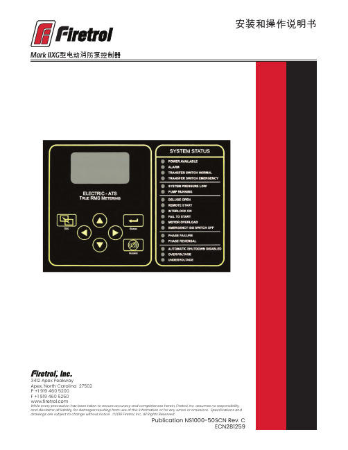
安装和操作说明书Fire Pump Controllers General InformationCalifornia Proposition 65WarningWARNING : This product can expose you to chemicals including DINP, which is known to the State of California to cause cancer, and DIDP which is known to the State of California to cause birth defects or other reproductive harm.WARNING : This product can expose you to chemicals including lead and lead compounds, which are know to the State of California to cause cancer and birth defects or other reproductive harm.For more information go to: 3412 Apex Peakway Apex, North Carolina 27502P +1 919 460 5200F +1 919 460 目 录介绍 (1)安装控制器 (2)墙式安装 (2)地板/基座式安装 ....................................................................................................................2-3电气连接 ................................................................................................................................3-4系统压力连接管 . (4)一般预启动操作 (4)一般启动操作 (4)相位旋转 (5)电机旋转方向FTA750、1000、1500、1800、2000、2400控制器 (5)FTA1250 控制器 (5)FTA1300、1350 控制器..............................................................................................5-6 FTA1930 控制器 . (6)FTA900、975电源转换开关 (6)FTA950、976电源转换开关 (6)初始启动操作 (7)手动启动 (7)应急运行启动 (7)简单启动顺序FTA750, 1000, 2000, 2400 (7)FTA1250 .....................................................................................................................7-8 FTA1300, 1350 (8)FTA1500 (8)FTA1800 (8)FTA1930 (8)型IIXG程序设置用户界面和显示器 (9)用户菜单结构 (10)程序设置说明 (11)菜单设置系统设置显示亮度 (12)对比度 (12)反向 (12)键盘 (12)语言和单元语言 (12)压力单位 (12)密码1级 (12)2级 (12)日期和时间时间 (12)日期 (12)日期格式 (12)日光节约 (13)定时器延时开机 (13)最短运行/关机延迟 (13)加速 (13)子系统旁路 (13)压力压力单位 (14)启动 (14)停止 (14)禁用自动停机 (14)过压报警 (14)记录 -德耳塔 (14)传感器 (14)校正 (14)恢复默认设置 (14)电机和电源电压 (14)相序 (15)频率 (15)全负荷安培数 (15)CT 比值 (15)过负荷 (15)数字软启动电机 FLA (15)初始化电流 (15)最大电流 (15)斜坡加速时间 (15)UTS定时器 (15)减速开始水平 (15)减速中止水平 (15)减速中止时间 (15)减速结束水平 (15)斜坡减速时间 (15)相位旋转 (15)启用超时 (15)超时 (15)全负荷电流 (16)CT比值 (16)TX (16)RX (16)误差 (16)微调电压 (16)报警极限过压报警 (16)最小电压 (16)最大电压 (16)最小频率 (16)最大频率 (16)不平衡 (16)过负荷 (16)功能设置互锁报警 (17)低压力声音报警 (17)低吸入压力 (17)泵运行报警 (17)用户输入 (17)每周测试 ..........................................................................................................17-18选项设置 .. (18)主菜单- 事件日志 (18)主菜单-数据历史 (18)主菜单 USB储存到 USB (18)移出驱动器 (19)工厂配置序列号 (19)型号 (19)马力 (19)电压 (19)全负荷电流 (19)CT 比值 (19)频率 (19)相序 (19)压力传感器 (19)自动启动 NC (19)用户输入数字 (19)低吸入压力 (19)配置 - 选项 (20)配置 – 模数转换器 校正 (20)诊断原始输入:模拟 (20)原始输入:独立部件 (20)原始输入:键 (20)原始输出:独立部件 (20)IIXG型启动 (20)指示灯测试 (20)声音报警测试 (20)USB 测试 (20)相位失锁 (20)相序逆转 (20)并联跳闸装置1 (21)并联跳闸装置2 (21)标志 (21)工具清除数据历史 (21)清除事件日志 (21)恢复出厂设置 (21)固件更新 (21)关于......................................... (21)警告在设备通电期间,禁止安装或维护设备!接触通电设备可能造成死亡、人身伤害或大量财产损失。
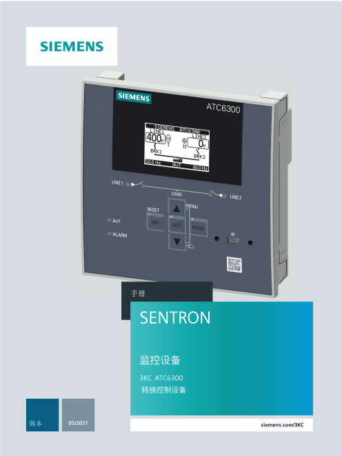
3KC ATC6300 自动转换控制器 设备手册说明书
4.5 4.5.1 4.5.2
ATC6300 的显示页面....................................................................................................30 显示页面说明 ...............................................................................................................30 滚动显示页面 ...............................................................................................................41
2.1
ATC6300 自动转换控制器的属性 ..................................................................................15
2.2
兼容的西门子 SENTRON 开关设备.................................................................................17
3.3
电压控制 ......................................................................................................................22
4 产品描述 .........................................................................................................................................25
麦克斯威尔RC6低轮廓绞车手册说明书

RC6 Low ProfileRC6 showing, ‘fast install’,in-line vertical gearboxand motor • The stainless steel (AISI 316) RC6 Series incorporates achromed bronze chainwheel suitable for use with 6 mm/7 mm(1/4”) chain spliced to 12 mm (1/2”) three strand or 8-brait(plait) rope.• T he RC6 features Maxwell’s revolutionary, and patented,Wave Design™ chainwheel. Refer below for more informationabout this innovative feature.• P roviding most of the features of the larger RC8 (refer pages286 - 287), the RC6 has been designed with the smaller, trailerboat market in mind.• T he in-line, vertical gearbox and motor means quick and easyinstallation by either the boat yard or the DIY aftermarket customer.• A n inexpensive, high performance and great looking windlass;the RC6 is built for durability and years of trouble free use.•T he RC6 is a Low Profile unit (no optional capstan drum).Features and benefitsImportant: Maxwell windlasses must be used in conjunction with a chainstopper or alternative snubbing device to take the load off the windlasswhile laying at anchor. The chain stopper and alternative snubbing systemshould also be used to secure the anchor in the fully raised position whileunder way.Every Maxwell RC6 automatic rope/chain windlass comeswith top works, gearbox, motor and dual direction solenoid.Switches and circuit breaker are available and need to beordered separately. Refer chart on page 314.STANDARD EQUIPMENT REQUIREDFOR DUAL DIRECTION CONTROLDual Direction Solenoid (included)Emergency ‘free fall’ activation lever (included)Up/Down remote control panel (not included)Circuit breaker/isolator panel (not included)OPTIONS1. AutoAnchor™ Equipment2. Compact Remote3. Foot Switches4. Chain Stopper5. Chain SnubberSPECIFICATIONSModel RC6Maximum Pull/Lift 350 kg770 lbsStatic Hold 700 kg1540 lbsChain Short Link 6 mm/7mm1/4”Rope Size (Nylon)* 12 mm(3 strand or 8 plait recommended)1/2”Chain Speed (Anchor Retrieval)24 m/min79 ft/minRope Speed (Anchor Retrieval)21 m/min69 ft/minPower Supply (DC)12 or 24 VMotor Power 500 WNet Weight 8.5 kg18.7 lbs* refer to owners manual for rope size variations.DIMENSIONSModel RC6A 196 mm7 3/4””B 80 mm3 3/16”C 145 mm5 3/4”D 209 mm8 1/4”E 65 mm2 1/2”F 39 mm1 9/16”RC6The stainless steel (AISI 316) RC6 automatic rope/chainanchor winch is Maxwell’s smallest version in the highlysuccessful vertical RC Series Windlass Range.MAXWELL’S REVOLUTIONARY CHAINWHEELMaxwell lead the market yet again in innovative thinking when they introducedthe Wave Design™ chainwheel. This patented rope/chain wheel incorporatestwo unique design concepts that greatly improve the handling and control of therope/chain spliced rode. The outer ribs of the chainwheel are angled slightlyforward ensuring that the rope and the chain are smoothly guided in the wheelduring anchor retrieval.As the rope pulls into the wheel, the opposite facing inner ribs grip the rope in anundulating manner, securing the rope more firmly in a ‘wave pattern’ action that isfar superior to the traditional ‘jam cleat’ manner of holding the rope comparedto all other products on the market. Not only does this Wave Design™ hold therope more securely, it is also kinder on the rope resulting in increased longevityof your anchor rode.Vertical Rope/Chain SeriesRC8 Low Profile VersionMcLAY BOATS’ 690RC8 with gearbox and motor• U nique spacer tube design allows installation through virtuallyany deck thickness and the multiple mounting positions and selfaligning gearbox ensure optimal location of gearbox and motorin virtually all installation situations.• T he RC8 features Maxwell’s revolutionary, and patented,Wave Design™ chainwheel. Refer RC6 page 285 for moreinformation about this innovative feature.• T he heavy duty stainless steel (AISI 316) pressure arm isdesigned to effectively help grasp the rope/chain splice, givingthe RC8 an unparalleled level of performance. In combinationwith a heavy duty, large wire diameter, stainless steel pre-loaded spring, the pressure arm always exerts maximum controlpressure.• T he RC8 works just as effectively with all-chain rodes.• H uge, through deck hawse pipe throat ensures easy entry ofthe rope/chain rode into and out of the anchor locker.• Full disassembly capability of the topworks utilisingonly the handle provided and an Allen key.• Manual override and ‘Free Fall’, using theemergency crank/clutch handle provided.• S ealed oil bath and marine-gradehard anodised, alloy gearbox providesmaximum output via a precision wormand worm wheel.Features and benefits• T he stainless steel (AISI 316) RC8-6 Series incorporates a chromed bronzechainwheel, designed to effortlessly retrieve and deploy 6 mm/7 mm (1/4”) chainspliced to 12 mm (1/2”) three strand or 8-brait (plait) rope.• T he more powerful RC8-8 can be used with 8 mm (5/16”) chain spliced to16mm (5/8”) three strand or 8-plait rope.• T he ingenious Wave Design™ rope/chain gypsy (chainwheel) is able toaccommodate a wide range of chain pitch differences within the specifiedchain size diameters suitable for use with the RC8 Series.• A sleek, Low Profile version and a fluted stainless steel capstan drum version,are available.• S imple two piece installation saves time and money and allows easy retrofittingwithout disassembly of the windlass.Vertical Rope/Chain Series SPECIFICATIONSModel RC8 (6/7 mm-1/4”) RC8 (8 mm-5/16”)Maximum Pull/Lift 350 kg 600 kg770 lbs 1320 lbsStatic Hold 1200 kg 1200 kg2640 lbs 2640 lbsChain Short Link 6 mm/7mm 8 mm1/4” 5/16”Rope Size (Nylon)* 12 mm 14 mm-16mm(3 strand or 8 plait recommended)1/2” 9/16”-5/8”Chain Speed (Anchor Retrieval)28 m/min 32 m/min92 ft/min 105 ft/minRope Speed (Anchor Retrieval)24 m/min 28 m/min79 ft/min 92 ft/minPower Supply (DC)12 or 24 V 12 or 24 VMotor Power 600 W 1000 WNet Weight 12.5 kg 16.5 kg27.5 lbs 36.3 lbs* refer to owners manual for rope size variations.DIMENSIONSBoth Models RC8 (6/7 mm-1/4”) RC8 (8 mm-5/16”)A 210 mm 210 mm8 5/16” 8 5/16”B1 83 mm 83 mm3 5/16” 3 5/16”B2 (with Capstan)146 mm 146 mm5 3/4” 5 3/4”C 156 mm 156 mm6 3/16” 6 3/16”D 200 mm 208 mm7 7/8” 8 1/4”E 245 mm 272 mm9 5/8” 10 3/4”F 383 mm 410 mm15” 16 1/4”G (Std deck clearance) ^65 mm 65 mm2 1/2” 2 1/2”H 40 mm 40 mm1 5/8” 1 5/8”I 66 mm 66 mm2 5/8” 2 5/8”J 44 mm 44 mm1 3/4” 1 3/4”^ extra deck clearance models available. Contact your Maxwell dealer.RC8-6 • RC8-8Important: Maxwell windlasses must be used in conjunction witha chain stopper or alternative snubbing device to take the load off thewindlass while laying at anchor. The chain stopper and alternativesnubbing system should also be used to secure the anchor in the fullyraised position while under way.OPTIONS1. AutoAnchor™ Equipment2. Compact Remote3. Foot Switches4. Chain Stopper5. Chain Snubber6. Capstan modelThe stainless steel (AISI 316) RC8 Series of automaticrope/chain anchor winches are Maxwell’s mid-rangemodels in the highly success RC Series Windlass Range.Simple two piece installation STANDARD EQUIPMENT REQUIREDFOR DUAL DIRECTION CONTROLDual Direction Solenoid (included)Emergency crank/clutch release handle lever (included)Up/Down remote control panel (not included)Circuit breaker/isolator panel (not included)HEIGHT MATCHED CHAIN STOPPER• For use with Maxwell’s rope/chain vertical windlasses• Height adjusted to most effectively align chainwith the chainwheel• No height adjustment plinth required• Refer to page 309 for more informationHeight MatchedChain StopperEvery Maxwell RC8 automatic rope/chain windlass comes with the topworks, gear box, motor and dual-direction solenoid. Switches andcircuit breaker are available and need to be ordered separately.Refer chart on page 314.Features and benefits RC10 Low Profile VersionRC10 Capstan Version• The stainless steel (AISI 316) RC10-8 Series incorporates a chromed bronze chainwheel, designed to effortlessly retrieve and deploy 8 mm (5/16”) chain spliced to 14 mm (9/16”) or 16mm (5/8”) three strand or 8-brait (plait) rope.• The more powerful RC10-10 can be use with 10mm (3/8”) chain spliced to16 mm (5/8”) three strand or 8-brait (plait) rope.• A sleek, Low Profile version and a fluted stainless steel capstan drum version, are available.• S imple two piece installation saves time and money and allows easy retrofitting without disassembly of the windlass. Unique spacer tube design allows installation through virtually any deck thickness and the multiple mounting positions andself aligning gearbox ensure optimal location of gearbox and motor in virtually all installation situations.• F ull disassembly capability of the topworks utilising only the handle provided and an Allen key.• T he RC10 is manufactured from marine-grade 316 stainless steel andchromed bronze for long term durability. The heavy duty stainless steelpressure arm, coupled with the unique rope/chain gypsy, is designed toeffectively grasp the splice between rope and chain, giving the RC10 anunparalleled level of performance.• I n combination with a heavy duty, large wire diameter, stainless steel pre-loaded spring, the pressure arm pivots on a trouble free bearing, thereby exertingmaximum control pressure on the rode and splice.• T he RC10 works just as effectively with all chain rodes for those who desire aLow Profile, elegantly styled windlass on their foredeck.• H uge, through deck hawse pipe throat ensures easy entry of the rope/chainrode into and out of the anchor locker.• Cone type clutch/brake mechanism permits manual, ‘Free Fall’ anchoring.• S ealed oil bath and marine-grade hard anodised, alloy gearbox provides maximumoutput via a precision worm and worm wheel.Model RC10 (8 mm-5/16”) RC10 (10 mm-3/8”)Maximum Pull/Lift 700 kg 850 kg1540 lbs 1870 lbsStatic Hold 1500 kg 1500 kg3300 lbs 3300 lbsChain Short Link 8 mm 10 mm5/16” 3/8”Rope Size (Nylon)* 14 mm - 16 mm 16 mm(3 strand or 8 plait recommended) 9/16”-5/8” 5/8”Chain Speed 24 m/min 24 m/min(Normal Working load)79 ft/min 79 ft/minRope Speed 20 m/min 20 m/min(Normal Working load)65 ft/min 65 ft/minPower Supply (DC) 12 or 24 V 12 or 24 VMotor (Watts) 1000 W 1200 WNet Weight 19 kg 20 kg42 lbs 44 lbs* refer to owners manual for rope size variations.DIMENSIONSModel RC10 (8 mm-5/16”) RC10 (10 mm-3/8”)A 230 mm 230 mm9 1/8” 9 1/8”B1 89 mm 89 mm3 1/2” 3 1/2”B2 (with capstan) 168 mm 168 mm6 5/8” 6 5/8”C 170 mm 170 mm6 3/4” 6 3/4”D 251 mm 251 mm10” 10”E 272 mm 272 mm10 3/4” 10 3/4”F 424 mm 424 mm16 3/4” 16 3/4”G (Std deck clearance) ^ 100 mm 100 mm4” 4”H 43 mm 43 mm1 3/4” 1 3/4”I 66 mm 66 mm2 5/8” 2 5/8”J 44 mm 44 mm1 3/4” 1 3/4”^ extra deck clearance models available. Contact your Maxwell dealer.STANDARD EQUIPMENT REQUIREDFOR DUAL DIRECTION CONTROLDual Direction Solenoid (included)Emergency crank/clutch release handle lever (included)Up/Down remote control panel (not included)Circuit breaker/isolator panel (not included)OPTIONS1. AutoAnchor™ Equipment2. Compact Remote3. Foot Switches4. Chain Stopper5. Chain Snubber6. Capstan modelThe stainless steel (AISI 316) RC10 Series of automaticrope/chain anchor winches are Maxwell’s uppermid-range models in the highly successful RC SeriesWindlass Range.Important: Maxwell windlasses must be used in conjunction with a chainstopper or alternative snubbing device to take the load off the windlass whilelaying at anchor. The chain stopper and alternative snubbing system should alsobe used to secure the anchor in the fully raised position while under way.Every Maxwell RC10 automatic rope/chain windlass comes with topworks, motor/gear box and dual direction solenoid. Switches and circuitbreaker are available and need to be ordered separately. Refer chart onpage 314.HEIGHT MATCHED CHAIN STOPPER• For use with Maxwell’s rope/chain vertical windlasses• Height adjusted to most effectively align chainwith the chainwheel• No height adjustment plinth required• Refer to page 309 for more informationHeight MatchedChain StopperFeatures and benefits• T he RC12 fully automatic windlass series is designed to effortlessly retrieve and deploy 10 mm (3/8”) short link chain and 16 mm (5/8”) to 20 mm (3/4”) three strand or 8-Plait rope (RC12-10) and 13 mm (1/2”) short link chain and 16 mm (5/8”) to 20 mm (3/4”) three strand or 8-Plait rope (RC12-12).• Stainless steel AISI 316.• W ith a maximum pull of 1590 kg (3500 lb), and an anchor retrieval rate of 15 m/min (50ft/min), the RC12-12 is one of the fastest and gruntiest windlasses in its class.• A sleek, Low Profile version and a fluted stainless steel (AISI 316) capstan drum version, are available.• T he all new RC12 is packed with patented innovative features combined with Maxwell’s traditionally classic aesthetics, but reflecting the modern “form follows function” of the highly successful RC6, RC8 and RC10 series windlasses.• T he elegantly designed deckplate and chainpipe cover are manufactured in polished marine-grade (AISI 316) stainless steel,as are the heavy duty pressure arm, stripper, chainwheel and fluted capstan drum.• T he huge, through deck hawse pipe throat ensures easy entry of the rope/chain rode into and out of the anchor locker.• D ouble cone-type brake/clutch mechanism permits ‘Free Fall’ anchoring. Cone clutches, unlike dog clutches, provide smooth progressive engagement, ensuring safe and precise operator control.• T he RC12 features Maxwell’s revolutionary and patented new Wave Design™ chainwheel. Refer to RC6 page for more information about this innovative feature.• E mergency manual retrieval is made simple and easy with Maxwell’s unique “Active Latch Ratchet System” operation that prevents backwind of the windlass during manual hauling of the anchor.• T he Maxwell designed, all new and innovative black, hard anodised gearbox provides numerous advantages:- Fast and easy windlass installation- More corrosion resistant- Easy to maintain and service- Takes up less room in the anchor locker- 75:1 Ratio (RC12-10) or 100:1 Ratio (RC12-12), single stagedesign with less moving parts, for smoother and quieter operation - Allows for multi-positioning of the gearbox/motor.RC12 Low Profile ModelRC12 Capstan ModelActivation of the ratcheted mechanism lever ensures the windlass can not backwind during emergency (manual) retrieval of the rode (rope and/or chain) and anchor.SPECIFICATIONSModel RC12 (10/11 mm-3/8”) RC12 (12/13 mm-1/2”)Maximum Pull/Lift 1134 kg 1590 kg2500 lbs 3500 lbsStatic Hold 2200 kg 2200 kg4840 lbs 4840 lbsChain Short Link** 10/11 mm 12/13 mm3/8” 1/2”Rope Size (Nylon)** 16-20 mm 20 mm(3 strand or 8 plait recommended)5/8-3/4” 3/4”Chain Speed 20 m/min 15 m/min(at normal working load)65 ft/min 50 ft/minRope Speed 17 m/min 13 m/min(at normal working load)56 ft/min 43 ft/minPower Supply (DC)12 or 24 V 12 or 24 VMotor Power 1200 W 1200 WNet Weight - DC 32 kg 32 kg(Capstan version) 71 lbs 71 lbsNet Weight - DC 29 kg 29 kg(Low Profile version)64 lbs 64 lbsHydraulic Pressure 138 bar 138 bar2000 PSI 2000 PSIHydraulic Flow 42 l/min 42 l/min11USgal/min 11 USgal/minNet Weight - Hyd (Low Profile)23 kg/ 51 lbs 23 kg/ 51 lbs(Capstan version)26 kg/ 57 lbs 26 kg/ 57 lbs** When ordering please specify your specific rope and chain, combination rodeDIMENSIONSModel RC12 (10 mm-3/8”) RC12 (12/13 mm-1/2”)A 293 mm 293 mm11 5/8” 11 5/8”B1128 mm 128 mm(Low Profile version) 5 1/8” 5 1/8”B2233 mm 233 mm(Capstan version)9 1/4” 9 1/4”C 206 mm 206 mm8 1/8” 8 1/8”D 210 mm 210 mm(Std deck clearance)8 3/8” 8 3/8”E 294 mm 294 mm11 5/8” 11 5/8”F 482 mm 482 mm19” 19”G 90 mm 90 mm(Std deck clearance) 3 5/8” 3 5/8”H 54 mm 54 mm2 1/4” 2 1/4”I 106 mm 106 mm4 1/4” 4 1/4”J 62 mm 62 mm2 1/2” 2 1/2”OPTIONS1. AutoAnchor™ Equipment2. Compact Remote3. Foot Switches4. Chain Stopper5. Chain Snubber6. Capstan modelThe RC12 Series incorporates Maxwell’s latest stylish innovation in automatic rope/chain windlass technology. Retaining the classic open design styling more appropriate on larger boats, the RC12-10 and RC12-12 represent the next generation of rope/chain windlass evolution in every respect.Important: Maxwell windlasses must be used in conjunctionwith a chain stopper or alternative snubbing device to take the load offthe windlass while laying at anchor. The chain stopper and alternative snubbingsystem should also be used to secure the anchor in the fully raised position while under way.STANDARD EQUIPMENT REQUIREDFOR DUAL DIRECTION CONTROLDual Direction Solenoid (included)Emergency (manual) retrieval handle (included)Clutch release handle (included)Up/Down remote control panel (not included)Circuit breaker/isolator panel (not included)Every Maxwell RC12 automatic rope/chain windlass comes with top works, motor/gearbox and dual direction solenoid. Switches and circuit breaker are available and need to beordered separately. Refer chart on page 314.HEIGHT MATCHED CHAIN STOPPER• For use with Maxwell’s rope/chain vertical windlasses• Height adjusted to most effectively align chainwith the chainwheel• No height adjustment plinth required• Refer to page 309 for more informationHeight MatchedChain Stopper。
- 1、下载文档前请自行甄别文档内容的完整性,平台不提供额外的编辑、内容补充、找答案等附加服务。
- 2、"仅部分预览"的文档,不可在线预览部分如存在完整性等问题,可反馈申请退款(可完整预览的文档不适用该条件!)。
- 3、如文档侵犯您的权益,请联系客服反馈,我们会尽快为您处理(人工客服工作时间:9:00-18:30)。
6.0
7.0
For performance information in a vacuum or with hot side temperatures other than 27°C or 50°C, consult one of our Applications Engineers.
Installation
214-340-4900 (tel) ● 214-341-5212 (fax) ●
Doc # 102-0284
Rev A
Page 2 of 2
Addresses
Marlow Industries, Inc. 10451 Vista Park Road Dallas Texas 75238-1645 214-340-4900 (tel) 214-341-5212 (fax) Marlow Industries Europe Aberdeen House, South Road Haywards Heath West Sussex RH164NG UK +44 (0)1444-443404 (tel) +44 (0)1444-443334(fax) Marlow Industries Japan 1-1-8-401 Uehara, Shibuya-ku Tokyo, Japan 151-0064 +81 (3) 5454-5280 (tel) +81 (3) 5454-5281(fax)
.787 [19.9]
.965 [24.5]
_
COLD SIDE, Tc
-01, -01S .003 [0.08] .002 [0.05]
-01L, -01LS .002 [0.05] .001 [0.03] A
.002 [0.05] HOT SIDE, Th -01 & -01S -01L & -01LS .158±.005[4.01±0.13] .154±.001[3.91±0.03] Ceramic Material: Alumina (AC) A
.001 [0.03]
Dimensions in [ ] are millimeters
Ordering Options
Model Number RC3-6-01 RC3-6-01L RC3-6-01S RC3-6-01LS Description Base Model w/ leads Lapped Model Sealed Model Lapped and Sealed Model
Page 1 of 2
214-340-4900 (tel) ● 214-341-5212 (fax) ●
元器件交易网
marlow
industries
Subsidiary of II-VI Incorporated
a global leader in thermoelectric solutions
RoHS 2002/95/EC Compliant
Mechanical [19.9]
+
MARLOW RC 3-6 L 123456
POSITIVE LEAD (WHITE) .30±.25 [7.62±6.35] 20 AWG LEADS, TEFLON INSULATED NEGATIVE LEAD (BLACK) 4.00 ±.50 [101.6 ± 12.7]
Performance Curves
Environment: One atmosphere dry nitrogen
Hot Side Temperature: 27°C
TA(C)= 27 80.0 HEAT LOAD (WATTS) 0.00 1.00 2.00 3.00 4.00 5.00 6.00 7.00 8.00 9.00 10.0 11.0 12.0 80.0
Hot Side Temperature: 50°C
TA(C)= 50 HEAT LOAD (WATTS) 0.00 1.00 2.00 3.00 4.00 5.00 6.00 7.00 8.00 9.00 10.0 11.0 12.0 13.0
60.0 T (C)
60.0 T (C) VOLTAGE (VDC)
Hot Side Temperature (°C) ∆ Tmax (°C-dry N2): Qmax (watts): Imax (amps): Vmax (vdc): AC Resistance (ohms): 27°C 65 13 5.6 3.6 0.5 50°C 73 14 5.6 4.1 ---
元器件交易网
marlow
industries
Subsidiary of II-VI Incorporated
a global leader in thermoelectric solutions
Thermoelectric Cooler RC3-6
Performance Values
Operation Cautions
For maximum reliability, storage and operation below 85°C in a non-condensing environment is recommended. To minimize thermal stress, use linear/proportional temperature control or a similar method rather than an ON/OFF method.
Features
• • • • • • • • RoHS 2002/95/EC compliant Solid-state reliability. Built with high temperature solder with the ability to withstand higher assembly processing temperatures for short periods of time (<160°C). Superior nickel diffusion barriers on elements High strength for rugged environment. Porched configuration for enhanced leadwire strength RTV sealing available (Optional) Lapped option available for multiple module applications. Doc # 102-0284 Rev A
40.0
40.0
20.0
20.0
0.0 4.0 VOLTAGE (VDC) 3.0 2.0 1.0 0.0 0.0
0.0 4.0 3.0 2.0 1.0 0.0 0.0
Q=0 T=0
Q=0 T=0
1.0
2.0 3.0 4.0 5.0 CURRENT (AMPS)
6.0
7.0
1.0
2.0 3.0 4.0 5.0 CURRENT (AMPS)
Recommended mounting methods: Bonding with thermal epoxy or soldering with metallized ceramics. For additional information, please refer to our TEC Installation Guide.
