An asynchronous switching high-end power amplifier
abb变频器(Abbinverter)

abb变频器(Abb inverter)ABB inverter is a well-known frequency converter brand developed, produced and sold by ABB group. Is mainly used to control and adjust the speed of three-phase ac asynchronous motor, and the combination of its stable performance, rich functions, high performance of vector control technology, high torque output at low speed, good dynamic characteristics and strong overload capacity, occupying the important status in the inverter market.directoryBrand introductionCommon type ACS 2000The ACS 510The service life of theThe working principle ofCommon fault failureOverload faultBrand introductionCommon type ACS 2000The ACS 510The service life of theThe working principle ofCommon fault failureOverload faultThe development of the brand introduced ac inverter to control the speed and torque of the standard induction motor, abb inverterThe standard induction motor is the main equipment in the industrial field. ABB is the market leader in the field of global frequency conversion controllers and motors. Ac frequency conversion technology extends the speed range of the motor - from zero to far above the rated speed - so that the production efficiency of the drive process is significantly improved. In the case of a low capacity, the converter saves energy by reducing the motor speed. [1] ABB standard frequency converter is simple to purchase, install, set up and use, saving a lot of time. They are widely available at ABB's distributors and are thus called standard frequency converters. This type of converter has a common customer and process interface with the fieldbus, specification design, debugging and maintenance of common software tools, and general spare parts. Edit this section common type ACS 2000Air cooling type ACS 2000 inverter in cement, mining and mining, metallurgy, pulp and paper, water, electricity and chemicalindustry, petroleum and natural gas industries such as fan, pump, compressor and other public application. ACS 2000 frequency converter combined with innovative technology, in order to cope with the challenge of the industry, such as the flexible power supply connection, lower harmonic, reducing energy consumption, static reactive power compensation as well as the need of installation and debugging. Flexible power supply connection ACS 2000 frequency converter can not use input isolation transformer, depending on the user's choice and the situation of the existing equipment, thus allowing direct connection to the power supply (direct grid connection), or can be connected to an input isolation transformer. Under the direct power grid connection configuration, users can benefit from lower investment costs because they do not need a transformer and can save a large amount of investment. ACS 2000 inverter compact structure, lighter weight, and lower transportation costs compared with other inverters that require transformers, and require less space in the electrical room. From the compact design, the ACS 2000, which connects directly to the 6.0-6.9 kV power grid, is applicable to the modified project of the standard induction motor for speed control. In need to match or voltage power supply for electrical isolation of applications, the input transformer is needed, the ACS 2000 frequency converter can be connected to the conventional double winding oil-immersed or dry input isolation transformer. Lower harmonic integrated the technologies of active front-end (AFE), without using expensive, special transformer, power grid side harmonic can be minimized, and four quadrant operation as well as the additional benefits of reactive power compensation. The AFE provides low harmonics and satisfies the requirements ofcurrent and voltage harmonics in various standards. Thus, there is no need for harmonic analysis or installation of mesh side filters. In order to minimize energy consumption, the AFE allows four quadrants to operate and return the braking energy back to the grid. Reactive power compensation AFE can also provide reactive power compensation. With static reactive power compensation, the smooth power grid voltage can be maintained and no reactive power penalty can be avoided. Installation, debugging and operation and maintenance are convenient for the installation and commissioning of the installation and debugging. Install a converter,Using ABB's simple concept of "three to three" wiring, simply disconnect the cable running directly from the network, connect to the converter, and then connect the converter to the motor. The ACS 2000 design has an extractive phase module to facilitate quick replacement of all frequency converter components from the front, and the average maintenance time (MTTR) is the industry-leading level. High reliability The converter using the validated multilevel voltage source inverter (VSI) topology structure, mature high voltage IGBT power semiconductor technology and direct torque control (DTC) motor control platform, so it is of high reliability, extend the MTBF (MTBF) and increases the utilization. The ACS 2000 inherited the VSI topology structure of the ABB and adopted the patented, multilevel design based on IGBT, provides approximate sine wave current and voltage waveform, makes the inverter is compatible with standard motor and cable. The ACS 2000 converter control platform USES ABB's highly acclaimed DTC platform, which provides the maximum torque and speed performance and minimal loss of the medium voltage ac converter. Under all conditions,the control of inverter is fast and smooth. Lower total cost of investment and flexible power supply connection, lower harmonic and energy consumption, ease of installation and debugging and higher reliability, makes the ACS 2000 throughout the life cycle with low total cost of investment. [2]The ACS 510ACS510 is another outstanding low voltage ac drive product from ABB. The ACS510 can be simple to purchase, install, configure, and use, saving a considerable amount of time. Application: ABB drive is applied to industrial area. ACS510 is especially suitable for fan pump transmission. Typical applications include constant pressure water supply, cooling fan, subway and tunnel ventilator, etc. Highlights: 1. Perfect matching fan pump application; 2. Advanced control panel; 3. Patented technology used to reduce harmonics; Variable inductor; 4. Cycle soft; 5. Multi-point U/F curve; 6. Transcendental mode;7. The built-in RFI filter is used as standard configuration for the first and second environments; The main performance of CE certification: perfect matching fan pumps: enhanced PFC applications: up to 7 (1 + 6) pumps; Can switch more pumps. SPFC: cycle soft function; Each pump can be adjusted in turn.Multi-point U/F curve: can be free to define 5 points U/F curve; Flexible and wide application. Supermodel: fire mode applied to tunnel fan; Apply to emergency situations. PID regulator: two separate built-in PID controllers: PID1 and PID2, PID1 can set two sets of parameters; A separate external valve can be controlled by PID2. More economical: intuitive characteristics: noise optimization, when the transmission temperature decreases, increase the switching frequency, controllablecooling fan, only when needed; Random distribution switch frequency can reduce noise, greatly improve motor noise, reduce transmission noise and improve efficiency. Magnetic flux optimization: automatic reduction of motor flux when load decreases; It greatly reduces energy consumption and noise. Connectivity: simple installation, can be installed side by side, easy to connect cables, easy connect to the field bus system through multiple I/O connections and plug-in optional pieces; Reduce installation time, save installation space, reliable cable connection. More environmentally friendly: EMC: the RFI filter for the first and second environment is standard; No additional external filters are required. Reactance: variable inductor: according to different load matching inductance, the harmonics are suppressed and reduced. Lower total harmonic other: advanced control panel: 2 function keys, function changes with different state, built-in help key, modified parameter list; Easy to configure and debug, fast start, fast entry parameters. Fieldbus: built-in RS485 interface, using Modbus protocol,The plug-in field bus module is optional; It reduces the cost. Edit this paragraph 1, the electromagnetic interference on the influence of the frequency converter service life In modern industrial control system, using microcomputer and PLC control technology, in the process of system design or renovation, it is important to note that frequency converter to the problem of the interference of the microcomputer control board. Inverter by the interference source as shown in figure 1, due to the user's own design of microcomputer control board general technological level is poor, do not conform to the EMC international standards, after using frequency converter, theconduction and radiation interference, often leads to abnormal control system, so you need to take the following necessary measures. 1) good grounding. The grounding wires of the power control system such as the electric motor must be reliably grounded through the grounding bus, and the microcomputer control panel should be grounded separately. For some serious disturbances, it is recommended that the sensor, I / 0 interface shield layer be connected to the control of the control panel.2) EMI filter, common mode inductance and high frequency magnetic ring can be used to input power supply of microcomputer control board. In addition, if there is a GSM, or a little lingtong base station in the vicinity, the microcomputer control board can be shielded from the metal mesh shield. 3) to the inverter input with EMI filter, can effectively restrain the conduction interference frequency converter to the grid, reactor with ac and dc input, can improve the power factor, reduce the harmonic pollution, comprehensive effect is good. In some places of more than 100 m distance between the motor and inverter, need adding in the inverter side ac output reactor, solve because the output wire of distribution parameters caused by the leakage current protection, and reduce the radiation of external interference. An effective way to do this is to use steel tube threading or to block the cable, and to connect the steel tube casing or cable shield to the earth. It is worth noting that if the method of tube threading or shielding cable is used to avoid the addition of ac output reactor, the distribution capacitance of the output to the ground is increased, and the flow is easy to occur. In practice, of course, one or several methods are generally adopted. 4) electrical shielding and isolation for analog sensor detection input and analog control signals. In the design of the control systemcomposed of frequency converter, it is recommended that the simulation control should not be adopted, especially if the control distance is greater than 1m and the control cabinet is installed. Because the frequency converter has a multi-speed setting, switching frequency input output, can meet the requirements. If it is necessary to control the analog quantity, it is recommended that the shielded cable should be used, and the side of the sensor side or the converter side will be further grounded. If the interference is still serious, you need to implement DC/DC isolation measures. A standard DC/DC module can be used, or a v/f conversion light isolation is adopted, and a frequency setting input method is adopted. 2. The influence of working environment is in the actual application of inverter. Since domestic customers have only a few special-purpose machine rooms, most of them have been installed in the industrial site to reduce the cost. The job site is usually dusty, high temperature and humidity, as well as metal dust and corrosive gases in the aluminum industry. Accordingly, the corresponding countermeasures must be made according to the situation, as shown in figure 2. 1) the frequency converter should be installed inside the control cabinet. 2) the converter is best installed in the middle of the control cabinet; The frequency converter should be installed vertically, and the upper and lower parts should avoid the big elements that may block the wind and wind. 3) the minimum distance between the control cabinet top, bottom, or the partition, or the large element that must be installed, should be greater than 300 mm.4) if you need to take off in particular users in the use of the keyboard, the frequency converter panel keyboard holes, must use tape seal or is strictly false panel replacement, prevent the dust into the converter internal a lot. 5) whenusing the frequency converter in the multi-dust area, especially in the place where the multi-metal dust and floccus are used, the overall control cabinet shall be sealed in a whole.Specially designed the inlet and outlet for ventilation; The top of the control cabinet should have a protective net and a cover outlet. The bottom of the control cabinet should have the bottom plate and the inlet, the inlet hole, and install the dustproof net. 6) most of the frequency converter manufacturers within the PCB, metal structure failed to prevent mildew damp special processing, if the inverter under bad working environment for a long time, metal structure prone to rust. In the case of high temperature operation, the conductive copper can aggravate the process of corrosion. For the microcomputer control board and the small copper conductor on the power supply board, the rust will cause damage. Therefore, for applications in humid and containing corrosive gas, must have the basic request for the interior design of frequency converter used, such as printed circuit board must use anti-corrosion paint spraying process, nickel chromium plating process must be used for structural. In addition, it is necessary to take other active, effective and reasonable measures against damp and anti-corrosive gases. The influence of the quality of the power grid on the frequency converter, such as welder, arc furnace, rolling mill, etc. In a shop, there are many sets of frequency converter and other capacitive rectifier load at work, the harmonic produced very serious pollution on the grid quality, also have considerable damage to the equipment itself, the light will not be able to run normally, consecutive or causes the damage of equipment input circuit. The following measurescan be taken. 1) in the case of shock load such as welder, arc furnace and rolling mill, it is recommended that users add reactive static devices to improve power factor and quality of power grid. 2) in the workshop where the frequency converter is more concentrated, it is recommended to use centralized rectifier, dc common bus supply mode. It is recommended that users adopt a 12-pulse rectification mode. The advantages are harmonic small, energy saving, especially suitable for frequent starting and braking, the motor is in both electric operation and power generation operation. 3) inverter input side add passive LC filter, reduce input harmonic, improve power factor, high reliability, good effect. 4) the converter input side loading has the source PFC device, the effect is best, but the cost is higher. Edit this section of the works by using a 380 v ac voltage rectifier filter become smooth dc voltage is 510 v, and then through the inverter device 510 v dc voltage into frequency and voltage adjustable alternating voltage, voltage regulating range is between 0 v - 380; Frequency adjustable range between 0HZ -- 600HZ. In order to control the speed of the electric motor. The common fault in this section is overflowedOver-current failure can be divided into the acceleration, deceleration, constant speed over current. It may be due to the frequency converter of deceleration time is too short, load mutation, uneven distribution of the load, output short circuit caused by waiting for a reason, then through prolonged deceleration, the general can reduce the load of the mutation, and energy consumption braking components, load distribution design, inspection on line, if you disconnect the load frequency converter or over current fault, inverter invertercircuit has been ring, need to replace the frequency converter. Overload faultOverload failure including inverter overload and electric machine overload, it may be accelerating time is too short, large amount of direct current braking, power grid voltage is too low, the heavy load such as the cause, generally can be lengthened by acceleration time, braking time, check the power grid voltage, etc., under the heavy load, the selected motor and frequency converter can't drag the load, also may be caused by mechanical lubrication is not good, such as the former must replace the high power motor and frequency converter; The latter, for example, must repair the production machinery.。
Asynchronous transfer mode
Asynchronous transfer mode(ATM)Asynchronous transfer mode (Asynchronous Transfer Mode, the abbreviation for ATM), also called relay information element. Asynchronous transfer mode (ATM) in ATM reference mode consists of a set of protocols. ATM Exchange with connection-oriented, it is in a cell. Each cell length 53 bytes. Which account for 5-byte header. Information element relay (cell relay) of a standard (ITU) implementation of program, this is a fixed-length packet (information) of Exchange technology. Is referred to as asynchronous, because from a user, contains information element to appear is not a cyclical.异步传输模式(缩写为ATM)也叫中继元信息传输,他是由一系列的程序组成的。
异步传输与面向连接传输在一个单元里转换,每个单元有53个字节,其中有5个字节起作用中继元信息传输是以固定长度的数据包技术交换实现的。
它之所以被称为异步传输是因为无论从使用还是信息元素都不在一个周期内。
ATM (Asynchronous Transfer Mode, asynchronous transfer mode a way to pass a comprehensive business information on high speed, high efficiency, control of flexible, innovative information transfer mode, has been ITU-T (International Telecommunication Union T elecommunication Standardization sector) to transfer and exchange of voice. Images, data and multimedia information tools, people's attention, is today one of the hot topics of information exchange. The birth of ATM technology has its inevitability, with the advent of the information society, people on communication needs are far beyond the traditional telephone and telegraph services, data communications, broadband communications, demand is increasing, due to their bandwidth and traffic requirements, the traditional means of communication have been very difficult to achieve. For example, the existing network are designed for a specific business, often do not apply to other business: CNN cannot transfer telephone service, telecom network cannot transmit TV signals. Obviously these networks to support new business capacity is not enough. It is hoped that in future, it is best to only one network exists, it is not dependent on the business, with the flexibility, security, economic and efficient use of all resources, ATM technology is considered implementation of key technologies.ATM(异步传输模式)是一种高速.高效.高灵活度.高创新度的综合信息传输模式,他被国际信联认定为传输声音图像和多媒体的工具,他已经成为一个备受人们关注的热门话题。
专业英语_考查试题
D. the number of binary bits
10. When an induction motor with 10 poles is supplied by 50Hz three-phase ac power source, the synchronous revolutions per minute is _____. (Synchronous r/min =120 f/p)
7. The north pole of the armature is attracted to the south pole of the main field. The south pole of the armature is attracted to the north pole of the main field._____
5. In alternating current an AC generator is used to make electrons flow continuously in one direction._____
6. InChinaalternating current is usually generated at 60Hz._____
A. digital form B. numerical form
C. binary form D. analog form
9. The precision of ADC ( analog-to-digital conversion ) is determined by _____.
A. its speedB. its gain
A. a digitalB. an analog
通信英语(翻译短文)

1.If we consider binary transmission, the complete information about a particular message will always be obtained by simply detecting the presence or absence of the pulse. By comparison, most other forms of transmission systems convey the message information using the shape, or level of the transmitted signal; parameters that are most easily affected by the noise and attenuation introduced by the transmission path. Consequently there is an inherent advantage for overcoming noisy environments by choosing digital transmission.研究二进制信号的传输可见,只要简单的区判别脉冲的有和无,完美就获得了一条消息的全部信息。
相比之下,许多其他形式的传输系统是利用被传信号的波形或电平的高低来传送信息的,而这些参数又极易受到传输途径中的噪声和衰耗的影响。
因此选择数字传输系统在克服噪声环境的影响方面有其固有的优势。
2.The reader may ask, how does the demultiplexer know which group of 8-digits relates to channel 1,2, and so on? Clearly this is important! The problem is easily overcome by specifying a frame format, where at the start of each frame a unique sequence of pulses called the frame code, or synchronization word, is placed so at to identify the start of the frame. A circuit of the demultiplexer is arranged to detect the synchronization word, and thereby it knows that the next group of 8-digits corresponds to channel 1.读者也许会问,分路设备怎么会知道哪一组8位码对应于第1路、第2路及其他各路呢?显然这是很重要的。
tny175pn
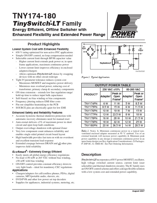
automatic recovery eliminates need for manual reset • Auto-restart delivers <3% of maximum power in short
circuit and open loop fault conditions • Output overvoltage shutdown with optional Zener • Very low component count enhances reliability and
enables single-sided printed circuit board layout • High bandwidth provides fast turn on with no overshoot
and excellent transient load response • Extended creepage between DRAIN and all other pins
improves field reliability
EcoSmart®– Extremely Energy Efficient • Easily meets all global energy efficiency regulations • No-load <150 mW at 265 VAC without bias winding,
Description
TinySwitch-LT incorporates a 650 V power MOSFET, oscillator, high voltage switched current source, current limit (user selectable) and thermal shutdown circuitry. The IC family uses an ON/OFF control scheme and offers a design flexible solution with a low system cost and extended power capability.
通信常用缩略语
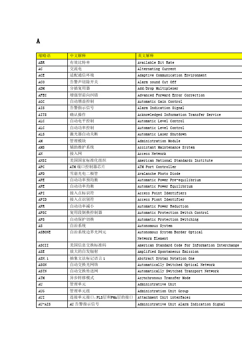
异步转移模式
Asynchronous Transfer Mode
AU
管理单元
Administrative Unit
AUG
管理单元组
Administration Unit Group
AUI
连接单元接口,PLS层和PMA层的接口
Attachment Unit interfaces
AU-AIS
AU告警指示信号
DCF
色散补偿光纤
Dispersion Compensation Fiber
DCG
色散补偿光栅
Dispersion Compensation Grating
DCM
色散补偿模块
Dispersion Compensation Module
DCN
数据通信网
Data Communication Network
ALC
自动电平控制
Automatic Level Control
ALC
自动功率控制
Automatic Level Control
ALS
激光器自动关断
Automatic Laser Shutdown
AM
管理模块
Administration Module
AMS
辅助维护系统
Assistant Maintenance System
AU Pointer Positive Justification
AUG
管理单元组
Administration Unit Group
AUP
管理单元指针
Administration Unit Pointer
AWG
阵列波导光栅
Arrayed Waveguide Grating
海尔电子洗衣机产品说明书

Section 6: Parts DataDC50X264310131211216547Cabinet GroupKey Part Number Description Quantity * 9960-285-008Door Assy., Loading Complete-Wht (2)* 9960-285-011Door Assy., Loading Complete-SS (2)* 9960-285-007Door Assy., Loading Complete-Chrome/BLK/SS (2)1 9960-284-002Door Assy., Loading-SS(ring only) (2)1 9960-284-004Door Assy., Loading-Chrome(ring only) (2)2 9982-353-002Plate Assy., Hinge (Wht) No Pin (2)2 9982-353-001Plate Assy., Hinge (SS) No Pin (2)* 9545-012-015Screw, Hinge to Door (8)* 8640-413-002Nut, Hinge to Door (8)3 9212-002-004Glass, Door (2)4 9206-413-002Gasket, Glass Black (2)* 9548-117-000Support, Door Glass (2)5 9206-420-005Gasket, Outer Rim Black (2)6 9244-082-001Handle, Loading Door (2)* 9545-018-017Screw, Handle 1/4-20 x 3/8 (4)* 9531-033-003Stud, Door Catch (2)* 8640-413-001Nut, Hex (2)* 8640-413-003Nut, Acorn (2)* 9086-015-002Catch, Loading Door (2)* 8638-190-009Pop Rivet for mtg. catch (4)* 8641-582-006Lockwasher (4)* 8640-399-001Spring Nut (6)7 9989-521-003Panel Assy., Front- Lower (Wht) (1)7 9989-521-001Panel Assy., Front- Lower (SS) (1)8 9989-517-003Panel Assy., Front- Upper (Wht) (1)8 9989-517-001Panel Assy., Front- Upper (SS) (1)* 9277-054-001Insulation Front Panel, half moon (top) (2)* 9277-054-002Insulation Front Panel, half moon (bottom) (2)9 9545-008-014Screw, FLHDCR, 10B x 1 (14) (6)* 8641-585-001 Lockwasher* 8640-399-001Nut, Spring (12)10 9544-069-002Strap, Hinge (Wht) (2)10 9544-069-005Strap, Hinge (SS/Black) (2)* 9545-012-028Screw, Hinge to Panel (8)11 9545-052-001Screw, Door to Hinge Strap (Special Black Type) (2)12 8641-436-003Washer, Fiber (2)13 9021-041-001Acceptor, Coin (1)* 9486-149-001Retainer, Coin Acceptor (2)14 9545-053-002Screw (4)* 9801-099-001Switch, Optical (1)Cabinet Group ContinuedKey Part Number Description Quantity15 9994-032-001Escutcheon, Upper (1)16 9435-039-002Trim, Overlay-Upper Blue (1)16 9435-039-001 Trim, Overlay-Upper Black (1)17 9994-033-001Escutcheon, Lower (1)18 9435-023-001Trim, Overlay-Lower Blue (1)18 9435-031-001Trim, Overlay-Lower Black (1)* 9545-020-009Screw (20)19 9412-167-002Nameplate Stack Dryer Express Blue (1)19 9412-167-001Nameplate Stack Dryer Express Black (1)20 9866-005-001Lint Drawer Assembly Blue (2)20 9866-005-004Lint Drawer Assembly Black (2)21 9435-024-001Overlay Trim, Lint Drwr-Blue (1)21 9435-032-001Overlay Trim, Lint Drwr-Black (1)* 9532-074-003Felt Seal ( back of lint screen assembly ) (2)* 9805-033-002Lint Screen Assembly ONLY (no front) (2)* 9555-057-008Replaceable Lint Screen Only (2)22 8650-012-004Lock and Key, Lint Drawer (2)* 6292-006-010Key 6101 only (2)* 9095-043-001Cam, Lock (2)* 9545-008-001Lint Screen Strap Hold Down Screws 10Bx 1/4 (32)23 9857-198-001Controls Assy, Blue (1)23 9857-198-003Controls Assy, Black (1)* 9627-869-001Harness, Electronic Control (1)24 8650-012-003Lock and Key, Control (1)* 9095-041-001Cam, Lock (1)* 6292-006-007Key only 6324 (1)* 9627-855-003Harness, Heat Sensor (1)* 8640-276-002Wire Nut Connector Grey (4)25 9501-004-003Sensor Temp Control (2)26 9501-008-001Bracket for Heat Sensor Mounting (Under Basket) w/ sensor..2* 9545-045-005Screw, Round Head (Mounts sensor; phillips head) (2)* 9209-037-002Gromm.et, 3/16 ID (2)* 8544-006-001Leg, Leveling 1/2” (4)* 9074-320-001 Cover, Cabinet (Top) (1)* 9277-041-017 Insulation Cabinet Cover (1)* 9732-276-001Kit for Dryers without Neutral and using 208-240 volt (1)* 9732-102-013LP Kit for 50Lb Stk Dryers (1)* 9732-243-001Stack Dryer Trunion Puller (1)* 9544-041-002 Strap - Bead Tie (1)27 9942-038-005 Vault, Coin Box (1)* 9545-008-024 Screws, Mounting-Coin Vault (2)28 9897-099-002 Coin Box Assy, Large Blue (1)28 9807-099-004 Coin Box Assy, Large Black (1)191526252792531089Control Parts GroupKey Part Number Description Quantity * 9857-198-001Controls Assy, Electronic Mounted With Membrane Switch, BLU (1)* 9857-198-003Controls Assy, Electronic Mounted With Membrane Switch, BLK (1)1 9826-008-001 Trough Assembly (1)2 9032-062-002 Button-Push, Control, Blue (2)2 9032-062-001 Button-Push, Control, Black (2)3 9538-166-011Spacer-Metal, 4mm (4)4 9486-158-001 Retainer-Push Button (2)5 8640-424-002Nut-Hex, Elastic stop, #4-40 (4)6 8652-130-038Terminal-Grounding clip (1)7 9534-365-001Spring-Flat, Control (1)8 9545-008-001Screw-Hex, #10B x 1/4 (2)9 9545-044-010 Screw-Hex, #10B x 1/4 (10)9 8641-582-005Washer-External tooth, #6 (10)10 9435-038-001Overlay-Control, Coin, Black (1)10 9435-038-002Overlay-Control, Coin, Blue (1)11 9021-041-001Acceptor-Coin, Optical (1)* 9486-149-001Retainer, Coin Acceptor (1)12 9545-053-002Screw (4)* 9801-099-001 Optical Sensor, Replacement (1)Note: Jumpers required if using 1.5 Control on Older Machines (P9 Connection)* 8220-155-001 Wire Assy, Jumper, 30Lb Stack Coin (1)* 8220-155-002 Wire Assy, Jumper, 50Lb Stack Coin (1)Door Switch GroupPart NumberDescription Quantity9539-487-001Door Switches (2)Hinge Plate Cover1 9074-340-002 Cover-Hinge, Black .....................................................................22 8636-008-010 Screw-TRHDCR, 10B x 3/8, Black.. (4)12Bearing Housing GroupKey Part Number Description Quantity J1 9241-189-002 Housing, Bearing (2)J2 9036-159-003Bearing, Ball Rear..................................................................... .2 * 9538-183-001 Spacer, Bearing (2)* 9036-159-001Bearing, Ball Front .................................................................... .2 J5 9545-017-017Bolt, 1/2 x 3/4 . (8)J7 8640-417-002Nut, 1/2 (8)* 9803-201-001Bearing Housing Complete Ass’y (includes bearings,spacer) (2)J4 9545-017-018Screw 1/2 x 1 1/2 (4)Burner Housing GroupKey Part Number Description Quantity * 9803-207-001 Housing Assembly, Burner (2)1a 9452-730-001Service Burner Plate Front... (2)1 9452-729-001 Service Plate baffl e Recirculation Chamber Clean Out (2)* 9545-008-006Screws (8)2 9545-008-001Screw (16)18 9003-220-001Angle, Burner Support (2)* 9545-008-006Screw (4)17 9048-020-002Burner, Main (4)* 9545-008-006Screw 10AB x 3/8” (4)* 9454-824-001 Panel, Back Burner Housing (2)4 9545-008-001Screw 10B x1/4” (8)5 9875-002-003Electrode Assy, Ignition (2)19 9545-045-001Screw, Electrode Mtg 8B x 1/4” (4)7 9379-186-001Valve, Gas Shut Off (1)8 9857-134-001Control Assy, Gas (2)9 9381-012-001Manifold, Assy (2)* 9425-069-021Orifi ce, Burner-Natural #27 (4)* 9425-069-022Orifi ce, Burner-LP #44 (4)10 9029-175-001Bracket, Manifold (2)22 8615-104-038Pipe Plug in end of Burner Manifold (2)* 9545-008-006Screw (4)12 9576-203-002Thermostat, Hi-Limit (2)* 9538-142-001Spacer, Hi-Limit (4)* 9545-045-007 Screw 8B x 3/4” (4)13 9074-329-001Cover, Hi-Limit Stat Ignitor (2)* 9545-008-006Screw (6)* 9576-207-008Thermostat, Safety Shutoff (2)* 9545-008-006Screw (4)15 9825-062-001Cover, Safety Stat (2)* 9545-008-024Screw (6)16 9857-116-003Control, Ignition Fenwall (3 trybox) (2)* 9732-102-013Kit, LP Conversion 50Lb Stack Kit (2)* 9838-018-003Welded One Piece Gas Pipe Assembly (1)Part # 8533-085-001 9/14Burner Housing Group Photos10221092221851A141594851613Rear ViewKey Part Number Description Quantity * 9627-861-001Wire Harness Overtemperature Switch/Air Switch (2)* 9801-098-001Switch Assy, Air Flow (2)1 9539-461-009Switch, Air Flow (2)2 9029-200-001 Bracket, Switch- Air Flow (2)3 9008-007-001Actuator, Switch (2)4 9451-169-002Pin, Cotter (2)5 9545-020-001Screw 4-40 x 5/8” (4)* 8640-401-001Nut, Special Twin .#4-40 (2)* 9550-169-003Shield, Switch (2)6 9376-322-001Motor, Drive (2)7 9452-770-001Plate, Motor Mounting (1)* 9545-029-008Bolt 3/8” - 16 x 3/4” (8)* 8641-582-003Lockwash Spring 3/8 (8)8 9545-018-019Screw, Motor Plate to Back Assy. 1/4-20x 2 1/2 (8)* 8641-582-007Lockwasher 1/4 (8)9 9538-163-006Spacr (8)* 8641-581-017Flat Washer 1/4 x 7/8 (24)* 9209-086-002Rubber Grommet (8)* 9538-166-006Grommet Spacers (8)* 9545-028-013Screw, Set (4)10 9962-018-002Back Assy, Blower Hsg (2)11 9991-053-001Support Assy, Intermed. Pulley (2)12 9545-029-010Bolt, Rd Hd 3/8-16 x 1 1/4 (6)12 8640-415-004Nut Flange Wizlock 3/8” - 16 (6)12 8641-581-035Washer, Flat (6)13 9545-029-003Bolt, 3/8-16 x 1 1/2 (2)14 9861-022-001Arm Assy-Tension, Complete (2)* 9487-200-003Ring-Retaining (6)15 9908-048-003Pulley Assy, Intermediate with bronze fl ange bearing (2)* 9036-145-002Bronze Flange Bearing (4)16 9908-047-002Pulley Driven Tumbler (2)17 9040-076-009Belt, Drive Motor (2)18 9040-073-011Belt, Driven Intermediate to Tumbler (2)19 9534-151-000Spring, Tension (2)20 9099-012-005Chain, Tension (2)21 9248-022-002Hook, Tension (2)* 9451-146-001Pin, Damper Hinge (2)* 9074-334-001 Cover Duct Upper (1)22 9973-032-001 Heat Recirculation Assembly Duct (2)* 9453-169-013Motor Pulley - Driver (1)* 9545-028-013Set Screws (2) (2)* 9278-043-001Impeller23 8641-581-026Washer, Flat 1/2” for Tumbler Pulley (2)24 9545-017-009Bolt, 1/2”-13 x 1 1/4 (2)25 8641-582-016Washer, Star 1/2” for Tumbler Pulley (2)* 9545-008-001Screw 10 Bx 1/4” (6)* 9545-014-004Bolt, 5/16-18 x 5/8” (8) (8)5/16-18* 8640-400-003Nut,* 9538-184-001Spacer, Shaft (2)* 9487-234-005Ring Tolerance (2)* 9125-007-001Damper Inside Duct Exhaust (2)* 9125-007-002Damper Inside Duct Exhaust (1)* 8520-141-000Nut, Spring (4)* 9074-335-001Cover Duct Lower (1)* 9545-008-024Screw 10ABx 3/8” (72)* 9029-173-001Bracket for Wire Harness Under Burner Housing (2)Part # 8533-085-001 9/14Part # 8533-085-001 9/14Rear View Photos1264722Rear Panel & Cover GroupKey Part Number Description Quantity19208-090-001Rear Guard Side Panel 1 (2)4 9545-008-024Screws 10 AB x 3/8 (30)5 8502-649-001Label - Connection Electrical (1)8 9208-089-001Rear Guard Back Panel (2)10 8502-600-001Label Warning & Notice (1)11 8502-645-001Label - Instructions (1)12 9109-113-001Transition Assembly Outlet (1)13 9074-320-001 Top Cover Dryer Panel (1)14 9550-188-001 Top Burner Housing Heat Shield Inlet (1)15 9074-321-001 Top Panel Burner Housing Cover (1)Part # 8533-085-001 9/141851113121514Tumbler GroupKey Part Number Description Quantity 9848-131-001Tumbler Assembly Galvanized w/spider (2)G2 9568-013-001Spider Assembly (2)G3 9497-226-002Rod, Tumbler (6)G4 8640-417-005Nut, 1/2 - 13 (6)G6 8641-590-002Washer, Special (6).............................................................................AR G7 9552-013-000Shim* 9848-130-002Tumbler Assembly Stainless Steel (2)G1 9848-130-001Tumber Assembly Galvanized (2)Part # 8533-085-001 9/14Control Assembly GroupKey Part Number DescriptionQuantity* 9857-189-001 Control Assmbly Complete (all below included) .............................1* 9108-117-001 Control Box Cover ..................................................................... 1* 8220-001-478 Wire Assembly Green 7” ............................................................ 1* 8639-621-007 Screw #10-32 x 12 Green ............................................................1* 8641-582-006 Lockwasher Ext Tooth #10 ..........................................................13 9897-026-002 Terminal Block Main Power Middle ...............................................14 9897-026-001 Terminal Block ............................................................................2* 9545-045-012 Screw #8 ABx 1/2 for terminal block ............................................6 5 8711-011-001 Transformer Ignition ...................................................................2* 9545-008-024 Screws 10AB x 3/8” ...................................................................46 9982-348-001 Plate Assembly MTG Ignition Control............................................2* 9545-008-024 Screws 10B x 1/4” MTG Above Plate and Others ...........................47 9857-116-003 Ignition Control ..........................................................................2* 8640-411-003 #6-32 Nuts ................................................................................48 9631-403-009 Wire Assembly High Voltage Upper ..............................................19 9627-860-001 Wire Harness Ignition Control Upper ............................................110 9627-860-002 Wire Harness Ignition Control Lower ............................................1* 9053-067-002 Bushing Wire 7/8” .......................................................................413 9200-001-002 Fuseholder Assembly ..................................................................314 8636-018-001 Fuse 1.5 Amp .............................................................................315 5192-299-001 Relay Power ...............................................................................216 9897-035-001 Terminal Block Assembly Main Power Inlet ...................................1* 9545-008-024 Screw #8 AB x 1/2” ....................................................................2* 8220-062-036 Wire Assembly Red/Black 14” ......................................................1* 8220-062-037 Wire Assembly Red/White 14” .....................................................1* 8220-062-038 Wire Assembly White 14” ............................................................221 9627-864-004 Wire Harness Motor Extension .....................................................2* 9527-007-001 Stand Off - Wire Saddle / Arrowhead ..........................................13* 9545-031-005 Screw 6 B x 3/8” ........................................................................422 9558-029-003 Strip Terminal Marker (Behind Input Power) ..................................124 9627-863-001 Wire Harness Main Extension Access Under Burner Housing .........123 9631-403-008 Wire Ass’y - High Voltage Lower ..................................................125 9627-859-001 Wire Harness - Main Power (1)Part # 8533-085-001 9/14Control Assembly GroupPart # 8533-085-001 9/1416252223245Coin AccecptorKey Part Number Description Quantity1 9021-041-001Coin Accecptor, Optical (1)Replacement (1)2 9801-099-001Sensor-Optical,3 9545-039-002Screw, Heighth Bar, 3mm (2)* 9486-136-001 Retainer, Coin Acceptor (1)* 9545-053-002 Screw (4)Part # 8533-085-001 9/14NotesPart # 8533-085-001 9/14NotesPart # 8533-085-001 9/14Section 7: VoltageConversionPart # 8533-085-001 9/14Part # 8533-085-001 9/14Instructions - Convert a Dual Voltage Stack Dryer from 120V to 208-240V with Neutral Wire Only1. Remove incoming power from the dryer. Use a known working voltmeter to check power.2. Remove the cover of both the upper and lower control box assemblies from the dryer using a 5/16” wrench.3. Move the black/blue wire from the N position of the main power terminal block to the L2 position of the mainpower terminal block in the upper control box assembly. See Figure 6 below.4. Move the white wire of the upper motor harness to an upper inner left terminal in the middle terminal block in thelower control box assembly. See Figure 6 below.5. Move the orange wire of the upper motor harness to an upper inner left terminal in the middle terminal block inthe lower control box assembly. See Figure 6 below.6. Move the white wire of the lower motor harness to a lower inner left terminal in the middle terminal block in thelower control box assembly. See Figure 6 below.7. Move the orange wire of the lower motor harness to a lower inner left terminal in the middle terminal block in thelower control box assembly. See Figure 6 below.8. Reconnect power to the dryer and test to ensure proper operation; one line voltage to L1, one line voltage to L2,the neutral to N, and the earth ground to E.9. Reinstall the cover of both the upper and lower control box assemblies from the dryer using a 5/16” wrench.Part # 8533-085-001 9/14NotesPart # 8533-085-001 9/14Section 9: MaintenancePart # 8533-085-001 9/14MaintenanceDaily1. Clean lint screen by unlocking and sliding out in their tracks for access. Use soft brush ifnecessary. Failure to do so will slow drying and increase gas usage and temperatures through out the dryer.2. Check lint screen for tears. Replace if necessary.Monthly1. Remove lint accumulation from end bells of motor.2. Clean lint from lint screen compartment.3. Remove lint and dirt accumulation from top of the dryer and all areas above, and around theburners and burner housing. Failure to keep this portion of the dryer clean can lead to a buildup of lint creating a fi re hazard.4. Inspect Recirculation burner housing for excessive buildup.5. Place a few drops of light oil on top and bottom pivots of the clothes door hinge.6. Grease bearings and shaft of intermediate drive pulley.Quarterly1. Check belts for looseness, wear or fraying.2. Inspect gasket of door glass for excessive wear.3. Check tightness of all fasteners holding parts to support channel.4. Check tightness of tumbler shaft retaining nut. MUST MAINTAIN 150 FOOT LBS.5. Remove lint accumulation from primary air ports in burners.6. Grease pivot pins and tension arms where in contact with each other.Semiannually1. Remove and clean main burners.2. Remove all orifi ces and examine for dirt and hole obstruction.3. Remove all lint accumulation. Remove front panel, lint screen housing and remove lintaccumulation.Annually1. Check intermediate pulley bearings for wear.2. Check and remove any lint accumulation from exhaust system.NOTE: DRYER MUST NOT BE OPERATED WITHOUT LINT SCREEN IN PLACE。
西门子电机参数
选型技术数据表 Technical data table ............................................................. 22
■ Available in 2, 4, 6 pole variants with efficiency grade 2. according to GB18613-2006 and efficiency class IE2 according to IEC 60034-30.
■ 额定功率:0.55 kW ~ 315 kW(50 Hz);
■ Insulation system is designed for temperature class 155 (F). At rated output with line-fed operation, the motors can be used in temperature class 130 (B).
Padm = Prated • kHT
对于不同高度和(或)不同环境温度的功率换算系数 kHT Factor kHT for different side altitudes and / or coolant temperature
海拔高度 Site altitude above see level
对应海拔高度的环境温度 Site altitude above see level Coolant temperature
55 ºC 0.87 0.84 0.82 0.78 0.75 0.71 0.67
术语解释

It's a company that offers individuals or enterprises access over the Internet to applications and related services that would otherwise have to be located in their own personal or enterprise computers. 一种为个人或企业级用户提供通过Internet访问应用程序或相关服务的公司。从而,上述应用程序或相关服务就不必存在 于用户自己的个人电脑或企业服务器上。
资本公积,包括股本溢价,资本重估增值,处理资产溢价等。
A device that supports the seat frame assembly ,provides attachment to the floor pan of the vehicle and provides adjustments to be made to the seated position. 一个支承座椅骨架总成的机构,它提供到汽车地板的连接和使座椅调节定位。 Convert an ideal, want, technology into a feasible product concept. 将主意、需要和技术转化为可行的产品概念。 Inclusion of prevention measures to eliminate product defects during the design and development period. 包含预防性措施来消除在设计和开发期间的产品缺陷。
2TP
2W/4W/6 W/8W
3rd Seat 第三排座椅 4th Seat 第四排座椅 5S/Visual Management 5S和可视化管理
光伏电站涉及专业英语词汇
limit voltage 极限电压
load flow 潮流
专业英语学习资料之词汇部分
load in a system 系统负荷
system load control loss 系统的负荷控制损耗
load recovery 负荷恢复
active loss 有功损耗
load reduction 减负荷 load shedding 卸负荷 load transfer 负荷转移
Y bus matrix Y 母线矩阵
network splitting 电网解列
Z bus matrix Z 母线矩阵
meter (测量仪)表,(测量)计
passive equivalent network 无源 等效网络
flicker meter 闪变仪
maximum operational mode 最 大运行方式
unsuccessful reclosure 重合闸不 成功
grid 电网,网,高压输电网
transmission grid 输电网
forecast 预测
I
专业英语学习资料之词汇部分 impedance 阻抗
fault impedance 故障阻抗
limit of power 功率极限,功率范
围
longitudinal impedance 纵 向 阻 limit of self-extinguishing current
算
passive bus 无源母线 slack bus 松驰结点
capability 能力
short-circuit current withstand capability
短路电流耐受能力 voltage controlled bus 电压控制
NoC的技术特征以及如何进行评估
Sonics: Fully decoupled
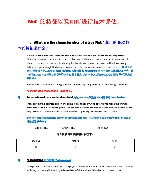
真正的地址(address)及数据(data)封包传输是不会被地址及数据的大小所限制.
Sonics: YES
Arteris: NO 是否提供封包传输技术:
ARM: NO
SONICS 有
Arteris 无
ARM 无
3)
High-frequency switching operation 高频传输运作
Today’s complex SoC’s usually have a large number of clock domains and power domains to allow dynamic voltage and frequency scaling (DVFS) techniques to be applied. Crossing clock (asynchronous) boundaries and power (isolation, voltage level-shifters) boundaries efficiently is a major task as the number of domains increases. Support from the ground-up for many domains is essential for efficient domain spanning and fine-grained power management
电子工程英文缩写词
电子工程英文缩写词解释AAD (adaptive arithmetic decoder):自适应算术译码器AAL(ATM Adaptation Layer):异步转移模式适配层AC(Alternating Current):交流AN(Access Network):接入网ACI(Adjacent Channel Interference):邻频干扰AC(Additional Channel):增补频道A/D(Analog to Digital):模拟信号变换为数字信号ACT(Adjacent Channel Transmission):邻频道传输ADSL(Asymmetrical Digital Subscriber Line):不对称数字用户线路AES(Automatic Electronic Shutter)自动电子快门AGC(Automatic Gain Control):自动增益控制AIC(Auxiliary Information Channel):辅助信息信道ALC(Automatic Level Control):自动电平控制AM(Amplitude Modulation):幅度调制(调幅)AML(Amplitude Modulated Microwave Link):调幅微波链路ARP(Address Resolution Protocol):地址识别协议ASC(Automatic Slope Control):自动斜率控制ASF(Advanced Streaming Format):高级流格式ASK(Amplitude Shift Keying ):幅移键控ATF( Automatic Track Finding):自动磁迹搜索ATM(Asynchronous Transfer Mode):异步传输模式(协议)ATSC(Advanced Television System Committee)先进电视制式委员会BAL(Bit Allocation):比特分配BB(Basis Band):基带BBER(Background Block Error Rate):背景块误码率BC(Broadcast Channel):广播信道BCN(Broadcast Communication Network):广播通信网BDC(Block Down Converter):下变频器BER(Bit Error Rate):误码率B-ISDN(Broadband-Integrated Services Digital Network):宽带综合业务数字网络BS(Bit Stream):比特流(码流)BNC(Bayonet Nut Connector):插入式螺帽连接器BNC(Baby-naked Connector):小型无保护连接器BPF(Band Pass Filter):带通滤波器BPS(Bits Per Second):比特/秒,也写作b/s BRI(Basic Rate Interface):基本速率接口Broad Band Communication:宽带通信BRR:(Bit Rate Reduction):比特率压缩C/CSO(Carrier to Composite Second Order beat ratio):载波复合二次差拍比C/CTB(Carrier to Composite Triple Beat ratio):载波复合三次差拍比C/I(Carrier to Inter-modulation ratio):载波互调比C/N(Carrier to Noise ratio):载噪比CA(Conditional Access):有条件存取(有条件接收)CR(Cable Router):线缆路由器CAC(Conditional Access Control):条件存储控制CAID(Conditional Access Identifier):有条件存取(接收)标志CAP:(Carrierless Amplitude /Phase)无载波调幅调相CATV(Cable Television):有线电视CATV(Community Antenna Television):共用天线电视CC(Channel Coding):通道编码CCIR(International Radio Consultative Committee):国际无线电咨询委员会CCITT(Consultative Committee of International Telephone and Telegraph):国际电报电话咨询委员会CD( Compact Disk ):光盘DSD( Direct Stream Digital):数字直流技术CCU(Communication Control Unit):通信监测单元CDMA(Code Division Multiple Access):码分多址CIF(Common Interleaved Frame):公共交织帧CII(China Information Infrastructure):中国信息基础设施(计划)CS(Circuit Switching):电路交换CLI(CATV Leakage and Ingress):有线电视泄漏与窜入CM(Cable Modem):电缆调制解调器又名线缆调制解调器CM(Cross Modulation):交扰调制CMCI(Cable Modem to CPE Interface):电缆调制解调器至用户屋内设备接口CMTRI(Cable Modem Telephone Return Interface):电缆调制解调器中回传电话接口CMTS(Cable Modem Termination System):电缆调制解调器(Cable Modem)端接系统CC(Coaxial Cable):同轴电缆COFDM(Coded Orthogonal Frequency Division Multiplexing):编码正交频分复用CR(Community Reception):集体接收CPE(Customer Premises Equipment):用户屋内设备CS(Communication Satellite):通信卫星CSMA/CD(Carrier Sense Multiple Access/Collision Detection):公共载波复用通路/冲突检测(用于以太网),也叫带碰撞检测的载波侦听多址、载波侦听多重接入/碰撞检测CSO(Composite Second Order Beat):复合二次差拍CTB(Composite Triple Beat):复合三次差拍CW(Control Word):控制字D/A(Digital to Analog):数字信号变为模拟信号DAC(Digital Analog):数字信号变换为模拟信号的电路DAVIC(Digital Audio Video Council):数字音视频理事会DB(Data Broadcasting):数据广播DBS(Direct Broadcast Satellite):直播卫星DC(Direct Current):直流DCF(Dispersion Compensation Fiber):色散补偿光纤,也叫色散位移光纤DC-SMF(Dispersion Compensation Single Mode Fiber):色散补偿单模光纤DCT(Discrete Cosine Transform):离散余弦变换DFB(Distributed Feedback):分布反馈(激光器)DFB-LD(Distributed Feedback-LD):分布反馈型-激光二极管DFT(Discrete Fourier Transformation):离散傅里叶变换DHCP(Dynamic Host Configuration Protocol):动态主机配置协议DIB(Digital Integrated Broadcasting):数字综合广播DIBEG(Digital Broadcasting Experts Group)数字广播专家组DP(Distribution Point):分配点DLL(Data Link Layer):数据链路层DLS(Dynamic Label Segment):动态标记段DMB(Digital Multimedia Broadcasting)数字多媒体广播DMD(Digital Micromirror Device):数字微波设备DNS(Domain Name System):域名解析系统DOCSIS(Data Over Cable Service Interface Specification):有线电视网络上的数据接口规格DQDB(Distributed Queue Double Bus):分布队列双总线DRC(Dynamic Range Control):动态范围控制DS(Dynamic Scattering):动态散射DSCT(Data Service Component Type):数据业务成分类型DSD (Direct stream Digital):数字直流技术DSF(Dispersion Shift Fiber):色散位移光纤DSL(Digital Subscriber Line):数字用户线路DSM(Digital Storage Media):数字的存储或传输器件DSP(Digital Signal Processor):数字信号处理器DSV(Digital Sum Variation):是一种为了减少数字编码的低频分量的处理方法磁记录或重放系统是不能重放直流或低频成分的,而为了使它能记录含有低频成分的数字编码,将码"1"改为+1,将码"0"改为-1,并在某一时间内求它们的累积值。
数据通信与网络技术词汇大全
数据通信与网络技术词汇大全数据通信与网络技术词汇大全数据通信是通信技术和计算机技术相结合而产生的一种新的通信方式。
接下来我为大家整理了数据通信与网络技术词汇大全,希望对你有帮助哦!数据通信与网络技术词汇大全一:ANAccessNode访问节点HOBHeadofBus总线头HPNAHomePhonelineNetworkingAlliance家庭线网络联盟HRCHybridRingControl混合环控制HSSIHigh-SpeedSerialInterface高速串行接口2B1Q2Binary,1Quaternary两个二进位的,一个四进位的AALATMAdaptationLayerATM适应层ADSLAsymmetricDigitalSubscriberLine非对称数字用户线路CDVCellDelayVariation信元延迟变更CLRCellLossRatio信元丢失比率IDLCIntegratedDigitalLoopCarrier综合数字环路载波AD-PCMAdaptiveDifferentialPulseCodeModulation适应微分-脉冲码调制AMAmplitudeModulation幅度调制AMIAlternateMarkInversion交替标记倒置ANSIAmericanNationalStandardsInstitute美国国家标准协会APSAutomaticProtectionSwitching自动保护开关ARQAutomaticRepeatreQuest自动重复请求ATTAmericanTelephoneTelegraph美国/电报ATMAsynchronousTransferMode异步传输形式ATUADSLTerminationUnitADSL终端单元AWGAmericanWireGauge美国线规BECNBackwardExplicitCongestionNotification反向显示拥塞通知BERBit-ErrorRate位误码率BHBusyHour高峰时BISDNBroadbandIntegratedServicesDigitalNetwork宽带综合业务数字网BOMBeginningOfMessage报头BRIBasicRateInterface基速接口CACConnectionAdmissionControl连接容许控制CADComputer-aidedDesign计算机辅助设计CAEComputer-aidedEngineering计算机辅助工程CAMComputer-aidedManufacturing计算机辅助制造CAPCarrierlessAmplitudeModulation无载波幅度调制CATVCableTelevisionorCommunityAntennaTelevision有线电视或公用天线电视CBDSConstantBitRateDataService不变比特率数据服务CBRContinuousBitRate,orConstantBitRate连续的比特率或不变的比特率CCITTConsultativeCommitteeonInternationalTelegrapha ndTelephone国际和电报咨询委员会CFMConfigurationManagement配置管理CIRCommittedInformationRateCLECCompetitiveLocalExchangeCarrier竞争的本地交换载波CLLMConsolidatedLink-LayerManagement统一链路层管理CLPCellLossPriority单元丢失优先权CMTConnectionManagement连接管理COCentralOffice中心局COICommunityofInterest公共的影响(利益)COMContinuationofMessage报文附加COMSATCommunicationsSatelliteCorporation通信卫星公司数据通信与网络技术词汇大全二:CPECustomerPremiseEquipment客户前提设备CPNCustomerPremisesNode客户前提节点CRCCyclicRedundancyCheck循环冗余校验CSconvergenceSublayer收敛子层CSUChannelServiceUnit信道服务单元DASDualAttachmentStations双附加配置工作站DBSDirectBroadcastSatellite直播卫星DCCDataCommunicationsChannels数据通信信道DCEDataCommunicationsEquipment数据通信设备DEDiscardEligibility丢弃合格DLCDigitalLoopCarrier数字环路载波DLCIData-LinkConnectionIdentifier数据链路连接鉴定DMTDiscreteMultitone离散的多频声DOJDepartmentOfJustice司法部DSLAMDSLAccessMultiplexerDSL访问多路复用器DSPDigitalSignalProcessor数字信令处理器DSUDataServiceUnit数据服务单元DTEDataTerminalEquipment数据终端设备DTPDataTransportProtocol数据传输协议DTPMDataTransportProtocolMachine数据传输协议器EAExtendedAddress扩展地址ECMCoordinationManagement调和管理ECNExplicitCongestionNotification显示拥塞通告ECSAExchangeCarriersStandardsAssociation交换信号标准协会EOEndOffice分局EOMEndofMessage报尾ETSIEuropeanTelecommunicationsStandardsInstitute欧洲电讯标准协会FCCFederalCommunicationsCommission联邦通信委员会FCSFrameCheckSequence帧校验序列FDMFrequencyDivisionMultiplexing频分复用FECForwardErrorControl转发误码控制FECNForwardExplicitCongestionNotification转发显示拥塞通告FEPFront-endProcessor前端处理机FMFrequencyModulation频率调制(调频)FRFrameRelay帧中继FRIFrameRelayInterface帧中继接口FSKFrequencyShiftKeying移频键控(调制),频移键控(法)FSNFullServiceNetwork全服务网络FTAMFileTransferAccessandManagement文件传输访问和管理FTTCFibertotheCurb光纤到路边FTTNFibertotheNode光纤到节点FTTHFibertotheHome光纤到家GANGlobalAreaNetwork全局网GEOSGeo-SynchronousSatellites地球同步卫星GFCGenericFlowControl一般溢出控制HDLCHign-LevelDataLinkControl高级数据链路控制HDSLHigh-SpeedDigitalSubscriberLine高速数字用户线路HDTHostDigitalTerminal主机数字终端HDTVHigh-DefinitionTelevision高明晰度电视HEHeaderExtension报头扩展HECheaderErrorControl报头误码控制HFCHybridFiber/Coax混合光纤/同轴HIPPIHigh-PerformanceParallelInterface高性能并行接口HTU-CHDSLTerminationUnit-CentralHDSL终端单元-局端HTU-RHDSLTerminationUnit-RemoteHDSL终端单元-客户端数据通信与网络技术词汇大全数据通信是通信技术和计算机技术相结合而产生的一种新的通信方式。
移动通信英文缩写与中文对照

3G-MSC 3rd Generation Mobile Switching Centre 第三代移动交换中心3G-SGSN 3rd Generation Serving GPRS Support Node 第三代服务GPRS 的节点3GPP 3rd Generation partnership project 3 代合作项目AAL2 ATM Adaptation Layer type 2 ATM 适配层2AAL5 ATM Adaptation Layer type 5 ATM 适配层5ACIR Adjacent Channel Interference Ratio 邻道干扰比ACLR Adjacent Channel Leakage power Ratio 邻道泄漏功率比ACS Adjacent Channel Selectivity 邻道选择性210ALCAP Access Link Control Application Part 接入链路控制应用部分AMC Adapt Modulation Coding 自适应调制编码ARQ Automatic Repeat Request 自动重复请求ASN.1 Abstract Syntax Notation One 抽象语义描述1ATM Asynchronous Transfer Mode 异步传输模式AuC Authentication Centre 鉴权中心BCH Broadcast Channel 广播信道BCCH Broadcast Control Channel 广播控制信道BER Bit Error Rate 误比特率BGCF Breakout Gateway Control Function 突破网关控制功能BSC Base Station Controller 基站控制器BSS Base Station Subsystem 基站子系统BTS Base Transceiver Station 基站收发机CC Call Control 呼叫控制CCCH Common Control Channel 公共控制信道CCH Control Channel 控制信道CCPCH ` Common Control Physical Channel 公共控制物理信道CDMA Code Division Multiple Access 码分多址CDMA TDD CDMA Time Division Duplex 码分多址时分双工CFN Connection Frame Number 连接帧号CM Connection Management 连接管理CN Core Network 核心网CQI Channel Quality Indicator 信道质量指示CRC Cyclic Redundancy Check 循环冗余检验CRNC Controlling Radio Network Controller 控制的无线网络控制器CS Circuit Switched 电路交换CSCF Call Server Control Function 呼叫服务器控制功能DCA Dynamic channel allocation 动态信道分配DCCH Dedicated Control Channel 专用控制信道DCH Dedicated Transport Channel 专用传输信道DL Downlink 下行链路DOA Direction Of Arrival 到达方向DPCH Dedicated Physical Channel 专用物理信道DRNC Drift Radio Network Controller 漂移无线网络控制器DRNS Drift RNS 漂移RNSDS CDMA Direct Spreading CDMA 直接扩频码分多址DSCH Down-link Shared Channel 下行共享信道DTCH Down-link Traffic Channel 下行业务信道DwPCH Downlink Pilot Channel 下行导频信道DwPTS Downlink Pilot Time Slot 下行导频时隙EIR Equipment Identity Register 设备标识寄存器EP Elementary Procedure 基本过程FACH Forward Access Channel 前向接入信道211FDD Frequency Division Duplex 频分双工FFS For Further Study 进一步研究FP Frame Protocol 帧协议FPACH Fast Physical Access Channel 快速物理接入信道FT Frame Type 帧类型GGSN Gateway GPRS Support Node GPRS 网关支持节点GMM GPRS Mobility Management GPRS 移动性管理GMSC Gateway MSC 网关移动业务中心GPRS General Packet Radio Service 通用分组无线业务GPS Global Positioning System 全球定位系统GRR GPRS Radio Resources GPRS 无线资源GSM Global System for Mobile Communication 全球移动通信系统GTP GPRS Tunneling Protocol GPRS 隧道协议HARQ Hybrid Automatic Repeat Request 混合自动重复请求HFN Hyper Frame Number 超帧号HLR Home Location Register 归属位置寄存器HSDPA High Speed Downlink Packet Access 高速下行分组接入HSS Home Subscriber Server 归属用户服务器IMSI International Mobile Subscriber Identity 国际移动用户标识码IMT-2000 International Mobile Telecommunications 2000国际电联命名3 代移动通信系统IP Internet Protocol 因特网协议IS-2000 IS-95 Evolution Standard (cdma2000) cdma2000ITU International Telecommunication Union 国际电联L1 Layer 1 层1L2 Layer 2 层2LAN Local Area Network 本地网络LMU Location Measurement Unit 位置测量单元MAC Medium Access Control 媒质接入控制MAP Mobile Application Part 移动应用部分MC CDMA Multiple Carrier CDMA 多载波码分多址MC TDMA Multiple Carrier TDMA 多载波时分多址ME Mobile Equipment 移动设备MGCF Media Gateway Control Function 媒体网关控制功能MGW Media Gateway 媒体网关MIB Master Information Block 控制信息块Mcps Mega Chip Per Second 每秒兆ChipMM Mobility Management 移动性管理MPLS MultiProtocol Label Switching 多协议标签交换MRF Media Resource Function 媒体资源功能MRFC Media Resource Function Controller 媒体资源功能控制器MRFP Media Resource Function Processor 媒体资源功能处理器MSC Mobile Services Centre 移动业务中心212MTP Message Transfer Part 消息传输部分MTP3-B Message Transfer Part level 3 3 级消息传输部分M3UA MTP3 User Adaptation Layer MTP3 用户适配层NAS Non Access Stratum 非接入层NBAP NodeB Application Part Node B 应用部分O&M Operation and Maintenance 操作维护PC Power Control 功率控制PCCH Paging Control Channel 寻呼控制信道PCCPCH Primary Common Control Physical Channel 基本公共控制物理信道PCH Paging Channel 寻呼信道PDSCH Physical Downlink Shared Channel 物理下行链路共享信道PLMN Public Land Mobile Network 公共陆地移动网PPP Point-to-Point Protocol 点对点协议PRACH Physical Random Access Channel 物理随机接入信道PS Packet Switched 分组交换PSTN Public Swithed Telephone Network 公共电话交换网络PUSCH Physical Uplink Shared Channel 物理上行链路共享信道QAM Quadrature Amplitude Modulation 正交幅度调制QE Quality Estimate 质量评估QPSK QuadriPhase Shift Keying 四相移键控QoS Quality of Service 业务质量R-SGW Roaming Signalling Gateway 漫游信令网关RAB Radio access bearer 无线接入承载RACH Random Access Channel 随即接入信道RANAP Radio Access Network Application Part 无线接入网应用部分RAT Radio Access Technology 无线接入技术RL Radio Link 无线链路RLC Radio Link Control 无线链路控制RNC Radio Network Controller 无线网络控制器RNS Radio Network Subsystem 无线网络子系统RNSAP Radio Network Subsystem Application Part 无线网络子系统应用部分RNTI Radio Network Temporary Identity 无线网络临时识别RR Radio Resources 无线资源RRC Radio Resource Control 无线资源控制RSVP Resource ReserVation Protocol 资源保留协议RTCP Real Time Control Protocol 实时控制协议RTP Real Time Protocol 实时协议SA Service Area 服务区域SABP service area broadcast protocol 服务区广播协议SAP Service Access Point 服务接入点SBM Subnetwork Bandwidth Management 子网带宽管理SC TDMA Single Carrier TDMA 单载波时分多址SSCF Service Specific Co-ordination Function 特定业务协调功能213SCCP Signalling Connection Control Part 信令连接控制部分SCH Synchronization Channel 同步信道SCCPCH Secondary Common Control Physical Channel 辅助公共控制物理信道SCP Service Control Point 业务控制点SCTP Simple Control Transmission Protocol 简单控制传输协议SFN System Frame Number 系统帧号SGSN Serving GPRS Support Node GPRS 服务支持节点SIB System Information Block 系统信息块SIM Subscriber Identity Module 用户识别模块SLF Subscrīption Location Function 签约位置功能SM Session Management 会话管理SRNC Serving Radio Network Controller 服务无线网络控制SRNS Serving RNS 服务RNSSS7 Signalling System No. 7 7 号信令系统SSCF Service Specific Co-ordination Function 具体业务协调功能SSCF-NNI Service Specific Coordination Function – Network Node Interface 具体业务协调功能网元接口SSCOP Service Specific Connection Oriented Protocol 特定业务面向连接协议.STM Synchronous Transfer Mode 同步传输模式.T-SGW Transport Signalling Gateway 传输信令网关TB Transport Block 传输块TBS Transport Block Set 传输块集TCP Transfer Control Protocol 传输控制协议TDD Time Division Duplex 时分双工TDMA Time Division Multiple Access 时分多址接入TD-SCDMA Time Division Synchronous CDMA 时分同步--码分多址接入TFC Transport Format Combination 传送格式组合TFCI Transport Format Combination Indicator 传送格式组合指示TFCS Transport Format Combination Set 传送格式组合集TFI Transport Format Indicator 传送格式指示TFS Transport Format Set 传送格式集ToA Time of arrival 到达时间TPC Transmit Power Control 发射功率控制TSN Transmission Sequence Number 传输序列号TTI Transmission Time Interval 传输时间间隔UDP User Datagram Protocol 用户数据报协议UE User Equipment 用户设备UL Uplink 上行链路UMTS Universal Mobile Telecommunication System 陆地移动通信系统UpPTS Uplink Pilot Time slot 上行导频时隙UpPCH Uplink Pilot Channel 上行导频信道USCH Up-link Shared Channel 上行共享信道USIM UMTS Subscriber Identity Module UMTS 用户识别模块214UTRAN UMTS Terrestrial Radio Access Network UMTS 陆地无线接入网VC Virtual Circuit 虚电路VLR Visitor Location Register 访问位置寄存器WAP Wireless Application Protocol 无线应用协议WCDMA Wideband Code Division Multiple Access 宽带cdmaWG Working Group 工作组WWW World Wide Web 万维网XRES EXpected user RESponse 期待的用户响应1X EV 1X Evolution 1X增强1X EV-DO 1X Evolution Data Only 1X增强-数据1X EV-DV 1X Evolution Data & Voice 1X增强-数据与语音1xEV-DO 1x evolution Data Optimized 1x演进数据优化24PB 24V Power Board 24V电源板2G BTS 2G Base Station Transceiver 仅支持IS-95空中接口标准的BTS3G BTS 3G Base Station Transceiver 支持IS-2000空中接口标准的BTSAAAA Authentication Authorization Accounting 认证、授权、记帐AAL ATM Adaptation Layer ATM适配层AAL2 ATM Adaptation Layer type 2 ATM 适配层2AAL5 ATM Adaptation Layer type 5 ATM适配层5Abis Interface Abis Interface—the interface of BSC--BTS 基站控制器和基站收发信机间接口ABS Air Break Switch 空气开关AC Asynchronous Capsule 异步包ACB Amplifier Control Board 放大器控制板ACCH Associated Control Channel 随路控制信道ACCM Asynchronous Control Character Map 异步控制字符映射ACIR Adjacent Channel Interference Ratio 相邻信道干扰比ACK Acknowledgement 应答ACLR Adjacent Channel Leakage Power Ratio 相邻信道泄漏功率比ACS Adjacent Channel Selectivity 相邻信道选择性ADF Application Dedicated File 应用专用文件ADN Abbreviated Dialing Numbers 按字母顺序排列的电话号码薄AESA ATM End System Address ATM末端系统地址AGC Automatic Gain Control 自动增益控制AH Authentication Header 鉴权报头 AI Acquisition Indicator 捕获指示AICH Acquisition Indicator Channel 捕获指示信道AID Application IDentifier 应用标识符AIUR Air Interface User Rate 空中接口用户速率AK Anonymity key 匿名密钥ALC Automatic Level Control 自动电平控制ALCAP Access Link Control Application Protocol 接入链路控制应用协议 ALW Always 一直AM Acknowledged Mode 应答模式AMB Attenuation Matching Board 衰减匹配板AMF Authentication Management Field 鉴权管理域AMP Address Management Protocol 地址管理协议AMR Adaptive Multi Rate 可采纳的多速率AN Access network 接入网络ANID Access Network Identifiers 接入网标识AP Access preamble 接入前缀APB ATM Process Board ATM接入处理板APD AC Power Distribution Module 交流配电模块APDU Application Protocol Data Unit 应用协议数据单元API Application Programming Interface 应用程序接口ARM ARM processor ARM处理器ARP Address Resolution Protocol 地址解析协议ARQ Automatic Repeat Request 自动重发请求AS Access Stratum 接入层ASC Access Service Class 接入业务级A-SGW Access Signaling Gateway 接入信令网关ASN.1 Abstract Syntax Notation One 抽象语法表示1AT Access terminal 接入终端ATM Asynchronous Transfer Mode 异步传输模式ATR Answer To Reset 复位回答ATT Attenuator 衰减器AUC Authentication Center 鉴权中心AUTN Authentication token 鉴权标记AWGN Additive White Gaussian Noise 加性高斯白噪声A Interface A Interface—the interface of BSC-MSC 移动交换中心与基站子系统间接口BB-BDS Backplane of Baseband Digital Subsystem 基带数字子系统背板 BBDS Backplane of BDS BDS框的背板BBS BTS Baseband Subsystem 基站基带子系统BCC Bear Channel Connect 承载通路连接BCCH Broadcast Control Channel 广播控制信道BCFE Broadcast Control Functional Entity 广播控制功能实体BCH Broadcast Channel 广播信道BCS BTS Communication Subsystem 基站通信子系统BCSN Backplane of Circuit Switch Network 电路交换网背板BCTC Backplane of Control Center 控制中心背板BDM Baseband Digital Module 基带数字模块BDM1900 1.9G Baseband Digital Module 微基站1.9G基带数字模块BDM800 800M Baseband Digital Module 微基站800M基带数字模块 BDS Baseband Digital System 基带数字系统BER Bit Error Ratio 误码率,比特差错率BGPS Backplane of GPS GPS背板BGT Block Guard Time 块守护时间BIC Baseline Implementation CapabilitiesBID Binding Identity 捆绑标识BIM BDS Interface Module BDS系统接口模块B-ISDN ISDN Broadband ISDN 宽带BLER Block Error Rate 误块率BLPA Backplane of LPA LPA框的背板BMC Broadcast/Multicast Control 广播/多址控制BOC Bell Operating Company 贝尔运行公司BPD BDS Power Distribute BDS机柜电源分配模块BPSK Binary Phase Shift Keying 二进制移相键控BPSN Backplane of Packet Switch Network 分组交换网背板BPWS Backplane of PWS PWS框的背板BRFE Backplane of RFE RFE框的背板BRFS Backplane of TRX and BDM/RFM BDM/RFM和TRX的连接背板BS Base Station 基站BSC Base Station Controller 基站控制器BSM Base Station Management 基站管理系统BSP Board Support Package 板支持包BSS Base Station System 基站系统BSSAP Base Station Subsystem Application Part 基站子系统应用部分BTM BTS Test Module BTS告警模块BTRX Backplane of TRX TRX框的背板BTS Base Transceiver System 基站收发信机BUSN Backplane of Universal Switching Network 通用业务网背板BWT Block Waiting Time 块等待时间CCA Certificate Authentication 证书认证CAA Capacity Allocation Acknowledgement 空量分配应答CAMEL Customized Application for Mobile network Enhanced Logic 用于移动网络增强逻辑定制的应用CAP CAMEL Application Part CAMEL应用部分C-APDU Command APDU 命令APDUCB Cell Broadcast 小区广播CBA IPI CMM-Based Appraisals for Internal Process Improvement 用于内部过程改进的基于CMM的评价CBR Constant Bit Rate 固定比特率CBS Cell Broadcast Service 小区广播业务CC Control Channel 控制信道CC/PP Composite Capability/Preference Profiles 合成能力/优先档案CCB Configuration Control Board 配置控制委员会CCBS Completion of Calls to Busy Subscriber 呼叫忙用户的完成CCCH Common Control Channel 公共控制信道CCF Call Control Function 呼叫控制功能CCH Control Channel 控制信道CCK Corporate Control Key 合并控制键CCM Communication Control Module 通信控制模块CCP Compression Control Protocol 压缩控制协议CCPCH Common Control Physical Channel 公共控制物理信道CCTrCH Coded Composite Transport Channel 编码合成传送信道CD Capacity Deallocation/Collision Detection 空量解除分配/冲突检测 CDA Capacity Deallocation Acknowledgement 容量解除分配的应答CDF Command Dispatch Functions 命令分发功能CDMA Code Division Multiple Access 码分多址CDR Call Detail Record 呼叫细节记录CDSU Channel/Data Service Unit 信道/数据服务单元CE Channel Element 信道单元CEB Channel Element Board 信道单元板CES Channel Element Subsystem 信道单元子系统CFN Connection Frame Number 连接帧号CGI Common Gateway Interface 公共网关接口CHAP Challenge Handshake Authentication Protocol 质询握手认证协议 CHM Channel Processing Module 信道处理模块CHM-1X Channel Processing Module for cdma2000 信道处理模块,采用CSM5000芯片,支持IS-2000空中接口标准CHM-95 Channel Processing Module for IS-95 信道处理模块,采用CSM1.5芯片,支持IS-95空中接口标准CHUB Control HUB 控制流集线器CIB Circuit-bearer Interface Board 电路承载通道接口板CIC Circle Identify Code 地面电路识别号CLA Class 级CLK Clock 时钟CLKD CLOCK Distributor 时钟分发驱动板CLKG CLOCKGenerator 时钟产生CLNP Connectionless network protocol 无连接网络协议CLNS Connectionless network service 无连接网络业务CM Configuration Management 配置管理CMB Combiner 合路器CMF Connection Monitor Function 连接监控功能CMIP Common Management Information Protocol 公共管理信息协议 CMIS Common Management Information Service 公共管理信息服务CMM Capability Maturity Model 能力成熟度模型CMU Carnegie-Mellon University 卡耐基&8226;梅隆大学CN Core Network 核心网CNAP Calling Name Presentation 主叫号码显示CNL Co-operative Network List 合作操作网络表COA Care-of-Address 转交地址COCOMO Constructive Cost Model 构造性成本模型CONS Connection-oriented network service 面向连接的网络业务CPCH Common Packet Channel 公共分组信道CPCS Common Part Convergence Sublayer 公共聚合子层部分CPICH Common Pilot Channel 公共导频信道CPM Calling Processing Module 呼叫处理模块CPP Core Processor Part 核心处理部分CPS Common Part Sublayer 公共子层部分 CPU Central Processing Unit 中心处理单元CR Change Request 变更请求CRC Cyclic Redundancy Check 循环冗余校验CRF Command Resolve Function 命令解析功能CRNC Controlling Radio Network Controller 主控无线器C-RNTI Cell Radio Network Temporary Identity 小区无线网络临时识别符CS Circuit Switched 电路交换CSCF Call Server Control Function 呼叫服务器控制功能CSE Camel Service Environment Camel 业务环境CS-GW Circuit Switched Gateway 电路交换网关CSM Cell Site Modem 基站调制解调器CSM5000 Cell Site Modem ASIC 5000 基站调制解调器专用芯片CSU/DSU Channel Service Unit/ Digital Service Unit 信道数据服务单元 CTCH Common Traffic Channel 公共业务信道CTDMA Code Time Division Multiple Access 码时分多址C-TPDU Command TPDU 命令TPDUCW Continuous Wave (unmodulated signal) 连续波(未调制信号)DD_K DBS Kernel Module 数据库核心模块D_M D_Method 数据库关系表方法模块D_S D_Service 数据库维护模块D_V D_View 数据库存取接口模块DAC Digital-to-Analog Converter 数-模转换器DAD Destination Adress 目的地址DAM DECT Authentication Module DECT鉴权模型DBS Database Subsystem 数据库子系统DC Dedicated Control (SAP) 专用控制(SAP)DCA Dynamic Channel Allocation 动态的信道分配DCCH Dedicated Control Channel 专用控制信道DCH Dedicated Channel 专用信道DDI Direct Dial In 直接拨号进DECT Digital Enhanced Cordless Telecommunications 数字增强无绳电信 DF Dedicated File 专用文件DHCP Dynamic Host Configuration Protocol 动态的宿主配置协议DHO Diversity Handover 分集切换DIF Data Intermediate Frequency Module 数字中频模块diff-serv Differentiated services 特殊的业务DIU Digital Interface Module 数字(中频)接口模块DL Downlink (Forward Link) 下行链路(前向链路)DLC Data Link Control 数据链路层控制DN Destination Network 目的网络DNS Directory Name Service 目录名称业务DO Data Object 数据对象DoD Department of Defense 美国国防部DOI Domain of Interpretation 解析域DP Defect Prevention 缺陷预防DPC Destination Point Code 目的地信令点编码DPCCH Dedicated Physical Control Channel 专用物理控制信道DPCH Dedicated Physical Channel 专用物理信道DPDCH Dedicated Physical Data Channel 专用物理数据信道DRAC Dynamic Resource Allocation Control 动态的资源分配控制DRC Data Rate Control 数据速率控制DRNC Drift Radio Network Controller 变动的无线网络控制器DRNS Drift RNS 变动的RNSDRX Discontinuous Reception 非连续接收DSA Digital Signature Algorithm 数字签名算法DS-CDMA Direct-Sequence Code Division Multiple Access 直扩-码分多址DSCH Downlink Shared Channel 下行共享信道DSM Data Service Module 数据服务模块DTB Digital Trunk Board 数字中继板DTCH Dedicated Traffic Channel 专用业务信道DTI Digital Trunk Interface Element 数字中继接口单元DTMF Dual Tone Multiple Frequency 多音频拨号音DTX Discontinuous Transmission 非连续传输DUP Duplexer 双工器EECTRA European Committee of Telecommunications Regulatory Affairs 欧洲电信常规事务委员会EDC Error Detection Code byte 检错码字节EDGE Enhanced Data rates for GSM Evolution GSM改进型的增强数据速率EF Elementary File 基本文件EFD Event Forwarding Discriminator 事件前转辨别器E-GGSN Enhanced GGSN 增强的GGSNEGPRS Enhanced GPRS 增强的GPRSEHB (Ethernet HUB Board)以太网共享式HUB板E-HLR Enhanced HLR 增强的HLREIRP Equivalent Isotropic Radiated Power 等效各向内性辐射功率EJB Enterprise Java Beans 企业Java组件模型EMC Electromagnetic Compatibility 电磁兼容性EMF Network Element Mediation Function 网元中介功能EMI Electromagnetic interference 电磁干扰EMS electromagnetic susceptibility 电磁敏感性ESB Ethernet Switch Board 以太网交换板ESD electrostatic discharge 静电放电ESP Encapsulating Security Payload 封装安全载荷ESU Extended subscriber unit 扩展用户单元ETSI European Telecommunications Standards Institute 欧洲电信标准研究院etu elementary time unit 基本时间单元EUT equipment under test 被试设备FF/R-CCCH Forward / Reverse Common Control Channel 前反向公共控制信道F/R-DSCH Forward/Reverse Dedicated Signal Channel 前反向专用信令信道F/R-DCCH Forward / Reverse Dedicated Control Channel 前反向专用控制信道F/R-FCH Forward / Reverse Fundamental Channel 前反向基本信道F/R-PICH Forward / Reverse Pilot Channel 前反向导频信道F/R-SCCH Forward / Reverse Supplemental Code Channel 前反向补充码信道F/R-SCH Forward / Reverse Supplemental Channel 前反向补充信道FA Foreign Agent 外地代理FAC Foreign Agent Challenge 外地代理质询FACH Forward Access Channel 前向业务信道F-APICH Dedicated Auxiliary Pilot Channel 前向专用辅助导频信道F-ATDPICH Auxiliary Transmit Diversity Pilot Channel 辅助发射分级导频信道FAUSCH Fast Uplink Signaling Channel 快速上行链路信令信道FAX Facsimile 传真F-BCCH Broadcast Control Channel 前向广播控制信道FBI Feedback Information 反馈信息F-CACH Common Assignment Channel 前向公共指配信道FCI File Control Information 文件控制信息FCP Flow Control Protocol 流量控制协议F-CPCCH Common Power Control Channel 前向公共功率控制信道FCS Frame Check Sequence 帧校验序列FD Full duplex 全双工FDD Frequency Division Duplex 频分双工FDMA Frequency Division Multiple Access 频分多址FE Front End 射频收发前端FEC Forward Error Correction 前向纠错FER Frame Erasure Rate/Frame Error Rate 误帧率FFS For Further Study 为进一步研究Flexible-Rate Flexible Data Rate 灵活的数据速率FLPC Forward Link Power Control 前向链路功率控制FM Fault Management 故障管理FN Frame Number 帧号FNUR Fixed Network User Rate 固定的网络用户速率FP Function Point 功能点F-PCH Paging Channel 前向寻呼信道F-QPCH Quick Paging Channel 前向快速寻呼信道FS Frequency Synthesizer 频率合成器FSB Frequency Synthesizer Board 频率合成板F-SYNCH Sync Channel 前向同步信道FTAM File Transfer Access Maintenance 文件传输存取维护FTB Fiber Transceiver Board 光纤收发板FTC Forward Traffic Channel 前向业务信道F-TDPICH Transmit Diversity Pilot Channel 前向发射分集导频信道FTP File Transfer Protocol 文件传输协议GGC General Control (SAP) 一般控制(SAP)GCM GPS Control Module GPS控制模块GID1 Group Identifier (level 1) 组识别符(级别1)GID2 Group Identifier (level 2) 组识别符(级别2) GLI GE Line Interface GE线接口GMSC Gateway MSC 网关MSCGMSK Gaussian Minimum Shift Keying 最小高斯移位键控GP Guard Period 保护时间GPCM General Purpose Chip-select Machine 通用片选状态机GPRS General Packet Radio Service 通用分组无线业务GPS GPS Timing Module 定时频率模块GPSR Global Position System Receiver 全球定位系统接收机GPSTM GPS Timing Module GPS定时模块GRE Generic Routing Encapsulation 通用路由封装GSM Globe System for Mobil Communication 全球移动通信系统GSN GPRS Support Nodes GPRS支持的节点GTP GPRS Tunneling Protocol GPRS隧道传输协议HHA Home Agent 归属代理HCS Hierarchical Cell Structure 分层小区结构H-CSCF Home CSCF 归属CSCSHDLC High-level data link control HDLC协议HDR High Data Rate 高速数据速率HE-VASP Home Environment Value Added Service Provider 归属环境的增值业务提供者HF Human Factors 人为因素HHO Hard Handover 硬切换HIRS High-speed Interconnect Router Subsystem 高速互连路由子系统 HLR Home Location Register 归属位置寄存器HN Home Network 归属网络HO Handover 切换HPA High Power Amplifier 高功放HPLMN Home Public Land Mobile Network 归属公共陆地移动网络HPS Handover Path Switching 切换路径交换HRPD High rate packet data 高速率分组数据HRR Handover Resource Reservation 切换资源预留HSCSD High Speed Circuit Switched Data 高束的电路交换数据HSS Home Subscriber Server 归属用户服务器HTTP Hyper Text Transfer Protocol 超文本传输协议HTTPS Hyper Text Transfer Protocol 安全的超文本传输协议HWB HW-signal process Board HW信号处理板II/O Input/Output 输入/输出IANA Internet Assigned Numbering Authority 互联网地址分配机构I-Block Information Block 信息块IC Intergroup Coordination 组间协调ICC Integrated Circuit Card 集成电路卡ICGW Incoming Call Gateway 呼入网关ID Identifier 识别符IDEAL Initiating-Diagnosing-Establishing-Acting-Leveraging 启动、诊断、建立、行动、推行IE Information Element 信息元素IEC International Electrotechnical Commission 国际电气委员会IETF Internet Engineering Task Force 互联网工程任务组IF Intermediate Frequency 中频IFS Information Field Sizes 信息域大小IFSC Information Field Size for the UICC UICC的信息域大小IFSD Information Field Size for the Terminal 终端的信息域大小IIC Integrated Circuit Interface Circuit 集成电路接口电路IKE Internet Key Exchange 互联网密钥交换IM Intermodulation 互调失真IMA Inverse Multiplexing on ATM ATM上的反向复用IMAB IMA Board IMA/ATM协议处理板IMEI International Mobile Equipment Identity 国际移动设备识别IMGI International mobile group identity 国际移动组织识别IMSI International Mobile Subscriber Identity 国际移动用户识别IMT-2000 International Mobile Telecommunications 2000 国际移动电信2000IMUN International Mobile User Number 国际移动用户号IN Intelligent Network 智能网INAP Intelligent Network Application Part 智能网应用部分INF INFormation field 信息域IP Internet Protocol Internet协议IPB IP Process Board IP处理板IPCP IP Control Protocol IP控制协议IP-M IP Multicast IP多址广播IPSec IP Security IP安全协议ISAKMP Internet Security Association and Key Management Protocol 互联网SA和密钥管理协议ISCP Interference Signal Code Power 干扰信号码功率ISDN Integrated Services Digital Network 集成业务数字网ISM Integrated Software Management 集成软件管理ISO International Standardization Organization 国际标准化组织ISP Internet Service Provider Internet业务提供商ISUP ISDN User Part ISDN用户部分ITU International Telecommunications Union 国际电信联盟IUI International USIM Identifier 国际USIM识别符IWFB InterWorking Function Board IWF(用于手机上网的辅助设备)背板 JJ2EE Java 2 Platform Enterprise Edition Java2平台企业板JAR file Java Archive File Java档案文件JD Joint Detection 联合检测JDMK Java Dynamic Management Kit Java动态管理开发包JMS Java Message Service Java消息服务JNDI Java Naming Directory Interface Java命名的目录接口JP Joint Predistortion 联合预失真JPEG Joint Photographic Experts Group 摄影专家联合小组JTAPI Java Telephony Application Programming Interface Java电话的应用程序接口JTS Java Transaction Service Java事务处理服务JVM Java Virtual Machine Java虚拟机Kkbps kilo-bits per second 每秒千比特KP Key Practice 关键实践KPA Key Process Area 关键过程域KSLOC Kilo Source Lines Of Code 千行源代码ksps kilo-symbols per second 每秒千符号LL1 Layer 1 (physical layer) 层1(物理层)L2 Layer 2 (data link layer) 层2(数据链路层)L3 Layer 3 (network layer) 层3(网络层)L3Addr Layer 3 Address 第三层地址LAC Link Access Control 链路接入控制LAI Location Area Identity 位置区域识别LAN Local Area Network 本地网LATA Local Access and Transport Area 本地接入和传送区域LCD Low Constrained Delay 低限制延迟LCF Link Control Function 连接控制功能LCP Link Control Protocol 链路控制协议LCS Location Services 定位业务LE Local Exchange 本地交换机LEN Length 长度LFM Local Fibre Module 近端光模块LLC Logical Link Control 逻辑链路控制LMF 本地管理功能LMT Local Management Terminal 本地维护终端LN Logical Name 逻辑名LNA Low Noise Amplifier 低噪声放大器LOMC Local OMC 本地操作维护中心LOS Line Of Sight 视距LPA Linear Power Amplifier 线性功放LPF Low Pass Filter 低通滤波器LRU Large Replacing Unite 较大可替代单元LSA Localised Service Area 本地化的业务区LSB Least Significant Bit 最低有效比特LTZ Local Time Zone 本地时区LUP Location Update Protocol 位置更新协议MM&C Monitor and Control 监控MA Multiple Access 多址MAC Message authentication code (encryption context) 消息鉴权码(保密)MAF Application Management Features 管理应用功能MAHO Mobile Assisted Handover 移动台协助的切换MAP Mobile Application Part 移动应用部分MC Message Center 短消息中心(SMC)MCC Mobile Country Code 移动国家码MCE Module Control Element 模块控制单元Mcps Mega-chips per second 每秒兆chipsMCU Media Control Unit 媒质控制单元MDIV Diversity 分集接收滤波器MDIV800 Micro Diversity 微基站800M分集接收滤波器 MDN Mobile Directory Number 移动用户号码簿号码MDS Multimedia Distribution Service 多媒体分布业务MDUP Duplex 双工器MDUP800 Micro Duplex 微基站800M双工器ME Mobile Equipment 移动设备MEHO Mobile evaluated handover 移动台估计的切换MER Message Error Rate 误消息率MExE Mobile station (application) Execution Environment 移动台(应用)执行环境MF Mediation Function 中介功能MGCF Media Gateway Control Function 媒质关卡控制功能MGCP Media Gateway Control Part 媒质关卡控制部分MGPS Micro GPS 微基站GPSMGT Mobile Global Title 移动全球称号MGW Media GateWay 媒质关卡MHEG Multimedia and Hypermedia Information Coding Expert Group 多媒体和超媒体信息编码专家组MHz Mega Hertz 兆赫兹MIB Management Information Base 管理信息库MIF Management Information Function 管理信息功能MIN Mobile Identification Number 移动台识别码MIP Mobil IP 移动IPMIPS Million Instructions Per Second 每秒百万次指令MIT MO Instance Tree MO实例树MLNA Micro Low Noise Amplifier 低噪声放大器MLNA800 Micro Low Noise Amplifier 微基站800MLNAMM Mobility Management 移动性管理MMI Man Machine Interface 人机接口MML Man Machine Language 人机语言MNC Mobile Network Code 移动网络码MNIC Multi-service Network Interface Card 多功能接口网板MNP Mobile Number Portability 移动号可携带性MO Mobile Originated 移动台启呼MOF MO administration Function MO管理功能MOHO Mobile Originated Handover 移动台启呼的切换MONB MONIOTR BOARD 监控板MOS Mean Opinion Score 平均意见分MPA Micro Power Amplifier 微基站功放MPA800 Micro Power Amplifier 微基站800M功放MPB Main Process Board 主处理板MPC8260 Motorola Power PC 8260 摩拖罗拉的CPUMPC860 Motorola的高性能的通讯处理器MPD Micro-BTS Power Distribution 微基站电源模块MPEG Moving Pictures Experts Group 移动图像专家组MPM MSC Processing Module MSC处理模块MRB Media Resource Board 媒体资源板MRF Media Resource Function 媒质资源功能MS Mobile Station 移动台MSB Most Significant Bit 最高有效比特MSC Mobile Switching Center 移动交换中心MSE MExE Service Environment MexE业务环境MSG Management Steering Group 管理指导组MSID Mobile Station Identifier 移动台识别符MSIN Mobile Station Identification Number 移动台识别号码MSM Message Switching Module 消息交换模块MSP Multiple Subscriber Profile 多用户档案MSU Main subscriber unit 主用户单元MT Mobile Termination 面向终端的移动MTBF 平均无故障时间间隔MTP Message Transfer Part 消息传递部分MTP3-B Message Transfer Part level 3 消息传递部分级别3MTRX800 Micro Transmitter & Receiver 微基站800M收发信机MTSI Master To Slave Interface 主备用接口MUI Mobile User Identifier 移动用户识别符NNAD Node Address byte 节点地址字节NAI Network Access Identifier 网络接入标识NAS Non-Access Stratum 非接入层NBAPNBAP Node B Application Part Node B应用部分NCK Network Control Key 网络控制键NCM Network Control Module 网络控制模块NDC National Destination Code 国际目的码NDUB Network Determined User Busy 网络用户忙NE Network Element 网元。
移动通信术语英文缩写对照

3G-MSC 3rd Generation Mobile Switching Centre 第三代移动交换中心3G-SGSN 3rd Generation Serving GPRS Support Node 第三代服务GPRS 的节点3GPP 3rd Generation partnership project 3 代合作项目AAL2 ATM Adaptation Layer type 2 ATM 适配层2AAL5 ATM Adaptation Layer type 5 ATM 适配层5ACIR Adjacent Channel Interference Ratio 邻道干扰比ACLR Adjacent Channel Leakage power Ratio 邻道泄漏功率比ACS Adjacent Channel Selectivity 邻道选择性210ALCAP Access Link Control Application Part 接入链路控制应用部分AMC Adapt Modulation Coding 自适应调制编码ARQ Automatic Repeat Request 自动重复请求ASN.1 Abstract Syntax Notation One 抽象语义描述1ATM Asynchronous Transfer Mode 异步传输模式AuC Authentication Centre 鉴权中心BCH Broadcast Channel 广播信道BCCH Broadcast Control Channel 广播控制信道BER Bit Error Rate 误比特率BGCF Breakout Gateway Control Function 突破网关控制功能BSC Base Station Controller 基站控制器BSS Base Station Subsystem 基站子系统BTS Base Transceiver Station 基站收发机CC Call Control 呼叫控制CCCH Common Control Channel 公共控制信道CCH Control Channel 控制信道CCPCH ` Common Control Physical Channel 公共控制物理信道CDMA Code Division Multiple Access 码分多址CDMA TDD CDMA Time Division Duplex 码分多址时分双工CFN Connection Frame Number 连接帧号CM Connection Management 连接管理CN Core Network 核心网CQI Channel Quality Indicator 信道质量指示CRC Cyclic Redundancy Check 循环冗余检验CRNC Controlling Radio Network Controller 控制的无线网络控制器CS Circuit Switched 电路交换CSCF Call Server Control Function 呼叫服务器控制功能DCA Dynamic channel allocation 动态信道分配DCCH Dedicated Control Channel 专用控制信道DCH Dedicated Transport Channel 专用传输信道DL Downlink 下行链路DOA Direction Of Arrival 到达方向DPCH Dedicated Physical Channel 专用物理信道DRNC Drift Radio Network Controller 漂移无线网络控制器DRNS Drift RNS 漂移RNSDS CDMA Direct Spreading CDMA 直接扩频码分多址DSCH Down-link Shared Channel 下行共享信道DTCH Down-link Traffic Channel 下行业务信道DwPCH Downlink Pilot Channel 下行导频信道DwPTS Downlink Pilot Time Slot 下行导频时隙EIR Equipment Identity Register 设备标识寄存器EP Elementary Procedure 基本过程FACH Forward Access Channel 前向接入信道211FDD Frequency Division Duplex 频分双工FFS For Further Study 进一步研究FP Frame Protocol 帧协议FPACH Fast Physical Access Channel 快速物理接入信道FT Frame Type 帧类型GGSN Gateway GPRS Support Node GPRS 网关支持节点GMM GPRS Mobility Management GPRS 移动性管理GMSC Gateway MSC 网关移动业务中心GPRS General Packet Radio Service 通用分组无线业务GPS Global Positioning System 全球定位系统GRR GPRS Radio Resources GPRS 无线资源GSM Global System for Mobile Communication 全球移动通信系统GTP GPRS Tunneling Protocol GPRS 隧道协议HARQ Hybrid Automatic Repeat Request 混合自动重复请求HFN Hyper Frame Number 超帧号HLR Home Location Register 归属位置寄存器HSDPA High Speed Downlink Packet Access 高速下行分组接入HSS Home Subscriber Server 归属用户服务器IMSI International Mobile Subscriber Identity 国际移动用户标识码IMT-2000 International Mobile Telecommunications 2000国际电联命名3 代移动通信系统IP Internet Protocol 因特网协议IS-2000 IS-95 Evolution Standard (cdma2000) cdma2000ITU International Telecommunication Union 国际电联L1 Layer 1 层1L2 Layer 2 层2LAN Local Area Network 本地网络LMU Location Measurement Unit 位置测量单元MAC Medium Access Control 媒质接入控制MAP Mobile Application Part 移动应用部分MC CDMA Multiple Carrier CDMA 多载波码分多址MC TDMA Multiple Carrier TDMA 多载波时分多址ME Mobile Equipment 移动设备MGCF Media Gateway Control Function 媒体网关控制功能MGW Media Gateway 媒体网关MIB Master Information Block 控制信息块Mcps Mega Chip Per Second 每秒兆ChipMM Mobility Management 移动性管理MPLS MultiProtocol Label Switching 多协议标签交换MRF Media Resource Function 媒体资源功能MRFC Media Resource Function Controller 媒体资源功能控制器MRFP Media Resource Function Processor 媒体资源功能处理器MSC Mobile Services Centre 移动业务中心212MTP Message Transfer Part 消息传输部分MTP3-B Message Transfer Part level 3 3 级消息传输部分M3UA MTP3 User Adaptation Layer MTP3 用户适配层NAS Non Access Stratum 非接入层NBAP NodeB Application Part Node B 应用部分O&M Operation and Maintenance 操作维护PC Power Control 功率控制PCCH Paging Control Channel 寻呼控制信道PCCPCH Primary Common Control Physical Channel 基本公共控制物理信道PCH Paging Channel 寻呼信道PDSCH Physical Downlink Shared Channel 物理下行链路共享信道PLMN Public Land Mobile Network 公共陆地移动网PPP Point-to-Point Protocol 点对点协议PRACH Physical Random Access Channel 物理随机接入信道PS Packet Switched 分组交换PSTN Public Swithed Telephone Network 公共电话交换网络PUSCH Physical Uplink Shared Channel 物理上行链路共享信道QAM Quadrature Amplitude Modulation 正交幅度调制QE Quality Estimate 质量评估QPSK QuadriPhase Shift Keying 四相移键控QoS Quality of Service 业务质量R-SGW Roaming Signalling Gateway 漫游信令网关RAB Radio access bearer 无线接入承载RACH Random Access Channel 随即接入信道RANAP Radio Access Network Application Part 无线接入网应用部分RAT Radio Access Technology 无线接入技术RL Radio Link 无线链路RLC Radio Link Control 无线链路控制RNC Radio Network Controller 无线网络控制器RNS Radio Network Subsystem 无线网络子系统RNSAP Radio Network Subsystem Application Part 无线网络子系统应用部分RNTI Radio Network Temporary Identity 无线网络临时识别RR Radio Resources 无线资源RRC Radio Resource Control 无线资源控制RSVP Resource ReserVation Protocol 资源保留协议RTCP Real Time Control Protocol 实时控制协议RTP Real Time Protocol 实时协议SA Service Area 服务区域SABP service area broadcast protocol 服务区广播协议SAP Service Access Point 服务接入点SBM Subnetwork Bandwidth Management 子网带宽管理SC TDMA Single Carrier TDMA 单载波时分多址SSCF Service Specific Co-ordination Function 特定业务协调功能213SCCP Signalling Connection Control Part 信令连接控制部分SCH Synchronization Channel 同步信道SCCPCH Secondary Common Control Physical Channel 辅助公共控制物理信道SCP Service Control Point 业务控制点SCTP Simple Control Transmission Protocol 简单控制传输协议SFN System Frame Number 系统帧号SGSN Serving GPRS Support Node GPRS 服务支持节点SIB System Information Block 系统信息块SIM Subscriber Identity Module 用户识别模块SLF Subscrīption Location Function 签约位置功能SM Session Management 会话管理SRNC Serving Radio Network Controller 服务无线网络控制SRNS Serving RNS 服务RNSSS7 Signalling System No. 7 7 号信令系统SSCF Service Specific Co-ordination Function 具体业务协调功能SSCF-NNI Service Specific Coordination Function – Network Node Interface具体业务协调功能网元接口SSCOP Service Specific Connection Oriented Protocol 特定业务面向连接协议.STM Synchronous Transfer Mode 同步传输模式.T-SGW Transport Signalling Gateway 传输信令网关TB Transport Block 传输块TBS Transport Block Set 传输块集TCP Transfer Control Protocol 传输控制协议TDD Time Division Duplex 时分双工TDMA Time Division Multiple Access 时分多址接入TD-SCDMA Time Division Synchronous CDMA 时分同步--码分多址接入TFC Transport Format Combination 传送格式组合TFCI Transport Format Combination Indicator 传送格式组合指示TFCS Transport Format Combination Set 传送格式组合集TFI Transport Format Indicator 传送格式指示TFS Transport Format Set 传送格式集ToA Time of arrival 到达时间TPC Transmit Power Control 发射功率控制TSN Transmission Sequence Number 传输序列号TTI Transmission Time Interval 传输时间间隔UDP User Datagram Protocol 用户数据报协议UE User Equipment 用户设备UL Uplink 上行链路UMTS Universal Mobile Telecommunication System 陆地移动通信系统UpPTS Uplink Pilot Time slot 上行导频时隙UpPCH Uplink Pilot Channel 上行导频信道USCH Up-link Shared Channel 上行共享信道USIM UMTS Subscriber Identity Module UMTS 用户识别模块214UTRAN UMTS Terrestrial Radio Access Network UMTS 陆地无线接入网VC Virtual Circuit 虚电路VLR Visitor Location Register 访问位置寄存器WAP Wireless Application Protocol 无线应用协议WCDMA Wideband Code Division Multiple Access 宽带cdmaWG Working Group 工作组WWW World Wide Web 万维网XRES EXpected user RESponse 期待的用户响应1X EV 1X Evolution 1X增强1X EV-DO 1X Evolution Data Only 1X增强-数据1X EV-DV 1X Evolution Data & Voice 1X增强-数据与语音1xEV-DO 1x evolution Data Optimized 1x演进数据优化24PB 24V Power Board 24V电源板2G BTS 2G Base Station Transceiver 仅支持IS-95空中接口标准的BTS3G BTS 3G Base Station Transceiver 支持IS-2000空中接口标准的BTSAAAA Authentication Authorization Accounting 认证、授权、记帐AAL ATM Adaptation Layer ATM适配层AAL2 ATM Adaptation Layer type 2 ATM 适配层2AAL5 ATM Adaptation Layer type 5 ATM适配层5Abis Interface Abis Interface—the interface of BSC--BTS 基站控制器和基站收发信机间接口ABS Air Break Switch 空气开关AC Asynchronous Capsule 异步包ACB Amplifier Control Board 放大器控制板ACCH Associated Control Channel 随路控制信道ACCM Asynchronous Control Character Map 异步控制字符映射ACIR Adjacent Channel Interference Ratio 相邻信道干扰比ACK Acknowledgement 应答ACLR Adjacent Channel Leakage Power Ratio 相邻信道泄漏功率比ACS Adjacent Channel Selectivity 相邻信道选择性ADF Application Dedicated File 应用专用文件ADN Abbreviated Dialing Numbers 按字母顺序排列的电话号码薄AESA ATM End System Address ATM末端系统地址AGC Automatic Gain Control 自动增益控制AH Authentication Header 鉴权报头AI Acquisition Indicator 捕获指示AICH Acquisition Indicator Channel 捕获指示信道AID Application IDentifier 应用标识符AIUR Air Interface User Rate 空中接口用户速率AK Anonymity key 匿名密钥ALC Automatic Level Control 自动电平控制ALCAP Access Link Control Application Protocol 接入链路控制应用协议ALW Always 一直AM Acknowledged Mode 应答模式AMB Attenuation Matching Board 衰减匹配板AMF Authentication Management Field 鉴权管理域AMP Address Management Protocol 地址管理协议AMR Adaptive Multi Rate 可采纳的多速率AN Access network 接入网络ANID Access Network Identifiers 接入网标识AP Access preamble 接入前缀APB ATM Process Board ATM接入处理板APD AC Power Distribution Module 交流配电模块APDU Application Protocol Data Unit 应用协议数据单元API Application Programming Interface 应用程序接口ARM ARM processor ARM处理器ARP Address Resolution Protocol 地址解析协议ARQ Automatic Repeat Request 自动重发请求AS Access Stratum 接入层ASC Access Service Class 接入业务级A-SGW Access Signaling Gateway 接入信令网关ASN.1 Abstract Syntax Notation One 抽象语法表示1AT Access terminal 接入终端ATM Asynchronous Transfer Mode 异步传输模式ATR Answer To Reset 复位回答ATT Attenuator 衰减器AUC Authentication Center 鉴权中心AUTN Authentication token 鉴权标记AWGN Additive White Gaussian Noise 加性高斯白噪声A Interface A Interface—the interface of BSC-MSC 移动交换中心与基站子系统间接口BB-BDS Backplane of Baseband Digital Subsystem 基带数字子系统背板BBDS Backplane of BDS BDS框的背板BBS BTS Baseband Subsystem 基站基带子系统BCC Bear Channel Connect 承载通路连接BCCH Broadcast Control Channel 广播控制信道BCFE Broadcast Control Functional Entity 广播控制功能实体BCH Broadcast Channel 广播信道BCS BTS Communication Subsystem 基站通信子系统BCSN Backplane of Circuit Switch Network 电路交换网背板BCTC Backplane of Control Center 控制中心背板BDM Baseband Digital Module 基带数字模块BDM1900 1.9G Baseband Digital Module 微基站1.9G基带数字模块BDM800 800M Baseband Digital Module 微基站800M基带数字模块BDS Baseband Digital System 基带数字系统BER Bit Error Ratio 误码率,比特差错率BGPS Backplane of GPS GPS背板BGT Block Guard Time 块守护时间BIC Baseline Implementation CapabilitiesBID Binding Identity 捆绑标识BIM BDS Interface Module BDS系统接口模块B-ISDN ISDN Broadband ISDN 宽带BLER Block Error Rate 误块率BLPA Backplane of LPA LPA框的背板BMC Broadcast/Multicast Control 广播/多址控制BOC Bell Operating Company 贝尔运行公司BPD BDS Power Distribute BDS机柜电源分配模块BPSK Binary Phase Shift Keying 二进制移相键控BPSN Backplane of Packet Switch Network 分组交换网背板BPWS Backplane of PWS PWS框的背板BRFE Backplane of RFE RFE框的背板BRFS Backplane of TRX and BDM/RFM BDM/RFM和TRX的连接背板BS Base Station 基站BSC Base Station Controller 基站控制器BSM Base Station Management 基站管理系统BSP Board Support Package 板支持包BSS Base Station System 基站系统BSSAP Base Station Subsystem Application Part 基站子系统应用部分BTM BTS Test Module BTS告警模块BTRX Backplane of TRX TRX框的背板BTS Base Transceiver System 基站收发信机BUSN Backplane of Universal Switching Network 通用业务网背板BWT Block Waiting Time 块等待时间CCA Certificate Authentication 证书认证CAA Capacity Allocation Acknowledgement 空量分配应答CAMEL Customized Application for Mobile network Enhanced Logic 用于移动网络增强逻辑定制的应用CAP CAMEL Application Part CAMEL应用部分C-APDU Command APDU 命令APDUCB Cell Broadcast 小区广播CBA IPI CMM-Based Appraisals for Internal Process Improvement 用于内部过程改进的基于CMM的评价CBR Constant Bit Rate 固定比特率CBS Cell Broadcast Service 小区广播业务CC Control Channel 控制信道CC/PP Composite Capability/Preference Profiles 合成能力/优先档案CCB Configuration Control Board 配置控制委员会CCBS Completion of Calls to Busy Subscriber 呼叫忙用户的完成CCCH Common Control Channel 公共控制信道CCF Call Control Function 呼叫控制功能CCH Control Channel 控制信道CCK Corporate Control Key 合并控制键CCM Communication Control Module 通信控制模块CCP Compression Control Protocol 压缩控制协议CCPCH Common Control Physical Channel 公共控制物理信道CCTrCH Coded Composite Transport Channel 编码合成传送信道CD Capacity Deallocation/Collision Detection 空量解除分配/冲突检测CDA Capacity Deallocation Acknowledgement 容量解除分配的应答CDF Command Dispatch Functions 命令分发功能CDMA Code Division Multiple Access 码分多址CDR Call Detail Record 呼叫细节记录CDSU Channel/Data Service Unit 信道/数据服务单元CE Channel Element 信道单元CEB Channel Element Board 信道单元板CES Channel Element Subsystem 信道单元子系统CFN Connection Frame Number 连接帧号CGI Common Gateway Interface 公共网关接口CHAP Challenge Handshake Authentication Protocol 质询握手认证协议CHM Channel Processing Module 信道处理模块CHM-1X Channel Processing Module for cdma2000 信道处理模块,采用CSM5000芯片,支持IS-2000空中接口标准CHM-95 Channel Processing Module for IS-95 信道处理模块,采用CSM1.5芯片,支持IS-95空中接口标准CHUB Control HUB 控制流集线器CIB Circuit-bearer Interface Board 电路承载通道接口板CIC Circle Identify Code 地面电路识别号CLA Class 级CLK Clock 时钟CLKD CLOCK Distributor 时钟分发驱动板CLKG CLOCKGenerator 时钟产生CLNP Connectionless network protocol 无连接网络协议CLNS Connectionless network service 无连接网络业务CM Configuration Management 配置管理CMB Combiner 合路器CMF Connection Monitor Function 连接监控功能CMIP Common Management Information Protocol 公共管理信息协议CMIS Common Management Information Service 公共管理信息服务CMM Capability Maturity Model 能力成熟度模型CMU Carnegie-Mellon University 卡耐基&8226;梅隆大学CN Core Network 核心网CNAP Calling Name Presentation 主叫号码显示CNL Co-operative Network List 合作操作网络表COA Care-of-Address 转交地址COCOMO Constructive Cost Model 构造性成本模型CONS Connection-oriented network service 面向连接的网络业务CPCH Common Packet Channel 公共分组信道CPCS Common Part Convergence Sublayer 公共聚合子层部分CPICH Common Pilot Channel 公共导频信道CPM Calling Processing Module 呼叫处理模块CPP Core Processor Part 核心处理部分CPS Common Part Sublayer 公共子层部分CPU Central Processing Unit 中心处理单元CR Change Request 变更请求CRC Cyclic Redundancy Check 循环冗余校验CRF Command Resolve Function 命令解析功能CRNC Controlling Radio Network Controller 主控无线器C-RNTI Cell Radio Network Temporary Identity 小区无线网络临时识别符 CS Circuit Switched 电路交换CSCF Call Server Control Function 呼叫服务器控制功能CSE Camel Service Environment Camel 业务环境CS-GW Circuit Switched Gateway 电路交换网关CSM Cell Site Modem 基站调制解调器CSM5000 Cell Site Modem ASIC 5000 基站调制解调器专用芯片CSU/DSU Channel Service Unit/ Digital Service Unit 信道数据服务单元 CTCH Common Traffic Channel 公共业务信道CTDMA Code Time Division Multiple Access 码时分多址C-TPDU Command TPDU 命令TPDUCW Continuous Wave (unmodulated signal) 连续波(未调制信号)DD_K DBS Kernel Module 数据库核心模块D_M D_Method 数据库关系表方法模块D_S D_Service 数据库维护模块D_V D_View 数据库存取接口模块DAC Digital-to-Analog Converter 数-模转换器DAD Destination Adress 目的地址DAM DECT Authentication Module DECT鉴权模型DBS Database Subsystem 数据库子系统DC Dedicated Control (SAP) 专用控制(SAP)DCA Dynamic Channel Allocation 动态的信道分配DCCH Dedicated Control Channel 专用控制信道DCH Dedicated Channel 专用信道DDI Direct Dial In 直接拨号进DECT Digital Enhanced Cordless Telecommunications 数字增强无绳电信DF Dedicated File 专用文件DHCP Dynamic Host Configuration Protocol 动态的宿主配置协议DHO Diversity Handover 分集切换DIF Data Intermediate Frequency Module 数字中频模块diff-serv Differentiated services 特殊的业务DIU Digital Interface Module 数字(中频)接口模块DL Downlink (Forward Link) 下行链路(前向链路)DLC Data Link Control 数据链路层控制DN Destination Network 目的网络DNS Directory Name Service 目录名称业务DO Data Object 数据对象DoD Department of Defense 美国国防部DOI Domain of Interpretation 解析域DP Defect Prevention 缺陷预防DPC Destination Point Code 目的地信令点编码DPCCH Dedicated Physical Control Channel 专用物理控制信道DPCH Dedicated Physical Channel 专用物理信道DPDCH Dedicated Physical Data Channel 专用物理数据信道DRAC Dynamic Resource Allocation Control 动态的资源分配控制DRC Data Rate Control 数据速率控制DRNC Drift Radio Network Controller 变动的无线网络控制器DRNS Drift RNS 变动的RNSDRX Discontinuous Reception 非连续接收DSA Digital Signature Algorithm 数字签名算法DS-CDMA Direct-Sequence Code Division Multiple Access 直扩-码分多址DSCH Downlink Shared Channel 下行共享信道DSM Data Service Module 数据服务模块DTB Digital Trunk Board 数字中继板DTCH Dedicated Traffic Channel 专用业务信道DTI Digital Trunk Interface Element 数字中继接口单元DTMF Dual Tone Multiple Frequency 多音频拨号音DTX Discontinuous Transmission 非连续传输DUP Duplexer 双工器EECTRA European Committee of Telecommunications Regulatory Affairs 欧洲电信常规事务委员会EDC Error Detection Code byte 检错码字节EDGE Enhanced Data rates for GSM Evolution GSM改进型的增强数据速率EF Elementary File 基本文件EFD Event Forwarding Discriminator 事件前转辨别器E-GGSN Enhanced GGSN 增强的GGSNEGPRS Enhanced GPRS 增强的GPRSEHB (Ethernet HUB Board)以太网共享式HUB板E-HLR Enhanced HLR 增强的HLREIRP Equivalent Isotropic Radiated Power 等效各向内性辐射功率EJB Enterprise Java Beans 企业Java组件模型EMC Electromagnetic Compatibility 电磁兼容性EMF Network Element Mediation Function 网元中介功能EMI Electromagnetic interference 电磁干扰EMS electromagnetic susceptibility 电磁敏感性ESB Ethernet Switch Board 以太网交换板ESD electrostatic discharge 静电放电ESP Encapsulating Security Payload 封装安全载荷ESU Extended subscriber unit 扩展用户单元ETSI European Telecommunications Standards Institute 欧洲电信标准研究院 etu elementary time unit 基本时间单元EUT equipment under test 被试设备FF/R-CCCH Forward / Reverse Common Control Channel 前反向公共控制信道 F/R-DSCH Forward/Reverse Dedicated Signal Channel 前反向专用信令信道F/R-DCCH Forward / Reverse Dedicated Control Channel 前反向专用控制信道 F/R-FCH Forward / Reverse Fundamental Channel 前反向基本信道F/R-PICH Forward / Reverse Pilot Channel 前反向导频信道F/R-SCCH Forward / Reverse Supplemental Code Channel 前反向补充码信道 F/R-SCH Forward / Reverse Supplemental Channel 前反向补充信道FA Foreign Agent 外地代理FAC Foreign Agent Challenge 外地代理质询FACH Forward Access Channel 前向业务信道F-APICH Dedicated Auxiliary Pilot Channel 前向专用辅助导频信道F-ATDPICH Auxiliary Transmit Diversity Pilot Channel 辅助发射分级导频信道 FAUSCH Fast Uplink Signaling Channel 快速上行链路信令信道FAX Facsimile 传真F-BCCH Broadcast Control Channel 前向广播控制信道FBI Feedback Information 反馈信息F-CACH Common Assignment Channel 前向公共指配信道FCI File Control Information 文件控制信息FCP Flow Control Protocol 流量控制协议F-CPCCH Common Power Control Channel 前向公共功率控制信道FCS Frame Check Sequence 帧校验序列FD Full duplex 全双工FDD Frequency Division Duplex 频分双工FDMA Frequency Division Multiple Access 频分多址FE Front End 射频收发前端FEC Forward Error Correction 前向纠错FER Frame Erasure Rate/Frame Error Rate 误帧率FFS For Further Study 为进一步研究Flexible-Rate Flexible Data Rate 灵活的数据速率FLPC Forward Link Power Control 前向链路功率控制FM Fault Management 故障管理FN Frame Number 帧号FNUR Fixed Network User Rate 固定的网络用户速率FP Function Point 功能点F-PCH Paging Channel 前向寻呼信道F-QPCH Quick Paging Channel 前向快速寻呼信道FS Frequency Synthesizer 频率合成器FSB Frequency Synthesizer Board 频率合成板F-SYNCH Sync Channel 前向同步信道FTAM File Transfer Access Maintenance 文件传输存取维护FTB Fiber Transceiver Board 光纤收发板FTC Forward Traffic Channel 前向业务信道F-TDPICH Transmit Diversity Pilot Channel 前向发射分集导频信道 FTP File Transfer Protocol 文件传输协议GGC General Control (SAP) 一般控制(SAP)GCM GPS Control Module GPS控制模块GID1 Group Identifier (level 1) 组识别符(级别1)GID2 Group Identifier (level 2) 组识别符(级别2)GLI GE Line Interface GE线接口GMSC Gateway MSC 网关MSCGMSK Gaussian Minimum Shift Keying 最小高斯移位键控GP Guard Period 保护时间GPCM General Purpose Chip-select Machine 通用片选状态机GPRS General Packet Radio Service 通用分组无线业务GPS GPS Timing Module 定时频率模块GPSR Global Position System Receiver 全球定位系统接收机GPSTM GPS Timing Module GPS定时模块GRE Generic Routing Encapsulation 通用路由封装GSM Globe System for Mobil Communication 全球移动通信系统 GSN GPRS Support Nodes GPRS支持的节点GTP GPRS Tunneling Protocol GPRS隧道传输协议HHA Home Agent 归属代理HCS Hierarchical Cell Structure 分层小区结构H-CSCF Home CSCF 归属CSCSHDLC High-level data link control HDLC协议HDR High Data Rate 高速数据速率HE-VASP Home Environment Value Added Service Provider 归属环境的增值业务提供者 HF Human Factors 人为因素HHO Hard Handover 硬切换HIRS High-speed Interconnect Router Subsystem 高速互连路由子系统HLR Home Location Register 归属位置寄存器HN Home Network 归属网络HO Handover 切换HPA High Power Amplifier 高功放HPLMN Home Public Land Mobile Network 归属公共陆地移动网络HPS Handover Path Switching 切换路径交换HRPD High rate packet data 高速率分组数据HRR Handover Resource Reservation 切换资源预留HSCSD High Speed Circuit Switched Data 高束的电路交换数据HSS Home Subscriber Server 归属用户服务器HTTP Hyper Text Transfer Protocol 超文本传输协议HTTPS Hyper Text Transfer Protocol 安全的超文本传输协议HWB HW-signal process Board HW信号处理板II/O Input/Output 输入/输出IANA Internet Assigned Numbering Authority 互联网地址分配机构I-Block Information Block 信息块IC Intergroup Coordination 组间协调ICC Integrated Circuit Card 集成电路卡ICGW Incoming Call Gateway 呼入网关ID Identifier 识别符IDEAL Initiating-Diagnosing-Establishing-Acting-Leveraging 启动、诊断、建立、行动、推行IE Information Element 信息元素IEC International Electrotechnical Commission 国际电气委员会IETF Internet Engineering Task Force 互联网工程任务组IF Intermediate Frequency 中频IFS Information Field Sizes 信息域大小IFSC Information Field Size for the UICC UICC的信息域大小IFSD Information Field Size for the Terminal 终端的信息域大小IIC Integrated Circuit Interface Circuit 集成电路接口电路IKE Internet Key Exchange 互联网密钥交换IM Intermodulation 互调失真IMA Inverse Multiplexing on ATM ATM上的反向复用IMAB IMA Board IMA/ATM协议处理板IMEI International Mobile Equipment Identity 国际移动设备识别IMGI International mobile group identity 国际移动组织识别IMSI International Mobile Subscriber Identity 国际移动用户识别IMT-2000 International Mobile Telecommunications 2000 国际移动电信2000IMUN International Mobile User Number 国际移动用户号IN Intelligent Network 智能网INAP Intelligent Network Application Part 智能网应用部分INF INFormation field 信息域IP Internet Protocol Internet协议IPB IP Process Board IP处理板IPCP IP Control Protocol IP控制协议IP-M IP Multicast IP多址广播IPSec IP Security IP安全协议ISAKMP Internet Security Association and Key Management Protocol 互联网SA和密钥管理协议ISCP Interference Signal Code Power 干扰信号码功率ISDN Integrated Services Digital Network 集成业务数字网ISM Integrated Software Management 集成软件管理ISO International Standardization Organization 国际标准化组织ISP Internet Service Provider Internet业务提供商ISUP ISDN User Part ISDN用户部分ITU International Telecommunications Union 国际电信联盟IUI International USIM Identifier 国际USIM识别符IWFB InterWorking Function Board IWF(用于手机上网的辅助设备)背板JJ2EE Java 2 Platform Enterprise Edition Java2平台企业板JAR file Java Archive File Java档案文件JD Joint Detection 联合检测JDMK Java Dynamic Management Kit Java动态管理开发包JMS Java Message Service Java消息服务JNDI Java Naming Directory Interface Java命名的目录接口JP Joint Predistortion 联合预失真JPEG Joint Photographic Experts Group 摄影专家联合小组JTAPI Java Telephony Application Programming Interface Java电话的应用程序接口JTS Java Transaction Service Java事务处理服务JVM Java Virtual Machine Java虚拟机Kkbps kilo-bits per second 每秒千比特KP Key Practice 关键实践KPA Key Process Area 关键过程域KSLOC Kilo Source Lines Of Code 千行源代码ksps kilo-symbols per second 每秒千符号LL1 Layer 1 (physical layer) 层1(物理层)L2 Layer 2 (data link layer) 层2(数据链路层)L3 Layer 3 (network layer) 层3(网络层)L3Addr Layer 3 Address 第三层地址LAC Link Access Control 链路接入控制LAI Location Area Identity 位置区域识别LAN Local Area Network 本地网LATA Local Access and Transport Area 本地接入和传送区域LCD Low Constrained Delay 低限制延迟LCF Link Control Function 连接控制功能LCP Link Control Protocol 链路控制协议LCS Location Services 定位业务LE Local Exchange 本地交换机LEN Length 长度LFM Local Fibre Module 近端光模块LLC Logical Link Control 逻辑链路控制LMF 本地管理功能LMT Local Management Terminal 本地维护终端LN Logical Name 逻辑名LNA Low Noise Amplifier 低噪声放大器LOMC Local OMC 本地操作维护中心LOS Line Of Sight 视距LPA Linear Power Amplifier 线性功放LPF Low Pass Filter 低通滤波器LRU Large Replacing Unite 较大可替代单元LSA Localised Service Area 本地化的业务区LSB Least Significant Bit 最低有效比特LTZ Local Time Zone 本地时区LUP Location Update Protocol 位置更新协议MM&C Monitor and Control 监控MA Multiple Access 多址MAC Message authentication code (encryption context) 消息鉴权码(保密) MAF Application Management Features 管理应用功能MAHO Mobile Assisted Handover 移动台协助的切换MAP Mobile Application Part 移动应用部分MC Message Center 短消息中心(SMC)MCC Mobile Country Code 移动国家码MCE Module Control Element 模块控制单元Mcps Mega-chips per second 每秒兆chipsMCU Media Control Unit 媒质控制单元MDIV Diversity 分集接收滤波器MDIV800 Micro Diversity 微基站800M分集接收滤波器MDN Mobile Directory Number 移动用户号码簿号码MDS Multimedia Distribution Service 多媒体分布业务MDUP Duplex 双工器MDUP800 Micro Duplex 微基站800M双工器ME Mobile Equipment 移动设备MEHO Mobile evaluated handover 移动台估计的切换MER Message Error Rate 误消息率MExE Mobile station (application) Execution Environment 移动台(应用)执行环境MF Mediation Function 中介功能MGCF Media Gateway Control Function 媒质关卡控制功能MGCP Media Gateway Control Part 媒质关卡控制部分MGPS Micro GPS 微基站GPSMGT Mobile Global Title 移动全球称号MGW Media GateWay 媒质关卡MHEG Multimedia and Hypermedia Information Coding Expert Group 多媒体和超媒体信息编码专家组MHz Mega Hertz 兆赫兹MIB Management Information Base 管理信息库MIF Management Information Function 管理信息功能MIN Mobile Identification Number 移动台识别码MIP Mobil IP 移动IPMIPS Million Instructions Per Second 每秒百万次指令MIT MO Instance Tree MO实例树MLNA Micro Low Noise Amplifier 低噪声放大器MLNA800 Micro Low Noise Amplifier 微基站800MLNAMM Mobility Management 移动性管理MMI Man Machine Interface 人机接口MML Man Machine Language 人机语言MNC Mobile Network Code 移动网络码MNIC Multi-service Network Interface Card 多功能接口网板MNP Mobile Number Portability 移动号可携带性MO Mobile Originated 移动台启呼MOF MO administration Function MO管理功能MOHO Mobile Originated Handover 移动台启呼的切换MONB MONIOTR BOARD 监控板MOS Mean Opinion Score 平均意见分MPA Micro Power Amplifier 微基站功放MPA800 Micro Power Amplifier 微基站800M功放MPB Main Process Board 主处理板MPC8260 Motorola Power PC 8260 摩拖罗拉的CPUMPC860 Motorola的高性能的通讯处理器MPD Micro-BTS Power Distribution 微基站电源模块MPEG Moving Pictures Experts Group 移动图像专家组MPM MSC Processing Module MSC处理模块MRB Media Resource Board 媒体资源板MRF Media Resource Function 媒质资源功能MS Mobile Station 移动台MSB Most Significant Bit 最高有效比特MSC Mobile Switching Center 移动交换中心MSE MExE Service Environment MexE业务环境MSG Management Steering Group 管理指导组MSID Mobile Station Identifier 移动台识别符MSIN Mobile Station Identification Number 移动台识别号码MSM Message Switching Module 消息交换模块MSP Multiple Subscriber Profile 多用户档案MSU Main subscriber unit 主用户单元MT Mobile Termination 面向终端的移动MTBF 平均无故障时间间隔MTP Message Transfer Part 消息传递部分MTP3-B Message Transfer Part level 3 消息传递部分级别3MTRX800 Micro Transmitter & Receiver 微基站800M收发信机 MTSI Master To Slave Interface 主备用接口MUI Mobile User Identifier 移动用户识别符NNAD Node Address byte 节点地址字节NAI Network Access Identifier 网络接入标识NAS Non-Access Stratum 非接入层NBAPNBAP Node B Application Part Node B应用部分NCK Network Control Key 网络控制键NCM Network Control Module 网络控制模块NDC National Destination Code 国际目的码NDUB Network Determined User Busy 网络用户忙NE Network Element 网元NEF Network Element Function 网元功能NEHO Network evaluated handover 网络估计切换NIM Network Interface Module 网络接口模块NITZ Network Identity and Time Zone 网络识别和时区NMC Network Management Center 网管中心NMSI National Mobile Station Identifier 国家移动台识别符NNI Network-Node Interface 网络-节点接口NO Network Operator 网络运营者NP Network Performance 网络性能NPA Numbering Plan Area 编号计划地区NPI Numbering Plan Identifier 编号计划识别符NRT Non-Real Time 非实时NSAP Network Service Access Point 网络业务接入点NSCK Network Subset Control Key 网络子集控制键NSDU Network service data unit 网络业务数据单元NSS Network Sub System 网络子系统NT Non Transparent 非透明的Nt Notification (SAP) 通知(SAP)NUI National User / USIM Identifier 国家的用户/USIM识别符 NW Network 网络OO&M Operations and Maintenance 运行和维护。
中英文翻译
英文原文:The Stellaris family of microcontrollers—the first ARM® Cortex™-M3 based controllers—brings high-performance 32-bit computing to cost-sensitive embedded microcontroller applications. These pioneering parts deliver customers 32-bit performance at a cost equivalent to legacy 8- and 16-bit devices, all in a package with a small footprint.The LM3S811 microcontroller is targeted for industrial applications, including test and measurement equipment, factory automation, HV AC and building control, motion control, medical instrumentation,fire and security, and power/energy.In addition, the LM3S811 microcontroller offers the advantages of ARM's widely available development tools, System-on-Chip (SoC) infrastructure IP applications, and a large user community.Additionally, the microcontroller uses ARM's Thumb®-compatible Thumb-2 instruction set to reduce memory requirements and, thereby, cost. Finally, the LM3S811 microcontroller is code-compatible to all members of the extensive Stellaris family; providing flexibility to fit our customers' precise needs.Texas Instruments offers a complete solution to get to market quickly, with evaluation and development boards, white papers and application notes, an easy-to-use peripheral driver library, and a strong support, sales, and distributor network.Functional OverviewThe following sections provide an overview of the features of the LM3S811 microcontroller.ARM Cortex™-M3Processor CoreAll members of the Stellaris product family, including the LM3S811 microcontroller, are designed around an ARM Cortex™-M3 processor core. The ARM Cortex-M3 processor provides the core for a high-performance, low-cost platform that meets the needs of minimal memory implementation, reduced pin count, and low-power consumption, while delivering outstanding computational performance and exceptional system response to interrupts.System Timer (SysTick)Cortex-M3 includes an integrated system timer, SysTick. SysTick provides a simple, 24-bit clear-on-write, decrementing, wrap-on-zero counter with a flexible control mechanism. The counter can be used in several different ways, for example:■ An RTOS tick timer which fires at a programmable rate (for example, 100 Hz) and invokes a SysTick routine.■ A high-speed alarm timer using the system clock.■ A variable rate alarm or signal timer—the duration is range-dependent on the reference clock used and the dynamic range of the counter.■ A simple counter. Software can use this to measure time to completion and time used.■ An internal clock sour ce control based on missing/meeting durations. The COUNTFLAG bit-field in the control and status register can be used to determine if an action completed within a set duration, as part of a dynamic clock management control loop.Nested Vectored Interrupt Controller (NVIC)The LM3S811 controller includes the ARM Nested Vectored Interrupt Controller (NVIC) on the ARM® Cortex™-M3 core. The NVIC and Cortex-M3 prioritize and handle all exceptions. All exceptions are handled in Handler Mode. The processor state is automatically stored to the stack on an exception, and automatically restored from the stack at the end of the Interrupt Service Routine (ISR). The vector is fetched in parallel to the state saving, which enables efficient interrupt entry.The processor supports tail-chaining, which enables back-to-back interrupts to be performed without the overhead of state saving and restoration. Software can set eight priority levels on 7 exceptions (system handlers) and 26 interrupts.System Control Block (SCB)The SCB provides system implementation information and system control, including configuration,control, and reporting of system exceptions.Memory Protection Unit (MPU)The MPU supports the standard ARMv7 Protected Memory System Architecture (PMSA) model.The MPU provides full support for protection regions, overlapping protection regions, access permissions, and exporting memory attributes to the system.Motor Control PeripheralsTo enhance motor control, the LM3S811 controller features Pulse Width Modulation (PWM) outputs.PWMPulse width modulation (PWM) is a powerful technique for digitally encoding analog signal levels.High-resolution counters are used to generate a square wave, and the duty cycle of the square wave is modulated to encode an analog signal. Typical applications include switching power supplies and motor control.On the LM3S811, PWM motion control functionality can be achieved through:■ Dedicated, flexible motion control hardware using the PWM pins■ The motion control features of the g eneral-purpose timers using the CCP pinsPWM PinsThe LM3S811 PWM module consists of three PWM generator blocks and a control block. Each PWM generator block contains one timer (16-bit down or up/down counter), two comparators, a PWM signal generator, a dead-band generator, and an interrupt/ADC-trigger selector. The control block determines the polarity of the PWM signals, and which signals are passed through to the pins.Each PWM generator block produces two PWM signals that can either be independent signals or a single pair of complementary signals with dead-band delays inserted. The output of the PWM generation blocks are managed by the output control block before being passed to the device pins.CCP PinsThe General-Purpose Timer Module's CCP (Capture Compare PWM) pins are software programmable to support a simple PWM mode with a software-programmable output inversion of the PWM signal.Fault PinThe LM3S811 PWM module includes one fault-condition handling input to quickly provide low-latency shutdown and prevent damage to the motor being controlled.Analog PeripheralsTo handle analog signals, the LM3S811 microcontroller offers an Analog-to-Digital Converter (ADC).For support of analog signals, the LM3S811 microcontroller offers one analog comparator.ADCAn analog-to-digital converter (ADC) is a peripheral that converts a continuous analog voltage to a discrete digital number.The LM3S811 ADC module features 10-bit conversion resolution and supports four input channels,plus an internal temperature sensor. Four buffered sample sequences allow rapid sampling of up to eight analog input sources without controller intervention. Each sample sequence provides flexible programming with fully configurable input source, trigger events, interrupt generation, and sequence priority.Analog ComparatorsAn analog comparator is a peripheral that compares two analog voltages, and provides a logical output that signals the comparison result.The LM3S811 microcontroller provides one analog comparator that can be configured to drive an output or generate an interrupt or ADC event.A comparator can compare a test voltage against any one of these voltages:■ An individual external reference voltage■ A shared single external reference voltage■ A shared internal refer ence voltageThe comparator can provide its output to a device pin, acting as a replacement for an analog comparator on the board, or it can be used to signal the application via interrupts or triggers to the ADC to cause it to start capturing a sample sequence. The interrupt generation and ADC triggering logic is separate. This means, for example, that an interrupt can be generated on a rising edge and the ADC triggered on a falling edgeSerial Communications PeripheralsThe LM3S811 controller supports both asynchronous and synchronous serial communications with:■ Two fully programmable 16C550-type UARTs■ One SSI module■ One I2C moduleUARTA Universal Asynchronous Receiver/Transmitter (UART) is an integrated circuit used for RS-232C serial communications, containing a transmitter (parallel-to-serial converter) and a receiver (serial-to-parallel converter), each clocked separately.The LM3S811 controller includes two fully programmable 16C550-type UARTs that support data transfer speeds up to 3.125 Mbps. (Although similar in functionality to a 16C550 UART, it is not register-compatible.)Separate 16x8 transmit (TX) and receive (RX) FIFOs reduce CPU interrupt service loading. The UART can generate individually masked interrupts from the RX, TX, modem status, and error conditions. The module provides a single combined interrupt when any of the interrupts are asserted and are unmasked.SSISynchronous Serial Interface (SSI) is a four-wire bi-directional full and low-speedcommunications interface.The LM3S811 controller includes one SSI module that provides the functionality for synchronous serial communications with peripheral devices, and can be configured to use the Freescale SPI,MICROWIRE, or TI synchronous serial interface frame formats. The size of the data frame is also configurable, and can be set between 4 and 16 bits, inclusive.The SSI module performs serial-to-parallel conversion on data received from a peripheral device,and parallel-to-serial conversion on data transmitted to a peripheral device. The TX and RX paths are buffered with internal FIFOs, allowing up to eight 16-bit values to be stored independently.The SSI module can be configured as either a master or slave device. As a slave device, the SSI module can also be configured to disable its output, which allows a master device to be coupled with multiple slave devices.The SSI module also includes a programmable bit rate clock divider and prescaler to generate the output serial clock derived from the SSI module's input clock. Bit rates are generated based on the input clock and the maximum bit rate is determined by the connected peripheral.I2CThe Inter-Integrated Circuit (I2C) bus provides bi-directional data transfer through a two-wire design (a serial data line SDA and a serial clock line SCL).The I2C bus interfaces to external I2C devices such as serial memory (RAMs and ROMs), networking devices, LCDs, tone generators, and so on. The I2C bus may also be used for system testing and diagnostic purposes in product development and manufacture.The LM3S811 controller includes one I2C module that provides the ability to communicate to other IC devices over an I2C bus. The I2C bus supports devices that can both transmit and receive (write and read) data.Devices on the I2C bus can be designated as either a master or a slave. The I2C module supports both sending and receiving data as either a master or a slave, and also supports the simultaneous operation as both a master and a slave. The four I2C modes are: Master Transmit, Master Receive, Slave Transmit, and Slave Receive.A Stellaris I2C module can operate at two speeds: Standard (100 Kbps) and Fast (400 Kbps).Both the I2C master and slave can generate interrupts. The I2C master generates interrupts when a transmit or receive operation completes (or aborts due to an error). The I2C slave generates interrupts when data has been sent or requested by a master.System PeripheralsProgrammable GPIOsGeneral-purpose input/output (GPIO) pins offer flexibility for a variety of connections.The Stellaris GPIO module is comprised of five physical GPIO blocks, each corresponding to an individual GPIO port. The GPIO module is FiRM-compliant (compliant to the ARM Foundation IP for Real-Time Microcontrollers specification) and supports 1-32 programmable input/output pins.The number of GPIOs available depends on the peripherals being used (see “Signal Tables” on page 524 for the signals available to each GPIO pin).The GPIO module features programmable interrupt generation as either edge-triggered or level-sensitive on all pins, programmable control for GPIO pad configuration, and bit masking in both read and write operations through address lines. Pins configured as digital inputs are Schmitt-triggered.Three Programmable TimersProgrammable timers can be used to count or time external events that drive the Timer input pins.The Stellaris General-Purpose Timer Module (GPTM) contains three GPTM blocks. Each GPTM block provides two 16-bit timers/counters that can be configured to operate independently as timers or event counters, or configured to operate as one 32-bit timer or one 32-bit Real-Time Clock (RTC).Timers can also be used to trigger analog-to-digital (ADC) conversions.When configured in 32-bit mode, a timer can run as a Real-Time Clock (RTC), one-shot timer or periodic timer. When in 16-bit mode, a timer can run as a one-shot timer or periodic timer, and can extend its precision by using an 8-bit prescaler. A 16-bit timer can also be configured for event capture or Pulse Width Modulation (PWM) generation.Watchdog TimerA watchdog timer can generate an interrupt or a reset when a time-out value is reached. The watchdog timer is used to regain control when a system has failed due to a software error or to the failure of an external device to respond in the expected way.The Stellaris Watchdog Timer module consists of a 32-bit down counter, a programmable load register, interrupt generation logic, and a locking register.The Watchdog Timer can be configured to generate an interrupt to the controller on its first time-out, and to generate a reset signal on its second time-out. Once the Watchdog Timer has been configured,the lock register can be written to prevent the timer configuration from being inadvertently altered.Memory PeripheralsThe LM3S811 controller offers both single-cycle SRAM and single-cycle Flashmemory.SRAMThe LM3S811 static random access memory (SRAM) controller supports 8 KB SRAM. The internal SRAM of the Stellaris devices starts at base address 0x2000.0000 of the device memory map. To reduce the number of time-consuming read-modify-write (RMW) operations, ARM has introduced bit-banding technology in the new Cortex-M3 processor. With a bit-band-enabled processor, certain regions in the memory map (SRAM and peripheral space) can use address aliases to access individual bits in a single, atomic operation.FlashThe LM3S811 Flash controller supports 64 KB of flash memory. The flash is organized as a set of 1-KB blocks that can be individually erased. Erasing a block causes the entire contents of the block to be reset to all 1s. These blocks are paired into a set of 2-KB blocks that can be individually protected. The blocks can be marked as read-only or execute-only, providing different levels of code protection. Read-only blocks cannot be erased or programmed, protecting the contents of those blocks from being modified. Execute-only blocks cannot be erased or programmed, and can only be read by the controller instruction fetch mechanism, protecting the contents of those blocks from being read by either the controller or by a debugger.JTAG TAP ControllerThe Joint Test Action Group (JTAG) port is an IEEE standard that defines a Test Access Port and Boundary Scan Architecture for digital integrated circuits and provides a standardized serial interface for controlling the associated test logic. The TAP, Instruction Register (IR), and Data Registers (DR)can be used to test the interconnections of assembled printed circuit boards and obtain manufacturing information on the components. The JTAG Port also provides a means of accessing and controlling design-for-test features such as I/O pin observation and control, scan testing, and debugging.The JTAG port is composed of the standard five pins: TRST, TCK, TMS, TDI, and TDO. Data is transmitted serially into the controller on TDI and out of the controller on TDO. The interpretation of this data is dependent on the current state of the TAP controller. For detailed information on the operation of the JTAG port and TAP controller, please refer to the IEEE Standard 1149.1-Test Access Port and Boundary-Scan Architecture.The Stellaris JTAG controller works with the ARM JTAG controller built into the Cortex-M3 core.This is implemented by multiplexing the TDO outputs from both JTAG controllers. ARM JTAG instructions select the ARM TDO output while Stellaris JTAG instructions selectthe Stellaris TDO outputs. The multiplexer is controlled by the Stellaris JTAG controller, which has comprehensive programming for the ARM, Stellaris, and unimplemented JTAG instructions.System Control and ClocksSystem control determines the overall operation of the device. It provides information about the device, controls the clocking of the device and individual peripherals, and handles reset detection and reporting.中文翻译:Texas Instruments 公司Stellaris®所提供一系列的微控制器是首款基于ARM® Cortex™-M3的控制器,它们为对成本尤其敏感的嵌入式微控制器应用方案带来了高性能的32位运算能力。
通信专业实务传输与接入有线部分词汇

CF Core Function核心功能CFI Canonical Format Indicator标准格式指示CIR Committed Information Rate承诺信息速率CLNP ConnectionLess Network Protocol无连接的网络协议CM Cable Modem电缆调解调器CN2Chinatelecom Next Carrier Network中国电信下一代承载网CP Control Plane控制平面CPSE Channel Path Switching Equipment信道通路交换设备CR Core Routers核心路由器CRC Cyclic Redundancy Check循环冗余校验CRM Conservative Retention Mode保守标签保留方式CS Circuit Switching电路交换CSE Channel Switching Equipment信道交换设备CSG Cell Site Gateway基站侧网关CSMA Carrier Sense Multiple Access载波监听多路访问CWDM Coarse Wavelength Division Multiplexer稀疏(粗)波分复用DBA Dynamically Bandwidth Assignment动态带宽分配DCC Data Communication Channel数据通信通路DCF Dispersion Compensating Fiber色散补偿光纤DCN Data Communication Network数据通信网DDF Digital Distribution Frame数字配线架DDN Digital Data Network数字数据网DFF Dispersion Flattened Fiber色散平坦光纤DHCP Dynamic Host Configuration Protocol 动态主机配置协议DiffServ Differentiated Services区分服务DoD Downstream on Demand下游按需标签分发方式DS Differentiated Services区分服务DSCP Differentiated Services Code Point区分服务代码点DSF Dispersion-Shifted Fiber色散位移光纤DSP Digital Signal Processor数字信号处理器DSP Domain Specific Part 专用域部分DS-TE MPLS DiffServ-Aware Traffic Engineering感知区分服务的MPLS流量工程DU Downstream Unsolicited下游自主标签分发方式DWDM Dense Wavelength Division Multiplexing密集波分复用DXC Digital Cross Connect 数字交叉连接E-APS Enhanced-Automatic Protection Switching 加强型自动保护倒换EBGP External BGP外部BGPECC Embedded Control Channel嵌入控制通路EDF Erbium Doped Fiber掺铒光纤EDFA Erbium Doped Fiber Amplifier掺铒光纤放大器EF Expedited Forwarding加速转发EFMA Ethernet in the First Mile Alliance第一英里以太网联盟EGP External Gateway Protocol外部网关协议EIR Excess Information Rate 超出信息速率EML Element Management Layer网元管理层EMS Equipment Management System设备管理系统E-NNI External-Network Node Interface外部网络节点接口eNodeB Evolved Node B演进型节点BIETF Internet Engineering Task Force国际互联网工程任务组IGP Internal Gateway Protocol内部网关协议IM/DD Intensity Modulation - Direct Detection强度调制—直接检波I-NNI Internal-Network Node Interface内部网络节点接口IntServ Integrated Service综合服务IP RAN IP Radio Access Network IP化的无线接入网IR Internal Router内部路由器IrDI Inter-Domain Interface域间接口IS-IS Intermediate System-Intermediate System中间系统-中间系统ISU Integrated Service Unit综合业务单元ITU International Telecommunication Union国际电信联盟国际电信联盟电信标准分局ITU-T International Telecommunication Union - TeJWT Joint Working Team联合工作组LAG Link Aggregation Group链路聚合组LAPS Link Access Procedure-SDH SDH上的链路接入规程LB Loopback Detection环回检测LCAS Link Capacity Adjustment Scheme链路容量调整方案LD Laser Diode激光二极管LDP Label Distribution Protocol标签分发协议LED Light-Emitting Diode发光二极管LER Label Edge Router标签边缘路由器LLC Logical Link Control 逻辑链路控制LLID Logical Link IDentification 逻辑链路标识LMDS Local Multipoint Allocation Service本地多点分配业务LMSP Linear Multiplex Section Protection线性复用段保护LOF Loss of Frame帧丢失LOS Loss of Signal信号丢失LPR Local Primary Reference区域基准时钟LRM Link Resource Manager链路资源管理器LRM Liberal Retention Mode自由标签保留方式LSA Link State Advertisement链路状态通告LSDB Link State DataBase链路状态数据库LSP Label Switched Path标签交换路径LSP Link State PDU链路状态数据包LSP Label Switching Path标签交换路径LSR Label Switching Router标签交换路由器LTE Long Term Evolution 长期演进MAC Media Access Control 介质访问控制MBB Mobile BroadBand移动带宽MCE Multiple Converging Equipment多功能汇聚设备ME Maintenance Entity维护实体MED Multi-Exit Discriminators多出口鉴别器MEG ME Group维护实体组MEL MEG Level维护实体组等级MEP MEG End Point维护实体组端点MFI Multi Mrame Indicator复帧指示符MIB Management Information Base管理信息库MIP MEG Intermidiate Point维护实体组中间点MME Mobility Management Entity移动性管理实体MP Management Plane管理平面MP Merge Point尾节点MP2MP Multiple Point To Multiple Point多点对多点MP-BGP Multi Protocol-BGP多协议BGPMPCP Multi Point Control Protocol多点控制协议MPI Main Path interface主通道接口-MPLS Multi Protocol Label Switching 多协议标签交换MPLS流量工程MPLS-TE Multi Protocol Label Switching- Traffic En多协议标签交换-传送框架MPLS-TP MultiProtocol Label Switching-Transport PrMS Multiplex Section复用段MS-AIS Multiplex Section-Alarm Indication Signal复用段告警指示信号MSOH Multiplexing Section OverHead复用段开销MSPP Multiple Service Providing Platform多业务提供平台复用段远端缺陷(失效)指示MS-RDI Multiplex Section-Remote Defect IndicationMS-REI Multiplex Section-Remote Error Indication复用段远端差错指示MSTP Multi Service Transport Platform多业务传送平台NAT Network Address Translation网络地址转换NE Network Element网元NEL Network Element Layer网元层NIC Network Interface Card网络接口卡NMI Network Management Interface网络管理接口NML Network Management Layer网络管理层NNI Network Node Interface网络节点接口NPE Network Provider Edge网络核心PENRZ Non-Return to Zero不归零码NSP Network Service Provider网络业务提供商NZDSF Non-Zero Dispersion Shifted Fiber非零色散位移光纤OA Optical Amplifier 光放大器OADM Optical Add Drop Multiplexer光分插复用器OAM Operation Administration Maintenance运行管理维护运行、管理、维护&供应保障OAM&P Operations Administration Maintenance andOAN Optical Access Network光纤接入网OBA Optical Booster Amplifier光功率放大器(光后置放大器)OBD Optical Branching Device光分路器OC Ordinary Clock普通时钟OCC Optical Channel Carrier光通道载波OCDMA Optical Code Division Multiple Access光码分多址OCG Optical Channel Carrier Group光通道载体组OCh Optical Channel光通道OCP Optical Channel Protection光通道保护ODF Optical Distribution Frame光配线架ODN Optical Distributing Network光分配网络ODT Optical Distributing Terminal光配线终端ODTUG Optical channel Data Tributary Unit Group光通道数据支路单元组ODU Optical channel Ddta Unit光信道数据单元OLA Optical Line Amplifier 光线路放大器OLC Optical subscriber Loop Carrier system光用户环路载波系统OLC Optical Line Card光线路卡OLP Optical Line Protection光线路保护OLT Optical Line Terminal光线路终端OMCI ONT System Management Control Interface系统管理控制接口OMS Optical Multiplex Section光复用段OMSP Optical Multiplex Section Protection光复用段保护OMU Optical Multiplex Unit光复用单元ONT Optical Network Terminal光网络终端ONU Optical Network Unit光网络单元OOF Out Of Frame帧失步OP Optical Protection光保护OPA Optical Preamplifier Amplifier光前置放大器OPS Optical Physical Section光物理段OPU Optical channel Payload Unit光信道净荷单元OS Operating System操作系统OSC Optical Supervisory Channel光监控信道OSCM Optical SubCarrier Multiplexing光副载波复用OSCMA Optical SubCarrier Multiple Access光副载波多址OSDM Optical Space Division Multiplexing光空分复用OSI Open System Interconnect开放系统互连OSNR Optical Signal to Noise Ratio光信噪比OSPF Open Shortest Path First开放最短路径优先OTDMA Optical Time Division Multiple Access光时分多址OTDR Optical Time Domain Reflectometer 光时域反射仪OTM Optical Terminal Multiplexer光终端复用器OTM Optical Transmission Module光传送模块OTN Optical Transport Network光传送网OTS Optical Transmission Section光传输段OTU Optical Transponder Unit光转发器(光波长转换器)OTU Optical channel Transmit Unit光信道传送单元OUI Organizationally Unique Identifier机构唯一标识符OVPN Optical Virtual Private Network光虚拟专用网OWDM Optical Wavelength Division Multiplexing光波分复用光波分多址OWDMA Optical Wavelength Division Multiple AccesOXC Optical Cross Connection光交叉连接P Router Provider Router运营商骨干网络核心路由器P2MP Point To Multiple Point点对多点P2P Point To Point点对点运营商骨干桥接-流量工程PBB-TE Provider Backbone Bridging-Traffic EngineePBT Provider Backbone Transport运营商骨干传输PBX Private Branch eXchange 用户小交换机PC Permanent Connection永久连接PC Protocol Controller协议控制器PCM Pulse Code Modulation脉冲编码调制PDH Plesiochronous Digital Hierarchy准同步数字体系PDU Protocol Data Unit协议数据单元PDV Packet Delay Variance 分组延时不确定性PE Router Provider Edge Router运营商网络边缘路由器PFI Payload FCS Indicator净荷FCS指示符PHB Per-hop Behavior每一跳行为PLC Planar Lightwave Circuit平面波导电路PLI PDU Length Indicator PDU长度指示符PLI Payload Length Indication净荷长度指示PLL Phase Locked Loop时钟锁相模块PLR Point of Local Repair头节点PM Polarization Multiplexing偏振复用PMD Polarization Mode Dispersion偏振模色散PMD Physical Medium Dependent物理媒质相关POH Path OverHead通道开销PON Passive Optical Network无源光网络Port-ID Port-IDentity端口标识POS Packet Over SONET/SDH基于SONET/SDH的数据包PPP Point to Point Protocol点到点协议PPPoE Point to Point Protocol over Ethernet基于以太网的点对点协议PRC Primary Reference Clock 基准参考时钟PRI PRiority Indication优先级指示PRI Primary Rate Interface,基群速率接口PS Packet Switching分组交换PSE Path Switching Equipment通路交换设备PSN Packet-Switching Network分组交换网络PSTN Public Switched Telephone Network公共交换电话网PTC Package Transport Channel分组传送信道PTI Payload Type Identifier净荷类型标识符PTI Payload Type Indication净荷类型指示PTN Packet Transport Network分组传送网PTP Package Transport Path分组传送通路PTP Precision Time Protocol精确时间协议PTS Package Transport Section分组传送段PW Pseudo Wire伪线PWE3Pseudowire Emulation Edge to Edge 端到端伪线仿真P路由器Provider Router运营商网络核心路由器QAM Quadrature Amplitude Modulation正交幅度调制QoS Quality of Service服务质量QPSK Quadrature Phase Shift Keyin正交相移键控RAC Registration Administration Committee注册管理委员会RAN Radio Access Network无线接入网络RC Routing Controller路由控制器RD Route Distinguisher路由标识符RDI Remote Defect Indication远端故障指示REG REGenerative repeater再生中继器RIP Routing Information Protocol路由信息协议RMP Rendezvous Multiple Point多点汇聚RNC Radio Network Controller无线网络控制器可重构光分插复用器ROADM Reconfigurable Optical Add/Drop MultiplexeRPR Resilient Packet Ring弹性分组环RS Regenerator Section再生段RSG Radio Service Gateway无线侧业务网关RSOH Regenerate Section OverHead再生段开销RSVP Resource Reservation Protocol资源预留协议资源预留协议-流量工程RSVP-TE Resource ReSerVation Protocol-Traffic EngiRT Route Target路由目标RTT Round Trip Time往返时间RX Receiver接收机SA Service Area服务区SBS Stimulated Brillouin Scattering受激布里渊散射SC Switched Connections交换连接SCM SubCarrier Multiplexing副载波复用SD Soft Decision软判决SD Signal Degradation信号劣化SDH Synchronous Digital Hierarchy同步数字体系SDL Simple Data Link简单数据链路SDM Space Division Multiplexing空分复用SDXC Synchronous Digital Cross Connect同步数字交叉连接SEC SDH Element Clock SDH网元时钟SEL Selector选择器SES Serious Error Second严重误码秒SLA Service Level Agreement业务级别协议SLA Service Level Agreement服务等级合约SLML Single Longitudinal Mode laser单纵模激光器SMF System Management Function系统管理功能SMF Single Mode Fiber单模光纤SML Service Management Layer业务(服务)管理层SMN SDH Management Network SDH管理网SMS SDH Management Subnet SDH管理子网SN Service Node业务节点SNCP SubNetwork Connection Protection子网连接保护SNI Service Node Interface业务节点接口SNR Signal-to-Noise Ratio信噪比SNSR Side-Mode Suppression Ratio边模抑制比SOH Section OverHead 段开销SONET Synchronous Optical Network同步光纤网络SPC Soft Permanent Connection软永久连接SPE Service Provider-end PE运营商侧PESPF Shortest Path First最短路径优先SPF Service Port Function业务口功能SPI SDH Physical Interface SDH物理接口SPM Self-Phase Modulation自相位调制SQ SeQuence序列号SR Service Router业务路由器SRS Stimulated Raman Scattering受激拉曼散射SSM Synchronization Status Message同步状态信息STM Synchronous Transport Module同步传递模块STS Synchronous Transport Signal同步传送信号SyncE Synchronous Ethernet同步以太网TC Transmission Convergence传输汇聚TC Transparent Clock透传时钟TCM Tandem Connection Monitor串联连接监视TCM Time Compression Multiplexing时间压缩复用TCP Transmission Control Protocol 传输控制协议TDD Time Division Duplex时分双工TDM Time Division Multiplexing时分多路复用TE Traffic Engineering流量工程TE Termination Equipment终端设备TF Transmission Function传送功能TM Terminal Multiplexer终端复用器TMC T-MPLS Channel T-MPLS信道TMN Telecommunication Management Network 电信管理网TMP T-MPLS Path T-MPLS通路T-MPLS Transport - Multiprotocol Label Switching传送-多协议标签交换TMS T-MPLS Section T-MPLS段TP Transmission Plane传送平面TP Traffic Policy流量策略TPS Tributary Protection Switching支路保护倒换TSI Time Slot Interchange时隙交换TU Tributary Unit支路单元TU PTR Tributary Unit PoinTeR支路单元指针TUG Tributary Unit Group支路单元组TX Transmitter发送机UAS Unavailable Seconds不可用秒数UDP User Datagram Protocol用户数据报协议UNI User Network Interface用户网络接口UPE User-end PE用户侧PEUPF User Port Function用户口功能UPI User Payload Identifier用户净荷标识符VC Virtual Container虚容器VC Virtual Channel虚信道VC Virtual Circuit虚电路VDSL Very high speed Digital Subscriber Line甚高速数字用户线VID VLAN IDentifier VLAN标识符VLAN Virtual Local Area Network虚拟局域网VLL Virtual Leased Line虚拟租用线VOD Video On Demand视频点播VoIP Voice Over Internet Protocol互联网数据网承载语音VP Virtual Path虚通道VPLS Virtual Private Local Area Network虚拟专用局域网VPN Virtual Private Network虚拟专用网VRF VPN Routing and Forwarding Instance VPN路由转发实例虚拟路由器冗余协议VRRP Virtual Router Redundancy Protocol ProtocoVS Virtual Section虚拟段WB Wavelengsh Blocker波长阻断器WDM Wavelength Division Multiplexing波分复用微波存取全球互通WiMAX World interoperability for Microwave AceesWLAN Wireless Local Area Network无线局域网WS Work Station工作站WSS Wavelength Selective Switch波长选择开关XPM Cross-Phase Modulation交叉相位调制。
永磁同步电动机的节能计算

流量表测试流量。两条出水管汇总为一个总管道,
5 并有一个压力表测试总压力。 台电机的分布和出 1 水管布置图,如图 所示。
2021.No.2
永磁同步电动机的节能计算
设计与研究
图1电机分布和出水管布置图
为了确保数据的准确性,采用进口质量仪对电机
$P = P3-<==587.8 -581.5 =6.3 kW 无功节电: $Q=Qe -?= =379.7 -118. 1 =261.6 kvar —12 —
综合节电:
$P@ =$P+Kq c$q
= 6.3 +0.04 x261.1 =16.75 kW 综合节电 :
$E =___________ @ P3 +AQ XQg
机的节能情况'5T,现场运行的髙效电机和永磁电
机的额定参数如表2所示。 髙效电机有功功率:
Pg
Mx 10 x40.4 x0. 84 =587. 8 kW
Qg =>^t/N/Nsin^N
=V3 xlO x40.4 x0.543 =379.7 kvar
表2电机额定参数
项次 型号 额定电压UNkV 额定功率P/kW 功率因数cosCn 效率!% 额定电流//A
=52 650 元。
该综合节电 为 异步电机带无
的节电率,为了计算电机的综合节电率,电机 无
进行。数
永磁电机比不带无 偿
的 异步电机无 节电 202 kiae, 算为
损耗0. 04 x202 = 8.08 kW,此状态的综合节电量为 12 -6. 1 +8. 08 =13.98 kW,综合节电率为 2. 50%。
输送机英语文献原文
原文:CONVEYOR SYSTEMSConveyors are used when material must be moved in relatively large quantities between specific locations over affixed path. The fixed path is implemented by a track system, which may be in-the-floor, above-the-floor, or overhead. Conveyors divide into two ba sic categories: (1) powered and (2) no-powered. In powered conveyors, the power mech anism is contained in the fixed path, using chains, belts, rotating rolls, or other devices to propel loads along the path. Powered conveyors are commonly used in automated material transport systems in manufacturing plants, warehouses, and distribution centers.In non-powered conveyors, materials are moved either manually by human workers wh o push the loads along the fixed path or by gravity from one elevation to a lower ele vation.Types of ConveyorsA variety of conveyor equipment is commercially available. In the following paragr aphs, we describe the major types of powered conveyors, organized according to the ty pe of mechanical power provided in the fixed path.Roller and Skate Wheel Conveyors. These conveyors have rolls or wheels on whic h the loads ride. Loads must possess a flat bottom surface of sufficient area to span se veral adjacent rollers. Pallets, tote pans, or cartons serve this purpose well. The two m ain entries in this category are roller conveyors and skate wheel conveyors, pictured in Figure 10.6.In roller conveyors, the pathway consists of a series of tubes (rollers) that are per pendicular to the direction of travel. The rollers are contained in a fixed frame that ele vates the pathway above floor level from several inches to several feet. Flat pallets or tote pans carrying unit loads are moved forward as the rollers rotate. Roller conveyors can either be powered or non-powered. Powered roller conveyor are driven be belts or chains. Non-powered roller conveyors are often driven by gravity so than the pathway has a downward slope sufficient to overcome rolling friction. Roller conveyors are used in a wide variety of applications, including manufacturing, assembly, packaging, sortati on and distribution.Skate-wheel conveyors are similar in operation to roller conveyors. Instead of rolle rs, they use skate wheels rotating on shafts connected to a frame to roll pallets or tote pans or other containers along the pathway. This provides the skate wheel conveyor w ith a lighter weight construction than the roller conveyor. Applications of skate-wheel c onveyors are similar to those of roller conveyors, except that the loads must generally be lighter since the contacts between the loads and the conveyor are must more concen trated. Because of their light weight, skate wheelconveyors are sometimes built as port able equipment that can be used for loading and unloading truck trailers at shipping an d receiving docks at factories and warehouses.Belt Conveyors. Belt conveyors consist of a continuous loop: Half its length is use d for delivering materials, and the other half is the return run. The belt is made of rei nforced elastomer (rubber), so that it possesses high flexibility but low extensibility. At one end of the conveyor is a drive roll that powers the belt. The flexible belt is supp orted by a frame that has rollers or support sliders along its forward loop. Belt convey ors are available in two common forms: (1) flat belts for pallets, individual parts, or e ven certain types of bulk materials; and (2) trough of belts for bulk materials. Material s placed on the belt surface travel along the moving pathway. In the case of trough of belt conveyors, the rollers and supports give the flexible belt a V-shape on the forwar d (delivery) loop to contain bulk materials such as coal, gravel, grain, or similar partic ulate materials.Conveyors Driven by Chains and Cables. The conveyors in this group are driven by a powered chain or cable that forms an endless loop. In some cases, the loop form s a straight line, with a pulley at each end. This is usually in an over-and-under confi guration. In other conveyors, the loop has a more-complex path, with more than two p ulleys needed to define the shape of the path. We discuss the following conveyors in t his category: (1) chain, (2) slat, (3) in floor towline, (4) overhead trolley, and (5)pow er-and-free over-head trolley.Chain conveyors consist of chain loops in an over-and-under configuration around powered sprockets at the ends of the pathway. One or more chains operating in paralle l may be used to form the conveyor. The chains travel along channels in the floor that provide support for the flexible chain sections. Either the chains slide along the chann el or they ride on rollers in the channel. The loads are generally dragged along the pat hway using bars that project up from the moving chain. The slat conveyor sues individual platforms, called slats, connected to a continuously m oving chain. Although the drive mechanism is a powered chain, it operates much like a belt conveyor. Loads are placed on the slats and are transported along with them. Str aight line flows are common in slat conveyors systems. However, because of the chaindrive and the capability to alter the chain direction using sprockets, the conveyor path way can have turns in its continuous loop.Another variation of the chain conveyor is the in-floor towline conveyor. These co nveyors make use of four-wheel carts powered by moving chains or cables located in t renches in the floor, as in Figure 10.8. The chain or cable is called a towline; hence, t he name of the conveyor. Pathways for the conveyor system are defined by the trench and cable, and the cable is driven as a powered pulley system. Switching between pow ered pathways is possible in a towline system to achieve flexibilityin routing. The cart s use steel pins that project below floor level into the trench to engage the chain for t owing. (Gripper devices are substituted for pins when cable is used as the pulley syste m, similar to the San Francisco trolley.) The pin can be pulled out of the chain (or th e gripper releases the cable ) to disengage the cart for loading, unloading, switching, a ccumulation of parts, and manually pushing a cart the main pathway. Towline conveyor s systems are used in manufacturing plants and warehouses.All of the preceding chain and cable drive conveyors operate at floor level or slig htly above. Chain-driven conveyors can also be designed to operate overhead, suspende d from the ceiling of the facility so as not to consume floorspace. The most common types are overhead trolley conveyors. These are available either as constant speed (sync hronous) or as power-and-free (asynchronous) systems.A trolley in material handling is a wheeled carriage running on an overhead rail fr om which loads can be suspended. An overhead trolley conveyor, Figure 10.9, consists of multiple trolleys, usually equally spaced along a fixed track. The trolleys are conne cted together and moved along the track by means of a chain or cable that forms a co mplete loop. Suspended from the trolleys are hooks, baskets, or other receptacles to car ry loads. The chain (or cable) is attached to a drive wheel that supplies power to mov e the chain at a constant velocity. The conveyor path is determined by the configuratio n of the track system, which has turns and possible changes in elevation. Overhead tro lley conveyors are often used in factories to move parts and assemblies between major production departments. They can be used for both delivery and storage.A power-and-free overhead trolley conveyor is similar to the overhead trolley conv eyor, except that the trolleys are capable of being disconnected from the drive chain, p roviding this conveyor with an asynchronous capability. This is usually accomplished by using two tracks, one just above the other. The upper track contains the continuously moving endless chain, and the trolleys that carry loads ride on the lower track. Each tr olley includes a mechanism by which it can be connected to the drive chain and disco nnected from it. When connected, the trolley is pulled along its track by the moving c hain in the upper track. When disconnected, the trolley is idle.Other Conveyor Types. Other powered conveyors include cart-on-track, screw, vibra tion-based systems, and vertical lift conveyors. Cart-on-track conveyors consist of indivi dual carts riding on a track a few feet above floor level. The carts are driven by mea ns of a rotating shaft. A drive wheel, attached to the bottom of the cart and set at an angle to the rotating tube, rests against it and drives the cart forward. The cart speed is controlled by regulating the angle of contact between the drive wheel and the spinn ing tube. When the axis of the drive wheel is 45°, the cart is propelled forward. When the axis of the drive wheel is parallel to the tube, the cart does notmove. Thus, cont rol of the drive wheel angle on the cart allows power-and-free operation of the convey or. One of the advantages of cart-on-track systems relative to many other conveyors is that the carts can be positioned with high accuracy. This permits their use for positioni ng work during production. Applications of cart-on-track systems include robotic spot w elding lines in automobile body plants and mechanical assembly systems.Screw conveyors are based on the Archimedes screw, the water-raising device devi sed in ancient times (circa 236 B.C.), consisting of a large screw inside a cylinder, tur ned by hand to pump water up-hill for irrigation purposes. Vibration-based conveyors u se a flat track connected to an electromagnet that imparts an angular vibratory motion t o the track to propel items in the desired direction. This same principle is used in vibr atory bowl feeders to deliver components in automated assembly systems . Vertical lift conveyors include a variety of mechanical elevators designed to provide vertical motion, such as between floors or to link floor-based conveyors with overhead conveyors. Oth er conveyor types include non powered chutes, ramps, and tubes, which are driven by gravity.Conveyor Operations and FeaturesAs indicated by our preceding discussion, conveyor equipment covers a wide variet y of operations and features. Let us restrict our discussion here to powered conveyors, excluding non powered types. Conveyor systems divide into two basic types in terms o f the characteristic motion of the materials moved by the system: (1) continuous and (2) asynchronous. Continuous motion conveyors move at a constant velocity V along th e path. They include belt, roller, skate-wheel, overhead trolley, and slat conveyors.Asynchronous conveyors operate with a stop-and-go motion in which loads, usuallycontained in carriers (e.g., hooks, baskets, carts), move between stations and then stop and remain at the station until released. Asynchronous handling allows independent mo vement of each carrier in the system. Examples of this type include overhead power-an d-free trolley, in-floor towline, and cart-on-track conveyors. Some roller and skate-wheel conveyors can also be operated asynchronously. Reasons for using asynchronous conve yors include: (1) to accumulate loads, (2) temporary storage, (3) to allow for difference s in production rates between adjacent processing areas, (4)to smooth production when cycle times vary at stations along the conveyor, and (5) to accommodate different conv eyor speeds along the pathway.Conveyors can also be classified as: (1) single direction, (2) continuous loop, and (3) recirculating. In the following paragraphs, we describe the operating features of thes e categories. In Section 10.6.3, we present equations and techniques with which to anal yze these conveyor systems. Single direction conveyors are used to transport loads one way from origination point to destinationpoint. These systems are appropriate when the re is no need to move loads in both directions or to return containers or carriers from the unloading stations back to the loading stations. Single direction powered conveyors include roller, skate wheel, belt, and chain-in-floor types. In addition, all gravity conve yors operate in one direction.Continuous loop conveyors form a complete circuit. An overhead trolley conveyor is an example of this conveyor type. However, any conveyor type can be configured as a loop, even those previously defined as single direction conveyors, simply by connect ing several single direction conveyor sections into a closed loop. A continuous loop sys tem slows materials to be moved between any two stations along the pathway. Continu ous loop conveyors are used when loads are moved in carriers (e.g., hooks, baskets) be tween load and unload stations and the carriers are affixed to the conveyor loop. In thi s design, the empty carriers are automatically returned from the unload station back to the load station.The preceding description of a continuous loop conveyor assumes that items loade d at the load station are unloaded at the unload station. There are no loads in the retu rn loop; the purpose of the return loop is simply to send the empty carriers back for r eloading. This method of operation overlooks an important opportunity offered by a clo sed loop conveyor: to store as well as deliver parts. Conveyor systems that allow parts to remain on the return loop for one or more revolutions are called recirculating conv eyors. In providing a storage function, the conveyor system can be used to accumulateparts to smooth out effects of loading and unloading variations at stations in the conv eyor. There are two problems that can plague the operation of a recirculating conveyor system. One is that there may be times during the operation of the conveyor that no empty carriers are immediately available at the loading station when needed. The other problem is that no loaded carriers are immediately available at the unloading station when needed.It is possible to construct branching and merging points into a conveyor track to p ermit different routings for different loads moving in the system. In nearly all conveyor systems, it is possible to build switches, shuttles, or other mechanisms to achieve thes e alternate routings. In some systems, a push-pull mechanism or lift-and-carry device is required to actively move load from the current pathway onto the new pathway.(end)。
Esoteric K-01 高级全功能 D A 转换器和 Super Audio CD CD 播放器

New Product InformationINTRODUCTIONESOTERIC releases the K-01, the flagship model of our all-in-one advanced D/A converter and Super Audio CD/CD player series, capitalizing on ESOTERIC’s state-of-the-art technology and derived from our award winning P-01/D-01 series separates. It has been seven years since the debut of the original X-01, with its high-precision and high-rigidity VRDS-NEO SACD/CD transport mechanism. The X-01/X-03 series, which have stayed at the top of ESOTERIC’s all-in-one SACD/CD player lineup, have been completely updated and make their debut as the all-new “K” series in November 2010.The design concept of the K series is extremely clear and simple -- a 2-channel D/A converter and stereo player that gives a stress-free musical experience, without adding or removing anything from the original source material. All aspects of the design and engineering process for the K series had extremely tough requirements to further advance ESOTERIC's top technology. Design and engineering was completed applying all of ESOTERIC’s know-how in mechatronics technology, state-of-the-art audio technology, and evolutionary materials including DAC implementation, for which cost was not a consideration. The K series is committed to advancing the “state of the art” for the 2 channel audio purist, for both high resolution audio files and disc based audio playback applications.The K-03 is equipped with our new VRDS-NEO “VMK-3.5-10” mechanism, which has further advanced substantially beyond existing VRDS models, and a dual mono configuration of 32-bit monaural D/A converters with four parallel/differential DAC circuits per channel. The analog audio circuit has a separate power transformer. The on-board high-precision clocking circuit has also been advanced. Three sets of 192 kHz/24-bit digital inputs supporting the most advanced high-sampling digital sources are also built-in. USB driver software supports 192 kHz/24-bit asynchronous transmission for connecting with a PC.The K-03 is a high performance model that follows the philosophy of the top-end all-in-one K-01 digital source, 2-channel playback device.VRDS-NEO, 4-DAC (32BIT)/CH, 192/24 HIGH-REZ INPUTS, ADVANCED CLOCKINGK-03Digital Source DeviceFEATURESVRDS-NEO “VMK-3.5-10” transport mechanismESOTERIC’s proprietary VRDS-NEO transport mechanism uses ahigh-precision turntable for spinning Super Audio CD/CD discs, improving read precision bymechanically correcting for surface run-out.This is a comprehensive compilation of ESOTERIC’s high-end mechatronics technology. The K-03 uses an evolutionary version of the mechanism configuration adopted for the X-03SE SACD/CD player and now includes the VRDS-NEO “VMK-3.5-10.” This new VRDS mechanism includes further refinements in the design of the driver circuit. The all-new driver circuit specifically for SACDs and CDs, enables smooth, high-precision servo control. A duralumin turntable with micron-level accuracy and a 10 mm steel turntable bridge are used, resulting in a total weight of 4.4 kg (9.7lbs). Additionally, the proven features of the VRDS-NEO, such as the strong neodymium-magnet-driven coreless three-phase brushless spindle motor, the thread feed control, (which has evolved from the philosophy of the P-0), and the shaft-sliding type pickup, where the laser beam consistently illuminates the disk perpendicularly, are all inherited by the K-03.Dual mono D/A converters based on the philosophy of the K-01The K-03’s D/A converter circuits are based on the circuitry of the ESOTERIC K-01, providing a parallel/differential output with four circuits per channel. This achieves overwhelming linearity and an ultra low distortion factor.For the D/A converter device itself, ASAHI KASEI Microdevices Corporation’s top-end 32-bit AK4399 (*1) was adopted, after extended repetitive audio and system reliability auditions.The 32-bit AKM D/A converters, with four circuits per channel, are mounted on a separate analog audio board for each of the left and right channels and configured for dual mono operation with the same layout for each of the two channels.The power supply has toroidal transformers specifically used for the analog audio circuits. The transformers boast an ideal power supply capacity with a power supply that is separate from thetransport power supply and excellent channel separation achieved through a power configuration separated into right and leftchannels, to enable high-quality playback with rich localization and sonic depth.High-quality discrete buffer circuit with a high voltage power supplyA discrete buffer output circuit with a high voltage power supply of +/- 22 V has been deployed for the analog audio output, following the technology used in the D-01.Full use is made of the exceedingly high drive capability and slew rate toprovide a stress-free playback capability for various signals, from miniscule signals to high-power output. These powerful discrete buffer output circuits are laid out symmetrically for each of the hot/cold signal lines to construct a rich and fully balancedconfiguration for XLR audio outputs. Additionally, a parallel buffer output configuration is implemented to switch the buffer amplifier to a parallel configuration, when RCA audio outputs are used. These enhancements provide advanced circuitry with the best sound quality for each of the balanced and unbalanced signal outputs.Wide variety of D/D conversion functions that support many source typesA wide variety of D/D conversion functions are implemented to match to your favorite source or to your personal sound quality preference. These functions include a mode to convert DSD and PCM formats directly into analog signals, as well as PCMup-conversion to x 2 (64/88.2/96 kHz) or x 4 (128/176.4/192 kHz), from the original sampling frequency, and even a PCM to DSD conversion function is available.1. PCM signals from CD and/or external digital devices: - Original Fs (32/44.1/48/88.2/96/176.4/192 kHz)- x 2 (64/88.2/96 kHz) / x 4 (128/176.4/192 kHz) up-conversion - PCM to DSD conversion 2. SACD DSD signals: - DSD native playbackFour types of digital filters and digital filter “Off” mode The K-03 features four types of digital filters for PCM signalprocessing. In addition to two types of FIR digital filters that have a reputation for outstanding sound quality, two types of short delay digital filters are featured. These filters, often referred to asapodizing filters, eliminate the pre-echo and ringing effects in the impulse waveform to reproduce the audio signal as a more nature and precise sound, void of the artifacts often associated with CD recording. The Digital Filter Off mode, which bypasses all 4 of the digital filters, is also provided. You can select any of the digital filters or the off mode according to your preference.Three digital input systems to support a high sampling rate Even when you use the K-03 as a discrete D/A converter for a high-sampling-rate source, the K-03 makes the most of the astonishing quality of its 32-bit dual mono D/A converters. The K-01 features three systems of input (USB, coaxial and optical), and these digital inputs support high-sampling-rate sources up to 24 bit/192 kHz.USB input supporting asynchronous transmission and 24 bit/192 kHz sources enables high-quality reproduction of music stored on a PCHigh-sampling-rate sources of studio master quality can be input at their original resolution, by connecting the K-03 to your PC through a USB port. To ensure a precise high-end design for the USB connection, ESOTERIC developed proprietary driver software(the driver software can be downloaded from the ESOTERIC web site). The USB input supports high-quality asynchronoustransmission and the input of high-sampling-rate sources up to 24 bit / 192 kHz. Three transmission modes, including two types of high-speed transmission (including asynchronous transmission), and the standard full-speed mode, are also provided to enhance compatibility with a wide variety of PCs and operating systems. Additionally, an Esoteric USB isolator, isolates the power and signal paths from the USB input system. This isolator eliminates interference from external devices, including the PC, to clearly reproduce high-resolution music files without loss of fidelity. * Note: Reproducible formats depend on the music player capabilities installed on the PC.(*1) AK4399 is the Audio4pro™ and is a branded product of ASAHI KASEI MICRODEVICES CORPORATION that is designed for professional studio and digital audio applications.VCXO high-precision clockA newly designed high-precision clock isimplemented to achieve the highest level of sound quality for an all-in-one digital player. A VCXO (voltage controlledcrystal oscillator) of +/- 0.5 ppm (*2) that uses a large crystal is deployed in the K-03, which isvery advantageous for advanced sound quality.Additionally, a stabilized power supply circuit improves the stability of clock circuit operation. When using the K-01 without using an external WORD clock, the high precision audio clock sync signal generated by the VCXO is directly delivered to the D/A converter, without passing through the PLL circuit. This enableshigher-quality reproduction that is a step ahead of standard designs. This also substantially reduces any audible jitter when transmitting audio signals to achieve high-speed and high-quality reproduction inclusive of a very dramatic presence and acoustic delicacy.(*2) Factory settingWORD sync function enabling synchronization with external devicesThe K-03 has a WORD sync function to synchronize with an external WORD clock. This allows upgrading to a higher-quality sound system by connecting the unit to a high-precision master clock generator, such as the G-0Rb rubidium master clock. As for supported clock sync frequencies, 10 MHz is newly supported in addition to 44.1/88.2/176.4 kHz.32-bit precision digital attenuator functionThis function enables 32-bit digital processing and a high-precision volume control, capitalizing on the 32-bit D/A devices. 32 bits gives an allowance of 8 bits over the standard 24 bits, and enables control of volume with no degradation of sound quality due to dropouts.Excellent usabilityThe output voltage of the XLR audio outputs can be switchedaccording to the input sensitivity of the amplifier that you connect to the K-03 (0dB/ +6dB). You can also choose Hot 2 or Hot 3 for the XLR pin assignment. Additionally, you can switch the analog output between RCA, XLR and OFF, as desired based on connected components. The K-03 features one coaxial digital output to support digital output of CDs, and a pass-thru output for an externally input signal; however, digital outputs for SACDs (DSD data streams), and the signal after the D/D conversion are not supported. For noise reduction purposes, it is possible to switch the circuit off when not using the digital output.Chassis construction with a separate compartment for each circuit blockA chassis construction with separate circuit block compartments packs the design concept of separate SACD/CD transports and D/A converters into an all-in-one unit. This helps to eliminate cross contamination between adjoining circuits. The large-massVRDS-NEO transport mechanism is positioned in the center of the unit, directly attached to the 5 mm steel bottom chassis, andsupported at three points by ESOTERIC’s proprietary pinpoint feet (Patent No. 4075477). This 3 point system effectively suppresses the vibration of the rotation mechanism with large inertia to ensure a highly solid base, free from vibrations and resonance.The interior of the K-03 chassis has a double-decker structure with five compartments. Each circuit block is contained within its own compartment to minimize conflicts between circuits. Two separate audio boards for each channel are mounted on the rear part of the upper compartment, which is nearest to the rear terminals, toensure the shortest signal path. The audio power circuit and power transformers are isolated from the audio board by an internal steel chassis plate, and hung inside the compartment on the bottom of the audio board. Such a three-dimensional layout allows the shortest wiring possible for the power supply, and minimizes any impact of magnetic flux leakage and vibration.The K-03 features two large-capacity toroidal transformers, including one specifically for the built-in dual mono D/A converters and the audio circuits, and the other for driving the digital circuit and mechanism. This design provides dedicated power supply capability to all circuit blocks without interference.The K-03’s large mass ofapproximately 28 kg (61.8 lbs), is the result of ESOTERIC’s commitment to the highest quality for component isolation and compartmentalizing. These designs virtually eliminate resonance and vibrations from adjacent electrical and mechanical components.Beautiful rounded formThe K-03 inherits its appearance from the design of ESOTERIC’s flagship line of separate digital players and DACs, with thefront/side/top panels made of thick aluminum and a rounded form with no screws on the top panel and corners. This form is sure to give you a feel of elegance and pleasure of ownership, in addition to eliminating any unwanted vibrations that are well known from top and corner screw designs.Feel the high-end touch with a leather finished remote control The K-03 comes with a remote control unit that is finished in leather and has an aluminum body with just the right weight. The ease of use and accuracy associated with this remote control is also based on ESOTERIC's "P series" system designs.SPECIFICATIONSCompatible disc typesSuper Audio CD, CD (CD-R/CD-RW compatible)XLR jacks (2 channel) x 1Jacks RCA jacks (2 channel) x 1XLR: 100 ohmsOutput impedance RCA: 47 ohmsMaximum output level XLR (Gain: 0 dB): 2.45 Vrms (1 kHz, full scale, 10 k ohms) RCA: 2.45 Vrms Frequency response 5 Hz to 55 kHz ( 3 dB) Signal-to-noise ratio (S/N) 115 dB Analog audio outputTotal harmonic distortion 0.0015% (1 kHz) Digital audio output Coaxial RCA jack x 1 0.5 Vp-p/75 ohms Coaxial RCA terminal x 1 (input impedance 75 ohms) Optical digital terminal x 1 24.0 to 14.5 dBm peak Digital audio inputUSB port B connector USB 2.0 / 192 kHz-24 bit async.Jack BNC Input impedance 75 ohms Rectangle wave: equivalent to TTL levelsInput level Sine wave: 0.5 to 1.0 Vrms/50 to 75 ohmsWord synchronization input formatThe K-03 can accept and synchronize to the following frequencies received from external clock devices: 44.1 kHz, 88.2 kHz, 176.4 kHz, 10 MHz (the accuracy of locking range limited within ±15 ppm) D/A Converter K-03 32bit AK4399 x4 DACs / per channel AC 230 V, 50 HzAC 120 V, 60 Hz Power supply AC 220 V, 60 HzPower consumption 27 W External dimensions (W x H x D) 445 x 162 x 438 mm (17 1/4" x 6" 3/8 x 13 1/4") (including protrusions) Weight 28 kg (61 3/4 lbs)Remote control unit (RC-1156) x 1 Batteries (AA) x 2 Power cord set x 1 Felt pads x 3Owner’s manual x 1 GeneralAccessoriesWarranty card x 1- This product is available in three different power supply variations shown in the chart above. Make sure that the voltage shown on the rear panel matches the AC line voltage in your area. - The shape of the AC inlet and plug of the supplied power cord depends on the voltage rating and destination country.ESOTERIC COMPANY47 Ochiai 1-chome, Tama-shi,Tokyo 206-8530, JapanFax: +81-42-356-9240 www.esoteric.jp//esoteric/Please note that ESOTERIC products are available at limited retailers in respective countries. “ESOTERIC“ is a trademark of the TEAC Corporation. All other brand or product names are trademarks or registered trademarks of their respective holders. ©2010 TEAC Corporation. All Rights Reserved.All text, images, graphics and other materials on this catalogue are subject to the copyright and other intellectual property rights of TEAC Corporation.These materials shall not directly or indirectly be published, reproduced, modified or distributed in any medium. Design and specifications are subject to change without notice.。
- 1、下载文档前请自行甄别文档内容的完整性,平台不提供额外的编辑、内容补充、找答案等附加服务。
- 2、"仅部分预览"的文档,不可在线预览部分如存在完整性等问题,可反馈申请退款(可完整预览的文档不适用该条件!)。
- 3、如文档侵犯您的权益,请联系客服反馈,我们会尽快为您处理(人工客服工作时间:9:00-18:30)。
Audio Engineering SocietyConvention PaperPresented at the112th Convention2002May10–13Munich,GermanyThis convention paper has been reproduced from the author’s advance manuscript,without editing,corrections,or consideration by the Review Board.The AES takes no responsibility for the contents.Additional papers may be obtained by sending request and remittance to Audio Engineering Society,60East42nd Street,New York,New York 10165-2520,USA;also see .All rights reserved.Reproduction of this paper,or any portion thereof,is not permitted without direct permission from the Journal of the Audio Engineering Society.An asynchronous switchinghigh-end power amplifierPaul van der Hulst1,Andr´e Veltman1,2Ren´e Groenenberg31Piak Electronic Design b.v.,Markt49,4101BW,Culemborg,The Netherlands2Eindhoven University of Technology,P.O.Box513,5600MB,Eindhoven,The Netherlands3Mueta b.v.,Parallelweg4A,4261GA,Wijk en Aalburg,The NetherlandsCorrespondence should be addressed to Paul van der Hulst(paul@piak.nl)ABSTRACTSwitching power amplifiers need an analogue low-passfilter between the power transistors and the speaker to prevent HF switching noise to enter the speaker.Cancellation of the non-linearities,as well as the(load dependent)frequency transfer of thisfilter is desired,but traditionally very difficult because of stability problems withfilter-output feedback.A switching power amplification topopogy is presented which offers total control over the outputfilter dynamics and cancellation offilter characteristics.The proposed amplifier uses a hysteresis circuit with a high-bandwidth capacitor-current feedback as PWM modulator.The outputfilter is thus an integral part of the modulator which dramatically improves control of the output.The result is a very highfidelity amplifier which is unconditionally stable,regardless of the load.INTRODUCTIONDuring the last few years,switching amplifiers have becomeincreasingly popular in all segments of the market.Thisranges from single-chipfilterless amplifier modules in note-book computers up to several hundred watt audiophile qual-ity amplifiers.This recent increase in popularity is mostly theresult of improved modulation and noise-shaping techniques[1][2][3].In the medium and high power range,a passive analogue low-5503passfilter between the switching power stage and the speaker is required to reduce RF radiation and switching noise en-tering the speaker.This outputfilter is responsible for two major problems.First,thefilter is an additional low-pass filter in series with the speaker,thus it decreases amplifier control over the speaker,especially at high frequencies.The frequency transfer of the amplifier becomes load dependent; for low load impedances the high-frequency transfer will drop, whereas for high load impedances the high-frequency transfer will peak due to increasedfilter-Q.The amplifiers’transfer becomes increasingly unpredictable for loads which are not purely resistive,which is the case for practical speakers.In such cases the crossoverfilter of the speaker can be detuned because of interaction with the amplifier’s low-passfilter.To reduce the negative effects of the outputfilter,the crossover frequency of thefilter is chosen rather high,typically60-80kHz[4],which is a compromise between RF attenuation and output impedance.Secondly,thefilter components suffer from non-linearities. For example:hysteresis-and saturation effects in ferrite and iron core inductors will cause harmonic distortion and thus are often replaced by air-core alternatives[4].In general,the filter has to be designed with extreme care,ensuring highest possible linearity up to the maximum power and over the full audio frequency range.This makes the outputfilter one of the more expensive components in the amplifier.Attempts have been made to improve control and reduce dis-tortion by applyingfilter-output feedback.Due to the delay of the LCfilter,such amplifiers are prone to stability prob-lems[6]which in practice limits the gain of the feedback loop. As a result,most commercial switching amplifiers have an un-compensatedfilter.ERROR SOURCES IN SWITCHING AMPLIFIERS Switching amplifiers have very different distortion mecha-nisms compared to analogue amplifiers,due to the switch-ing actions.Linearity in the signal frequency band is di-rectly compromised by incorrect timing and slopes of the high-frequency switched waveform.The distortion sources can be subdivided in modulation errors,switching errors andfilter errors:1.Modulation errors.(a)PCM to PWM conversion in digital-input ampli-fiers is by definition uniform sampled and thereforenon-linear[7].(b)non-linearities in the triangular waveform inanalogue-input PWM amplifiers.2.Switching errors(a)due to the necessary dead-time,effective pulse-width of the PWM waveform becomes load-andsignal dependent[8].(b)the output impedance of the DC supply results inload-and signal dependent pulse-heights[4].(c)ringing effects in the switching bridge[5].3.Filter errors(a)load dependent frequency transfer(and corre-sponding signal delay)due to interaction be-tween the passive outputfilter and the compleximpedance of the speaker.U(k) Fig.1:Basic sampledΣ∆modulator circuit.(t)Fig.2:Basic hysteresis controller circuit.(b)linearity of thefilter is difficult to maintain up tofull power.This requires special(expensive)capac-itors and(air)coils[4].These are the main issues to adress when designing a switch-ing amplifier[9].Many of these issues have been subject of detailed studies.For example;the distortion due to uniform sampling can be reduced by applying quasi-natural sampling [1]or non-linearity compensation[2].However both require additional calculation,thus increasing complexity. Switching errors can be minimised with short dead times, down to10ns,but timing accuracy of much less than1ns is required for accurate CD reproduction,not to mention the new DVD and SACD standards.Fast switching times re-quire carefull circuit layout and RF screening.Another option is bridge-output feedback,where the generated high power waveform is fed back to the modulator input.This reduces switching errors as well as pulse-height errors resulting from a modulated DC supply.Thefilter remains problematic.The passive LC outputfilter is generally tuned at a rather high frequency of typically60-80kHz to reduce the load dependency of the signal transfer and the output impedance.In return,the attenuation of HF switching noise is reduced,which might be unpleasant for the the speakers and results in increased electro-magnetic inter-ference(EMI).This paper presents a modulator and controller that solve all these problems in a unique way.ANALOGUEΣ∆:HYSTERESIS MODULATION Much experience has been gained with sigma-delta(Σ∆) modulators over the last15years for AD and DA conver-sion.These modulators are discrete-time or clocked modu-lators such as displayed in the example circuit infigure1. TheΣ∆modulator can also be implemented as a continuous-time circuit by removing the clock input from the compara-tor.The result is a self oscillating circuit which oscillates at an infinitely high frequency.The switching frequency will be infinitely high because the differential gain(around0)of the comparator is∞.By replacing the comparator with a hysteresis circuit,the oscillation can be slowed down.The resulting circuit is shown infigure2.The hysteresis circuit lowers the oscillation frequency to aAES112TH CONVENTION,MUNICH,GERMANY,2002MAY10–132reftFig.3:Main signals in a hysteresis controller circuit with DCinput.UFig.4:LC outputfilter for switching ripple suppression.more sensible value of choice,depending on the width of thehysteresis window.A typical value for audio application is300to400kHz which is sufficiently high for highfidelity,while stilllow enough to prevent exessive dead-time errors.The self-oscillating loop offigure2is commonly known as a hysteresiscontroller.Although the hysteresis controller is the workhorseof industrial power electronics,it seems to be unfamiliar toaudio engineers.This is probably due to its seeming lackof accuracy;the hysteresis controller allows errors to existwithin a certain window.If the error is ultrasonic however,the hysteresis controller can be put to practical use even inhigh end audio.The behaviour of the hysteresis controller differs fundamen-tally from its discrete-time counterpart.Figure3shows themost important signals,assuming DC input.The behaviourof the hysteresis modulator is as follows:the hysteresis cir-cuit holds its state if its’input signal U control is within thehysteresis band.Assume that the state of the hysteresis cir-cuit is low.Through the negative feedback and the integra-tor,U control will be rising.If U control rises above the upperhysteresis limit,the output U bridge will switch high.Again,through the negative feedback and the integrator,U controlwill start to fall until the lower hysteresis limit is reached.Then the output U bridge will switch low again.Because of the analogue nature of the hysteresis modulator,the modulator doesn’t suffer from typical digital artefactssuch as quantisation errors and idle tones.Furthermore,be-cause there is no quantisation,no noiseshaping is necessary,thus afirst-order integrating feedback loop suffices(comparedto5th or7th order feedback in noiseshaping feedback loops).Integration by outputfilterAs shown infigure2,a hysteresis control loop requires a com-parator with hysteresis as well as an integrator in the feedbackloop.The RF suppression outputfilter of a switching ampli-fier is usually a2nd-order LCfilter such as shown infigure4.Both the inductor and the capacitor in thisfilter have inte-grating properties.The question now is:is it possible to useone ofthesefilter integrators as loop integrator?(t)Fig.5:Using thefiltercoil as loopintegrator in a hysteresiscontroller.(t)Fig.6:Hysteresis controller withfiltercoil integration and ad-ditional coil-current setpoint.At the oscillation frequency,thefilter impedance is domi-nated by the inductor.The current through the inductor i Lis the integral of the bridge voltage U bridge(minus the nearlyconstant output voltage U out),thus i L is a proper signal forfeedback.The corresponding block model is shown infigure5.The block model infigure5is very similar to the model ofthe hysteresis modulator infigure2,only no input is present.The modulator infigure5attempts to make the inductor sig-nal current0A.With addition of an explicit setpoint i Lref forthe inductor current to the loop(figure6)it is possible tomake a non-zero inductor signal current i L and thus,indi-rectly,an output voltage U out.Unfortunately,this setup is oflimited use for amplification purposes because the coilcurrenti L is load dependent and therefore unknown without explicitmeasurement.Capacitor current feedbackBecause the capacitor impedance is much lower than the loadimpedance at the oscillation frequency,the triangular high-frequency component in i Lflows through the capacitor.Thedifference between i C and i L is that whereas i L contained anunknown audio component,the desired audio component ini C is known exactly:i C is the mathematical derivative of theoutput signal U out.i C=Cfilt·dU outdt(1)Thus it is easy to define a capacitor current setpoint i Cref,forit is the derivative of the reference voltage U ref.i Cref=Cfilt·dU refdt(2)Figure7shows the model of the hysteresis output stage in-cluding the LC outputfilter and an i C setpoint i Cref.The hys-teresis circuit tries to keep the capacitor current error aroundzero.If the realised i C has the correct value,the correct ca-pacitor voltage U out is automatically obtained.CONTROL LOOPThe PWM modulator,constructed around the hysteresis cir-cuit and the outputfilter,delivers the correct voltage at theoutput when applying a capacitor current setpoint i Cref whichis the derivative of the desired output voltage.At high loads(low load impedance)or high output voltage,the shape of thetriangular capacitor current error waveform starts to deteri-orate due to increased ripple voltage on U out.In addition to AES112TH CONVENTION,MUNICH,GERMANY,2002MAY10–133(t) Fig.7:Hysteresis controller with capacitor current feedback.Filter coil isused as loop integrator.Fig.8:Final block model of hysteresis amplifier with2nd or-der outputfilter,capacitor current feedback and addi-tional proportional feedback.this,current measurement is less accurate for low-frequencysignals.In order to improve performance,an additional pro-portional error signal U ref−U out is fed to the controller. Just as with conventional switching amplifiers with outputfeedback[6],the maximum gain of the proportional feedback loop is limited.The reason for this is that the current feed-back loop should stay dominant at high frequencies in order to guarantee the high frequency oscillation condition.If the high-frequency gain of the proportional loop is too high,the amplifier will start to oscillate at a lower frequency,due to the additional delay of the2nd order outputfilter.With thefilter-output and capacitor current feedback loops, the controller is effectively a PD controller(a controller with a proportional plus a differentiating action).The low fre-quency performance can be further improved by adding an integrating action to the controller.The model of the hys-teresis modulated amplifier with capacitor current feedback and output voltage feedback is shown infigure8.AMPLIFIER PROPERTIESConventional modulators make a transparent signal to PWM translation,either explicitly(like sine-triangle modulation or PCM-PWM conversion)or implicitly(for exampleΣ∆mod-ulators with bridge output feedback).In other words:they require a bridge output setpoint at the modulator u-ally the input signal is used as modulator setpoint,which leaves the outputfilter and dead-time errors un-compensated.A control loop withfilter output feedback can be applied to make a modified modulator setpoint which accounts for these errors,thus compensating the outputfilter.However,this is difficult because of the180◦phase-shift of the outputfil-ter,the delay of the modulator and the presence of remaining switching ripple.This delay causes stability problems in the control loop.On the other hand,the hysteresis amplifier focuses on input-output behaviour(after the LCfilter).In contrast to conven-tional modulators,the hysteresis modulator exploits thefilter delay in order to deliberately start oscillation.The modulator makes any bridge voltage without a bridge voltage setpoint,its sole interest is to maintain the correctfilter output.Be-cause only signals for which a correct setpoint is available are used in feedback(there is no bridge output feedback),the modulator always has a zero-error.Other features of the hysteresis amplifier are:•Integrated solution;one circuit combines the functions of PWM modulator,error correction and switching ripple filtering in one inseparable circuit.•Inherently very good power supply rejection thanks to hysteresis modulator.•Load insensitive thanks to capacitor current feedback(a differentiating controller action).Output impedance is less than1mΩat1kHz,14mΩat10kHz and30mΩat 20kHz.•No clock and no quantisation,therefore no high order noise shaping is required.•Varying switching frequency.•Signal bandwidth can extend the outputfilter band-width because thefilter transfer is removed from the system transfer by the control loop,without having ex-plicit knowledge of thefilter parameters.The response of the power stage including thefilter(figure8)is com-pletelyflat,the overall response is determined solely by the transfer function of the differentiating setpointfilter at the input.•Timing requirements in the power stage are relaxed com-pared to other topologies.The prototype had a dead time of over100ns and a delay of20ns from controller output to bridge output.•Amplifier power efficiency is better than90%for all fre-quencies at rated power.Idle power is approximately 3W per channel.MeasurementsThe modulator/controller topology described in this paper has been named‘Mueta’and an international patent has been applied for[11].Several pre-production prototypes have been built by Mueta b.v.1.Measurements on one of these proto-types demonstrating the amplifiers’performance will be pre-sented now.The device under test is shown infigure9.It has a full H-bridge output stage and is designed for200W per channel into4Ω,so the maximum output is40V peak or28.3V RMS. Vertical scales in the plots are in dBV,so maximum out-put is29dBV.The measurements were performed with Audio Precision system2.In order to correctly asses the perfor-mance of a switched-mode system like the Mueta amplifier, high-frequency switching ripple was removed with an internal Audio Precision22Hz-22kHz bandpassfilter.No brick wall (AES17)or weighingfilters were applied.Thefirst2measurements(figures10and11)show the to-tal harmonic distortion(THD)of the amplifier under various conditions.Figure10shows THD versus frequency at10W and100W.The distortion is extremely low for a switching amplifier.This result shows the effect of the control loop which cancels any errors in the power stage,as well as the outputfilter.Furthermore,the distortion also doesn’t rise with increasing power.This is confirmed byfigure11which shows the THD versus power with an input signal of1kHz.1The invention will commercially be exploited by Mueta b.v., the NetherlandsAES112TH CONVENTION,MUNICH,GERMANY,2002MAY10–134left channelright channel12V switching powersupply105m mFig.9:Printed circuit board of the Mueta prototype amplifier.A udio P re cision02/28/0216:38:35A-A TH D+N v s F R E QU EN CY00.1000.0010.0020.0050.010.020.05%HzFig.10:THD (unweighted)versus frequency of Mueta proto-type amplifier at 10W and 100W.Another measurement,possibly correlating more with sub-jective audio quality is the inter-modulation test.First in figure 12we see a conventional inter-modulation test with 19kHz and 20kHz input signals of equal amplitude.The 1kHz inter-modulation product does not rise abovethe noise floor at −110dB,which is unprecedented.The 18kHz inter-modulation product does exist,but is well below -90dB.This is an exceptionally low value,even for a linear (class A)am-plifier.Audio Precision 02/27/0216:49:49A-A THD+N vs POWER %WFig.11:THD (unweighed)versus power of Mueta prototypeamplifier.Signal frequency was 1kHz.A more elaborate test is a multi-tone test over the full au-dio frequency spectrum.The amplifier was supplied with a multi-tone waveform (a short signal fragment stored on hard disk)input of 6tones per octave from 20Hz to 20kHz.The frequency spectrum of the output is shown in figure 13.The inter-modulation products are below -100dBV over the full audio frequency band.The degradation at lower frequencies is an artefact of Audio Precision.The stored waveform is sim-ply too short to accurately represent these low frequencies.AES 112TH CONVENTION,MUNICH,GERMANY,2002MAY 10–135A udio P re cision02/28/0216:53:07A-A FF T SP E CT RUM AN ALY SI S-+---+0+d B VHzFig.12:Inter-modulation distortion measurement of Muetaprototype amplifier with 19kHz and 20kHz input at 5W.A udio P re cision02/27/0215:46:04A-A FF T SP E CT RUM AN ALY SI S+0-------d B VHzFig.13:Inter-modulation with multi-tone (6tones per oc-tave)input of Mueta prototype amplifier Total RMS power is 5W.Figures 12and 13also show the exceptionally large dynamic range of the amplifier.The noise floor is below -100dBV while maximum RMS output is +29dBV.The dynamic range is therefore over 130dB.A convincing demonstration of the amplifiers’low output impedance is an experiment to assess the amplifiers suitabil-ity as AC line voltage supply.The amplifier is connected to a bridge rectifier which is DC loaded with a 4700µF capacitor and a 8Ωresistor.The AC frequency is 60Hz and the total rectified output power 73W.Figure 14shows the output voltage and current of the am-plifier,as well as the frequency spectrum of the voltage.The load current pulses are 16A peak high but the output volt-age is not measurably distorted.The spectrum of the output voltage shows the 2nd harmonic to be 50dB below the funda-mental,but since this is the same in the no-load condition,the distortion can largely be attributed to the distortion of the function generator at the amplifiers’input.This measure-ment shows the effectiveness of the capacitor current feedback in realizing a stiffvoltage source.CONCLUSIONSThe general approach to class-D amplifier building has been to optimize the different components (the modulator,the power bridge and the output filter)seperately.According to this approach,much effort has been put into design of low-distortion PWM bined with a bridge with almost nonexistent dead-time and an expensive filter,ade-quate performance was achieved,but only at high production costs.5.8A /divVoltage on amplifier outputamplifier voltage spectrum (62.5Hz/div)peakFig.14:Mueta prototype amplifier output voltage and -current when loaded with a rectifier.The proposed amplifier design focuses on input-output be-haviour instead,meanwhile solving existing modulation prob-lems.The result of this approach is a class-D power stage which offers performance far beyond the current state of the art.The advantages of applying feedback are obvious:the quali-tative demands on the modulator,the power bridge and the filter are much more relaxed because in the end the control loop takes care of the errors.This is only possible if the loop gain of the control loop is high enough,which is ensured by the hysteresis comparator.Digital switching amplifiers can be considered ‘power DA con-verters’.Because of the digital nature of their modulator and controller they will never be able to exploit feedback to the extent that analogue amplifiers can,simply because feedback of any signal from behind the power bridge is impossible be-cause these signals are by definition analogue.Digital ampli-fiers will therefore always suffer more from a non-ideal power stage than analogue amplifiers.We therefore advise to per-form DA conversion in a low-power circuit.Analogue technology has evolved over the last 20years,even more so than digital technology.Perhaps this is due to ana-logue application of ‘digital’components;analogue circuits can do more with the extended bandwith of ‘digital’switches.We have shown that analogue circuitry is now capable of per-formance far better than its digital equivalent with very mod-est requirements for component specifications and finishing (such as screening).The proposed switching (non-linear)power amplifier yields excellent power efficiency while surpassing specifications of conventional linear (inefficient,class A and AB)amplifiers.REFERENCES[1]J.M.Goldberg,M.B.Sandler,Pseudo natural pulsewidth modulation for high accuracy digital-to-analogue conversion ,electronic letters,1st August 1991,Vol.27,No.16,pp.1491-1492[2]L.Risbo,H.K.Andersen,Conversion of a PCM sig-nal into a UPWM signal ,International patent document WO97/37433,40pp.,19figuresAES 112TH CONVENTION,MUNICH,GERMANY,2002MAY 10–136[3]Ken C.Pohlmann,Principles of digital audio,McGraw-Hill,2000,ISBN0-07-134819-0,ch.18[4]L.Risbo,T.Morch,Performance of an all-digital poweramplification system,104th Audio Engineering SocietyConvention,Amsterdam,preprint4695,[5]Niels Anderskouv,Lars Risbo,A method of reducing dis-tortion and noise of square-wave pulses,a circuit forgenerating minimally distorted pulses and use of methodand the circuit,Int.patent document WO99/59241[6]Niels Anderskouv,Karsten Nielsen&Michael A.E.An-dersen,Highfidelity pulse width modulation amplifiersbased on novel double loop feedback techniques,Preprint4258,100th AES convention,1996[7]Karsten Nielsen,Audio power amplifier techniques withenergy efficient power conversion,Ph.D.thesis,Depart-ment of applied electronics,Technical university of Den-mark,April,1998[8]I.D.Mosely,P.H.Mellor,C.M.Bingham,Effects of deadtime on harmonic distortion in class-D audio power am-plifiers,electronics letters,10th June1999,Vol.35,No12,pp.950-952[9]R.E.Hiorns,J.M.Goldberg,M.B.Sandler,Design lim-itations for digital audio power amplification,DigitalAudio Signal Processing,IEE Colloquium on,1991[10]R.M.Gray,Spectral analysis of quantisation noise in asingle loop sigma-delta modulator with dc input,IEEEtransactions on communications,Vol.37,No.6,June1999,pp.588-599[11]Andr´e Veltman,H.J.J.Domensino,Amplifier circuit,Int.patent application WO00/42702AES112TH CONVENTION,MUNICH,GERMANY,2002MAY10–137。