西德福COAX阀
CONFLOW 阀门
EN 标准阀体 适用于气体、水、 油品及其它介质 等 百/线 性/快 开 适 用 温 度 : -5 ℃ -350℃ DN15-DN100 PN40
52000 系 列 单 座 两通控制阀
EN 标准紧凑型阀体 单笼或双阀笼 平衡或非平衡式阀芯 适用介质:水、蒸汽、气 体、油品等 适 用温度: -5℃ -+350℃ DN15-DN100 PN40
52/3/400 系 列 单 座两通控制阀
紧凑型阀体结构 合流或分流功能 多种阀体材质可选 阀件可按需选择 用 于 热 交 换 系 统 ,冷 凝系统或导热油等 DN15-DN100 PN40
56/5700 系 列 单 座两通控制阀
ANSI 标准阀体结构 适用于大流量高压 差场合 配带多弹簧执行器 口 径 : 2”-8” CLASS 150/300
,,,,,,,,,,,,,,,,,,,,,,,,,,,,,,,,,,,,,,,,,,,,,,,,,,,,,,,,,,,,,,,,,,,,,,,,,,,,,,,,,,,,,,,,,,,,,,,,,,,,,,,,,,,,, ,,,,,,,,,,,,,,,,,,,,,,,,,,,,,,,,,,,,,,,,,,,,,,,,,,,,,,,,,,,,,,,,,,,,,,,,,,,,,,,,,,,,,,,,,,,,,,,,,,,,,,,,,,,,, ,,,,,,,,,,,,,,,,,,,,,,,,,,,,,,,,,,,,,,,,,,,,,,,,,,,,,,,,,,,,,,,,,,,,,,,
ANSI 标准紧凑型阀体 单笼或双阀笼 平衡或非平衡式阀芯 适用介质:水、蒸汽、气 体、油品等 适 用温度: -5℃ -+350℃ 1/2”-8” CLASS 300
ANSI 标准阀体结构 合流或分流功能 多种阀体材质可选 阀件可按需选择 用 于 热 交 换 系 统 ,冷 凝系统或导热油等
喜凯斯不锈钢蝶阀安装维护指南说明书

D I S C O N T I N UE DKEYSTONE BUTTERFLY VALVES FIGURE 55INSTALLATION AND MAINTENANCE INSTRUCTIONS1 STORAGE AND HANDLING1.1 ProtectionKeystone butterfly valves are delivered with protection in accordance with the Keystone Engineering Instructions, to protect the valve seats and disc from damage. Wrapping and/or covers should be left in place until immediately before fitting to the pipe.1.2 StorageWhen valves are to be stored for some time (2 months or more) before being fitted, storage should be in the original delivery crates or cases.1.2.1 Storage conditions The valves should be stored off theground in a clean, dry indoor area. Protect the valve from temperatureand humidity extremes, and exposure to excessive dust, moisture, vibration, deformations, sunlight and ozone.Please read these instructions carefully Hazard potentials:• disregarding of instructions • improper use of product• insufficiently qualified personnel Valve application to be within thepressure/temperature limits indicated in the P/T diagram.Essential points and functions of the valve should be inspected on a regular basis.When the valve is used in an end-of-line function, PED Cat-I applications are allowed only. For other categories, contact factory. 1.3 Handling1.3.1 Packed valves Lifting and handling of the packed valves incrates should be carried out by appropriate lifting equipment. If a fork lift truck is used, appropriate fork hitches are required. The lifting and handling of packed valves incases will be carried out in the lifting points. The transportation of all packed materialshould be carried out safely andaccording the local safety regulations.1.3.2 Unpacked valves The lifting and the handling of thesevalves has to be carried out by using appropriate means and by respecting the carrying limits. The handling must, preferably, be carried out on pallets, protecting the machined surfaces and seat to avoid damage. When lifting the large dimension valves,the sling and the hooking of the load must be carried out by using the appropriate tools (brackets, hook, fasteners) and load balancing tools in order to prevent the valves from falling or moving during the lifting and handling. The valve may be lifted only by slingsattached to the flange holes or valve body; never to the actuator or the valve opening.Before installation these instructions must be fully read and understoodRecommendations1. Temperature: storage temperature below 25°C, above 0°C preferable below 15°C.2. Humidity: storage conditions should be such that condensation does not occur, store in a dry environment. Maximal 50% relative humidity.3. Light: valve rubbers should be protected from light, in particular direct sunlight or strong artificial light with high ultra violet.4. Ozone: storage rooms should notcontain any equipment generating ozone. E.g. lamps, electric motors.IMPORTANTBefore valves are being installed or used the following actions are recommended.1. Valves/parts have to be inspected and thoroughly cleaned if required.2. Rubber parts need to be greased with silicone grease if not present anymore.3. All surfaces in contact with seats have to be thoroughly cleaned and greased with silicone grease if stored for more than 5 months.D I S C O N T I 2.1 Valve inspection1. Carefully remove the valve from theshipping package (box or pallet) avoiding any damage to the valve or, in case of automated valves, to the electric or pneumatic/hydraulic actuator or instrumentation.2. Confirm that the materials of construction listed on the valve nameplate areappropriate for the service intended and are as specified.3. It is not allowed to use third party spareparts. In case of third party spare parts, safe operation is not guaranteed.2 INSTALLATIONWARNINGFor safety reasons, it is important to take the following precautions before you start work on the valve:1. Personnel making any adjustments to the valves should utilize suitable equipment. All required personal protection means should be worn.2. The line must be depressurized before installing the valve.3. Personnel trained in all aspects of manual and mechanical handling techniques only must carry out handling of the valves.4. Misuse of the valve is not allowed. Forexample: the valve, handles, actuators or other parts may not be used as ‘climbing tools’.5. Ensure that valve pressure/temperaturelimitations marked on the identification tag are within the service conditions. The trim number on the valve’s tagplate identifies the valvematerials. See Product Manual for valve specific P/T diagram and trim number definition.6. Ensure that valve materials are compatible with the pipeline fluid.2.2 Flange and pipe compatibilityCheck matching of flange drilling pattern of valve and pipe flange before assembly.Flanges have to meet the following requirements:- The face inside diameter should be: D min.: T he valve Q-dimension + adequatedisc clearance.D max.: T he inside diameter (ID) of standardpipe for the nominal size ISO 4200.- If the flange (or pipe) is provided with a raised face, the diameter of this shall be at least 10 mm larger than the YY-dimension of the valve.The use of the flange-gaskets is not allowed since it might damage the valve.The Keystone seat-face design eliminates the need for the gaskets.Use flange bolting in agreement with appropriate standard.Do not use flange gaskets!D I S C O N T I N UE D2.3 Valve installationThe valves are bi-directional and may be fitted in either direction relative to the flow. The valve will control flow equally in either direction. The recommended installation position is shaft horizontal and the lower disc edge opening down-stream. (Especially for slurry service and media with a tendency for sedimentation). For optimum valve control and smooth performance, it is recommended to have a 10 to 20 pipediameters of straight run inlet piping and 3 to 5 pipe diameters straight outlet piping. A valve is no crow-bar. Do not use the valve to spread the flanges. Seat damage might be the result.2.3.1 Existing system (see sketch) 1. C heck whether the flange distancemeets the valve face-to-facedimensions. Spread with adequate tooling the flanges for easy insertion of the valve.2. C lose the valve so far, that the discedge is at least 10 mm within the body.3. I nsert the valve between the flanges,center the valve body and insert all flange bolts.4. M aintain the valve flange alignmentwhile gradually removing the flange-spreaders and tighten the flange-bolts hand tight.5. S lowly open and close the valve tocheck for adequate disc clearance.6. C ross-tighten all bolting to the propertorque.2.3.2 New system (see sketch) 1. W ith the disc in near-closed positioncenter each mating flange with the valve body. Fix the body with some flange-bolts and tighten the bolts.2. U se the flange-valve-flange assemblyfor fit-up and centering to the pipe.3. Tack-weld the flanges to the pipe.4. R emove the bolting and the valve frombetween the flanges.NOTES- The valve can be installed in the pipe-line either with or without the actuator mounted on top of the valve. Make sure that you can turn the disc cautious so you can feel a mismatch resulting from a disc touching the adjacent piping.- Do not use the valve as a support of the pipe line construction.- Adjacent piping must be positioned so that minimal piping stresses are transmitted to the valve flanges during or after installation.- Handling and lifting of the valves during installation MUST be performed following the same instructions described in previous paragraph ‘1.3 Handling’.IMPORTANTMating flange faces should be in good condition and free of dirt and/or inclusions. Both pipe insides to be well cleaned.IMPORTANTD o not finish-weld the flanges to the pipe with the valve bolted between the flanges as this will result in serious heat-damage to the seat. 5. F inish-weld the flanges to the pipe and allow the flanges to cool completely.6. I nstall the valve now according to the procedure for installing in existing systems.D I S EXISTING SYSTEMNEW SYSTEM3. C lose the valve clockwise, return to open position and cross-tighten all bolting. 3. R emove the valve and finish weld. Install the valve according to the procedure in the left column.2.4 Valve verificationCheck the operation of the valve by operating it to ‘full open’ and ‘full close’. To verify the valve operation, the disc position indicator on the actuator or the handle should rotate between the ‘full open’ and ‘full close’ indicators on the actuator or throttle plate. Generally the valve disc travels clockwise to close.2.5 Sources of possible dangerThis section contains some examples of possible foreseen danger sources.2.5.1 Mechanical A. W hen manual operators are used,available space should be checked in order to avoid hands being clamped.B. M echanical sparks caused on impactof valve and e.g. tooling, are a potential source of ignition of surrounding atmosphere.2.5.2 Electrical If static charges or stray electricalcurrents can initiate explosions, the valve should be grounded to earth.2.5.3 Thermal A. I f the valve is used in applicationswith a fluid temperature above 40°C the outside of the body might be hot. Sufficient measurements should be taken to avoid burning. A manual operated valve should be opened and closed with sufficient protection for the personnel operating the valve. For example: protecting gloves.B. H ot surfaces can be a potential sourceof ignition of the environment.2.5.4 Operational Closing a valve too fast may result inwaterhammer in the upstream part of the pipeline. Waterhammer results in excessive stresses in the valve’s body and will cause severe damage. Waterhammer should be avoided in all circumstances. Due to differential pressure across thevalve disc, butterfly valves have the tendency to be closed by the flow. Take care when unlatching the valve operating mechanism.D I S C O N T I N UE D3 MAINTENANCEThe Keystone butterfly valve figure 55 isdesigned to require a minimum of maintenance.WARNINGDepressurize and, if necessary in case ofdangerous fluids, drain the line and flush with appropriate cleaning fluid before starting any maintenance. Failure to do so may cause serious personal injury and/or equipment damage.Before disassembling the valve ensure the valve has been decontaminated correctly from any harmful gasses or liquids and that it is within a safe temperature range for handling.Personnel making any adjustments to the valves should utilize suitable equipment. All required personal protection means should be worn.Only personnel trained in all aspects of manual and mechanical handling techniques must carry out handling of all valves.3.1 Routine maintenanceRoutine maintenance or lubrication is not required other than periodic inspection to ensure satisfactory operation and sealing.3.2 Removing the valve1. Turn the disc to nearly closed position. (The disc is in line with the parallel flats or keyway in the stem).2. Loosen all flange bolts and remove the bolt s.3. Spread the flanges with adequate tooling, and remove the valve.3.3 Valve disassembly1. Turn the disc to almost open position.2. Remove actuator.3. Remove the disc screw(s) with the O-ring(s).4. Pull the shaft out of the body (shaft valve sizes DN 350 - 600 contain a tapped hole for mounting lifting eyebolt).5. Remove the disc by pulling or ‘rolling’ out of the seat bore.6. Remove circlip and pull the plug, containing an O-ring, out of the body.7. Remove the O-ring from the plug.8. Remove the dirt scraper and bushing from the body.2.6 TROUBLESHOOTING GUIDESymptomPossible cause ResolutionValve would not rotate Actuator has failedReplace or repairValve packed with debris Flush or clean valve to remove debris Valve leakingValve not fully closed Close valveDebris trapped in valve Cycle and flush (with valve open) to remove debris Seat is damagedReplace valveJerky operationDebris trapped in valveCycle and flush (with valve open) to remove debris Air supply actuator inadequate Increase air supply pressure and/or volume3.4 Valve assembly 1. Clean all parts.2. Insert the bushing.3. Insert the shaft with sufficient (silicone)grease so far that it protrudes approximately 10 mm into the inside bore of the seat. Install the disc, with the disc screw holes toward the actuator flange, by inserting the disc in the seat with the shaft bore on the topside against the shaft, leaving the bottom part of the disc just outside the seat. Push the bottom part of the disc in place with a twisting motion.4. Insert the shaft completely using a rotating pressure on the shaft, and a rotating motion on the disc. Pay special attention in order that the seat is not damaged due to any misalignment of stem holes.5. Align the counter-drilled position of the stem screw holes. Place the O-ring(s) on the disc screw(s). Install the disc screw(s) and tighten securely.6. Place the O-ring onto the plug.Place the plug into the body and position it with a circlip.7. Assemble the dirt scraper.8. Mount the actuator.3.5 Re-installing the valve See paragraph 2.3.1.D I S C Parts list 1.Body 2.Disc 3.Seat 4.Shaft5.Disc screw6.O-ring7.Bushing8.Plug9.O-ring 10.Circlip11.Dirt scraperonlyVCIOM-00756-EN © 2017, 2019 Emerson Electric Co. All rights reserved 01/19. Keystone is a mark owned by one of the companies in the Emerson Automation Solutionsbusiness unit of Emerson Electric Co. The Emerson logo is a trademark and service mark of Emerson Electric Co. All other marks are the property of their prospective owners.The contents of this publication are presented for informational purposes only, and while every effort has been made to ensure their accuracy, they are not to be construed as warranties or guarantees, express or implied, regarding the products or services described herein or their use or applicability. All sales are governed by our terms and conditions, which are available upon request. We reserve the right to modify or improve the designs or specifications of such products at any time without notice.Emerson Electric Co. does not assume responsibility for the selection, use or maintenance of any product. Responsibility for proper selection, use and maintenance of any Emerson Electric Co. product remains solely with the /FinalControl。
煤气化工艺里关键阀门的国产化探讨
煤气化工艺里关键阀门的国产化探讨煤化工及煤制油项目首先要进行煤气化,煤气化装置的排渣系统条件非常苛刻,对阀门的要求非常严格,要求阀门具有高耐磨、耐冲刷、防结垢、防结疤、快速切断等功能。
特别是锁渣阀,高压、高温、介质(煤渣)硬度非常高、启闭频繁、启闭速度快、密封性能要好,可靠性要高。
一、目前煤化工工艺里使用的阀门品牌有:氧气: PEERIN,ARUCS,VELAN,EDWARD,上海开维喜,中核苏阀煤浆:德国PEERIN,ARUCS,荷兰NELES锁渣阀:NELES,德国PEERIN,ARUCS,上海弘盛,开维喜渣水管道:上海弘盛,开维喜,NELES,浙江超达,兰高二、煤化工中某些环节的阀门已经基本完全国产化,比如λ黑水管线,工况温度100~220℃,压力0.01~0.5Mpa,对应的0.5”-12”,150Lb的闸阀,截止阀,止回阀,金属硬密封球阀等能满足基本要求,且全部已国产化。
λ循环激冷水管线,工况温度150~220℃,压力3.5~6.5Mpa,对应的0.5”-12”,600Lb闸阀,截止阀,止回阀,金属硬密封球阀等能满足基本要求,且全部已国产化。
λ煤气管线,工况温度150~220℃,压力3.5~4.5Mpa, 对应的0.5”-28”,600Lb闸阀,截止阀,止回阀,金属硬密封球阀等能满足基本要求,且全部已国产化。
λ激冷水管线,工况温度150~225℃,压力~6.0Mpa, 对应的0.5”-28”,600Lb闸阀,截止阀,止回阀,金属硬密封球阀等能满足基本要求,且全部已国产化。
三、煤化工中特殊工况(尤其是粉煤加压输送、氧气管道的阀门和渣水系统的阀门)用阀门部分已经国产化, 比如鲁奇,GSP工艺,关键的锁渣阀,锁斗阀国内国产化的厂商有:上海开维喜阀门有限公司,上海弘盛特种阀门有限公司、浙江五洲阀门有限公司、重庆白市驿锻造阀门研究所和浙江超达阀门股份有限公司6个阀门厂家涉足了锁渣阀的国产化工作以上数据全部由本人统计,编辑,本想作为公司培训资料或论文,以后陆续将更准确和详实的资料发表供大家探讨。
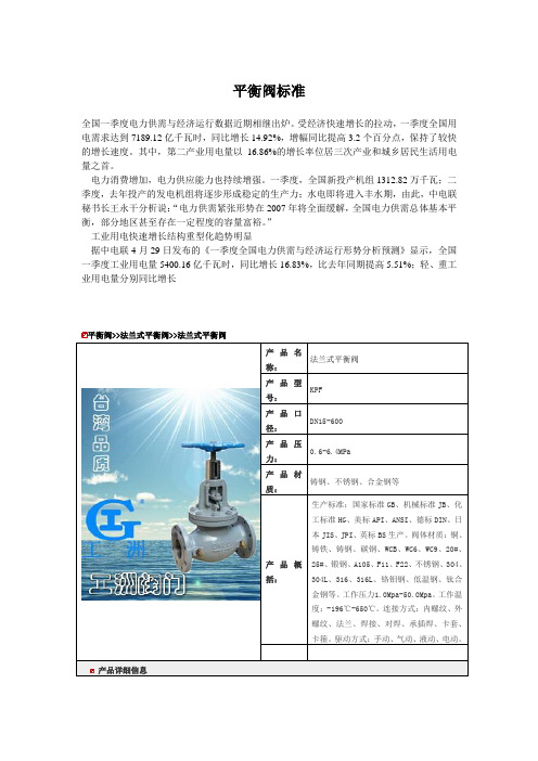
平衡阀标准
平衡阀标准全国一季度电力供需与经济运行数据近期相继出炉。
受经济快速增长的拉动,一季度全国用电需求达到7189.12亿千瓦时,同比增长14.92%,增幅同比提高3.2个百分点,保持了较快的增长速度。
其中,第二产业用电量以16.86%的增长率位居三次产业和城乡居民生活用电量之首。
电力消费增加,电力供应能力也持续增强。
一季度,全国新投产机组1312.82万千瓦;二季度,去年投产的发电机组将逐步形成稳定的生产力;水电即将进入丰水期,由此,中电联秘书长王永干分析说:“电力供需紧张形势在2007年将全面缓解,全国电力供需总体基本平衡,部分地区甚至存在一定程度的容量富裕。
”工业用电快速增长结构重型化趋势明显据中电联4月29日发布的《一季度全国电力供需与经济运行形势分析预测》显示,全国一季度工业用电量5400.16亿千瓦时,同比增长16.83%,比去年同期提高5.51%;轻、重工业用电量分别同比增长平衡阀>>法兰式平衡阀>>法兰式平衡阀产品名称:法兰式平衡阀产品型号:KPF产品口径:DN15-600产品压力:0.6-6.4MPa产品材质:铸钢、不锈钢、合金钢等产品概括:生产标准:国家标准GB、机械标准JB、化工标准HG、美标API、ANSI、德标DIN、日本JIS、JPI、英标BS生产。
阀体材质:铜、铸铁、铸钢、碳钢、WCB、WC6、WC9、20#、25#、锻钢、A105、F11、F22、不锈钢、304、304L、316、316L、铬钼钢、低温钢、钛合金钢等。
工作压力1.0Mpa-50.0Mpa。
工作温度:-196℃-650℃。
连接方式:内螺纹、外螺纹、法兰、焊接、对焊、承插焊、卡套、卡箍。
驱动方式:手动、气动、液动、电动。
产品详细信息0 0 99首页>>产品中心>>截止式流量平衡阀一、产品[截止式流量平衡阀]的详细资料:产品型号:KPF产品名称:截止式流量平衡阀产品特点:平衡阀是一种具有特殊功能的阀门。
新版全国工业阀门工商企业公司商家名录名单联系方式大全20家

河南省濮阳市市辖区 昆吾路与中原路交叉 口西南角馨雅花园8 号中单元二楼西
河南省濮阳市市辖区昆吾路与中 原路交叉口西南角馨雅花园8号 中单元二楼西,法定代表人为王 军,经营范围包括批发零售:水 性漆及涂料,五金工具,劳保用
品,文体用品,阀门管件,柴油
机配件,电动工具
河南泰航液压设备 有限公司
河南
新乡
发区翠竹街76号11 系统设备的销售,维修,技术服
号楼1单元12层
务,软件开发,仪器仪表,阀
12023号
门,泵,电子元器件
河南裕泽工业科技 有限公司
河南
洛阳
河南省洛阳市涧西区 西苑路原河科大门面 房19号
矿山配件,矿山设备,环保设备 的设计,安装及销售,工具,化 工原料,机械设备,机械配件, 金属材料,耐火材料
术产业开发区莲花街 备,安防设备,水泵,阀门,压
338号2号楼10层 缩机的销售,安装,调试,维
106室
修,技术开发
河南元特机械科技 有限公司
河南
郑州
郑州高新技术产业开 发区银屏路15号16 幢1单元16层545号
制药设备,发酵设备,食品饮料 设备,化工设备,环保设备,水 处理设备,空气净化设备,空调 设备,消防设备,制冷设备
钢材,建材,金属制品,有色金 属,机械设备及配件,电力设备 及配件,电线电缆,仪器仪表, 阀门管件,化工原料及产品
河南金品机电设备 有限公司
河南
焦作
河南金品机电设备有限公司成立
于2019年09月23日,注册地位
于孟州市西虢镇落驾头村S238省
孟州市西虢镇落驾头 道旁,法定代表人为李恩宏,经
村S238省道旁
备,机电设备
河南金秋电气有限 公司
SMC电磁阀工作原理

S MC MC电磁阀工作原理电磁阀工作原理电磁阀SMC电磁阀是用来控制流体的自动化基础元件,属于执行器;并不限于液压,气动.电磁阀用于控制液压流动方向,工厂的机械装置一般都由液压钢控制,所以就会用到电磁阀.电磁阀是用电磁控制的工业设备,用在工业控制系统中调整介质的方向,流量,速度和其他的参数.电磁阀有很多种,不同的电磁阀在控制系统的不同位置发挥作用,最常用的是单向阀,安全阀,方向控制阀,速度调节阀等.电磁阀是用电磁的效应进行控制,主要的控制方式由继电器控制.这样,电磁阀可以配合不同的电路来实现预期的控制,而控制的精度和灵活性都能够保证.图中杆状的物体就是通过电控制的阀杆,利用电磁力可以将阀杆打开或者关闭.下面以气动系统为例子说明电磁阀在工业控制中的应用.所谓气动系统,就是以气体为介质的控制系统.气动系统中,这种能源的介质通常就是空气.在真正使用的时候,通常把大气中的空气的体积加以压缩,从而提高它的压力.压缩空气主要通过作用于活塞或叶片来作功.气动系统中,电磁阀的作用就是在控制系统中按照控制的要求来调整压缩空气的各种状态,气动系统还需要其他元件的配合,其中包括动力元件,执行元件,开关,显示设备及其它辅助设备.动力元件包括各种压缩机,执行元件包括各种气缸.这些都是气动系统中不可缺少的部分.而阀体是控制算法得以实现的重要设备.比如单向阀让压缩空气从压缩机进入气罐,当压缩机关闭时,阻止压缩空气反方向流动;安全阀当储气罐内的压力超过允许限度,可将压缩空气排出;方向控制阀通过对气缸两个接口交替地加压和排气,来控制运动的方向;速度调节阀能简便实现执行元件的无级调速.气路系统:油路系统:冷冻系统:A进气过滤器J油箱PB冷冻压缩机空气进气阀K恒温旁通阀Q冷凝器C压缩机主机L油冷却器R热交换器D单向阀M油过滤器S旁通系统EF空气/油分离器N回油阀T 空气出口过滤器最小压力阀O断油阀G后冷却器H带自动疏水器的水分离器气动系统的示意图电磁阀不但能够应用在气动系统中,在油压的系统,水压的系统中也能够得到相同或者类似的应用,比如低功率不供油小型电磁换向阀,密封件不需供油,排出的气体不会污染环境,可用于食品,医药,电子等行业.电磁换向阀现在,电磁阀技术与控制技术,计算机技术,电子技术相结合,已经能够进行多种复杂的控制.比如可以把电磁阀应用在智能控制领域,应用在无线控制技术等方面.电磁阀正是因为能够用电磁进行控制,所以它能与现在的各种电子系统很好地接口,这也是它得到广泛应用的一个主要原因.电磁阀已经广泛地应用在生产的各个领域中,随着电磁控制技术和制造工艺的提高,电磁阀能够实现更加精巧的控制,为实现不同的气动系统,液压系统发挥它的作用.电磁阀的工作原理:电磁阀的工作原理:电磁阀里有密闭的腔,在的不同位置开有通孔,每个孔都通向不同的油管,腔中间是阀,两面是两块电磁铁,哪面的磁铁线圈通电阀体就会被吸引到哪边,通过控制阀体的移动来档住或漏出不同的排油的孔,而进油孔是常开的,液压油就会进入不同的排油管,然后通过油的压力来推动油刚的活塞,活塞又带动活塞杆,活塞竿带动机械装置动.这样通过控制电磁铁的电流就控制了机械运动.电磁阀的结构原理:一:直动式电磁阀有常闭型和常开型二种.常闭型断电时呈关闭状态,当线圈通电时产生电磁力,使动铁芯克服弹簧力同静铁芯吸合直接开启阀,介质呈通路;当线圈断电时电磁力消失,动铁芯在弹簧力的作用下复位,直接关闭SMC电磁阀有什么作用之处,阀口,介质不通.结构简单,动作可靠,在零压差和微真空下正常工作.常开型正好相反.如小于φ6流量通径的电磁阀.二,分步直动式电磁阀该阀采用一次开阀和二次开阀连在一体,主阀和导阀分步使电磁力和压差直接开启主阀口.当线圈通电时,产生电磁力使动铁芯和静铁芯吸合,导阀口开启而导阀口设在主阀口上,且动铁芯与主阀芯连在一起,此时主阀上腔的压力通过导阀口卸荷,在压力差和电磁力的同时作用下使主阀芯向上运动,开启主阀介质流通.当线圈断电时电磁力消失,此时动铁芯在自重和弹簧力的作用下关闭导阀孔,此时介质在平衡孔中进入主阀芯上腔,使上腔压力升高,此时在弹簧复位和压力的作用下关闭主阀,介质断流.结构合理,动作可靠,在零压差时工作也可靠.如:ZQDF,ZS,2W等。
MASCOT产品选型样本

201 支架 202 气缸 210 调节螺钉 211 执行机构推杆 213 行程刻度牌 225 活塞 227 弹簧扣 228 执行机构推杆垫片 229 弹簧 248 调节螺钉垫片 249 阀杆夹 253 支架衬套 256 固定环 271 活塞O形环 272 活塞推杆O形环 274 支架O形环 275 执行机构推杆O形环 348 执行机构推杆锁紧螺母
锻造
锻造车间的能力包括落锤锻造和自由锻造直径最大至1000mm的各种标准材料 和特殊材料,制造成阀盖、法兰、阀塞和阀座环。
配合
诸如大型加工中心和数控机床(CNC)等扩展 设备能够生产各种不同尺寸的阀组件。
涂装
可以满足各种不同的涂装要求,比如标准涂装、用于海上服务的厚涂层涂装,以及用 于高温场合的涂装要求。
MASCOT Industrial 15A Randor Street Campbellfield, Victoria 3061 Australia
Tel: +61 3 9357 6555 | Fax: +61 3 9357 6566 Email: sales@ | Web: 本手册仅供信息参考,我们会努力确保资料的准确性和所提供技术规格的精确度, 但手册内容不作为对 于产品本身的解释或担保。MASCOT Industrial保留对产品设计的更改或改进的权力,本手册中产品信息 和技术规格如有变更,恕不另行通知。MASCOT Industrial对产品的选型,使用和维护不予负责。产品的
高端技术 紧密关断
澳大利亚的制造能力
高可靠性 值得信赖
Page 2
源自澳大利亚的制造能力
MASCOT公司所具有的源自澳大利亚的制造能力包括针对困难工况,应用多种 材料和特殊设计,制造压力等级为ASME CL150至CL4500,尺寸范围由0.5” 至36”的球阀以及2.0”至48”的旋转阀(蝶阀、V形球阀、偏心旋塞阀)。 澳大利亚企业利用供应商合作关系来完成铸件的生产和阀组件的加工 这使加工车间的工作量更具弹性并且大大减少了生产交付周期。 与合作伙伴迄今二十年的合作使MASCOT公司在高品质和及时交付表现上取得 了有证明的良好记录。
Fisher GX 三通阀和执行机构维护手册说明书

Fisher ® GX三通阀和执行机构目录介绍.......................................................................1手册范围................................................................1说明.......................................................................1规格.......................................................................2阀门安装.....................................................................2维护.............................................................................3执行机构维护.........................................................5填料维护................................................................7更换填料................................................................8阀内件维护..........................................................10成套零件...................................................................13零件清单. (14)介绍手册范围该指导手册包括Fisher ® GX 三通阀和执行机构的安装、维护及零件信息。
S系列双瓣气闸阀DoubleFlapAirlockValve安装和维护手册S
e-mail: info@ international calls: 1.518.563.4640 USA/domestic calls: 1.800.352.1731 7 White Street, Plattsburgh, NY USA 12901
第一批双瓣气闸阀(Double Flap Airl问题、以及为处理水泥渣而在1960年代和1970年 代设计制造的。1980年代,为解决美国各地所建电厂的飞灰处理问题,普拉特考公司的气 闸阀售给奥格登·马丁(Ogden Martin)和美国补给燃料(American Refuel) 等公司,并成为这些公司的标准件。
普拉特考(Plattco)公司 / 安装和维护手册
简介
第3 页
本手册包含如何装配、安装、运行和保养普拉特考双瓣气闸阀(Plattco Double Flap Airlock® Valve)的说明。
• 普拉特考双瓣气闸阀的设计旨在便于安装和维护以及长期无故障服务。 • 普拉特考阀门可自动运行,所需维护量少。 装配 • 普拉特考双瓣气闸阀一般在运送时已装配完毕,可在工作地点马上安装。 • 只有在运输条件不允许整件运送的情况下,才会将阀门分解运送。 • 在分解运送的情况下,会提供装配特别说明。 • 收到阀门时,应检查确认在运输途中没有损坏。 保修 所有普拉特考双瓣气闸阀在启用后一年或发运日期之后最长18个月内享有保修。 如有关于保修条款或期限的问题,请与普拉特考公司联系。518-563-4640
普拉特考公司历史
第1 页
普拉特考公司专长瓣阀和滑动闸阀的工程设计和制造,用以解决众多工业应用中的固体材 料输送、加工、测量和隔离等问题。
平衡阀的种类
平衡阀的种类一季度,国家电网公司经营区域电力供需总体基本平衡,发电利用小时数有所减少,累计平均利用小时为1188小时,比上年同期降低66小时。
其中,火电设备平均利用小时为1316小时,比上年同期降低75小时。
一季度,除四川、湖北等局部地区外,国家电网公司经营区域内电力供需形势较2006年同期明显缓和,电力供需总体基本平衡。
国家电网公司各级电网运行平稳,圆满完成了春节和两会期间的保电工作,没有发生重大及以上人身、电网和设备事故。
中国港口协会加大进口铁矿石港口价格自律力度近日,中国港口协会就进口铁矿石港口价格等问题召开会议。
来自全国主要沿海港口企业等26家单位的代表参加了此次会议。
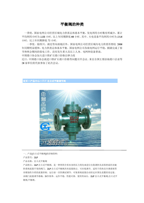
首页>>产品中心>>ZLF自立式平衡调节阀一、产品[自立式平衡阀]的详细资料:产品型号:ZLF产品名称:自立式平衡阀产品特点:ZLF自立式平衡阀,是一种利用介质本身的压力变化来进行自我调控从而保持流经该被控系统流量不变的阀门,ZLF自立式平衡阀具有流量指示,可在线调节,适用于供热及空调系统等非腐蚀性介质的流量控制。
运行前一次性测试调节,可使系统流量自动恒定在预先设置的设定值。
该阀门流量调节准确,操作简单,运作平稳,性能可靠,使用寿命长。
ZLF自立式平衡阀,自立式平衡阀,平衡阀。
二、ZLF自立式平衡阀参数:1.公称压力:1.6MPa2.公称通径:15~350mm3.适用介质:水、油等非腐蚀性液体4.适用温度:0~100℃5.法兰标准:GB/T 17241.6GB/T 91136.试验标准:GB/T 13927API5987.主要零部件材料三、自立式平衡阀材质参考:零件名称材料阀体、阀盖灰铸铁、球铁、铸钢阀杆不锈钢阀瓣铸铜膜片丁腈橡胶四、ZLF自立式平衡调节阀主要外形连接尺寸:D N 152025324565811251520250 300 350 备注L 11111151622152327529313543520 635 670DN15~25为螺纹连接H 1 7272811813813814317193208254289325 357 372H 2 770749114714715418921122726303367 430 495流量0.10.1~1.0.20.51~2~3~5~115~530~840~1100~30150~500200~700m 3/ h ~15 ~2~46 11525~350 0 80 0订货须知:一、①ZLF自立式平衡调节阀产品名称与型号②ZLF自立式平衡调节阀口径③ZLF自立式平衡调节阀是否带附件二、若已经由设计单位选定公司的ZLF自立式平衡调节阀型号,请按ZLF自立式平衡调节阀型号三、当使用的场合非常重要或环境比较复杂时,请您尽量提供设计图纸和详细参数,相关产品:ZZWPE自力式电控温度调节阀ZZYP自力式压力调节阀ZZWP型自力式温度调节阀首页>>产品中心>>KPF型平衡阀一、产品[平衡阀]的详细资料:产品型号:KPF-16型产品名称:平衡阀产品特点:本厂生产的KPF一16型平衡阀是一种具有特殊功能的阀门,具有良好的流量特性,能够合理的分配流量,实现流量定量,可以有效地解决供热(空调)系统中存在的室温冷热不匀问题。
苏州西氟阀门集团有限公司介绍企业发展分析报告模板
Enterprise Development专业品质权威Analysis Report企业发展分析报告苏州西氟阀门集团有限公司免责声明:本报告通过对该企业公开数据进行分析生成,并不完全代表我方对该企业的意见,如有错误请及时联系;本报告出于对企业发展研究目的产生,仅供参考,在任何情况下,使用本报告所引起的一切后果,我方不承担任何责任:本报告不得用于一切商业用途,如需引用或合作,请与我方联系:苏州西氟阀门集团有限公司1企业发展分析结果1.1 企业发展指数得分企业发展指数得分苏州西氟阀门集团有限公司综合得分说明:企业发展指数根据企业规模、企业创新、企业风险、企业活力四个维度对企业发展情况进行评价。
该企业的综合评价得分需要您得到该公司授权后,我们将协助您分析给出。
1.2 企业画像类别内容行业空资质空产品服务:特种设备制造;民用核安全设备制造;民用核1.3 发展历程2工商2.1工商信息2.2工商变更2.3股东结构2.4主要人员2.5分支机构2.6对外投资2.7企业年报2.8股权出质2.9动产抵押2.10司法协助2.11清算2.12注销3投融资3.1融资历史3.2投资事件3.3核心团队3.4企业业务4企业信用4.1企业信用4.2行政许可-工商局4.3行政处罚-信用中国4.4行政处罚-工商局4.5税务评级4.6税务处罚4.7经营异常4.8经营异常-工商局4.9采购不良行为4.10产品抽查4.11产品抽查-工商局4.12欠税公告4.13环保处罚4.14被执行人5司法文书5.1法律诉讼(当事人)5.2法律诉讼(相关人)5.3开庭公告5.4被执行人5.5法院公告5.6破产暂无破产数据6企业资质6.1资质许可6.2人员资质6.3产品许可6.4特殊许可7知识产权7.1商标信息最多显示100条记录,如需更多信息请到企业大数据平台查询7.2专利7.3软件著作权7.4作品著作权7.5网站备案7.6应用APP7.7微信公众号8招标中标8.1政府招标8.2政府中标8.3央企招标8.4央企中标9标准9.1国家标准9.2行业标准9.3团体标准9.4地方标准10成果奖励10.1国家奖励10.2省部奖励10.3社会奖励10.4科技成果11 土地11.1大块土地出让11.2出让公告11.3土地抵押11.4地块公示11.5大企业购地11.6土地出租11.7土地结果11.8土地转让12基金12.1国家自然基金12.2国家自然基金成果12.3国家社科基金13招聘13.1招聘信息感谢阅读:感谢您耐心地阅读这份企业调查分析报告。
grundfos prv压力释放阀安装和使用说明书

GRUNDFOS说明书PRVPressure relief valves安装和使用说明书Other languages/qr/i/96681525中文 (CN)2中文 (CN) 安装和使用说明书翻译原来的英文版这些安装与操作指导对格兰富PRV(泄压阀)进行了说明。
章节1-4介绍了以安全的方式安装和启动本产品所需的信息。
章节5-10介绍了有关产品的重要信息,以及有关服务、故障查找和产品处置的信息。
目录页1. 概述1.1 目标人群本文档适用于运营公司和用户。
在产品安装前以及产品操作和检修过程中必须遵守本手册中规定的一般安全说明。
负责人员在对产品进行任何操作之前必须阅读这些说明。
1.1.1 资格和培训负责本文档所述任务的人员必须具有相关资质。
1.1.2 运营公司的义务•遵守地方安全规章。
•请始终在安装地点放置安装与操作指导,以供随时查阅。
•按照章节9.技术参数的说明协调安装位置的准备。
•确保用户经过针对相关任务的培训。
•提供规定的安全设备和个人防护设备。
•安排定期维护。
1.1.3 用户责任•遵守公认的健康和安全规定以及本地事故预防规定。
•在操作产品和处理化学品时,按照当地健康和安全规定穿戴防护装备。
•阅读并理解本文档。
1.2 安全运行如果阀门已经无法保证安全运行,必须将产品从系统中解除并保证不会被意外地再次用于运行。
以下情况属于上述说明:•产品出现明显可见的损坏。
•如果产品看起来无法操作。
•在恶劣的条件下存放了较长的时间。
1.概述21.1目标人群21.1.1资格和培训21.1.2运营公司的义务21.1.3用户责任21.2安全运行21.3本文献中所用符号32.安装产品32.1位置32.2机械安装32.2.1安装要求32.2.2安装示范32.2.3泄压阀高达460 l/h 42.2.4泄压阀DN 6543.调试产品43.1设置泄压压力43.1.1最佳安装53.1.2其他安装54.搬运和储存产品54.1搬运产品54.2储存产品55.产品介绍55.1设计用途55.1.1不恰当的操作方法55.2型号55.2.1铭牌(泄压阀从60到460 l/h)55.2.2型号66.维护产品76.1维护日程76.2清洁处理76.3更换隔膜77.配件77.1联接螺母适配器(高达460 l/h)77.2用于泄压阀DN 65的一组对接法兰78.故障查找89.技术参数89.1允许介质温度89.2存放温度与环境温度89.3泄压阀高达60 l/h 89.3.1技术参数89.3.2材料89.3.3尺寸图89.4泄压阀从60到460 l/h 99.4.1技术参数99.4.2材料99.4.3尺寸图99.5泄压阀DN 65109.5.1技术参数109.5.2尺寸图1010.产品废弃10开始安装前,请先阅读本文件。
西德福液压件(上海)有限公司北京分公司企业信用报告-天眼查
截止 2018 年 10 月 19 日,根据国内相关网站检索及天眼查数据库分析,未查询到相关信息。不排除因信 息公开来源尚未公开、公开形式存在差异等情况导致的信息与客观事实不完全一致的情形。仅供客户参 考。
4.3 核心团队
截止 2018 年 10 月 19 日,根据国内相关网站检索及天眼查数据库分析,未查询到相关信息。不排除因信 息公开来源尚未公开、公开形式存在差异等情况导致的信息与客观事实不完全一致的情形。仅供客户参 考。
考。
1.3 变更记录
序号
1
变更项目
经营场所
2
负责人
变更前内容
变更后内容
变更日期
北京市西城区宣武门西大街甲 北京市丰台区南四环西路 186 号一区 2016-08-09
129 号金隅大厦 1216 室
1 号楼 2 层 08 单元
吉龙·冯德维尔(Jeroen van 荷尔暮特·阿伦斯(HELMUT AHRENS) 2013-06-19
5.5 行政处罚
截止 2018 年 10 月 19 日,根据国内相关网站检索及天眼查数据库分析,未查询到相关信息。不排除因信 息公开来源尚未公开、公开形式存在差异等情况导致的信息与客观事实不完全一致的情形。仅供客户参 考。
组织机构代码: 565781246
企业类型:
分公司
所属行业:
批发业
经营状态:
开业
注册资本:
/
注册时间:
2010-11-25
注册地址:
北京市丰台区南四环西路 186 号一区 1 号楼 2 层 08 单元
营业期限:
2010-11-25 至/
经营范围:
销售总公司生产的产品。(依法须经批准的项目,经相关部门批准后依批准的内容开展经营活动。)
COAX
德国COAX阀
德国Coax阀有着45年的研发历史,适用于各种对产品质量要求非常高而环境非常恶劣的工业场合。
Coax阀具有20000多不同型号的阀,能函盖所有的工业应用场合,是企业控制、调节、监控工业介质的坚实伙伴。
上海秋腾贸易有限公司优惠供应COAX阀。
德国COAX以生产同轴阀著称,凭借丰富的经验,可靠而经过严格测试的材质,过硬的质量管理,已代表了工程、制造专业以及创新工艺方案的最高技术。
CO-AX已将同轴阀发展成为用于控制真空气态、液态、凝胶状、有颗粒、高污染和强腐蚀性介质的可靠产品。
COAX 同轴阀的设计与普通阀门相比,具有在高流量工况下控制高压的特点。
并能提供二位二通或二位三通的形式,有螺纹或法兰连接方式。
阀门可通过直动电磁阀或外部驱动。
COAX阀门用于控制、调节和止回,适合各种介质,包括从低到高粘性的,从润滑到有颗粒的,从化学性能中性到强腐蚀的,COAX阀门都能应对自如,而且保证质量不变,标准最高。
COAX 核心产品有XX COAX电磁阀、XXCOAX电动调节阀、XX-COAX气动调节阀、XX COAX 自力式调节阀、XXCOAX温度调节阀、COAX压力调节阀、COAX电动球阀、COAX气动球阀、COAX电动蝶阀、COAX气动蝶阀及真空泵、COAX、CO-AX、COAX电磁阀、coax 电动调节阀、coax同轴阀、coax真空发生器、coax阀、coax气动蝶阀、coax阀门。
德福DFFS-5X风冷冷热水剖析
风冷冷热水机组功能说明书DFFS-5X德福电子编制:审核:一.概述DFFS-5X控制器适用于风冷式冷(热)水机组,可以控制单台或2台压缩机,控制器由室外主板和室内线控器组成,并有风盘联动接口。
二.主要技术参数1﹑使用条件□运行电压: AC220V±10%□运行环境温度: -20~+55℃□储存温度: -35~+85℃□湿度要求: 0~95%RH2﹑温度控制精度: 1℃3﹑控制器符合□ GB4706.1-1988《家用和类似用途电器的安全第一部分:通用要求》□ GB4706.32-1996《家用和类似用途电器的安全热泵﹑空调器和除湿机的特殊要求》□GB18430.1-2001《蒸汽压缩机循环冷水(热泵)机组工商业用和类似用途的冷水(热泵)机组》□GB18430.2-2001《蒸汽压缩机循环冷水(热泵)机组户用和类似用途的冷水(热泵)机组》□抗干扰度符合GB4343.2-1999□印刷电路板符合GB4588.1和GB4588.2的规定三.控制器功能1、制冷运行2、制热运行3、可显示回水温度及设置温度,具有查询功能4、掉电自动记忆各种参数5、压缩机均衡运行及分时启动6、三相缺相,逆相保护7、具有完善的保护功能及显示8、具有风盘联动接口9、选用摩托罗拉高性能芯片,抗干扰性能达到最好10、具有定时开关机功能11、具有催款功能四.面板操作室内线控器面板如图一1﹑开关机□按“运转/停止”键,机组开机,指示灯亮;□再按“运转/停止”键,机组关闭,指示灯灭。
□开机,关机均存储数据。
2﹑模式转换□按“模式”键,选择所需的模式,“制冷”“制热”模式□“制冷”模式显示雪花符号□“制热”模式显示太阳符号3﹑定时开关机(1)设置〖b7〗设置为0时是组合定时(设置请参阅下面设置章节)□开机状态下,按“定时”键,定时关机;□关机状态下,按“定时”键,定时开机;□按“定时”键后,小时时间闪显;□按“时间▽△”键,调整小时定时时间□再按“定时”键后,分钟时间闪显;□按“时间▽△”键,调整分钟定时时间□再按“定时”键,定时设定完成□再按“定时”键,则取消定时(2)设置〖b7〗设置为1时是循环定时□按“定时”键后,小时时间闪显,开始设定定时开时间;□按“时间▽△”键,调整小时定时开时间□再按“定时”键后,分钟时间闪显;□按“时间▽△”键,调整分钟定时开时间□再按“定时”键,小时时间闪显,定时开时间设定完毕,开始设定定时关时间;□按“时间▽△”键,调整小时定时关时间□再按“定时”键后,分钟时间闪显;□按“时间▽△”键,调整分钟定时关时间□按“定时”键,定时关时间设定完成(3)时钟设定□按住“定时”键5秒键后,小时时间闪显,进入时钟设定状态;□按“时间▽△”键,调整小时时钟□再按“定时”键后,分钟时间闪显;□按“时间▽△”键,调整分钟时钟□再按“定时”键,时钟设定完成4﹑查询□循环定时(〖b7〗设置为1)时,按“查询”键可显示实时时间。