钢结构喷漆系统714规范 (纯英文)
油漆专业英语
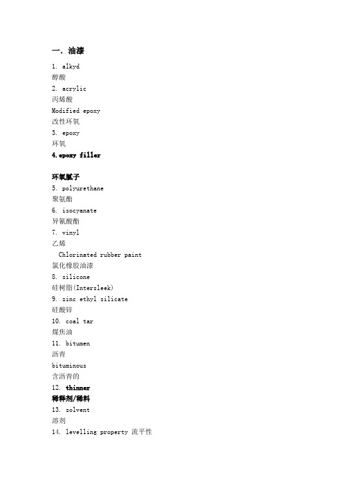
一.油漆1. alkyd醇酸2. acrylic丙烯酸Modified epoxy改性环氧3. epoxy环氧4.epoxy filler环氧腻子5. polyurethane聚氨酯6. isocyanate异氰酸酯7. vinyl乙烯Chlorinated rubber paint 氯化橡胶油漆8. silicone硅树脂(Intersleek)9. zinc ethyl silicate硅酸锌10. coal tar煤焦油11. bitumen沥青bituminous含沥青的12. thinner稀释剂/稀料13. solvent溶剂14. levelling property 流平性15.atomization雾化16.sagging流挂17.cracking龟裂(较重/大)18.checking龟裂(较轻/小)19.blistering起泡20.detachment/ peeling off剥落21. chalking粉化22.overspray过喷23.dry spray干喷24.overlap重叠/搭接25.atomization雾化26.leveling property流平性27. CDP A/F= control depletion polymer A/F 控制消耗聚合物防污漆 (BQ)28. SPC A/F=self polishing copolymerA/F自抛光共聚物防污漆(BE)二.新造船术语1.Primary surface preparation and shop primer application初始表面处理和车间底漆施工2.Steel cutting钢板切割3.Plate bending/fairing and block sub-assembly - curved panel line板材弯曲/校正及分段次组装--曲板线4.Block assembly - flat panel line分段组装--平板线5.Block painting分段涂装6.Pre-erection/grand block assembly预合拢/大分段组装7.Block join up - secondary surface preparation and painting分段合拢--二次表面处理和涂装8.Building dock/building slipway造船坞/造船台9.Vessel launch, quayside outfitting and painting and vessel Delivery船舶下水, 码头舾装和涂装以及交船10.PDD=Pre-Delivery Drydocking= 交船前进坞11.Millscale氧化皮12. Oxy fuel cutting—propane丙烷, acetylene乙炔13.Plasma cutting等离子切割14.laser cutting激光切割15.sharp edge锐边16. Weld spatter焊接飞溅17. Weld slag焊渣18. lamination轧制夹层/迭片二.修船术语A. 船员称呼1.Superintendent机务代表Owner’s representative船东代表2.Capt.=Captain=Master船长3.C/O=chief officer大副4.2/O=second officer二副5.Radio offier电报员6.C/E=chief engineer老轨;轮机长7.2/E=second engineer二轨;8.Bosun=boatswain水手长9.carpenter木匠10.Seaman水手11.dock master坞长12.pilot引水员B. 船舶部位1.Bow船头2.Bulbous bow球鼻艏3.Bow thruster艏侧推4.Midship船舯5.Stern船尾6.E/R=engine room机舱间7.Port左/左舷8.Starboard右/右舷9.Forecastle艏甲板10.poopdeck尾甲板11.hawse锚链孔12.Tweendeck二层甲板13.superstructure / accommodation 上层建筑/ 生活区14.Bulwark舷墙15.gangway舷梯16.scupper(舷侧)流水口17.drain hole排水孔18.draught=draft吃水深度19.draught/draft marks 吃水标记20.topside / freeboard干舷21.Boottop=boottopping水波/水线间22.Vertical bottom/vertical sides直底/直侧面23.flats=flat bottom平底24.shell / hull船壳25.rudder舵26.propeller推进器/螺旋桨27.lifebuoy救生圈28.lifejacket救生衣29.lifeboat救生艇30.davit吊艇柱Skates吊艇架31.Derrick/boom吊杆/吊臂32.derrick clutch/derrick rest /boom rest吊杆/吊臂支架33.hatch cover舱口盖34.hatch coaming舱口围35.holds/cargo holds货舱36.corrugated bulkhead 波形/槽形舱壁37.cofferdam隔离藏38.void space空舱39.TST=topside tanks= 顶边舱/上边舱40.lower slope tanks下边舱41.tank top舱底42.ceiling/deck underneath 反顶43.fender碰垫/护舷材44.dolphin系缆桩,岸桩45.bollard双系缆桩46.OBM=onboard maintenance 在船保养47.floating dock浮坞48.dry dock干坞Tank Coating Systems1 喷砂前的钢结构表面处理Condition of steelwork prior to gritblasting2 通风及湿度控制Moisture control and ventilation3 脚手架/台Scaffolding / staging4 喷砂Grit blasting5 除湿De-humidification6 式玛货油舱涂料的施工Application of Sigma Coatings Tank Coating System7 货油舱上部涂层的检验Inspection of paint system on upper areas8 脚手架的拆除Dismantling and removal scaffolding9 货油舱底部涂层的施工及检验Application and inspection of paint10 舱底漆膜及甲板管道开口涂层的修补Remedial touching up of paint film in tank bottom and coating of ventilation doors and strums11 不锈钢Stainless steel12 海水试验Sea water test1 喷砂前的钢结构表面处理CONDITION OF STEELWORK PRIOR TO GRITBLASTING所有锐边要打磨至半径最少为3毫米的圆角All sharp edges to be ground off to approximately 3.0 millimeters radius as minimum.。
涂装工艺中英文版

涂装工艺中英文版ge1. General 总则 32. Coating System 油漆配套 63. Technical Matters 技术事项 64. Working Procedure For The Cargo Tank Coating 特涂施工程序135. Detail Process 详细工艺过程146. Painting Scheme 油漆明细表257. Inspection 检查258. Specific Requirements For Coating Material 油漆原料的特殊要求269. Coating Sequence 油漆程序2710. Holiday Detection 针孔测试2911. Heat Curing of The Coating System 热固化2912. Salt Water Test & Repair of Defects After Completion 海水浸泡试验及30 修补1.1 The two components SILOXIRANE basedcoating material shall be applied to cargo tank, cargo slop tank and residual oil tank, excluding their outfitting.本双组分油漆的基料为SILOXIRANE,应用于货油舱、货油污油舱和货油泄放舱,不包括它们内部的舾装件。
Tank 舱Quantity 数量Cargo tank货xx油舱Slop tank 货油x污油舱to follow the requirement of the Specificationand this Coating Procedure.涂料制造商进行的检查不减轻船厂遵守技术说明书和特涂工艺的责任。
1.9 The builder shall provide all necessary skilledlabor, tools, equipment and power etc. to carry out the surface preparation, application ofcoating materials and curing of the coatingsystem as specified, to all surfaces of the cargo-, slop- and residual oil tanks.船厂需提供所有必须的熟练工人、工具、设备和动力等,按照规定对货油舱、货油污油舱和货油staging, steel preparation, main blasting,application of coating, inspection, installation of outfitting, curing, salt water testing, etc., shall be provided to the owner’s superintendents prior to the start of the tank coating operations.在特涂施工前,向船东提供一份详细的施工日程计划,内容包括搭脚手、表面处理、主冲砂、油漆作业、交验、舾装件安装、固化、可溶性盐检测等。
目录二-(九)英文版规范

序号 名 称 United standard for building GB/T50001-2001 房屋建筑制图统一标准 Code for design of masonrystructres GB50003-2001 砌体结构设计规范(含局部修订版) Code for design of timbre structures GB50005-2003 木结构设计规范 Code for design of building foundation GB50007-2002 建筑地基基础设计规范 标准号 Load Code for the dedign of building 建筑结构荷载设计规范 Code for design of concrerestructures 混凝土结构设计规范 Code for seismicc design of buildings 建筑抗震设计规范 Structures
GB50016-2006 11 GB50017-2003 12
GB50018 13
GB50019-2003 14 GB50021-2001 15
GBJ22-87 16 GB50026-2007 17
GB50029-2003 18 GB20030-91 19
Code for design of compressed air 压缩空气站设计规范 Code for design of oxygen station 氧气站设计规范
1
2
3
4
GB50009-2001 5 GB50010-2002 6 GB50011-2001 7
GB50013-2006 8
GB50014-2006 9
GB50015-2003 10
钢结构表面喷涂检验标准规范
文件制修订记录1.0目的提供了表面喷涂的技术要求及检验方法。
规定了外观判定的基本方法和客观判定微小缺陷的标准。
以便于统一公司内外标准,减小判定误差。
2.0范围适用于在塑料(包括玻璃钢材料)和金属零件上喷涂处理后的品质要求,外观判定的标准(色调、色彩、性能等)。
3.0测试环境测试环境温度:(23±2)℃,湿度:(50±5)℃。
4.0测试概要试板按GB/T9271标准准备。
1.底材:a)底材与产品要求一致,喷涂工艺和技术要求参照产品要求。
b)底材为马口铁,厚度0.3mm,喷涂工艺和技术要求参照产品要求。
2.数量:底材为a)的准备:10块;底材为b)的准备5块。
3.大小:150mm×200mm。
6.0表面喷涂的技术要求6.1外观要求a)、外观级别分类:喷涂零件的分类标准如下表:对照标准样板,测量色差,要求:△E≤1.0;对照前次供货样板,测量色差,批次色差要求:△E≤0.6c)、光泽检查用BYK光泽仪,以60度角测量,要求:6%±1%d)涂膜外观:涂层表面无漏涂、鼓泡、流挂、皱皮、针孔、渗色、划伤、印痕、褪色、颗粒、脱落、撞伤、色差等缺陷,涂层表面平顺、光滑。
6.2性能要求:a)、附着力要求:在一定破坏力条件下表面不能被揭下来。
测试条件详见7.2.2。
b)、抗磨损要求:在经受一定力度和次数的摩擦后,表面喷涂颜色应无明显变化,表面上的图案不能消失。
测试条件详见7.2.3。
c)柔韧性要求:正向冲击测试后,油漆表面无裂纹、皱纹、脱落现象。
d)、抗溶剂要求:模拟产品在用化学溶剂擦拭后,表面应无褪色、腐蚀或变质等缺陷。
测试条件详见7.2.5。
e)、硬度要求:用规定硬度的铅笔在一定力度下划过表面,产品喷漆表面不应有剥落痕迹。
测试条件详见7.2.6。
f)、耐恶劣气候要求:在一定的高低温、高温高湿条件下产品表面状态不变。
测试条件详见7.2.7。
g)、膜厚要求:喷涂表面应满足设计要求。
ISO12944是规定钢结构的涂层防腐系统的标准

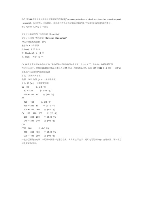
ISO12944是规定钢结构的涂层防腐系统的标准ISO 12944是规定钢结构的涂层防腐系统的标准(Corrosion protection of steel structures by protective paint systems),为工程师、工程顾问、工程承包方以及涂层的供应商提供了全面的有关涂层防腐的指导。
ISO 12944 共分为8 个部分定义了涂装系统的“防腐年限(Durability)”定义了环境的“腐蚀等级(Corrosion Categories)”为选择涂装系统提供了指导表示为 3 个年限低低(Low) 2 至 5 年中(Medium)5 至15 年高(High) 大于15 年C4 H表示腐蚀环境为高盐度的工业地区和中等盐度的海岸地区,比如化工厂,游泳池,海船和船厂等在这种环境下,仅靠电镀或静电喷涂是难以达到15年以上的防腐寿命的,根据ISO12944第 5 部分–防护涂装系统可以进行涂层系统的设计厚度/ 预期防腐年限类别 DFT 范围(μm) (含富锌底漆)最小dft (μm) 预期防腐年限C2 80 低(2-5 年)80 –120 中(5-15 年)160 –200 80 高(>15 年)C3120 –160 低(2-5 年)160 –200 80 中(5-15 年)200 –240 160 高(>15 年)C4 160 –200 160 低(2-5 年)200 –240 200 中(5-15 年)240 –320 240 高(>15 年)C5IC5M 200 低(2-5 年)160 –240 160 中(5-15 年)280 –400 280 高(>15 年)一般涂层系统由底漆,中层漆和面漆三道涂层组成,在此腐蚀环境下,通常选用的油漆有:富锌底漆,环氧中层漆盒聚氨酯面漆。
1. ScopeThis International Standard specifies requirements for thickness corrosion resistance and mechanical and physical properties of non-electrolytically applied zinc flake coatings steel fasteners with metric threads.If applies to both coating with of without chromate.If fasteners with metric thread with pitch below 0.8mm ( 〈 MS )or fasteners with small internal drives or cavities are to be coated. special agreement between supplier and purchaser is required.Coatings according to this international Standard may also be applied to steel screws which from their own mating threads sush as wood screw, self tapping screws,self drilling screw,thread cutting screws and thread rolling screws as well as to non-threaded steel parts sush as washers and pins.They may be similarly applied to steel fasteners with other types of thread.Coatings according to this international Standard can be supplied with integral lubricant and/ or with an externally added lubricant.2. Normative referencesThe following normative documents contain provisionswhich,through reference in thistest,constitute provisions of this international Standard. At the time of publication,the editions indicated were valid. All normative documents are subject to revision. and parties to agreements based on this international Standard are encouraged to investigate the possibility of applying the most recent editions of the normative documents indicated below. For undated references, the latest edition of the normative document referred to applies. Members of ISO and IEC maintain registers of currently valid International Standard.ISO 898-1 :1989Mechanical properties of fastener . Bolts, screws and studs ISO 1502 :1978ISO general purpose metric screw thread-GaugingISO 1463 :1982Metallic and oxide coatings-Measurement of coating thickness-Microscopical methodISO 6988 : 1085Metallic and other non-organic coatings-Sulfur dioxide test with general condensation of moisture ISO 8991 : 1986 Designation system for fastenersISO 9227 : 1990Corrosion tests in artificial atmospheres-salt spray testISO/DIS 15330 : 1997Fasteners-Preloading test for the detection of hydrogen embitterment-Parallel bearing surface method3. DefinitionNon -electrolytically applied zinc flake coating( with or without integral lubricant)A coating which is produced by applying on the surface of a fastener a zinc flakedispersion,possibly with addition of aluminum flakes .in a suitable medium which under influence of heat(curing)generates a bonding of the flakes and between flakes and the substrate thus forming a sufficiently electrically conduction inorganic surface coating to ensure cathode protection. The coating may or may not contain chromate.4. GeneralIt is a characteristic df this type of coating that no hydrogen which could be absorbed by the parts is generated during the coating process. Therefore, by using pretreatment cleaning methods which do not generate nascent hydrogen (for example blast cleaning),there is not risk of hydrogen embitterment form the surface preparation procedure.If cleaning methods are applied which could lead to hydrogen absorption (such as cleaning).then for fasteners which 8 hardness above 365 Hv in process control shall be conducted to ensure that the process with regard to hydrogen embroilment is under control. This can be done by a preload test according to ISO 15330However it should be noted that a non electrolytically applied zinc flake coating has a high permeability for hydrogen which during the curing process, allows effusion of hydrogen which may have been absorbed before the coating process.5.Dimensional requirements and testingThe applicability of coating to ISO metric threads is limited by the fundamental deviation of the threads concerned as given in table 1 and, hence, by the pitch and tolerance positions. The coating shall not cause the zero line(basic size)to be exceeded in the case of external threads, nor shall it fall below in the case of internal threads. this means that for an internal thread oftolerances position H, a measurable coating thickness can only be applied to the thread if the tolerance zone is not taken up to the zero line(basic size).After coating, ISO metric screw threads shall be gauged according to ISO 1502 with a GO-gauge of tolerance position h for external threads and H for internal threads. When gauging the coated thread a maximum torque of 0,001 d3. (N.m)is acceptable, where d is the nominal thread diameter in min.Other product dimensions apply only before coating.NOTE Care should be exercised where relatively thick coatings may affect dimensions with small tolerances such as internal drives or small nuts, in these cases agreements shall be made between the supplier and the purchaser.Table 1 - Theoretical upper limits of coating thickness for ISO metric threadsIf a minimum coating thickness( t min)is required in order to achieve a specified corrosion resistance (see clause 6)the range of the coating thickness has to be taken into consideration which is approximately the same as the minimum coating itself. Therefore the maximum coating thickness to be expected is twiceas much as the required minimum coating thickness see table 2. The minimum fundamental deviation required for a specified minimum coating thickness which is 4 t max (or 8 t min )is also given in table 2.Table 2 -Coating thickness and required fundamental deviationIf for a given pitch the fundamental deviation as given in table 1 is not sufficient to allow for the required minimum coating thickness then.--either the tolerance position of the thread has to be changed ( e.g.f instead of g )--or the tolerance within the given tolerance field has to be restricted such that the threadhas to be manufactured at the upper limit for the internal thread or at the lower limit external thread of the respective tolerance.Required minimum local coating thickness to achieve specified corrosion resistance are given in table 3.If the minimum local coating thickness is specified (see table3) it may be measured by magnetic or X ray techniques. In the case of dispute the referee test shall be the microscopical method as described in ISO 1463. The surfaced to be used for thickness measurements are those given in figure1 Measuring areaFigure 1 --Measuring area for coating thickness measurement on threaded fasteners6 Testing of corrosion protectionThe neutral salt spray test according to ISO9227 is used to evaluate the quality of the coating. The test is applied to coated parts which are in the as delivered condition. Performance in the test cannot be related to corrosion protection behavior in particular service environments.NOTE In normal cases the coating shall be defined by specifying the test duration for neutral salt spray test according to table 3. see example 1 in clause 9.After the neutral salt spray test with a test duration according to table 3 there shall be no visible ferrous(red) corrosion attack on the base metal.Table 3 -- Test duration ( Neutral salt spray test )7. Mechanical and physical properties and testing7.1GeneralThe coating process shall not adversely influence the mechanical and physical properties of fasteners as specified in the relevant ISO Standards.Consideration shall be given by the manufacturer supported by testing if necessary. to determine whether the curing temperature and duration as specified by the coater are suitable foe the particular type of fastener to be coated.7.2 AppearanceThe colour of the coating is silver grey. The coated fastener shall be free from blisters, localized excess coating and uncoated areas which may have adverse effects on corrosion protection and fitness for use.Special techniques may be necessary to avoid excess coating or uncoated areas with parts such as washers. nuts and recess drive screw.7.3 Temperature resistanceAfter heating the coated fasteners for 3 hours at 150℃(part temperature) the corrosion resistance requirements as specified in clause 6 shall still be met.7.4 DuctilityAfter loading the coated fastener with the proof load specified in ISO 898-1 the corrosion resistance as specified in clause 6 shall still be met in areas other than where thread engagement has occurred. This requirement applies to bolts. screws and studs with metric thread only.7.5 Adhesion/ cohesionIf an adhesive tape with an a dhesive strength of (7 N ± 1 N) per 25 mm width is pressed by hand on the surface and is subsequently pulled off jerkily and perpendicularly to the surface.the coating shall not be peeled off the base metal. Small amounts of the coating material sticking on the tape are acceptable.7.6 Cathodic protectionThe cathodic protection capability of the coating can be tested by making the salt spray test according to be clause with a specimen which is scratched to the base metal, the scratch having a width of max.0.5 mm. After the salt spray rest of 72 h there shall be no red rust in the scratched area.7.7 Torque/tension relationship for coatings with integral lubricant or externally added lubricant The requirements for torque/tension shall be agreed between the manufacturer and purchaser.8. Applicability of tests8.1 GeneralAll requirements given in the clause 5, 6 and 7 apply as far as they are general characteristics of the coating or are separately specified by the customer. The tests included in clause 8.2 shall be carried out for each lot of fasteners. The tests included in clause 8.3 are not intended to be applied for each fastener lot, but are used for in process control.8.2 Tests mandatory for each lot--Gauging of threads ( 5 )--Appearance ( 7.2 )--Adhesion/cohesion ( 7.5 )8.3 Tests to be made for in process control--Neutral salt spray test (6)--Temperature resistance ( 7.3 )--Ductility ( 7.4 )--Cathodic protection ( 7.6 )8.4 Tests which are only to be made when specified by the customer-- Coating thickness ( 5 )--Torque/tension relationship for coating with integral lubricant ( 7.7 )9. DesignationThe designation of the coating shall be added to the product designation in accordance with the designation system specified in ISO 8991 using the symbol flZn for non-electrolytically applied zinc flake coating, a figure for the required duration of salt spray test in hours and, if necessary,the specification for a coating with chromate(yc) or without chromate (nc).EXAMPLE 1 Hexagon head bolt ISO 4014 - M12 X 80 - 10.9 with a non-electrolytically applied zinc flake coating(flZc), with a required duration of salt spray test of 480 h:Hexagon head bolt ISO 4014 - M12 X 80 - 10.9 - flZn - 480h if a coating with integral lubricant is required,the letter L shall be added to the designation after the symbol for the zinc flake coating:Hexagon head bolt ISO 4014 - M12 X 80 - 10.9 - flZnL - 480h if a coating with a subsequent lubrication(external lubricant) is required, the letter L shall be added at the of the designation: Hexagon head bolt ISO 4014 - M12 X 80 - 10.9 - flZn - 480h - LEXAMPLE 2 Hexagon head bolt ISO 4014 - M12 X 80 - 10.9 with a non-electrolytically applied zinc flake coating without chromate flZnnc, with a required duration of salt spray test of 480 h:Hexagon head bolt ISO 4014 - M12 X 80 - 10.9 - flZnnc - 480hEXAMPLE 3 Hexagon head bolt ISO 4014 - M12 X 80 - 10.9 with a non-electrolytically applied zinc flake coating with chromate flZnyc, with a required duration of salt spray test of 480 h:Hexagon head bolt ISO 4014 - M12 X 80 - 10.9 - flZnyc - 480h10. Ordering requirementsWhen ordering threaded parts to be coated according to this International Standard, the flowing information shall be supplied to the coater:a) THe reference to this International standard and the coating designation(see clause 9).b) The matrial of the part and its. condition, e.g. heat treatment, hardness ororder properties, which may be influenced by the coating process..c) Thread tolerances if different from the product standardd) Performance(torque/tension, coefficient of friction, sealing) and the testmethods for integrally lubricated or supplementary lubricated coating shallbe agreed between the manufacturer and purchaser.e) Tests to be carried out, if any(see clause 8)f) Sampling。
中英文油漆规范

• Gloss finishing paints are of machine finish grade having high adhesion and high resistance to solvents, mineral oils, cutting oils, detergents, chipping and impact.
SECTION 09900
PAINTING 油漆
Part 1
GENERAL
概述
1.01 1.02
RELATED DOCUMENTS 相关文件
A. Provisions established within the Conditions of the Contract and Division 1 - General Requirements, all Sections of the Specifications, and the Contract Drawings are collectively applicable to this Section. 合同要求,第一篇普通要求和本规范的所有章节的合同图纸
当无特别要求,应按下列要求进行
• Protect all metal work, plant, equipment, pipelines, ducts, ancillaries, brackets and supports against corrosion and oxidisation.
防护所有金属、设备、管线、风管、支架,以防止腐蚀和氧化
地下防腐膜
• Cold applied, non woven synthetic fibre fabric, petroleum based anti corrosion tape 冷施工、非织合成纤维,石油基的防腐带
PSPC涂装规范
GUIDELINE FOR IMPLEMENTATION OFMSC.215(82)PERFORMANCE STANDARD FORPROTECTIVE COATINGS FOR DEDICATED BALLAST TANKS IN ALL TYPES OF SHIPS AND DOUBLE-SIDE SKIN SPACES OF BULK CARRIERSCONTENTS1 Preface (3)2 Definitions (3)3 Application (SOLAS vs IACS) (5)4 General Principle for Inspection (7)5 Qualifications (8)5.1 Coating Inspectors (8)5.1.1 PSPC Requirements (8)5.1.2 Guidance (9)6 Coatings (10)6.1 Coating Systems (10)6.1.1 PSPC Requirements (10)6.1.2 Guidance (14)7 Primary Surface Preparation (PSP) (16)7.1 Blasting (16)7.1.1 PSPC Requirements (16)7.1.2 Guidance (17)7.1.3 Records (17)7.2 Shop Primer Application (17)7.2.1 PSPC Requirements (17)7.2.2 Guidance (18)7.2.3 Records (18)8 Assembly (19)8.1 Steel Surface Preparation (19)8.1.1 PSPC Requirements (19)8.1.2 Guidance (19)8.1.3 Record (19)8.2 Secondary Surface Preparation (SSP) (20)8.2.1 PSPC Requirements (20)8.2.2 Guidance (22)8.2.3 Records (23)8.3 Coating (23)8.3.1 PSPC Requirements (23)8.3.2 Guidance (26)8.3.3 Records (26)9 Others (27)9.1 Verification (27)9.1.1 PSPC Requirements (27)9.1.2 Guidance (29)9.2 Inspection (31)9.2.1 PSPC Requirements (31)9.2.2 Guidance (31)9.3 Annex 3 Dry Film Thickness Measurements (33)9.3.1 PSPC Requirements (33)9.3.2 Guidance (33)9.4 Example Reporting Forms (36)1PrefaceThe purpose of this Guideline is to provide guidance for implementation of “Performance Standard for Protective Coatings for dedicated seawater ballast tanks in all types of ships and double-side skin spaces of bulk carriers (hereinafter referredto as “PSPC”)” referred in the amendments to regulations II-1/3-2 and XII/6 of the International Convention for the Safety of Life at Sea (SOLAS), 1974, as amended adopted by resolution MSC.216 (82).本指南旨在为进行MSC.216(82)会议通过的SOLAS第II-1/3-2和XII/6.条修正案中所引入的PSPC所要求的执行提供指导。
工程刷油漆规范英文
GNL- 3Z Project318800-GNL3Z-SF-PI-00-60709LocationArzew, AlgeriaSh. 1 of 17 Rev. A 0 1 Date 25NOV09 I.D. IFCSPECIFICATION FORFIELD COATING PROCEDURES涂漆规定1 ISSUE FOR CONSTRUCTION M.Beltrami G.Torchia C.Gigante 25NOV090 ISSUE FOR CONSTRUCTION M.Beltrami G.Torchia C.Gigante 20JUL09A ISSUE FOR APPROVAL M.Beltrami G.Torchia C.Gigante 30JAN09 Rev. Description Prepared Checked Approved DateGNL- 3Z Project318800-GNL3Z-SF-PI-00-60709LocationArzew, AlgeriaSh. 2 of 17 Rev. A 0 1 Date 25NOV09 I.D. IFCI N D E X1.0GENERAL (3)1.1Scope (3)1.2 ReferencedDocuments (3)2.0 GENERALPROC EDURES (3)2.1 Plan ofWork (3)2.2 Extent of FieldPainting (3)2.3 Precautions forValves (4)2.4 SurfacePreparation (5)2.5 Solvents andThinners (6)2.6 Paint Code CrossReference (6)2.7 FinishColors (7)2.8 ServiceIdentification (8)3.0 REPAIRPROCEDURES (13)3.1 Damage Exposing Bare Metal orRust (13)3.2 Damage Coating not Exposing Bare Metal orRust ...... (13)3.3 Damage ofGalvanizing... (13)GNL- 3Z Project318800-GNL3Z-SF-PI-00-60709LocationArzew, AlgeriaSh. 3 of 17 Rev. A 0 1 Date 25NOV09 I.D. IFC1.0 一般事项概括1.1 范围1. This standard covers the field coating requirements and supplements the general painting requirementsof Technical Standard 00-GA-E-60708 “General Coating Procedures”.该标准涵盖了区域涂层的要求和补充一般涂层的标准技术00-GA-E-60708 “一般涂料的要求”2. This standard does not cover internal linings, underground piping, or architectural applications.本标准不包括内部衬垫,地下管道,或建筑中的应用。
coating inspection manual中译本

内容节标题1 涂装技术2 油漆检查人员的任务3 技术规范4 分包商的工艺5 怎样监测环境情况6 如何检查所使用的压缩空气7 如何检查循环使用的磨料8 如何检查处理好的钢件表面9 如何测量喷砂处理后钢材的表面粗糙度10 如何测量湿膜的厚度11 如何测量干膜的厚度12 如何检查油漆缺陷13 如何检查露底,针孔及空隙14 如何检查涂层和衬里的附着力15 油漆计算16 术语汇编第一节1.0 涂装技术1.1 腐蚀原理1.1.1什么是腐蚀1.1.2什么会引起腐蚀1.1.3腐蚀发生时环境中必须要有那些要素1.1.4控制腐蚀应使用那些方法1.1.5详细的腐蚀研究有那些推荐读物1.2 油漆,涂料以及喷涂衬里1.2.1油漆与涂料有什么区别1.2.2涂料与衬里有那些一般用途1.2.3常用的涂料有哪些类型1.2.4涂料的基本组成是什么1.2.5稀释剂与溶剂有什么区别1.2.6涂料如何固化1.2.7常用的各类涂料有那些基本的物理和化学特性1.0 涂装技术1.1.1腐蚀原理腐蚀是指材料与环境发生反应而蜕变的过程。
由于钢铁是目前使用最广泛而又易腐蚀的建材,要延长钢结构或设备的寿命,腐蚀控制就非常重要。
由于腐蚀机理非常复杂,详细的腐蚀研究远远超过本手册叙述范围。
但本手册第 1.1.5节提供了一些补充阅读材料以供感兴趣的人员继续研究。
1.1.2什么会引起腐蚀钢铁腐蚀的最基本原因是它们零时的金属存在形式。
这些金属是加工产品,化学性质不稳定。
通过氧化,它们回到开采以前铁矿石的天然形态。
钢铁是通过高炉从铁矿石中提炼而成的。
在变成钢铁的过程中,矿石需要大量的能量。
而其本性却要释放所获取得能量而稳定下来,钢铁就腐蚀而产生铁锈。
1.1.3腐蚀发生时环境中必须要有那些要素铁要腐蚀,环境中必须存在以下三个要素:--氧气--水--离子源这三个要素越集中,腐蚀反应就越快。
1.1.4控制腐蚀应使用那些方法金属腐蚀的倾向是一种自然现象。
我们应认识到这是不可避免的。
钢结构表面喷涂检验标准规范
文件制修订记录
1.0目的
提供了表面喷涂的技术要求及检验方法。
规定了外观判定的基本方法和客观判定微小缺陷的标准。
以便于统一公司内外标准,减小判定误差。
2.0范围
适用于在塑料(包括玻璃钢材料)和金属零件上喷涂处理后的品质要求,外观判定的标准(色调、色彩、性能等)。
3.0测试环境
测试环境温度:(23±2)℃,湿度:(50±5)℃。
4.0测试概要
试板按GB/T9271标准准备。
1.底材:a)底材与产品要求一致,喷涂工艺和技术要求参照产品要求。
b)底材为马口铁,厚度0.3mm,喷涂工艺和技术要求参照产品要求。
2.数量:底材为a)的准备:10块;底材为b)的准备5块。
3.大小:150mm×200mm。
6.0表面喷涂的技术要求
6.1外观要求
a)、外观级别分类:
喷涂零件的分类标准如下表:
对照标准样板,测量色差,要求:△E≤1.0;
对照前次供货样板,测量色差,批次色差要求:△E≤0.6
c)、光泽检查
用BYK光泽仪,以60度角测量,要求:6%±1%
d)涂膜外观:
涂层表面无漏涂、鼓泡、流挂、皱皮、针孔、渗色、划伤、印痕、褪色、颗粒、脱落、撞伤、色差等缺陷,涂层表面平顺、光滑。
ISO 12944是规定钢结构的涂层防腐系统的标准
ISO 12944是规定钢结构的涂层防腐系统的标准(Corrosion protection of steel structures by protective paint systems),为工程师、工程顾问、工程承包方以及涂层的供应商提供了全面的有关涂层防腐的指导。
ISO 12944 共分为8 个部分定义了涂装系统的“防腐年限(Durability)”定义了环境的“腐蚀等级(Corrosion Categories)”为选择涂装系统提供了指导表示为 3 个年限低低(Low) 2 至 5 年中(Medium)5 至15 年高(High) 大于15 年C4 H表示腐蚀环境为高盐度的工业地区和中等盐度的海岸地区,比如化工厂,游泳池,海船和船厂等在这种环境下,仅靠电镀或静电喷涂是难以达到15年以上的防腐寿命的,根据ISO12944第 5 部分–防护涂装系统可以进行涂层系统的设计厚度/ 预期防腐年限类别 DFT 范围(µm) (含富锌底漆)最小dft (µm) 预期防腐年限C2 80 低(2-5 年)80 –120 中(5-15 年)160 –200 80 高(>15 年)C3120 –160 低(2-5 年)160 –200 80 中(5-15 年)200 –240 160 高(>15 年)C4 160 –200 160 低(2-5 年)200 –240 200 中(5-15 年)240 –320 240 高(>15 年)C5IC5M 200 低(2-5 年)160 –240 160 中(5-15 年)280 –400 280 高(>15 年)一般涂层系统由底漆,中层漆和面漆三道涂层组成,在此腐蚀环境下,通常选用的油漆有:富锌底漆,环氧中层漆盒聚氨酯面漆。
1. ScopeThis International Standard specifies requirements for thickness corrosion resistance and mechanical and physical properties of non-electrolytically applied zinc flake coatings steel fasteners with metric threads.If applies to both coating with of without chromate.If fasteners with metric thread with pitch below 0.8mm ( 〈 MS )or fasteners with small internal drives or cavities are to be coated. special agreement between supplier and purchaser is required.Coatings according to this international Standard may also be applied to steel screws which from their own mating threads sush as wood screw, self tapping screws,self drilling screw,thread cutting screws and thread rolling screws as well as to non-threaded steel parts sush as washers and pins.They may be similarly applied to steel fasteners with other types of thread.Coatings according to this international Standard can be supplied with integral lubricant and/ or with an externally added lubricant.2. Normative referencesThe following normative documents contain provisions which,through reference in thistest,constitute provisions of this international Standard. At the time of publication,the editions indicated were valid. All normative documents are subject to revision. and parties to agreements based on this international Standard are encouraged to investigate the possibility of applying the most recent editions of the normative documents indicated below. For undated references, the latest edition of the normative document referred to applies. Members of ISO and IEC maintain registers of currently valid International Standard.ISO 898-1 :1989Mechanical properties of fastener . Bolts, screws and studsISO 1502 :1978ISO general purpose metric screw thread-GaugingISO 1463 :1982Metallic and oxide coatings-Measurement of coating thickness-Microscopical methodISO 6988 : 1085Metallic and other non-organic coatings-Sulfur dioxide test with general condensation of moisture ISO 8991 : 1986Designation system for fastenersISO 9227 : 1990Corrosion tests in artificial atmospheres-salt spray testISO/DIS 15330 : 1997Fasteners-Preloading test for the detection of hydrogen embitterment-Parallel bearing surface method3. DefinitionNon -electrolytically applied zinc flake coating( with or without integral lubricant)A coating which is produced byapplying on the surface of a fastener a zinc flake dispersion,possibly with addition of aluminum flakes .in a suitable medium which under influence of heat(curing)generates a bonding of the flakes and between flakes and the substrate thus forming a sufficiently electrically conduction inorganic surface coating to ensure cathode protection. The coating may or may not contain chromate.4. GeneralIt is a characteristic df this type of coating that no hydrogen which could be absorbed by the parts is generated during the coating process. Therefore, by using pretreatment cleaning methods which do not generate nascent hydrogen (for example blast cleaning),there is not risk of hydrogen embitterment form the surface preparation procedure.If cleaning methods are applied which could lead to hydrogen absorption (such as cleaning).then for fasteners which 8 hardness above 365 Hv in process control shall be conducted to ensure that the process with regard to hydrogen embroilment is under control. This can be done by a preload test according to ISO 15330However it should be noted that a non electrolytically applied zinc flake coating has a high permeability for hydrogen which during the curing process, allows effusion of hydrogen which may have been absorbed before the coating process.5.Dimensional requirements and testingThe applicability of coating to ISO metric threads is limited by the fundamental deviation of the threads concerned as given in table 1 and, hence, by the pitch and tolerance positions. The coating shall not cause the zero line(basic size)to be exceeded in the case of external threads, nor shall it fall below in the case of internal threads. this means that for an internal thread of tolerances position H, a measurable coating thickness can only be applied to the thread if the tolerance zone is not taken up to the zero line(basic size).After coating, ISO metric screw threads shall be gauged according to ISO 1502 with a GO-gauge of tolerance position h for external threads and H for internal threads. When gauging the coated thread a maximum torque of 0,001 d3. (N.m)is acceptable, where d is the nominal thread diameter in min.Other product dimensions apply only before coating.NOTE Care should be exercised where relatively thick coatings may affect dimensions with small tolerances such as internal drives or small nuts, in these cases agreements shall be made between the supplier and the purchaser.Table 1 - Theoretical upper limits of coating thickness for ISO metric threadsIf a minimum coating thickness( t min)is required in order to achieve a specified corrosion resistance (see clause 6)the range of the coating thickness has to be taken into consideration which is approximately the same as the minimum coating itself. Therefore the maximum coating thickness to be expected is twice as much as the required minimum coating thickness see table 2. The minimum fundamental deviation required for a specified minimum coating thickness which is 4 t max (or 8 t min )is also given in table 2.Table 2 -Coating thickness and required fundamental deviationIf for a given pitch the fundamental deviation as given in table 1 is not sufficient to allow for the required minimum coating thickness then.--either the tolerance position of the thread has to be changed ( e.g.f instead of g )--or the tolerance within the given tolerance field has to be restricted such that the thread has to be manufactured at the upper limit for the internal thread or at the lowerlimit external thread of the respective tolerance.Required minimum local coating thickness to achieve specified corrosion resistance are given in table 3.If the minimum local coating thickness is specified (see table 3) it may be measured by magnetic or X ray techniques. In the case of dispute the referee test shall be the microscopical method as described in ISO 1463. The surfaced to be used for thickness measurements are those given in figure1 Measuring areaFigure 1 --Measuring area for coating thickness measurement on threaded fasteners6 Testing of corrosion protectionThe neutral salt spray test according to ISO9227 is used to evaluate the quality of the coating. The test is applied to coated parts which are in the as delivered condition. Performance in the test cannot be related to corrosion protection behavior in particular service environments.NOTE In normal cases the coating shall be defined by specifying the test duration for neutral salt spray test according to table 3. see example 1 in clause 9.After the neutral salt spray test with a test duration according to table 3 there shall be no visible ferrous(red) corrosion attack on the base metal.Table 3 -- Test duration ( Neutral salt spray test )7. Mechanical and physical properties and testing7.1GeneralThe coating process shall not adversely influence the mechanical and physical properties of fasteners as specified in the relevant ISO Standards.Consideration shall be given by the manufacturer supported by testing if necessary. to determine whether the curing temperature and duration as specified by the coater are suitable foe the particular type of fastener to be coated.7.2 AppearanceThe colour of the coating is silver grey. The coated fastener shall be free from blisters, localized excess coating and uncoated areas which may have adverse effects on corrosion protection and fitness for use.Special techniques may be necessary to avoid excess coating or uncoated areas with parts such as washers. nuts and recess drive screw.7.3 Temperature resistanceAfter heating the coated fasteners for 3 hours at 150℃(part temperature) the corrosion resistance requirements as specified in clause 6 shall still be met.7.4 DuctilityAfter loading the coated fastener with the proof load specified in ISO 898-1 the corrosion resistance as specified in clause 6 shall still be met in areas other than where thread engagement has occurred. This requirement applies to bolts. screws and studs with metric thread only.7.5 Adhesion/ cohesionIf an adhesive tape with an a dhesive strength of (7 N ± 1 N) per 25 mm width is pressed by hand on the surface and is subsequently pulled off jerkily and perpendicularly to the surface. the coating shall not be peeled off the base metal. Small amounts of the coating material sticking on the tape are acceptable.7.6 Cathodic protectionThe cathodic protection capability of the coating can be tested by making the salt spray test according to be clause with a specimen which is scratched to the base metal, the scratch having a width of max.0.5 mm. After the salt spray rest of 72 h there shall be no red rust in the scratched area.7.7 Torque/tension relationship for coatings with integral lubricant or externally added lubricant The requirements for torque/tension shall be agreed between the manufacturer and purchaser.8. Applicability of tests8.1 GeneralAll requirements given in the clause 5, 6 and 7 apply as far as they are general characteristics of the coating or are separately specified by the customer. The tests included in clause 8.2 shall be carried out for each lot of fasteners. The tests included in clause 8.3 are not intended to be applied for each fastener lot, but are used for in process control.8.2 Tests mandatory for each lot--Gauging of threads ( 5 )--Appearance ( 7.2 )--Adhesion/cohesion ( 7.5 )8.3 Tests to be made for in process control--Neutral salt spray test (6)--Temperature resistance ( 7.3 )--Ductility ( 7.4 )--Cathodic protection ( 7.6 )8.4 Tests which are only to be made when specified by the customer-- Coating thickness ( 5 )--Torque/tension relationship for coating with integral lubricant ( 7.7 )9. DesignationThe designation of the coating shall be added to the product designation in accordance with the designation system specified in ISO 8991 using the symbol flZn for non-electrolytically applied zinc flake coating, a figure for the required duration of salt spray test in hours and, if necessary,the specification for a coating with chromate(yc) or without chromate (nc).EXAMPLE 1 Hexagon head bolt ISO 4014 - M12 X 80 - 10.9 with a non-electrolytically applied zinc flake coating(flZc), with a required duration of salt spray test of 480 h:Hexagon head bolt ISO 4014 - M12 X 80 - 10.9 - flZn - 480hif a coating with integral lubricant is required,the letter L shall be added to the designation after the symbol for the zinc flake coating:Hexagon head bolt ISO 4014 - M12 X 80 - 10.9 - flZnL - 480hif a coating with a subsequent lubrication(external lubricant) is required, the letter L shall be added at the of the designation:Hexagon head bolt ISO 4014 - M12 X 80 - 10.9 - flZn - 480h - LEXAMPLE 2 Hexagon head bolt ISO 4014 - M12 X 80 - 10.9 with a non-electrolytically applied zinc flake coating without chromate flZnnc, with a required duration of salt spray test of 480 h: Hexagon head bolt ISO 4014 - M12 X 80 - 10.9 - flZnnc - 480hEXAMPLE 3 Hexagon head bolt ISO 4014 - M12 X 80 - 10.9 with a non-electrolytically applied zinc flake coating with chromate flZnyc, with a required duration of salt spray test of 480 h: Hexagon head bolt ISO 4014 - M12 X 80 - 10.9 - flZnyc - 480h10. Ordering requirementsWhen ordering threaded parts to be coated according to this International Standard, the flowing information shall be supplied to the coater:a) THe reference to this International standard and the coating designation(see clause 9).b) The matrial of the part and its. condition, e.g. heat treatment, hardness ororder properties, which may be influenced by the coating process..c) Thread tolerances if different from the product standardd) Performance(torque/tension, coefficient of friction, sealing) and the testmethods for integrally lubricated or supplementary lubricated coating shallbe agreed between the manufacturer and purchaser.e) Tests to be carried out, if any(see clause 8)f) Sampling。
钢构件喷砂与油漆质量要求SteelWorkShotblastPaintingStandard
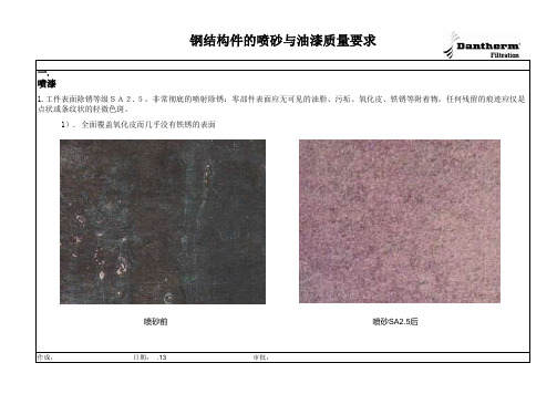
钢结构件的喷砂与油漆质量要求一. 喷漆、喷砂质量一般要求:1.工件表面除锈等级SA2.5,非常彻底的喷射除锈:零部件表面应无可见的油脂、污垢、氧化皮、铁锈等附着物,任何残留的痕迹应仅是点状或条纹状的轻微色斑。
1). 全面覆盖氧化皮而几乎没有铁锈的表面喷砂前喷砂SA2.5后钢结构件的喷砂与油漆质量要求2). 已发生锈蚀,并且部分氧化皮已经剥落的表面喷砂前喷砂SA2.5后作成:日期:2009.8.13审批:3).氧化皮已因锈蚀而剥落,或者可以刮除,并且有少量的点蚀表面喷砂前喷砂SA2.5后4).氧化皮已因锈蚀而全面剥落,并且已普遍发生点蚀的表面喷砂前喷砂SA2.5后1.在喷砂后,喷漆前,工件的外表面和内表面一眼就看到的地方(管道靠近法兰的地方等)要去除焊渣、焊瘤、焊接飞溅物等。
2.喷漆前要清洁工件表面,不得有浮尘、打磨的铁屑等3.工件的外表面有缝的地方和焊接没法焊到或焊接不到位,包括可视的气孔等焊接缺陷,均需要打胶处理(如图20)4.打胶的要求: 1).胶水要均匀,美观。
2).在保证把缝覆盖掉的同时,胶水的量越少越好5.打胶用的胶水为丙烯酸胶。
6.工件的外表面均不得有明显的流挂,漏喷,起皱,起泡,划伤等缺陷.7.颜色:根据油漆规格与样本相比对。
9.涂层厚度 1).涂层厚度要均匀,包括加强筋、边缘和不容易喷到的地方,无脱层和开裂;2).根据油漆规格单,用测厚仪检验漆膜厚度。
厚度误差要求:总面积的90%厚度不低于要求厚度的90%,其余10%的面积厚度不低于要求厚度的80%. 3).未注明的油漆厚度的零部件,厚度误差要求:总面积的90%厚度不低于35μm,其余10%的面积厚度不低于30μm。
10.光泽度:要求为半亚光,并且在喷漆检验单中记录大概的光泽度.11.附着力:用百格试验检验.12.图18所示的栏杆管子底部内壁,油漆要喷进去不小于50mm作成:日期:2009.8.13审批:二. 喷砂,喷漆缺陷和特殊要求示例:1)进气罩两法兰之间的夹角,油漆不到位或者类似结构的地方,应该先喷砂后焊接,见图一。
钢结构防火涂料涂装中英文对照

A 钢结构防火涂料涂装Fire-retardant coating painting of steel structure(1)高强度螺栓的安装施工应避免在雨雪天气进行,以免影响施工质量。
The installation of high-strength bolts should keep away from rainy andsnowy days to avoid impairing construction quality.(2)大六角头高强度螺栓连接到应该当天使用当天从库房中领出,最好用多少领多少,当天未用完的高强度螺栓不能堆放在露天,应该如数退回库房,以备第二天继续使用。
The number of the high-strength bolts with large hexagon bea drawn out ofthe storehouse would be the best to accord with the number required in theconstruction. The unused bolts can’t be exposed in the air and should beplaced back in the storehouse for further use on the second day.(3)高强度螺栓在安装过程中如需要扩孔时,一定要注意防止金属碎屑夹在摩擦面之间,一定要清理干净后才能安装。
Metal fragments between the friction sides caused by necessary expandingholes while installing high-strength bolts,need to be removed cleanly forfurther installation.A.1基本规定Basic regulations(1)钢结构防火涂料的选用应符合《钢结构防火涂料通用技术条件》GB14097和《钢结构防火涂料应用技术规程》CBECS24b∶90标准规定和设计要求。
SSPC-PA1_钢铁在车间,现场和维修时的油漆施工规范(英文版)-2000
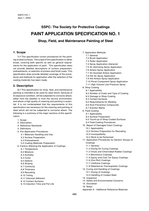
SSPC-PA 1Ap r i l1,2000SSPC: The Society for Protective Coatings PAI NT APPL I CA TI ON SPE CI F I CA TI ON NO. 1 Shop, F iel d, and M aintenance Painting of Steel1. Scop e1.1T h i s s p e c i f i c a t i o n c o v e r s p r o c e d u r e s f o r t h e p a i n t-i n g o f s t e e l s u r f a c e s.T h e s c o p e o f t h i s s p e c i f i c a t i o n i s r a t h e r b r o a d,c o v e r i n g b o t h s p e c i f i c a s we l l a s g e n e r a l r e q u i r e-m e n t s f o r t h e a p p l i c a t i o n o f p a i n t.T h i s s p e c i f i c a t i o n d o e s n o t p r o v i d e d e t a i l e d d e s c r i p t i o n s o f s u r f a c e p r e p a r a t i o n, p r e t r e a t m e n t s,o r s e l e c t i o n o f p r i m e r s a n d f i n i s h c o a t s.T h i s s p e c i f i c a t i o n d o e s p r o v i d e d e t a i l e d c o v e r a g e o f t h e p r o c e-d u r e s a n d m e t h o d s f o r a p p l i c a t i o n a f t e r t h e s e l e c t i o n o f t h e c o a t i n g m a t e r i a l s h a s b e e n m a d e.2. Descrip tion2.1T h i s s p e c i f i c a t i o n f o r s h o p,f i e l d,a n d m a i n t e n a n c e p a i n t i n g i s i n t e n d e d t o b e u s e d f o r s t e e l wh i c h,b e c a u s e o f i t s e x p o s u r e c o n d i t i o n,wi l l b e s u b j e c t e d t o c o r r o s i v e a t t a c k, e i t h e r f r o m t h e we a t h e r o r f r o m t h e s e r v i c e e n v i r o n m e n t, a n d wh e r e a h i g h q u a l i t y o f c l e a n i n g a n d p a i n t i n g i s e s s e n-t i a l.I t i s n o t c o n t e m p l a t e d t h a t t h e r e q u i r e m e n t s o f t h i s s p e c i f i c a t i o n a r e n e c e s s a r y f o r t h e c l e a n i n g a n d p a i n t i n g o f s t e e l wh i c h wi l l n o t b e s u b j e c t e d t o c o r r o s i v e a t t a c k.T h e f o l l o wi n g i s a s u m m a r y o f t h e m a j o r s e c t i o n s o f t h i s s p e c i f i-c a t i o n.1.Sc o p e2.De s c r i p t i o n3.Re f e r e n c e St a n d a r d s4.De f i n i t i o n s5.Pr e-Ap p l i c a t i o n Pr o c e d u r e s5.1M a t e r i a l s Ha n d l i n g a n d Us e5.2Su r f a c e Pr e p a r a t i o n5.3Pr e t r e a t m e n t s5.4 Co a t i n g M a t e r i a l s Pr e p a r a t i o n6.F a c t o r s Af f e c t i n g t h e Ap p l i c a t i o n o f Co a t i n g s6.1T e m p e r a t u r e6.2M o i s t u r e6.3Hu m i d i t y6.4 Co v e r6.5De f e c t s6.6St r i p i n g6.7Co n t i n u i t y6.8 T h i c k n e s s6.9Re c o a t i n g6.10T i n t i n g6.11I n t e r c o a t Ad h e s i o n6.12Co n t a c t Su r f a c e s6.13I n d u c t i o n T i m e a n d Po t L i f e7.Ap p l i c a t i o n M e t h o d s7.1G e n e r a l7.2Br u s h Ap p l i c a t i o n7.3Ro l l e r Ap p l i c a t i o n7.4 Sp r a y Ap p l i c a t i o n(G e n e r a l)7.5Ai r At o m i z i n g Sp r a y Ap p l i c a t i o n7.6Ai r l e s s Sp r a y Ap p l i c a t i o n7.7Ai r-As s i s t e d Ai r l e s s Ap p l i c a t i o n7.8 Ho t Ai r Sp r a y Ap p l i c a t i o n7.9Ho t Ai r l e s s Sp r a y Ap p l i c a t i o n7.10Pl u r a l Co m p o n e n t Sp r a y Ap p l i c a t i o n7.11Hi g h Vo l u m e L o w-Pr e s s u r e Sp r a y8.Sh o p Co a t i n g8.1Ap p l i c a b i l i t y8.2Nu m b e r o f Co a t s a n d T y p e o f Co a t i n g8.3Da m a g e t o Sh o p Co a t i n g8.4 Co n t a c t Su r f a c e s8.5Re q u i r e m e n t s f o r W e l d i n g8.6Ru s t Pr e v e n t i v e Co m p o u n d s8.7Er e c t i o n M a r k s9.F i e l d Co a t i n g9.1Ap p l i c a b i l i t y9.2Su r f a c e Pr e p a r a t i o n9.3T o u c h-u p o f Sh o p Co a t e d Su r f a c e s9.4 F i e l d Co a t i n g Pr o c e d u r e s10.Re p a i r o f Da m a g e d I n t a c t Co a t i n g s10.1Ap p l i c a b i l i t y10.2Su r f a c e Pr e p a r a t i o n f o r Re c o a t i n g10.3I n c o m p a t i b i l i t y10.4 W o r k t o b e Pe r f o r m e d11.Ap p l i c a t i o n Pr o c e d u r e s f o r G e n e r i c G r o u p s o fCo a t i n g s11.1G e n e r a l11.2Dr y i n g O i l Cu r i n g Co a t i n g s11.3Vi n y l s a n d Ch l o r i n a t e d Ru b b e r Co a t i n g s11.4 Bi t u m i n o u s Co a t i n g s11.5Ep o x y a n d Co a l T a r Ep o x y Co a t i n g s11.6Z i n c-Ri c h Co a t i n g s11.7Ur e t h a n e Co a t i n g s11.8 W a t e r b o r n e T h e r m o p l a s t i c Co a t i n g s12.Cu r i n g a n d Ha n d l i n g o f Co a t i n g s12.1Dr y i n g o f Co a t i n g s12.2Ha n d l i n g o f Co a t e d St e e l13.I n s p e c t i o n14.Sa f e t y a n d En v i r o n m e n t a l Co n c e r n s15.Di s c l a i m e r16.No t e sAp p e n d i x A -Ad d i t i o n a l Re f e r e n c e M a t e r i a l s488SSPC-PA 1 April 1, 20003. Reference Standards3.1 The standards referenced in this specification are listed in Sections 3.4 through 3.7 and form a part of this specification.3.2The latest issue, revision, or amendment of the referenced standards in effect on the date of invitation to bid shall govern unless otherwise specified.3.3 If there is a conflict between the requirements of any of the cited reference standards and this specification, the requirements of this specification shall prevail.3.4 SSPC: THE SOCIETY FOR PROTECTIVE COAT-ING S STANDARDS:P A 2Measurement of Dry Coating ThicknessWith Magnetic GagesP A Gu ide 3A Guide to Safety in Paint ApplicationSP 1Solvent Cleaning3.5 AMERICAN SOCIETY FOR TESTING AND MATE-RIALS (ASTM) STANDARDS:D 16T erminology Relating to Paint, V arnish,Lacquer, and Related ProductsD 4285Method for Indicating Oil or Water inCompressed Air3.7 NACE INTERNATIONAL STANDARD:RP0178Fabrication Details, Surface Finishing Re-quirements, and Proper Design Consider-ations for Tanks and Vessels to be Linedfor Immersion Service4. Definitions4.1 SHOP, FIELD AND MAINTENANCE COATING: The application of coatings to steel surfaces whether in the shop or in the field.4.2 PAINT: In the general sense, paint includes prim-ers, enamels, varnishes, emulsions, catalyzed coatings, bituminous coatings, and other organic coatings. Inorganic coatings which are also applied as liquid films are included in this definition. This definition is compatible with most commonly used industry glossaries.4.3 SHOP COATING: The surface preparation and coating of steel surfaces inside a shop or plant before shipment to the site of erection.4.4FIELD COATING: The on-site coating of new or previously coated steel structures before or after erection.4.5MAINTENANCE COATING:The coating of steel structures in service that have been previously coated and require touch-up or recoating.4.6MANUFACTURER’S INSTRUCTIONS AND REC-OMMENDATIONS: These (or similar terms) are used to refer to an equipment supplier’s or coating manufacturer’s latest published or written instructions and recommenda-tions. Verbal recommendations or instructions from an equipment or coating manufacturer are not acceptable unless backed up in writing by the manufacturer’s technical staff.5. Pre-Application Procedu resSee Section 11 for procedures unique to specific generic coatings.5.1 MATERIALS HANDLING AND USE5.1.1 All coating shall be delivered to the shop or jobsite in original, unopened containers with labels intact. Minor damage to containers is acceptable provided the container has not been punctured or the lid seal broken.5.1.2Each container of coating shall be clearly marked or labelled to show coating identification, date of manufac-ture, batch number, and other information as needed to meet regulatory requirements. Each type of coating shall be accompanied by the manufacturer’s Material Safety Data Sheet (MSDS) and product data sheet containing information such as basic chemical composition, weather conditions acceptable for application, and proper storing and mixing.5.1.3 All containers of coating shall remain unopened until required for use. No more containers of coating shall be opened than will be applied that day. The label informa-tion shall be legible and shall be checked at the time of use.5.1.4Coating which has livered, gelled, or otherwise deteriorated during storage shall not be used;however, thixotropic materials which can be stirred to attain normal consistency may be used.5.1.5 The oldest coating of each kind that is in accept-able condition shall be used first. In every case, coating is to be used before its shelf life has expired. Before using a coating which has exceeded its shelf life, the manufacturer shall verify its quality and then certify its use for a given period of time.5.1.6Coatings shall be stored in original unopened containers in weathertight spaces where the temperature is maintained between 40 °F and 100 °F (4 °C and 38 °C) unless otherwise recommended in writing by the manufac-turer. The coating temperature shall be brought to the manufacturer’s written recommended application tempera-ture before use. (See Note 16.1 for more information on coating storage.)5.2 SURFACE PREPARATION5.2.1 The surface shall be cleaned as specified in the procurement documents. In no event shall the surface preparation be less than the paint manufacturer’s recom-mendations for the intended service environment.5.2.2The surface to be coated shall have the specified surface preparation at the time of application of the coat-489SSPC-PA 1 April 1, 2000ing. If the surface is degraded or contaminated subsequent to surface preparation and prior to coating, the surface shall be restored to the specified condition before coating appli-cation (see Note 16.2).5.2.3 In order to control the degradation or contamina-tion of cleaned surfaces, the pretreatments, or, in the ab-sence of a pretreatment, the prime coat shall be applied as soon as possible after the surface has been cleaned and before degradation or contamination has occurred. Suc-ceeding coats shall be applied before contamination of any existing coating occurs.5.2.4Previously applied coating shall be roughened prior to coating whenever necessary for the development of proper intercoat adhesion (see Section6.11).5.2.5 Cleaning and coating shall be scheduled to mini-mize the amount of dust and other contaminants that may fall on newly applied wet coating films. Surfaces not in-tended to be coated shall be suitably protected from the effects of cleaning and coating operations.5.3 PRETREATMENTS5.3.1When specified, the surface shall be pretreated prior to application of the prime coat of coating.5.3.2. The provisions of Sections 5.1 and 5.2 shall also apply to pretreated surfaces and the materials used for this purpose.5.3.3When chemical pretreatments are used, sufficient time shall elapse between pretreatment and application of the prime coat to permit any chemical action to be completed and the surface to dry. Two-component pretreatments shall be applied within the specified interval after mixing. When proprietary pretreatments are used, the instructions of the manufacturer shall be followed.5.3.4Inhibitive water washes used to prevent rusting of cleaned surfaces prior to coating shall not be considered pretreatments. These may be used only if they do not adversely affect the long term performance of the coating and are specifically authorized. Test patches may be used to check adhesion of the coating prior to coating the entire surface.5.4 COATING MATERIALS PREPARATION5.4.1 Single component coatings shall be thoroughly mixed to obtain a uniform composition. For multiple compo-nent coatings, each component shall be thoroughly mixed before combining and further mixing. In all cases, the manufacturer’s written instructions for mixing shall be fol-lowed, and the products shall be checked for complete uniformity.5.4.2 The following are acceptable methods for mixing most coatings:5.4.2.1 Manual (Hand) Mix ing: Most of the vehicle shall be poured off into a clean container. The pigment in the coating shall be lifted from the bottom of the container with a broad, flat paddle, lumps shall be broken up, and the pigment thoroughly mixed with the remaining vehicle. The poured off vehicle shall be returned to the coating with simultaneous stirring, or boxed until the composition is uniform. “Boxing”is the process of mixing coating by pouring from one container to another. The maximum container size for “boxing” shall be five gallons.5.4.2.2 Pow er Mix ing: This will usually give better mixing in a much shorter time than mixing by hand.5.4.3 All pigmented coating shall be strained after mixing except where application equipment is provided with strainers. Strainers shall be of a size to remove only skins and undesirable matter but not to remove the pigment.5.4.4 Where a skin has formed in the container, the skin shall be cut loose from the sides of the container, removed and discarded. If the volume of such skins is visually estimated to be more than 2%of the remaining coating, the coating shall not be used.5.4.5Mixing of solvent-containing coatings in open containers shall be done in a well ventilated area away from sparks or flames.5.4.6 Coating shall not be mixed or kept in suspension by means of an air stream bubbling under the coating surface.5.4.7 Dry pigments which are separately packaged shall be mixed into coatings in such a manner that they are uniformly blended and all particles of the dry powder are wetted by the vehicle.5.4.8 Pastes shall be made into coatings in such a manner that the paste shall be uniformly blended and all lumps and particles broken up to form a homogenous coating.5.4.9 Coating which does not have a limited pot life or does not deteriorate on standing may be mixed at any time before using, but if settling or phase separation has oc-curred it must be remixed immediately before using.5.4.10Coating shall not remain in spray pots, painters’buckets, etc., overnight, but shall be stored in a covered container and remixed before use.5.4.11Catalysts, curing agents, or hardeners which are separately packaged shall be added to the base coating only after the latter has been thoroughly mixed. The proper volume of the catalyst shall then be slowly poured into the required volume of base with constant agitation. Mixing of complete kits is preferred to avoid mixing incorrect ratios of components. Do not pour off the liquid which has separated from the pigment and then add the catalyst to the settled pigment to aid mixing. The mixture shall be used within the pot life specified by the manufacturer. For example, more490SSPC-PA 1 April 1, 2000than 20 minutes and less than eight hours after mixing are the pot life limits for some chemically cured coatings (see Section 6.13). Therefore only enough coating should be catalyzed for prompt use. Most mixed, catalyzed coatings cannot be stored, and unused portions of these shall be placed in proper storage containers for later appropriate disposal. When specified, special continuous mixing equip-ment shall be used according to the manufacturer’s direc-tions.5.4.12 Thinning of the coating shall be done only when necessary for proper application and when it will not result in violation of air pollution control regulations. Coatings to be applied by brush will usually require no thinning. Coatings to be sprayed, if not specifically formulated for spraying, may require thinning when proper adjustment of the spray equip-ment and air pressure does not result in satisfactory coating application. In no case shall more thinner be added than that recommended by the manufacturer’s written instructions.5.4.13The type of thinner shall comply with the manufacturer’s instructions.5.4.14 When the use of thinner is permissible, thinner shall be added slowly to coating during the mixing process. All thinning shall be done under supervision of a knowledge-able person acquainted with the correct amount and type of thinner to be added to the coating and familiar with pertinent regulations relating to solvent emissions. Thinner should be at the same temperature as the coating material. At very low temperatures, thinners can shock sensitive coating materi-als, resulting in gelling.6. Factors Affecting Application of Coat-ingsSee Section 11 for factors unique to specific generic coatings.6.1 TEMPERATURE: The application of a coating sys-tem shall occur only when the air and substrate temperature is within the range indicated by the manufacturer’s written instructions for both application and curing and can be expected to remain in that range. Special coating materials are available that would allow for application below 60°F with or without further adjustment. (See Note 16.3.)6.2 MOISTURE: Coating shall not be applied in rain, wind, snow, fog, or mist, or when the steel surface tempera-ture is less than 5 °F (3 °C) above the dew point. Coating shall not be applied to wet or damp surfaces unless the coating is formulated and certified by the manufacturer for this type of application. Coating shall not be applied on frosted or ice-coated surfaces (see Note 16.4).6.3 HUMIDITY:Because curing of coatings may be adversely affected by humidities that are too low or too high, no coating shall be applied unless the manufacturer’s writ-ten requirements for humidity are met.6.3.1 Some coatings (e.g., some inorganic zinc andpolyurethane coatings) cure by chemically reacting with water, and so require a minimum humidity for complete curing.6.3.2 High humidities may cause moisture to condenseon or react with uncured coating films to cause blushing or other adverse effects.6.4 COVER: When coating must be applied in damp orcold weather, the steel must be coated when the surround-ing air and the steel are heated to a satisfactory tempera-ture. In all such cases, the temperature and moisture conditions of Sections 6.1 and 6.2 must be met. Where cover is required to achieve these conditions, the steel shall remain under cover or be protected until dry or weather conditions permit its exposure.6.5 DEFECTS:Defects in films that are not permitted bythe contract specification shall be corrected in a manner satisfactory to the owner.6.6 STRIPING:If stripe coating is specified in theprocurement documents, all corners, crevices, rivets, bolts, welds, and sharp edges shall be stripe coated with the priming coating before the steel receives its first full prime coat of coating. Such striping shall extend a minimum of one inch (2 cm) from the edge. The stripe coat shall set to touch before the full prime coat is applied. However, the stripe coat shall not be permitted to dry for a period long enough to allow rusting of the unprimed steel. Alternatively, the stripe coat may be applied after a complete prime coat.Stripe coating of edges, corners, rivets, welds, etc., is advantageous in preventing breakdown of coating on such edges in very corrosive surroundings. Striping is an expen-sive operation and may only be justified when it is believed the cost will be compensated for by extra life. To prevent removal of the stripe coat of coating by later application of the prime coat, the striped coating should be allowed to at least set to touch before application of the full prime coat; a longer drying period is advantageous, however. Where it is felt that a long drying period of stripe is necessary, but the precoated steel will deteriorate in the interval, the full prime coat of coating may be applied, allowed to dry, and the stripe coating then applied. Tinting of the striping coating is advis-able to promote contrast (see Section 6.10). Stripe coating is most effective on edges that are rounded by grinding.6.7 CONTINUITY:To the maximum extent practical,each coat shall be applied as a visually continuous film of uniform thickness free of pores. All thin spots or areas missed in the application shall be recoated and permitted to dry before the next coat of coating is applied.6.8 THICKNESS:Unless otherwise specified in theprocurement documents, all dry film thickness determina-tions shall be performed as specified in PA 2, Measurement of Dry Coating Thickness with Magnetic Gages. Coating thickness is usually specified (or implied) as a minimum.Greater thickness that does not detrimentally affect the491SSPC-PA 1 April 1, 2000appearance or service life of the coating is permitted unless otherwise specified.6.8.1 If not otherwise specified, each prime coat shall be within a thickness range of 1.5 mils (38 micrometers) to 2.5 mils (64 micrometers) when dry. Each intermediate and finish coat shall be within a thickness range of 1.0 mils (25 micrometers) to 2.0 mils (51 micrometers). As indicated in Section 11, vinyls, lacquers, emulsions, high-build coatings, and bituminous coatings usually deviate from these thick-nesses.6.8.2In the event the required minimum thickness is not achieved as specified, additional coats shall be applied in accordance with the manufacturer’s instructions until the required thickness is obtained. The inorganic zinc-rich coat-ings shall not be corrected in this manner unless the manufacturer's instructions specifically permit this practice.6.9 RECOATING:Each coating layer shall be in a proper state of cure or dryness before the application of the succeeding coat so that it is not adversely affected by topcoating. Consult the coating manufacturer for the appro-priate time interval before recoating.6.10 TINTING:When successive coats of coating of the same color have been specified, alternate coats of coating shall be tinted, when practical, to produce enough contrast to indicate complete coverage of the surface. Tint-ing shall be performed in such a manner that it will not be necessary to tint the final coat. Field tinting shall be done only with coatings of the same type from the same manufac-turer. When the coating is the color of the steel, the first coat to be applied shall be tinted. The tinting material shall be compatible with the coating and not detrimental to its service life. It is suggested that the coating be tinted by the manu-facturer and appropriately labeled. Single component coat-ings to be blended for tinting shall be thoroughly mixed separately before combining and further mixing. For mul-tiple-components, it is necessary to blend similar compo-nents of the two different colors together before combining and mixing these blends.6.11 INTERCOAT ADHESION:When applying multiple coats of two component thermosetting systems, topcoats shall be applied within the recoat window specified by the manufacturer of the undercoat in order to obtain good intercoat adhesion. If, for any reason, this time period is exceeded, the undercoat surface shall be specially treated as recommended by its manufacturer before topcoating. Such treatments include mild abrasion, solvent treatment, and use of a fog coat.6.12 CONTACT SURFACES: Unless otherwise re-quired by the contract specification, the following practice shall be followed regarding coating of contact surfaces.6.12.1Steel to be embedded, encased or completely enclosed in brick or masonry shall be given at least one coat of coating that is compatible with masonry materials.6.12.2 The areas to be in contact with wood shallreceive the full specified coating system before assembly.6.12.3Surfaces to be in contact only after field erectionshall receive the full-specified coating system before as-sembly.6.12.4 Steel surfaces not in direct bonded contact, butinaccessible after assembly, shall receive the full-specified coating system before assembly.6.12.5Contact surfaces of members to be joined byhigh strength bonds in a friction connection are a special case. Unless specifically authorized to the contrary, they shall be left uncoated and free of oil, grease, and coatings.However, faying surfaces of friction connection may be coated with approved coatings which do not release the coefficient of friction between contact surfaces, in accor-dance with the American Institute of Steel Construction (AISC) and the Research Council on Structural Connections (RCSC).6.13INDUCTION TIME AND POT LIFE: The inductiontime (sometimes called “sweat-in time”) and pot life require-ments of the manufacturer shall be met.7. Application MethodsSee Section 11 for application methods unique to spe-cific generic coatings.7.1 GENERAL:7.1.1 The following methods of application are coveredby this specification: brush, roller, air spray, airless spray, plural component spray, hot spray, or any combination of these methods. Daubers or natural or synthetic wool mitts or other applicators may be used for places of difficult access when no other method is practical. Whichever application method is used, the dry film thickness of each coat shall m e e t t h e r e q u i r e m e n t o f t h e s p e c i f i c a t i o n o r t h e manufacturer’s recommendation, whichever has prece-dence, as agreed upon by owner and contractor. Also see Note 16.5.7.1.2The following methods of application are notcovered by this specification: dipping, flow coating, electro-static spray, and fluidized bed. If application by one of these methods is specified, it shall be done in accordance with the procurement documents or, if none are present, with the manufacturer's recommendations.7.2 BRUSH APPLICATION: Brush application of coat-ing shall be in accordance with the following:7.2.1Brushes shall be of a style and quality that willenable proper application of coating. Round or oval brushes are generally considered most suitable for rivets, bolts, irregular surfaces, and rough or pitted steel. Wide, flat brushes are suitable for large flat areas, but they should not have a width over five inches.492SSPC-PA 1 April 1, 20007.2.2 The brushing shall be done so that a smooth coat as uniform in thickness as possible is obtained.7.2.3Coating shall be worked into all crevices and corners.7.2.4 All runs or sags shall be brushed out. (See 7.3.4.)7.2.5 An attempt shall be made to minimize brush marks and other surface irregularities.7.3 ROLLER APPLICATION: Roller application shall be in accordance with the following:7.3.1Rolling shall be done so that a smooth coat as uniform in thickness as possible is achieved.7.3.2Roller covers shall be selected which do not shed fibers into the paint. Their nap should be appropriate for the particular surface roughness.7.3.3 Roller application may be used on flat or slightly curved surfaces and shall be in accordance with the recom-mendations of the coating manufacturer and roller manufac-turer. Coating rollers shall be of a style and quality that will enable proper application of coating having the continuity and thickness required in Sections 6.7 and 6.8.7.3.4Roller application shall not be used on irregular surfaces such as rivets, bolts, crevices, welds, corners, or edges, unless otherwise specified. When permitted, how-ever, the coating applied by roller on these irregular sur-faces shall be subsequently brushed out to form a continu-ous and unbroken film (see Note 16.6).7.4 SPRAY APPLICATION (GENERAL): All spray ap-plication of coating, whether air spray, airless spray, plural-component spray, hot air spray or hot airless spray, shall be in accordance with the following:7.4.1 The equipment used shall be suitable for the intended purpose, shall be capable of properly atomizing the coating to be applied, and shall be equipped with suitable pressure regulators and gages. The equipment shall be maintained in proper working condition. Spray equipment shall meet the material transfer requirements of the local air pollution or air quality management district.7.4.2Coating ingredients shall be kept uniformly mixed in the spray pots or containers during coating application either by continuous mechanical agitation or by intermittent agitation as frequently as necessary.7.4.3 Spray equipment shall be kept sufficiently clean so that dirt, dried coating, and other foreign materials are not deposited in the coating film. Any solvents left in the equip-ment shall be completely removed before using.7.4.4Coating shall be applied in a uniform layer with overlapping at the edges of the spray pattern. During appli-cation, the gun shall be held perpendicular to the surface and at a distance which will ensure that a wet layer of coating is deposited on the surface. The trigger of the gun should be released at the end of each stroke.7.4.5 All runs and sags shall be brushed out immedi-ately, and if not, the coating shall be removed and the surface repainted. The wet film may be removed or allowed to dry and removed by sanding after curing.7.4.6 Cracks, crevices, blind areas of all rivets andbolts, and all other inaccessible areas shall be coated by brush or daubers.7.4.7 Particular care shall be observed with respect totype of thinner, amount of thinner, coating temperature, and operating techniques in order to avoid deposition of coating which is too viscous, too dry, or too thin. It may be necessary to use an approved different coating material or other equipment to resolve these problems.7.4.8Coatings formulated for application to hot sur-faces may not be suitable for application to surfaces below the designed temperature. Conversely, coatings formu-lated for application at ambient or low temperatures may not be suitable for application to hot surfaces. Thus, coatings shall not be applied outside the manufacturer’s recom-mended temperature range without the written approval of the manufacturer and the owner.7.5 AIR ATOMIZ ING SPRAY APPLICATION:Com-pressed air atomizing spray application of coating shall be in accordance with all the provisions of Section 7.4 and in addition shall comply with the following:7.5.1 The air caps, nozzles, and needles shall be thoserecommended by the manufacturers of the material being sprayed and the manufacturers of the equipment being used.7.5.2 Traps or separators shall be provided to removeany oil or condensed water from the air. The traps or separators must be of adequate size and must be bled continuously or drained periodically during operations. The air from the spray gun impinging against a clean surface shall show no condensed water or oil. ASTM D 4285 provides a test procedure for indicating the presence of oil or water in compressed air.7.5.3The pressure on the material in the pot and of theair at the gun shall be adjusted for optimum spraying effec-tiveness. The pressure on the material in the pot shall be adjusted when necessary for changes in elevation of the gun with respect to the elevation of the pot. The atomizing air pressure at the gun shall be high enough to properly atomize the coating, but not so high as to cause excessive fogging of coating, excessive evaporation of solvent or loss by overspray.7.6 AIRLESS SPRAY APPLICATION: Airless or highpressure spray application of coating shall be in accordance with all of the provisions of Section 7.4 and in addition shall comply with the following:7.6.1 Fluid tips shall be of proper orifice size and fanangle, and the fluid control gun of proper construction, as recommended by the manufacturer of the material being493。
钢结构工程油漆施工工艺(中英文双版)
CONTENT 目录1. Scope 前言........................................................................................................................................ - 2 -2. General概述..................................................................................................................................... - 3 -3. Standards, References, Definitions and Abbreviations 标准和参考文献................................. - 3 -4. Coating System油漆配套............................................................................................................... - 5 -5. General painting works sequence通用喷涂施工流程............................................................... - 16 -6. General inspecting equipments and tools 常规检测设备和工具............................................. - 17 -7. Surface Preparation表面处理....................................................................................................... - 18 -8. Application of coating system油漆施工.................................................................................... - 23 -9 .Repair and Touch up涂层损伤的修补 ......................................................................................... - 45 -10 .QC & QA质量控制和质量保证 ................................................................................................... - 47 -11 .Handling, Storage and Delivery搬运, 存放及发运.................................................................. - 50 -12. HSE 健康、安全和环境............................................................................................................... - 50 -13. Revision 建议的修正 ................................................................................................................... - 52 -Painting Procedure 油漆施工工艺1. Scope 前言This Painting Technology Specification covers surface preparation and painting activities and is prepared with reference to the Painting Specification for the BYC Phase II Project. This document is organized on basis of International Protective Coatings Products Data Sheets of ANIP. It is composed of additional regulations and the detail descriptions in the above documents mentioned, and therefore is not to be the substitute of them. The specification is prepared with the reference of the Project Contract Specification.本技术工艺是针对扬子-巴斯夫二期项目的油漆施工技术规范的表面处理及涂装的说明。
t∕cecs 714-2020 古建筑木结构检测技术标准
t∕cecs 714-2020 古建筑木结构检测技术标准钢结构现场检测技术标准(T/CECS XXX-2021)和中国古建筑现场无损检测技术(t∕cecs714-2020)分别为古建筑和钢结构现场的检测提供了详细的方法和规范。
在古建筑木结构检测技术标准中,针对木结构的特点,制定了材料性能检测、结构稳定性检测、虫害与腐朽检测、裂缝与变形检测、涂料与彩画检测等方面的技术要求。
钢结构现场检测技术标准(T/CECS XXX-2021)则分为11章和5个附录,主要包括:总则、术语和符号、基本规定、钢材力学性能检测与化学成分分析、焊缝连接质量检测、紧固件连接质量检测、尺寸与变形检测、外观质量与损伤检测、涂装质量检测、轻钢围护结构质量检测、结构构件性能检验等。
在古建筑木结构检测技术标准(t∕cecs714-2020)中,材料性能检测是关键环节。
主要包括木材物理性能检测(如含水率、密度等)和木材力学性能检测(如抗弯强度、抗弯弹性模量等)。
这些检测有助于了解木材的现状,为后续维修和保护提供依据。
结构稳定性检测是古建筑木结构检测的重要内容。
通过对古建筑木结构的构件、连接件、支撑系统等进行检查,确保结构的安全和稳定。
同时,检测虫害与腐朽情况,及时发现并处理问题,防止病虫害的蔓延与发展。
裂缝与变形检测旨在了解古建筑木结构在自然环境和使用过程中产生的裂缝和变形情况,分析原因,提出相应的处理措施。
涂料与彩画检测则针对古建筑木结构表面的涂装层和彩画进行评估,为其维修和保护提供参考。
钢结构现场检测技术标准(T/CECS XXX-2021)同样注重检测方法的实际操作。
在现场检测过程中,要对钢材力学性能、焊缝连接质量、紧固件连接质量等进行详细检查,以确保钢结构的安全和稳定。
此外,尺寸与变形检测、外观质量与损伤检测、涂装质量检测等也是关键环节,有助于发现潜在问题,及时进行修复和维护。
总之,古建筑木结构检测技术标准(t∕cecs714-2020)和钢结构现场检测技术标准(T/CECS XXX-2021)为现场检测提供了详细的方法和规范,确保了古建筑和钢结构结构的安全与稳定,为我国建筑行业的健康发展提供了有力保障。
钢结构喷漆要求范例

PAINTING SPECIFICATION
Comes standard painting
Preparations of the superficies 表面处理 Grinding or Sand blasting; 打磨或喷砂 Pickling and cleaning; 酸洗和清洁
Primary painting 底漆 It is done within max 12 hours after the described treating 喷漆要在表面处理 12 小时以内进行 It is composed of epoxy resin with a high zinc rated (90% dry) in order to get a good protection against the corrosion; 由环氧树脂(含锌 90%左右)调成高浓的油漆,以便能有更好的防腐蚀保护。 Coat thickness: min. 30µm; 涂层厚度最少 30µm。 Colour: Grey 颜色:灰
Final painting 面漆 Polyurethane painting; 聚亚安酯油漆 Coat thickness: min. 50µm 涂层厚度:最少 50µm Colour: RAL 9001white 颜色:乳白(国际颜色代号 RAL 9001)ce: 24 hours at 100°C (white); 耐热:100°C,24 小时 Adhesion: DIN 53151 grating – 100% G.T.O. 划格试验(满足德国标准 DIN53151,100%G.T.O) Total coat thickness: min. 80µm 总的涂层厚度:最少 80µm
钢结构检验资料中英文
《low-alloy high-strength structural steel》(GB/T1591-94) 《低合金高强度结构钢》(GB/T1591-94)《Carbon Structural Steel》(GB/T700-1988)《碳素结构钢》(GB/T700-1988)< Carbon Steel Weld Rods>(GB/T5117-1995)《低合金钢焊条》(GB/T5117-1995)<Steel Wire used for Weld>(GB/T14957-1994) 《熔化焊用钢丝Steel Wires for melt weld》(GB/T14957JGJ81-2002《建筑钢结构焊接技术规程》<<Achitecture steel structure welding rule>>《钢结构焊缝外形尺寸》(GB10854-89)<<Steel structure welded seam physical dimension>>( GB10854-89)《钢结构工程施工质量验收规范》(GB50205-2001)<<Steel structure engineering construction quality acceptance rule>> GB50205-2001<< Steel structure high strength bolt connection design, construction and acceptance rule>> (JGJ82-91). <<钢结构高强度螺栓连接的设计.施工及验收规程>>GB8923<<涂装前钢材表面锈蚀等级和除锈等级>>Steel surface rusting grade and de-rusting grade before coating完工面漆:色泽均匀,无流挂、无漆雾、无污染。
- 1、下载文档前请自行甄别文档内容的完整性,平台不提供额外的编辑、内容补充、找答案等附加服务。
- 2、"仅部分预览"的文档,不可在线预览部分如存在完整性等问题,可反馈申请退款(可完整预览的文档不适用该条件!)。
- 3、如文档侵犯您的权益,请联系客服反馈,我们会尽快为您处理(人工客服工作时间:9:00-18:30)。
SECTION 714PAINTING STRUCTURAL STEEL714.1 DESCRIPTIONPrepare the structural steel surfaces, and paint the structural steel as shown in the Contract Documents. Provide environmental protection as necessary.BID ITEMS UNITSBridge Painting (*) Lump SumSumLumpProtectionEnvironmentalPower Wash Lump Sum*Type of Paint System714.2 MATERIALSProvide paint materials that comply with DIVISION 1800.Formulate the inorganic zinc or organic zinc coating to provide a tint which distinctly contrasts with blast cleaned metal surfaces and the finish coat.714.3 CONSTRUCTION REQUIREMENTSa. General Requirements for Painting Structural Steel.(1) Surface Preparation Before Applying The Prime Coat. Blast all surfaces with abrasives to produce a height of profile of 1 to 3 mils.Clean structural steel surfaces to meet the Society for Protective Coatings’ (SSPC) specification SSPC-SP10, Near-White Blast Cleaning. Limit staining to a maximum of 5% of each square inch of surface area.If specified (such as for unpainted surfaces of weathering steel or when repainting existing bridges in kind), clean structural steel surfaces to meet SSPC-SP6, Commercial Blast Cleaning, except wet blasting will not be permitted. Staining is limited to a maximum of 33% of each square inch of surface area. If the original surface is pitted, slight residues of rust and paint may be left in the bottom of pits.Staining may consist of slight shadows, slight streaks or minor discoloration caused by stains of rust, stains of mill scale or stains of previously applied paint. When viewed without magnification, the blast cleaned surface shall be free of visible oil, grease, dust, dirt, mill scale, rust, coating, oxides, corrosion products and other foreign matter.Remove all machine cutting oil by cleaning machined surfaces (ANSI 125 micro-inch or smoother). Carefully mask the machined surfaces before blast cleaning the remaining surfaces of the member.After blast cleaning, remove any trace of blast products. Take care to remove abrasives from pockets and corners.Give the blast cleaned surfaces a prime coat of paint within 12 hours of cleaning. Re-clean the blast cleaned surfaces if rust tinge appears before the prime coat is applied.Conditions.Check the air temperature, the steel temperature and the dew point before painting Weather(2)begins each day, and after each suspension of painting due to weather or temperature, if painting is to resume. Do not apply paint if the ambient air temperature is below 40°F, when the air is misty, when the steel temperature is 5º or less above the dew point, or if the Engineer determines conditions are unsatisfactory for painting. Do not apply paint on damp or frosted surfaces. Stop paint application if the Engineer determines the air temperature is so high that the spray dries before reaching the surface, resulting in a dry, powdery coating.(3) Mixing and Thinning Paint.Thoroughly mix the paint and keep the pigment in suspension. Strain the mixed paint when recommended by the manufacturer.If multi-component inorganic zinc primer is used, follow the manufacturer’s instructions regarding the amount and manner of adding the zinc dust to the liquid portion. Strain the mixed paint through a metal screen having a mesh recommended by the manufacturer. Mix multi-component inorganic zinc paint fresh each day and do not use it past the pot life time stated in the manufacturer’s literature.The Engineer will permit paint thinning if required for proper application, but only as recommended by the manufacturer. If thinner is used, add it to the paint during the mixing process. Do not add additional thinner after the paint is thinned to the proper consistency.Use thinner recommended by the manufacturer for inorganic zinc paints. Inorganic zinc paint should not require heating in cool weather, but is permitted provided care is taken that the paint is protected from all moisture.(4) Application of Paint. Apply the paint according to the manufacturer’s instructions. Provide the Field Engineer with a printed copy of the paint manufacturer’s application instructions.Apply the paint using either a conventional or an airless sprayer. Spray from a continuously agitated pot.Apply uniform coatings in tight contact with the metal. Work the coating into all corners and crevices. Apply a coating that is free of all defects.Allow ample time for each paint coating to dry. Do not apply the next coat of paint until the previous coat is inspected by the Engineer and found dry and hard throughout the entire film thickness.Remove and replace defective or unauthorized paint. Prepare the surfaces for repainting and repaint the areas according to the requirements for painting structural steel.When the finish coat is complete, stencil (in black paint) the date the bridge was painted and the code representing the type of paint system used on the bridge. Stencil the legend on the right side of the outside face of the far right stringer near each end of the bridge. Use capital letters, 2 to 3 inches in height. The date stencil shall contain the word "PAINTED" and show the month and the year that the painting was completed. Make the paint system code selection from the following list:Zinc/AcrylicIZ/AInorganicZinc/Polyurethane IZ/PInorganicOZ/AOrganicZinc/AcrylicZinc/Polyurethane OZ/POrganic(5) Staging and Scaffolding. Use adequate staging and scaffolding while painting the structural steel. Do not climb or work on the finished painted members. Provide the Engineer with safe means (such as scaffolding, snoopers or cherry pickers) to inspect any portion of the structure during the cleaning and painting operations.(6) Protection of Pedestrians and Property. When painting on the project site, protect all pedestrians, vehicles (on or underneath the bridge), adjoining property along the right-of-way, pipes or ducts owned by utility companies, and portions of the bridge superstructure and substructure against damage or disfigurement from paint material. The Contractor is responsible for repairing any damage resulting from the painting operations.(7) Maintaining Traffic on Existing Bridges. Provide traffic control as shown in Contract Documents and SECTION 805. Unless traffic is detoured, maintain traffic on the existing bridge at all times during the work of cleaning and painting. At the option of the Contractor when work is being performed, ½ of the roadway on that span may be closed to traffic, with one way traffic being maintained over the other half of the roadway. At all other times when work is not being performed, keep the entire bridge roadway open to traffic.b. Shop Painting Structural Steel (Non-Weathering). The application of the prime coat in the shop must comply with the general requirements for painting structural steel, with these additions and exceptions: Unless shown otherwise in the Contract Documents, apply 1 coat of inorganic zinc primer to the structural steel in the shop. Mask machined surfaces prior to painting. Use primer that is tinted to contrasts (in color) with the blast-cleaned steel and with the finish coat of paint.Apply 2 primer coats (not less than 6 mils total thickness) to surfaces that are not in contact with the concrete, but that will be inaccessible after assembly or erection. Apply the second coat between 4 and 24 hours after application of the first coat.Except where otherwise indicated, coat all blast cleaned surfaces of the structural steel, including contact surfaces of high strength bolt connections and areas in contact with concrete. The dry film thickness of the prime coat shall be 3 to 6 mils on flat areas. More thickness is allowed in fillet areas if there is no evidence of mud cracking, and if the coating is tight. The dry film thickness is measured from the peaks of the blast profile to the surface of the paint.For contact surfaces of high strength bolted connections, the dry film thickness shall be 1.5 to 3 mils. Both sides of steel plates that have holes for high strength fasteners are considered contact surfaces because they come into contact with other steel plates, nuts, washers or fastener heads.Apply 1.5 mils dry film thickness prime coat to top flanges of structural steel members that will have welded stud shear connectors applied in the field. Do not apply the prime coat to surfaces within 6 inches of fieldwelded connections. Coat unpainted surfaces near field welded connections with a rust preventive coating approved by the Engineer. The temporary coating must be easily removed with mineral spirits prior to field welding.After the non-machined surfaces of structural steel are prime coated, remove the masking from the machined surfaces and apply a prequalified coating for use on machined surfaces approximately 3 mils thick.If the dry film thickness of the prime coat is 2 to 3 mils, and less than 24 hours old, either blast clean the deficient area to bare metal and repaint, or apply additional primer. If additional inorganic zinc primer is applied, thin the primer 1:1 with a solvent recommended by the manufacturer of the paint.If the dry film thickness of the prime coat is 2 to 3 mils thick and more than 24 hours old, or if the dry film thickness is less than 2 mils, blast clean the deficient area to bare metal and repaint. Remove excessive film thickness or dry spray.Give the inorganic zinc prime coat a thorough single spray of clean water between 2 and 48 hours after application of the inorganic zinc prime coat, when recommended by the manufacturer.Before the structural steel is shipped to the project site, blast clean to bare metal and repaint defective or damaged areas. Overlap the new prime coat onto the existing prime coat a minimum of 1 inch.Shop painted structural items, except matchmarked girders and beams, that will receive a field coat of paint must have an identification mark painted on their surface, or they may be tagged with a weatherproof tag.c. Field Painting New Structural Steel (Non-Weathering).(1) Prime Coat. Apply a prime coat to the field connections, field welds, nuts, bolts and washers. Re-coat all damaged or defective areas of the shop-applied prime coat. Apply the prime coat in the field complying with the general requirements painting structural steel, with these additions and exceptions:Overlap the shop coat by applying the field-applied prime coat a minimum of 1 inch beyond any surface preparation.If the surface prepared for painting or re-coating is 1 square yard or less, apply organic zinc primer. Use organic zinc primer on bolts, nuts, washers and edges of bolted splice plates.If the surface prepared for painting or re-coating is greater than 1 square yard, blast clean the entire flange or web of the area to be painted or re-coated, and apply inorganic zinc primer. Between 24 and 48 hours after the inorganic zinc primer is applied in the field, apply a coat of organic zinc primer (by brush or spray according to subsection 714.3b.) where the new inorganic zinc prime coat meets or overlaps the shop applied inorganic zinc prime coat.If welded stud shear connectors are applied in the field, blast clean the top of the top flange to SSPC-SP6, Commercial Blast Cleaning. After the welded stud shear connectors are applied, blast clean the top flange and welded stud shear connectors to meet SSPC-SP6, Commercial Blast Cleaning. Thoroughly blast clean the welds. Apply organic zinc primer to the top flange and welded stud shear connectors. The top 1 inch of the welded stud shear connectors (including the underside of the stud head) need not receive a full coat of primer.(2) Finish coat. Protect the primed structural steel from contamination during transport, storage and erection. Do not walk on the primed structural steel. If the primed structural steel is soiled, use water or light blast cleaning to remove the contamination before applying the finish coat of paint.The application of the finish coat in the field shall comply with the general requirements for painting structural steel, with these additions and exceptions:Unless otherwise noted in the Contract Documents, either apply an acrylic or a polyurethane finish coat after the primed structural steel is erected. Apply 1 coat with a dry film thickness of 3 to 6 mils on flat areas. A thickness in excess of 6 mils is allowed in fillet areas if there is no evidence of mud cracking, and if the coating is tight. If bubbles form, allow them to collapse and apply approximately 1 mil of the finish coat to the area where the bubbling occurred.d. Shop Painting New Weathering Steel. Apply the shop painting of new weathering steel complying with the general requirements for painting structural steel and the shop painting of non-weathering structural steel, with these additions and exceptions:Blast clean all surfaces of the weathering steel, including all contact surfaces of bolted connections, to meet SSPC-SP6, Commercial Blast Cleaning.For weathering steel surfaces that require painting, blast clean to meet SSPC-SP10, Near-White Blast Cleaning.Surfaces that require paint include:•girder ends that are embedded in the abutment - the entire embedded portion of the girder, including diaphragms, plus an additional distance of 2 inches;•the top (and sides, if in contact with concrete) of the top flanges, including shear studs. Note: for welded stud shear connectors applied in the field, the top of the top flange does not require a shopprime coat;•all surfaces of top flange top splice plates;•all surfaces of fill plates less than ¼ inch thick. Note: Fill plates need not be weathering steel. Paint fill plates of non-weathering steel, regardless of thickness;•all structural steel surfaces (not included above) within a distance of 2 times the depth of the girder (2D) on either side of an expansion joint. (Note: A nearby stiffener is a convenient location to stoppainting.); and•the exterior girders according to FIGURE 714-1, if drainage is allowed over the side of the deck on a plate girder bridge, and the entire length of the exterior girder is to be painted. Note: If drainage isallowed over the side of the deck on a rolled beam bridge, painting of the exterior beam, except topflange, is not required.e. Field Painting New Weathering Steel. Apply a finish coat to all primed structural steel surfaces still exposed after the placement of superstructure concrete. The surface preparation of the top surface of the top flange (field applied welded stud shear connectors), and the application of the prime coat (including the top of the top flange after welded shear stud connectors have been applied in the field) and the finish coat in the field shall comply with the general requirements for painting structural steel and the field painting of new, non-weathering structural steel, with these additions and exceptions:Unless noted otherwise in the Contract Documents, use a waterborne acrylic, brown finish coat color equivalent to Federal Standard No. 595a, Color No. 30045 (Carboline No. 2248).If drainage is allowed over the side of the deck on a plate girder bridge, and the entire length of the exterior girder is to be painted, apply a finish coat to the exterior girders according to FIGURE 714-1.Unless shown otherwise in the Contract Documents, blast clean the entire exterior facia of the unpainted exterior girders after erection to meet SSPC-SP6, Commercial Blast Cleaning.FIGURE 714-1WEATHERING STEELf. Painting Galvanized Steel. Follow ASTM D 6386 to prepare galvanized surfaces that are to be painted, then apply a primer tiecoat prior to application of the topcoat. Use a tiecoat that is compatible with the topcoat and approved by the Engineer. Follow the manufacturer’s recommendations for application, including dry film thickness and cure time of the primer tiecoat.g. Repainting Steel Bridges - Change Paint System. Repaint the steel bridges. Comply with the general requirements for painting structural steel, with these additions and exceptions:Remove the existing paint system and repaint the bridge with a paint system of organic zinc or inorganic zinc prime coat and acrylic or polyurethane finish coat.Clean and prepare the steel surfaces, including iron or steel casings and metal railings previously painted that are accessible for field painting. Do not paint tops of expansion guard plates, bars or angles across the roadway at joints between adjacent spans on which vehicular traffic comes in direct contact, and pipes or ducts owned by utility companies.If lower chords, braces of truss spans or other members are separated by tie plates or fills, clean the spaces between backs of angles or channels (equal to the thickness of the tie plates or fills) of all rust and loose paint. Tight paint found between splice plates, beneath rivet heads and in other such narrow openings may be left intact. Take special care to remove the rust often found along the edges of the top flanges of I-beams at their line of contact with a concrete deck.Apply the type of prime coat specified in the Contract Documents with 3 to 6 mils dry film thickness of the prime coat on flat areas. More thickness will be allowed in fillet areas if there is no evidence of mud cracking, and if the coating is tight.After the prime coat is dry, give the inorganic zinc prime coat a thorough spray of clean water a minimum of 24 hours before the finish coat is applied. Organic zinc paint does not require a water spray.Spray painting may be waived in those places where it is not possible to blast clean. Clean these areas by hand as well as possible, and apply a heavy coat of organic zinc primer with a brush or dauber.Apply 1 finish coat with 3 to 6 mills dry film thickness on flat areas. A thickness in excess of 6 mils is allowed in fillet areas if there is no evidence of mud cracking, and if the coating is tight. If bubbles form, allow them to collapse and apply an approximate 1 mil of the finish coat to the area where the bubbling occurred.h. Repainting Steel Bridges - Painting In Kind (Bridges with either organic zinc or inorganic zinc prime coat and acrylic or polyurethane finish coat paint systems). Repaint the steel bridges. Comply with the general requirements for painting structural steel, with these additions and exceptions:Prepare the metal surfaces and repaint the bridge with the same paint system as existing.Clean and prepare the steel surfaces, including iron or steel casings and metal railings previously painted that are accessible for field painting. Do not paint tops of expansion guard plates, bars or angles across the roadway at joints between adjacent spans on which vehicular traffic comes in direct contact, and pipes or ducts owned by utility companies.If lower chords, braces of truss spans or other members are separated by tie plates or fills, clean the spaces between backs of angles or channels (equal to the thickness of the tie plates or fills) of all rust and loose paint. Tight paint found between splice plates, beneath rivet heads and in other such narrow openings may be left intact. Take special care to remove the rust often found along the edges of the top flanges of I-beams at their line of contact with a concrete deck.Blast clean the steel surfaces to remove any defective coating. Hand clean widely spaced damaged spots (3/16 inch or less in diameter) on an otherwise tight existing coating. Remove oil and grease using a non-flammable solvent approved by the Engineer.Clean areas according to SSPC-SP6, Commercial Blast Cleaning to produce a height of profile of 1 to 3 mils.Apply 1 coat of organic zinc (minimum dry film thickness of 3 mils) to bare metal. Cover the bare metal and overlap the existing finish coat by 1 inch.Spray painting may be waived in those places where it is not possible to blast clean. Clean these areas by hand as well as possible, and apply a heavy coat of organic zinc primer with a brush or dauber.Use the type of finish coat specified in the Contract Documents. Apply 1 finish coat with 3 to 6 mils dry film thickness on flat areas. A thickness in excess of 6 mils is allowed in fillet areas if there is no evidence of mud cracking, and if the coating is tight. If bubbles form, allow them to collapse and apply an approximate 1 mil of the finish coat to the area where the bubbling occurred.714.4 ENVIRONMENTAL PROTECTION (Existing Paint Systems)Provide environmental protection on a structure whether partially or completely removing an existing paint system. The removal of existing lead-based paint may result in creation of waste subject to hazardous waste regulations.a. Structure Classification. The bridge classification will be included in the Contract Documents, prior to letting.For the purpose of this specification, bridges are classified as:(1) Class A: A bridge in which any part is within 300 feet of:• a residence, a school, a public use area, a commercial/industrial property, agricultural buildings;•or a protected natural area property.(2) Class B: Any bridge that is not Class A.b. Health and Environmental Sampling.(1) The Environmental Services Section (ESS) of the Bureau of Design will conduct a bridge Site Review and Field Survey (SRFS) to document the details of the project and the environmental concerns in the vicinity.(2) Soil samples will be collected by the ESS prior to and at the conclusion of paint removal operations. While conducting the SRFS, soil samples will be collected within KDOT right-of-way from a minimum of 1 test site 10 to 100 feet away from the structure in each of 4 directions. The specific location of each site will be documented. Each test site shall consist of a 1 square foot area. A composite sample will be obtained by collecting soil ¾ inch in diameter and ½ inch in depth at the center of the square and at each of the 4 corners.At the conclusion of the project, soil samples will be collected by the ESS in the same manner at a 1 square foot area within a radius of 5 feet of the original sample location. The pre-job and post-job samples will be analyzed for total lead at a Kansas Department of Health and Environment (KDHE) certified laboratory.(3) The air sampling equipment shall be provided by the Contractor and will remain the property of the Contractor. Collect air samples, unless stated otherwise in the Contract Documents, on all Class A bridges. Collect the samples following the procedures specified in the Code of Federal Regulations (CFR), 40 CFR 58, Appendix G and the quality assurance procedures as specified in 40 CFR 58, Appendix B and 40 CFR 58.20. Employ high volume air samplers to assess the effects of blasting operations on ambient air quality outside the containment structure. Collect air samples each day paint is blasted from the structure. Place the air samplers on KDOT right-of-way in the upwind and downwind position to the prevailing wind at locations expected to experience maximum impact. Locations for air sampling will be approved by the Engineer. Remove and replace the sample filters each day. Store the used filters in air-tight bags, properly identified with date, sample location and KDOT project number.Submit the air sample filters to a KDHE certified laboratory a minimum of once every 5 working days, where they will be analyzed for total lead. Lead concentrations in ambient air must be in compliance with 40 CFR 50, which allows a maximum of 0.05 mil/cubic yard (See Guide 6, Section 5.5.4). The laboratory analyses must be accelerated in order to have analytical results to the Engineer within 5 working days of the original transmittal to the laboratory. Identify the analytical results by the date of collection, type and location of sample, and KDOT project number.If ambient air concentrations exceed regulatory limits, halt blasting operations until containment design controls have been implemented to reduce emissions to a satisfactory level.(4) Collect surface water samples on all bridges located over any perennial stream, river or body of water. Sediment samples may also be required, at the discretion of the Engineer, where stream flow is extremely low, where containment has obviously failed or when paint removal operations exceed 30 calendar days. At the direction of the Engineer, a minimum of 1 sample shall be collected upgradient of the structure and 1 in the down gradient position of the structure during blasting operations. The samples will be representative of the project’s potential impact to the water body and will be collected in the presence of the Engineer. If visible waste or paint chips are observed on the surface of the waterway, halt blasting operations until the containment has been modified to eliminate debris contact with the water surface. This determination will be made by the Engineer. Identify water samples by date, type and location of sample, and KDOT project number. Submit the water samples to a KDHE certified Laboratory for the analysis of total lead within 1 week from the time of collection. Submit the analytical results to the Engineer upon receipt from the laboratory. Identify the analytical results by date of collection, type of sample, Chain of Custody forms, and KDOT project number.(5) Failure to submit analytical data for air and water samples on a timely basis as described above may result in work on the project being suspended by the Engineer until submittals are in compliance. Temporary suspension of work on the project due to non-compliance by the Contractor will not alter or waive the charging of working days for the project.(6) Submit all documentation relative to air and water sample collection and analyses to the ESS within 30 days of completion of the paint removal process. If documentation is not submitted, the Engineer may stop work on the project until such documentation has been received by the Engineer and ESS.c. Notifications and Record Keeping. The ESS will submit a SRFS report to the Bureau of Waste Management (BWM), KDHE, Forbes Field, Topeka, Kansas 66620-0001 a maximum of 60 days before beginning work on the bridges. At the same time, a copy will also be provided to the Bridge Management Section and theappropriate KDOT District Office. The District Office will provide a copy of the Site Review and Field Survey report to the Contractor.At the conclusion of the blasting operations, the ESS will submit a report to the BWM, which includes the results of all air, soil, and surface water samples obtained during the project. A copy of this report will also be provided to the appropriate District Office. The Contractor may receive a copy of this report upon request to the Engineer or ESS.d. Lead Base Paint Removal. The Contractor engaged in lead base paint removal operations must carry a pollution liability (access liability) policy with a minimum coverage of $1,000,000. Maintain this policy in force until the Secretary releases the Contractor from all obligations under the contract. The insurance contract must cover claims for such length of time as said claims are permitted by law. Provide a copy of this insurance certificate to the Engineer prior to beginning lead base paint removal operations.Use best industry practices to protect the environment, persons and adjacent property from contamination due to blasting of the existing structure. When "Power Wash" is shown as a bid item, clean the existing steel before initiating the blasting operations. Use a power washer with pressure in the range of 700 to 1000 pounds per square inch to clean the structure, at a maximum rate of 4 gallons per minute, using potable water. Comply with all applicable regulations contained in K.A.R. 28-16-28 (b) through (f) for protection of water quality, K.A.R. 28-29-1 through 28-29-27 for disposal of solid waste and K.A.R. 28-31-1 through 28-31-14 for disposal of hazardous waste. In addition, comply with all applicable Occupational Safety and Health Administration standards including those found in 29 CFR 1910.1025 covering the occupational exposure to lead and 29 CFR 1926.62 outlining the requirements for the removal of lead-based paint from bridge repair and rehabilitation activities.Contain paint chips, corrosion residues and spent abrasives, referred to as waste materials, resulting from blasting and other cleaning operations. The containment requirements are covered in subsection 714.4e. Use special containment methods or removal procedures over power lines, communication lines, railways or roadways not closed to traffic. Obtain the permits and permission from the line owner on the containment methods and removal procedures. The proposed containment method or removal procedures must be sealed by a licensed Professional Engineer, and submitted to the Engineer before commencing paint removal operations.Clearing of the work area for containment purposes is the responsibility of the Contractor. Clearing may not extend beyond right-of-way. Burning on the right-of-way is prohibited. The area to be cleared and the clearing method must be approved by the Engineer before starting the clearing operation. Provide locations, approved by the Engineer, and dispose of all the debris at said locations.e. Removal and Containment Requirements.(1) Class A Bridges. On all Class A bridges, provide a KDHE certified Lead Abatement Supervisor for oversight of all paint removal, storage and disposal operation. These operations shall adhere to work practices established in K.A.R. 28-72-18(g) and K.A.R. 28-72-18d(a). The Lead Abatement Supervisor must have available at the job-site a telephone number for the nearest Local Emergency Planning Commission (LEPC), or if none can be found within a 50 mile radius, the nearest Haz-Mat Response Contractor.Dry abrasive blasting or any other approved method which meets the paint specification may be used to remove the lead paint from the bridge. Use the containment methods shown below to maximize pollution control.(a) Power Tools: Use containment unless the power tools are vacuum equipped and all parts of thevacuum equipment are in a condition that prevents emissions of waste material. This determinationwill be made by the Engineer.(b) Dry Abrasive Blasting: Use 100% air impenetrable walls with rigid or flexible framing, fullysealed joints, airlock or resealable entryways, and negative air achieved by forced or natural air flow(verified by instrument or visual monitoring) and exhaust air filtration (See SSPC – Guide 6,Paragraph 4.2.2.1).Design the containment to withstand the effects of negative air pressure equal to the combined volume of all blast nozzles inside the enclosure plus 4 air changes of the enclosure per hour. Themethod of attaching and the effects of dead load caused by the installation of the enclosure to thebridge shall be sealed by a licensed Professional Engineer. Provide a copy of such plans to theEngineer for approval before commencing paint removal operations.Recyclable or non-recyclable abrasive may be used. Use recyclable abrasives with a classifier system rated to remove a minimum of 98% of the non-abrasive material, and free of oilsubstances.。