25662927-0制图—2
ASTM E562-02Standard Test Method for Determining Volume Fraction by Systematic Manual Point Count1
Designation:E562–02Standard Test Method forDetermining Volume Fraction by Systematic Manual Point Count1This standard is issued under thefixed designation E562;the number immediately following the designation indicates the year of original adoption or,in the case of revision,the year of last revision.A number in parentheses indicates the year of last reapproval.A superscript epsilon(e)indicates an editorial change since the last revision or reapproval.INTRODUCTIONThis test method may be used to determine the volume fraction of constituents in an opaque specimen using a polished,planar cross section by the manual point count procedure.1.Scope1.1This test method describes a systematic manual point counting procedure for statistically estimating the volume fraction of an identifiable constituent or phase from sections through the microstructure by means of a point grid.1.2The use of automatic image analysis to determine the volume fraction of constituents is described in Practice E1245.1.3This standard does not purport to address all of the safety concerns,if any,associated with its use.It is the responsibility of the user of this standard to establish appro-priate safety and health practices and determine the applica-bility of regulatory limitations prior to use.2.Referenced Documents2.1ASTM Standards:E3Guide for Preparation of Metallographic Specimens2 E7Terminology Relating to Metallography2E407Practice for Microetching Metals and Alloys2E691Practice for Conducting an Interlaboratory Study to Determine the Precision of a Test Method3E1245Practice for Determining the Inclusion or Second Phase Constituent Content of Metals by Automatic Image Analysis23.Terminology3.1Definitions—For definitions of terms used in this prac-tice,see Terminology E7.3.2Definitions of Terms Specific to This Standard:3.2.1point count—the total number of points in a test grid that fall within the microstructural feature of interest,or on the feature boundary;for the latter,each test point on the boundary is one half a point.3.2.2point fraction—the ratio,usually expressed as a per-centage,of the point count of the phase or constituent of interest on the two-dimensional image of an opaque specimen to the number of grid points,which is averaged over nfields to produce an unbiased estimate of the volume fraction of the phase or constituent.3.2.3stereology—the methods developed to obtain informa-tion about the three-dimensional characteristics of microstruc-tures based upon measurements made on two-dimensional sections through a solid material or their projection on a surface.3.2.4test grid—a transparent sheet or eyepiece reticle witha regular pattern of lines or crosses that is superimposed over the microstructural image for counting microstructural features of interest.3.2.5volume fraction—the total volume of a phase or constituent per unit volume of specimen,generally expressed as a percentage.3.3Symbols:P T=total number of points in the test grid.P i=point count on the i thfield.P P(i)=P iP T3100=percentage of grid points,in theconstituent observed on the i thfield.n=number offields counted.P¯p=1n(i51nP p~i!=arithmetic average of P p(i).s=estimate of the standard deviation(s)(see(Eq3)in Section10).1This practice is under the jurisdiction of ASTM Committee E04on Metallog-raphy and is the direct responsibility of Subcommittee E04.14on QuantitativeMetallography.Current edition approved April10,2002.Published June10,2002.Originallypublished as E562–st previous edition E562–01.2Annual Book of ASTM Standards,V ol03.01.3Annual Book of ASTM Standards,V ol14.02.1Copyright©ASTM International,100Barr Harbor Drive,PO Box C700,West Conshohocken,PA19428-2959,United States.95%CI=95%confidence interval=6t s/=n(see Note1).t=a multiplier related to the number offields examined and used in conjunction with thestandard deviation of the measurements to de-termine the95%CI.V V=volume fraction of the constituent or phase expressed as a percentage(see(Eq5)in Section10).%RA=%relative accuracy,a measure of the statistical precision=(95%CI/P¯p)3100.N OTE1—Table1gives the appropriate multiplying factors(t)for any number offields measured.4.Summary of Test Method4.1A clear plastic test grid or eyepiece reticle with a regular array of test points is superimposed over the image,or a projection of the image,produced by a light microscope, scanning electron microscope,or micrograph,and the number of test points falling within the phase or constituent of interest are counted and divided by the total number of grid points yielding a point fraction,usually expressed as a percentage,for thatfield.The average point fraction for n measuredfields gives an estimate of the volume fraction of the constituent.This method is applicable only to bulk opaque planar sections viewed with reflected light or electrons.5.Significance and Use5.1This test method is based upon the stereological prin-ciple that a grid with a number of regularly arrayed points, when systematically placed over an image of a two-dimensional section through the microstructure,can provide, after a representative number of placements on differentfields, an unbiased statistical estimation of the volume fraction of an identifiable constituent or phase(1,2,3).45.2This test method has been described(4)as being superior to other manual methods with regard to effort,bias, and simplicity.5.3Any number of clearly distinguishable constituents or phases within a microstructure(or macrostructure)can be counted using the method.Thus,the method can be applied to any type of solid material from which adequate two-dimensional sections can be prepared and observed.5.4A condensed step-by-step guide for using the method is given in Annex A1.6.Apparatus6.1Test Grid,consisting of a specified number of equally spaced points formed by the intersection of very thin lines.Two common types of grids(circular or square array)are shown in Fig.1.6.1.1The test grid can be in the form of a transparent sheet that is superimposed upon the viewing screen for the measure-ment.6.1.2Eyepiece Reticle,may be used to superimpose a test grid upon the image.6.2Light Microscope,or other suitable device with a viewing screen at least100mm3125mm,preferably with graduated x and y stage translation controls,should be used to image the microstructure.6.3Scanning Electron Microscope,may also be used to image the microstructure;however,relief due to polishing or heavy etching must be minimized or bias will be introduced as a result of deviation from a true two-dimensional section through the microstructure.6.4Micrographs,of properly prepared opaque specimens, taken with any suitable imaging device,may be used provided thefields are selected without bias and in sufficient quantity to properly sample the microstructure.6.4.1The applicable point counting grid shall only be applied once to each micrograph.Point counting measurements should be completed on differentfields of view and,therefore, different micrographs.Repeated point count measurements on an individual micrograph is not allowed.6.4.2The magnification of the micrograph should be as high as needed to adequately resolve the microstructure without resulting in adjacent grid points overlaying a single constituent feature.7.Sample Selection7.1Samples selected for measurement of the phase or constituent should be representative of the general microstruc-ture,or of the microstructure at a specified location within a lot, heat,or part.7.2A description of the sample locations should be included as a part of the results.7.3Any orientation of the prepared section(that is,whether longitudinal or transverse)can be used.However,it should be recorded since it may have an effect upon the precision obtained.7.4If the sample microstructure contains gradients or inho-mogeneities(for example,banding)then the section should contain or show the gradient or inhomogeneity.8.Sample Preparation8.1The two-dimensional sections should be prepared using standard metallographic,ceramographic,or other polishing procedures,such as described in Methods E3.4The boldface numbers in parentheses refer to the list of references at the end of this standard.TABLE195%Confidence Interval Multipliers No.of Fields n t No.of Fields n t5 2.77619 2.1016 2.57120 2.0937 2.44721 2.0868 2.36522 2.0809 2.30623 2.07410 2.26224 2.06911 2.22825 2.06412 2.20126 2.06013 2.17927 2.05614 2.16028 2.05215 2.14529 2.04816 2.13130 2.04517 2.12040 2.02018 2.11060 2.000`1.9608.2Smearing or other distortions of the phases or constitu-ents during preparation of the section or sections should be minimized because they tend to introduce an unknown bias into the statistical volume fraction estimate.8.3Etching of the sections,as described in Test Methods E 407,should be as shallow (that is,light)as possible because deviations from a planar two-dimensional section will cause a bias toward over estimation of the volume fraction.8.4Stain-or coloring-type etchants are preferable to those that cause attack of one or more of the constituents or phases.8.5Description of the etchant and etching procedure should be included in the report.8.6If etching is used to provide contrast or distinguishabil-ity of constituents then the volume fraction estimates should be obtained as a function of etching time to check the significance of any bias introduced.9.Procedure 9.1Principle :9.1.1An array of points formed by a grid of lines or curves is superimposed upon a magnified image (that is,a field of view)of a metallographic specimen.9.1.2The number of points falling within the microstruc-tural constituent of interest is counted and averaged for a selected number of fields.9.1.3This average number of points expressed as a percent-age of the total number of points in the array (P T )is an unbiased statistical estimation of the volume percent of the microstructural constituent of interest.9.1.4A condensed step-by-step description of the procedure is provided in Annex A1.9.2Grid Selection :9.2.1The grid should consist of equally spaced points formed by the intersection of fine lines.Diagrams of two possible grids,one with a circular pattern and one with a square pattern,which are recommended for use,are shown in Fig.1.9.2.2Determine the number of points (that is,the grid size,P T )from a visual estimate of the area fraction occupied by the constituent of interest.Table 2provides guidelines for this selection.The values in Table 2do not correspond to theoreti-cal constraints;but,by using these values,empirical observa-tions have shown that the method is optimized for a given precision.9.2.2.1The user may choose to employ a 100point grid over the entire range of volume fractions.The use of 100–point grid facilitates easy volume percent calculations.the use of only one overlay or eyepiece reticle for all volume percent determinations may save both time and money.9.2.2.2For constituents present in amount of less than 2%,a 400–point grid may be used.9.2.3Superimpose the grid,in the form of a transparency,upon a ground glass screen on which the section image is projected.9.2.4A grid in the form of an eyepiece reticle may also be used.9.2.5If the constituent areas form a regular or periodic pattern on the section image,avoid the use of a grid having a similarpattern.CircularGridSquare GridN OTE 1—The entire 24points can be used,or the outer 16,or the inner 8points.FIG.1Examples of Possible Grid Configurations That Can BeUtilizedTABLE 2Guidelines for Grid Size Selection AN OTE 1—A grid size selection which gives a significant number of fields having no grid points on the constituent of interest should be avoided.Visual Area Fraction Estimate Expressed as a PercentageGrid Size (Number of Points,P T )2to 5%1005to 10%4910to 20%25>20%16AThese guidelines represent an optimum for efficiency for the time spent counting and for the statistical information obtained per gridplacement.9.3Magnification Selection :9.3.1Select the magnification so that it is as high as needed to clearly resolve the microstructure without causing adjacent grid points to fall over the same constituent feature.9.3.2As a guideline,choose a magnification that gives an average constituent size that is approximately one half of the grid spacing.9.3.3As the magnification is increased,the field area decreases,and the field-to-field variability increases,thus requiring a greater number of fields to obtain the same degree of measurement precision.9.4Counting :9.4.1Count and record for each field the number of points falling on the constituent of interest.9.4.2Count any points falling on the constituent boundary as one half.9.4.3In order to minimize bias,any point that is doubtful as to whether it is inside or outside of the constituent boundary should be counted as one half.9.4.4P P ~i !5P i 3100P T(1)9.4.5The values of P P(i)are used to calculate P¯p and standard deviation,s .9.5Selection of the Number of Fields :9.5.1The number of fields or images to measure depends on the desired degree of precision for the measurement.Table 3gives a guide to the number of fields or images to be counted as a function of P T ,the selected relative accuracy (statistical precision),and the magnitude of the volume fraction.9.6Selection of the Array of Fields :9.6.1Use a uniformly spaced array of fields to obtain the estimated value,P p ,and the estimated standard deviation,s .9.6.2If gradients or inhomogeneities are present,then a uniform spacing of fields may introduce a bias into the estimate.If another method of field selection is used,for example,random,then describe it in the report.9.6.3When the microstructure shows a certain periodicity of distribution of the constituent or phase being measured,any coincidence of the points of the grid and the structure must beavoided.This can be achieved by using either a circular grid or a square grid placed at an angle to the microstructural periodicity.9.7Grid Positioning Over Fields —Make grid positioning of each field without viewing the microstructure to eliminate any possibility of operator bias.This can be accomplished by moving the x and y stage mechanism a fixed amount while shifting to the next field without looking at the microstructure.9.8Improving Measurement Precision —It is recommended that the user attempt to sample more of the microstructure either by multiple specimens or by completely repeating the metallographic preparation on the same sample when the precision for a single set of data is not acceptable (see Section 11).10.Calculation of the Volume Percentage Estimate and%Relative Accuracy 10.1The average percentage of grid points on the features of interest provides an unbiased statistical estimator for the volume percentage within the three dimensional microstruc-ture.The value of the multiplier,t ,can be found in Table 1.Thus,the average,P¯p ,the standard deviation estimator,s ,and the 95%confidence interval,95%CI,should be calculated and recorded for each set of fields.The equations for calculat-ing these values are as follows:P ¯p 51n (i 51nP p ~i !(2)s 5F 1n 21(i 51n[P p ~i !2P¯p G21/2(3)95%CI 5t 3s=n(4)10.2The volume percentage estimate is given as:V v 5P¯p 695%CI (5)10.3An estimate of the %relative accuracy associated withthe estimate can be obtained as:%RA 595%CIP¯p 3100(6)TABLE 3Prediction of the Number of Fields (n )to be Observed as a Function of the Desired Relative Accuracy and of the EstimatedMagnitude of the Volume Fraction of the ConstituentAmount of volume fraction,V v in percent33%Relative Accuracy20%Relative Accuracy10%Relative AccuracyNumber of fields n for a grid of P T =Number of fields n for a grid of P T =Number of fields n for a grid of P T =16points 25points 49points 100points 16points 25points 49points 100points 16points 25points 49points 100points 2110753520310200105501,2508004102005503015812580402050032016580102515104654020102501608540201510543020105125804020N OTE 1—The given values in the table above are based on the formula:n .4E 2·1002V vVV where:E =0.013%RA,and V V =is expressed in%.10.3.1Estimates for the number offields required to obtain a%relative accuracy of10,20,or33%with different volume percentages and grid sizes are provided in Table3.These values were calculated under the assumption that the features have a random distribution upon the metallographic section.10.4The%relative accuracy reported should always be calculated from the sample data and should not be taken from Table3.11.Improving the Volume Fraction Estimate11.1If additionalfields are measured to reduce the% relative accuracy,then the following rule gives an excellent guideline:To reduce the%RA by50%,then a total of four times the original number offields should be measured. 11.2When additionalfields are selected on the same sec-tion,they should not overlap the initial set but mayfit between fields of the initial set,and should also form a systematic sampling array.11.3As an example,if a6by5array offields was used to obtain the initial set,then by halving the spacing and measur-ing the intermediatefield positions,a total of four times the number offields can be measured.Hence,120totalfields would be measured by halving the spacing(in both x and y directions)and measuring the intermediate positions to form a 12by10array.This additional effort should reduce the confidence interval,and thus the%RA,by approximately 50%.11.4Where additionalfields are measured on the same section,the average,P¯p,the standard deviation estimate,s,the 95%confidence interval,95%CI,and the%relative accu-racy,%RA,should be calculated using the increased total number offields as a single data set.11.5If additional sections are prepared from the same sample by completely repeating the sample preparation,or if additional samples are prepared,then the same procedure should be used for each section,and the data recorded and reported separately.A grand average can be calculated by taking the average of the set means in this case.If no sample heterogeneity is indicated(that is,the confidence intervals about the mean of each set overlap),then the95%CI can be calculated from the standard deviation obtained using the data from all of the sets(that is,pooling the data and calculating a mean,standard deviation,and95%CI).11.6Where the95%CI do not overlap for the different sets, then a statistically significant difference between samples or sections may be present.In this case,more rigorous statistical significance tests should be considered.12.Report12.1Report the following information:12.1.1Raw data,12.1.2Estimated volume%(P¯p)695%CI,12.1.3%relative accuracy(calculated value,not one esti-mated from Table2),12.1.4Number offields per metallographic section,12.1.5Number of sections,12.1.6Sample description and preparation,including etchant,if used,12.1.7Section orientation,12.1.8Magnification,12.1.9Grid description,12.1.10Field array description and spacing,and12.1.11List of volume%estimates for each metallographic section695%CI.13.Effort Required13.1A reasonable estimate for the time required to perform the manual point count on30fields for a single type of microstructural feature is30min.This time estimate can probably be decreased to15min after some experience and familiarity with the point counting procedure and the micro-structure analyzed are obtained.14.Precision and Bias514.1The systematic point count technique is the most efficient manual technique for development of an unbiased estimate of the volume fraction of an identifiable constituent or phase.14.2The presence of periodicity,structural gradients or inhomogeneities in the section can influence the precision and accuracy of the volume fraction estimate.Guidelines are given in7.4,9.2.5,9.6.2,9.6.3,11.5and11.6.14.3The quality of the sample preparation can influence precision and accuracy of the volume fraction estimate.Guide-lines are given in Section8.14.4The point density of the grid used to make the volume fraction estimate can influence the efficiency,precision and relative accuracy of the volume fraction estimate.Guidelines are given in9.2.14.5The magnification employed in the point count can influence precision and relative accuracy.Guidelines are given in9.3.14.6The counting of grid points at a constituent boundary, particularly when doubt exists as to their exact location, presents an opportunity for bias in the estimate of the volume fraction.Guidelines are given in9.4.2,and9.4.3.14.7The number offields measured,the method offield selection and their spacing will influence the precision and relative accuracy of the volume fraction estimate.Guidelines are given in9.5,and9.6.14.8The precision of a given measurement of the volume fraction is determined by calculation of the standard deviation, 95%confidence interval,and%relative accuracy as described in Section10.14.9If a greater degree of precision and relative accuracy is required,follow the guidelines in Section11.14.10Results from a round-robin interlaboratory program (5),where three micrographs with different constituent volume fractions were point counted using two different grids(25and 100points)by33different operators,were analyzed5in accordance with Practice E691to develop repeatability and reproducibility standard deviations and95%confidence limits (see Table4).For the same number of random grid placements (10)on each micrograph,the repeatability and reproducibility standard deviations and95%confidence intervals increased 5Support data are available from ASTM Headquarters.RequestRR:E04-1003.with increasing P¯p for measurements with the 25point test grid but were essentially constant for the 100point test grid.Note that the interlaboratory %relative accuracies (which are muchpoorer than those for the individual operators)improve as P¯p increases and as the grid point density (P T )increases.The 100point grid,with four times the number of grid points,decreasedthe relative accuracies by about 21to 51%as P¯p increased (Micrographs A to C).ANNEX(Mandatory Information)A1.PROCEDURE FOR SYSTEMATIC MANUAL POINT COUNTA1.1Visually estimate area percent of constituent or feature of interest on metallographic section.A1.2Using Table 3,select grid size,P T .A1.3Superimpose the grid upon the microscope viewing screen and select magnification such that the size of the features of interest are approximately one half of the spacing between grid points.A1.4Select a statistical precision,(%RA)for example,10,20,or 33%,desired for the measurement.Note that the %RA is defined as follows:%RA 595%CIP¯p 3100A1.5Using Table 3,obtain an estimate of the number of fields,n ,required to obtain the desired degree of precision.N OTE A1.1—A minimum of 30fields must be measured in order to calculate the 95%confidence interval using the equation given in A1.12.A1.6Determine the spacing between fields that will form a systematic (equally spaced)array covering a majority of the sample area without overlap.A1.6.1For example,on a 10mm 315mm specimen area where 40fields are indicated from Table 3,a 5by 8array of fields at 1.5mm intervals might be used.A1.7Determine the number of turns required on the stagetranslation knobs to move the stage from one field position to the next.Do not observe the image while translating to a new field to avoid bias in positioning the grid.A1.8Count and record the number of grid points,P i ,falling within the features of interest.N OTE A1.2—Any point that falls on the boundary should be counted as one half.To avoid bias,questionable points should be counted as one half.A1.9Calculate the average %of points per field,P¯p ,and its standard deviation,s .N OTE A1.3—A hand calculator with a (+key can be used to calculate these quantities.A1.10The average percentage of points is:P ¯p 51n (i 51n P p ~i !51n (i 51nP i /P TA1.11The standard deviation estimate is:s 5F 1n 21(i 51n [P p ~i !2P¯p G21/2A1.12The 95%confidence interval for P¯p is:95%CI 5ts=nTABLE 4Results of Interlaboratory Point Counting Round-Robin 5MicrographP ¯p (%)Repeatability Std.Dev.(%)Reproducibility Std.Dev.(%)Repeatability 95%CI (%)Reproducibility95%CI (%)Repeatability%RAReproducibility%RA25Point Test Grid A 9.9 5.3 5.314.814.8149.5149.5B 17.8 6.6 6.918.619.4104.5109.0C 27.08.89.424.726.291.597.0100Point Test Grid A 9.3 3.9 3.911.011.0118.3118.3B 15.9 3.4 4.09.411.259.170.4C25.13.94.310.912.143.448.2REFERENCES(1)DeHoff,R.T.,and Rhines, F.N.,eds.,Quantitative Microscopy,McGraw-Hill Book Co.,New York,NY,1968.(2)Underwood,E.E.,Quantitative Stereology,Addison-Wesley Publish-ing Co.,Reading,MA,1970.(3)Howard,R.T.,and Cohen,M.,“Quantitative Metallography byPoint-Counting and Lineal Analysis,”Transactions AIME,V ol172, 1947,pp.413–426.(4)Hilliard,J.E.,and Cahn,J.W.,“An Evaluation of Procedures inQuantitative Metallography for V olume-Fraction Analysis,”Transac-tions AIME,V ol221,1961,pp.344–352.(5)Abrams,H.,“Practical Applications of Quantitative Metallography,”Stereology and Quantitative Metallography,ASTM STP504,ASTM, Philadelphia,PA,1972,pp.138–182.ASTM International takes no position respecting the validity of any patent rights asserted in connection with any item mentioned in this ers of this standard are expressly advised that determination of the validity of any such patent rights,and the risk of infringement of such rights,are entirely their own responsibility.This standard is subject to revision at any time by the responsible technical committee and must be reviewed everyfive years and if not revised,either reapproved or withdrawn.Your comments are invited either for revision of this standard or for additional standards and should be addressed to ASTM International Headquarters.Your comments will receive careful consideration at a meeting of the responsible technical committee,which you may attend.If you feel that your comments have not received a fair hearing you should make your views known to the ASTM Committee on Standards,at the address shown below.This standard is copyrighted by ASTM International,100Barr Harbor Drive,PO Box C700,West Conshohocken,PA19428-2959, United States.Individual reprints(single or multiple copies)of this standard may be obtained by contacting ASTM at the above address or at610-832-9585(phone),610-832-9555(fax),or service@(e-mail);or through the ASTM website().。
AZ P4620 Photoresist

AZ P4620•@ Lithography performance
Process Conditions:
Optitrac Coat/ Bake Coat: Static dispense on Silicon Target Film Thickness: 24 µm Softbake: 1st layer 110 C hotplate/ 80 sec. full contact 2nd layer 115 C hotplate/ 180 sec. full contact Exposure: Ultratech 1500 gh line Stepper Develop: AZ® 400K 1:4, continuous spray for 260 sec. @ 27 C
AZ® P4620 Lithographic Performance Summary
Process Conditions Substrate : Film-thickness : Softbake : Exposure : Dose : Development : Bare-Si 17µm 120˚C / 240 sec. (DHP) Canon PLA-501F (ghi-line) 630 mJ/cm2 AZ 400K Developer 1:4, Immersion - 300 sec., 23˚C
AZ® P4620 Gold Plating Process
Photoresist Mask CD = 93.5um; Au Bump CD = 96um.
AZ Confidential
AZ, the AZ logo, BARLi, Aquatar, nLOF, Kwik Strip, Klebosol, and Spinfil are registered trademarks and AX, DX, HERB, HiR, MiR, NCD, PLP, Signiflow, SWG, and TARP are trademarks of AZ Electronic Materials.
全二维气相色谱

全二维气相色谱
汇报(huìbào)人:long未来加油
精品文档
1.发展 历程 (fāzhǎn) 2.方法原理 3.方法特点 4.全二维气相色谱的调制器 5.影响因素及条件的选择 6.最新进展及应用
精品文档
(2)柱系统(xìtǒng)
柱系统的选择(xuǎnzé)对GC×GC分离影响
精品文档
(3)柱参数(cānshù)
精品文档
精品文档
为了实现(shíxiàn)二维的正交分离,在选择合 适的柱系统并且柱温采用程序升温方式时, 还应选择恰当的初始柱温。初始柱温过高会 影响正交分离,特别对先流出的同系物成员 影响较大。程升速率增加,同系物组分的流 出温度同步长增加,不同的程序升温速率对 正交分离影响不大。对于未知样品的全分析 ,增加柱长不是改善二维分离的最好办法。
精品文档
同时总的分析时间最短。1DGC柱温智 能最佳化是围绕最难分离物质对及其交叉 点的预测展开。全二维气相色谱需综合考 虑两维的分离能力。组分(zǔfèn)的总分离效能 指标包括第一维的总分效能指标和第二维 的总分离效能指标。
精品文档
程序(chéngxù)升温速率对GCGC分离影
响
精品文档
程序(chéngxù)升温对GC×GC分离速n)
全二维气相色谱技术(jìshù)发展历史
精品文档
2.方法原理 全二维气相色谱是把分离机理不同且互相独
立的两根色谱柱以串联方式结合成的二维气相色 谱,两根色谱柱由调制器连接,调制器起捕集、 聚焦、再传送的作用(zuòyòng)。经第一根色谱柱分离后 的每一个色谱峰,都经调制器调再以脉冲方式送
机械加工图纸参数中德双语对照
机械加工图纸参数中德双语对照工作的原因,时常会接触到老外的机械加工设计图纸,一般英文的居多,但小语种如德语、日语的也有。
在我看来,英语倒是很好办,毕竟机械英语专业里有学过,但遇到德语就比较麻烦,有时会感到头疼。
现将工作以来遇见过和收集到的有关机械加工图纸常见的德语参数及中文的对照翻译分列如下,给需要的朋友。
ÄAberasive 研磨Abgußdatum / x mm erhaben 铸造日期/凸起X毫米(字体)Abmessung 尺寸Abrasion 磨损Abgedichtet 密封Abnahme-Prüfzeugnis: 材料证书形式Abgerundet und geglätet für有尖锐的边缘倒成圆角Abweichung 偏差Achtung, Bearbeitungszugabe beachten. 重要!注意加工余量Ähnlich 类似Ähnlich Teile 类似零件Alternativer Werkstoff: 可选材料:Alle 全部Alle Verschraubungen mit 5 – 8 Nm angezogen!所有螺丝以5-8Nm扭距旋紧Allgemeintoleranze 一般公差按Allgemeine Aushebeschrägen x° (z.B. 1,5°) 一般起模锥度X°(例如1.5°)Allgemeine Werkstückkanten 一般加工件倒角Alle Maßangaben vor der Hartanodisierung所有尺寸为硬阳极化处理前尺寸Alle unbemaßten Radien Rx (z.B. R3) 所有未注倒角Rx(例如R3)Alle nicht vermaßten Radien R xx 所有未标明的圆角为R xxAlle nichtangegebenen Flächen, Bohrungen und Gewinde =所有未指明的表面,孔和螺纹=Alle Wandstärken sind Mindestwandstärken 所有壁厚尺寸为最小值Allgemeine Werkstückkanten nach ISO 13715 一般外形上未标明的倒角按照ISO 13715Alte Materialbezeichnung XXX nach Norm XXX 旧的材料名称XXX依照标准XXXAngabe 规格Angepaßt 适应Angußrest maximal x mm erhaben 残留的内浇口凸起小于X毫米Anfangsmaß 初始尺寸Anbohrung 盲孔Anlage 附件Änderungsbeschreibung 变化说明Anzaht 数量Ansicht 视图Ansicht ohne Quer- und Innenrippen没有横断面和内部肋的示图Angabe korrigiert 指示更正Absatz 图Absatz maß 图测Aktuelles ausgangsmaterial eingetragen目前原材料进入Ausgangsteil 输出部分Auslauf beliebig 任何泄漏Anschließend verdichtet 添嵌表面裂缝Anodische Oxidation (Eloxiert) 阳极氧化Anguß 进料剩余A usgangsteil mit sachnummer ergänzt 输出部分补充项目Auswerfermarkierung 排出口Auxiliary 辅助的Aus 外面的Auswerfer 0 – 0,2 mm vertieft 喷嘴凹进0-0.2毫米Auslieferungsdatum aufgeschlagen 打上交货日期钢印Außenseite qualität 外侧质量等级Aufgestempelt 工件上打上钢印Auf Teilkreis 在节距圆上Auf richtige Lage der Luftbohrung achten! 确保气孔在正确的位置Auf mantelfläche 表面涂层Aufgegossen 铸造Auslauf beliebig 退刀槽任意Art 产品描述BBarrel 滚筒加工Bei montage gebohrt 在装配时钻孔Bei montage Für stift ∮3 在装配时,打∮3的销Beschriftung mit Schlagzahlen: xx 印字母打标记:XXX Beschriftung aufgegossen 铸造标记Beschriftung dauerhaft herstellen, z.B. mit Schlagbuchstaben oder Gravur: 用钢印字母或铭刻打上持久的标记Beschriftung dauerhaft herstellen, z.B. Schlagbuchstaben oder Gravur: XXXX标上永久记号,如用钢印字母或铭刻:Bezugskante für spanende Bearbeitung 加工涉及到的边缘Bayonet 卡口Bemaßung 标注Berichtigt 更正Bezugselement 关于元素Bearbeitung mit schleifband körnung 带有沙砾研磨带Bending 波纹加工Beachten 说明Bestell NR. 定单号biegen 反过来Bis 向上bis zu einer Tiefe von 6 mm bearbeitet 加工到6毫米深度Bearbeitung 加工Bearbeitung saufmaß x mm 加工过量X毫米Bearbeitung szugabe 3 mm …bzw.“Gußteilabmessungen beinhalten eineBearbeitung szugabe von 3 mm 加工余量3mm/也即铸件尺寸留有3mm的加工余量Bearbeitung zur Gewährleistung der Bodenfreiheit 保证全部加工清理出为止Bearbeitung saufmaß x mm Druckgußausführung 加工过量X毫米压铸件Beschriftung / Modell-Nr.: XX /Gießereizeichen / Abgußdatum标记/模型编号:XX/铸造厂记号/铸造日期Bearbeitung nur für Kokillengußausführung 只有金属模铸造的铸件要加工Bearbeitungsaufmaß x mm Kokillengußausführung 加工过量X毫米金属模铸件Bearbeitungszugabe für Längen- u. Durch-messermaße: 3mm长度和直径尺寸的加工余量:3毫米Bearbeitung erst nach Montage aller Einzelteile.装配完所有零部件后加工Buchstabe ……. aufgeschlagen 字母—打印上去的Bezugssytem nach 相关系统按Berichtigt 更正Berstdruck = 5 x PN = 5 x 5 bar = 25bar (einmalig prüfen)爆破压力=5倍工作压力=5X5BAR=25巴(一次性试验)Bereitgestellt und montiert d. Lieferanten 应商提供并组装Beschichtet 涂层Beschriftung beidseitig aufgegossen 两面铸造记号Beschriftung am Pressteil erhöht. 模锻件上描述用凸字Bemaßten 三维Bemaßung umgestelltBezugssystem nach 相关系统按Bezugslinien für Zählerkontur 流量计轮廓的参考线Bezugsfläche für spanende Bearbeitung 加工参考面Burnishing 抛光Brunitura 抛光Bohrlehre Nr. X 钻模板编号:XBohrvorrichtung Nr. X 钻模夹具编号Bohrung 孔Bohrung nicht ansenken 不要打埋头孔Bohrung nicht senken, sondern nur entgraten 不要钻孔沉下,只需要去毛刺Bohrungstiefe: XX mm 钻孔深:XX毫米Bohrung ∅XX mm, XX mm tief 孔直径XXmm,XXmm深Bohrung für Antriebswelle 为驱动轴钻孔Bolinster 气泡Bonderizing 磷化Broaching 拉刀切削Bronze oilite 锡青铜Brüniert 发黑CCarbonitrurazione 碳氮共渗Case hardened 表面淬火硬化Category 种类Centering 定中心Chromium 铬Chisel 凿Crack 裂痕Coordinate 坐标Corners of part occ 零件棱角按照Chemisch vernickness 化学镍Chill 淬火chill casting(冷硬铸造)Chill casting 金属模铸件Countersunk 沉孔Cylindrical lathe cutting 车外圆DDadurch 因此Datum 日期Das Gußteil sollte keine Porösitäten und keine Lunker aufweisen 铸件应无疏松和缩孔Das Gußteil wird als drucktragendes Bauteil für petrochemische Produkte eingeset zt und sollte keine porösen Stellen, Lunker , Risse ; Einschl üsse oder Leckagen aufweisen铸件用于石油化工产品的受压零件,不能有任何渗漏,缩孔,裂缝,夹杂或泄漏Das Erstmuster muß einem Druck von 50 bar für einen Zeitraum von 10 Minuten ohne Leckagen standhalten首件样品必须在50巴压力下保持10分钟不渗漏(Plasti sche Verformungen sind zulässig) (塑料产品变形是允许的)Der Guß muß druckdicht sein und einem Prüfdruck von xx bar standhalten 铸件必须经压力测试,在xx巴压力下不渗漏Dem 那个Dicke 厚度Dichtkante 密封用边缘Dichtflächen 密封面Dichtfläche (keine Poren in diesem Bereich zulässig)密封面(在此部位不允许有气孔)Die Rippen sind die Verbindung zwischen dem Mittelpunkt und den Teilkreisbohrungen auf der Vorderseite肋为正面的中心点到节距圆上的孔圆之间的连接Diese Maße sind nur zur Prüfung bei这些尺寸仅供检验用Dent 压痕Deformation 变形Der Guß muß bis 16 bar druck- und gasdicht sein 铸件必须水压或气压到16巴压力无渗漏)Der Guß ist poren- und lunkerfrei auszuführen 铸件不允许有疏松或缩孔Deviation 偏移偏差DIN 德标Diese Zeichnung gehört zu CENELEC这图纸是属于被CENELEC批准的机构zugelassenen Geräten. Änderungen müssen vom EXBeauftragten genehmigt werden. 任何修改必须得到由EX授权的人员允许Druckstellen 刮伤Durchf lußpfeil aufgegossen 铸造流向箭头Durchmesser 直径EEAU 年需求量Einsatzgehärtet Härtetiefe ………. mm硬化表面层淬透深度……mmEinsatzgehärtet 硬化Einzelpeis inklu 17% VAT 含17%的税价Eigenschaften 性能Entfallen 省略Entfällt 那Elox schwarz 黑色阳极氧化Electric discharge machine 放电加工Electrolytic grinding 电解研磨Ellipsenausschnitt 椭圆形挖剪图画Eloxiert XX μm 阳极处理XX微米Embossing 压花加工Ebene Flächen durch z.B. Feile oder Winkelschleifer面的平整,通过例如用锉或角向砂轮达到e.g. 例如Entfällt 不适用Endzustand 最终状态Ensat (Gewindeeinsatz) XXY mm versenkt, Bohrloch ∅ Z钻孔Φ Z,深Y毫米,(螺纹)旋入XXEnsatbuchse XX 嵌入能自己旋塞的衬套XXEinzelheit 详细Eisenphosphatiert 铁基磷化Erhaben X mm (Schrift) X毫米Erhaben 凸起Erforderliches axiales Spiel …轴向轮齿隙…-…所必需的Evaluation 评估FFarblos eloxiert 本色阳极氧化Farblos chromatiert 本色铬酸盐钝化Facing 面切削Feld erhaben 凸起的区域Fein 精细Feinst 微细Feinstgedreht 磨削Federstahl 弹簧钢Fertigungsbedingt 成品尺寸Fertiggewicht = X g (Gramm) 精加工后重量=X克Fertigteil ohne Zentrierbohrung加工成品无中心孔Filing 锉刀修润Flach u.galvanisch verzinnt 平整并镀锡Flansch bearbeitet 法兰面加工Fläche angefräst表面采用Fläche mit Schle ifpapier abziehen 用金相砂纸打滑表面Fläche absatzfrei drehen Manufacture 工表面不能有隆起Fläche für Typenschild 钉名牌的区域Fläche für Eichstempel und laufende Nr.供标度刻定和记录序列号的范围Fläche zum Aufschlagen eines zusätzlichen Buchstabens 供打一个额外的文字的钢印的范围Fläche muß nicht bearbeitet sein(Gußtoleranz)此部位不需要加工(铸造公差)Flach 平坦的Fräser 刀具Frei von Schlagstellen 不能有机械损伤Für Plombierdraht 为用于密封线而做Fülloch des Innenringes soll zur Dichtung Pos. …. weisen !用内置轴衬填充孔必须显示密封位置的方向!Fülloch des Innenringes muß zur Gleitringdichtung zeigen 内部沟槽上的孔必须指向轴向的密封面GGauging dimension 测量尺寸gilt nach dem trennen 适用后断开gilt nach dem trennen schlitz 适用于分离槽Gießform 模具Gießereizeichen / Abgußdatum 铸造厂记号/铸造日期Gießereizeichen / x mm erhaben 铸造厂记号/凸起X毫米Gießereizeichen foundry mark 铸造厂标记Gußdatum date of casting 铸造日期Gießereizeichen erhaben foundry mark raised 凸起的铸造厂标记Gießdatum erhaben date of casting raised 凸起的铸造日期Gebrochen 打破Gedreht 旋转Gefertigt 制造Geltungsbereich 范围Geradheit 直线Gepflegt 保持Gefertigt aus ….. 用…做成Gehäuse (铸件)壳体Gehäuse muss frei von Schmutzpart ikeln sein. 体必须去除污垢颗粒Gehärtet 硬化Gehaertet 硬化Gehärtet und angelassen xxxHRC 质到硬度XXX HRCGeädert 更改Geradheitsmessung 直线Gerade, außenverzahnt, Bezugsprofil nach DIN 867 齿外表参考 DIN 867标准的外形要求,弄平直Gelbchromatiert 黄色的铬Gemäss 按照Gemeinsame toleranzzone 共同的公差带Gereinigt und entfettet Cleaned and degreased 去脂清理后Geriebene Bohrungstiefe: YY mm 绞孔深:YY毫米Gerieben reamed 绞过的Getriebeübersetzung auf alle Verschlußschrauben aufschlagen 传动速比标记在所有的锁紧螺丝上Gem.=gemaess 根据、按照Geschliffen 磨光Geschliffen, Vordrehmaß xxx预先车到XXX尺寸后磨Getriebeübersetzung 传动速比Gießdurchmesser 铸件直径Gewinde 线Gewinde gefräst 碾磨螺纹Gewindeauslauf < X mm 螺纹跳动小于X毫米(Gewinde) M X, Y tief Kernbohrung Z tief(螺纹)M X,深Y,底孔深ZGewinde G ½bis zum vollständigen Auslauf der Bohrung geschnitten.孔的从头至尾攻螺纹 G1/2Gewinde MX x Y nach Kaliber spielfrei schneiden加工螺纹M X x Y,与塞规零位尺寸一致Gewindefreistich DIN 76-A 螺纹底切 DIN 76-AGewindeeinsatz 螺纹插入件Gewicht 重量Gußfreimaß toleranzen DIN 1688 GTA15/5 一般铸件公差按 DIN1688 GTA 15/5Grad 程度次数Grat putzen 擦拭毛边Grat der Formtrennaht durch Schleifen Entfernt 打磨去除分型线Grbrochen 断Gratfrei 无毛刺Größe 尺寸Gütegrad: 精度等级:HHarteloxiter schichtdicke 硬氧层厚Hergestellt 以制成的Hergestellt aus Rohr 7×1 由尺寸为7X1,Hergestellt aus Rund-Zahnstange 由圆形齿条制成Hergestellt aus: Rohr ∅X mm x Y mm 制作:用管子直径X毫米x 长Y毫米做成Hergestellt aus Fertigteil XX.XXXX 在完成的部件XX.XXX上加工Hergestellt aus gezogenem, blankem Rundstahl 光亮冷拔圆钢制成Hand finishing 手工修润Hemming 卷边加工Hier Sachverständigen und ChargenNr. einschlagen. 此打授权号和批号钢印Hilfsmaß für Erstaufspannung首次装夹用辅助尺寸Hier Chargen Nr. einschlagen. 在此处打批次钢印Hinzu 添加Hobbing 滚齿加工IIndentation 压制纹槽löten 焊料Imprägnierungen sind ohne unsere Genehmigung nicht erlaubt没有我方允许不可以浸渗防漏Im Schraubenkopfbereich keinen Radius.. 靠近螺丝头部没有圆弧Induktions gehärtet 感应淬火Initial 初始Innenseite 内侧Innen kanten ohne angabe 没有指定的内部边缘In die Zeichenebene gedreht 画面转移In 12 Uhr Position gezeichnet 12点钟位置的示图In senkrechter Position dargestellt 在垂直位置上显示In der Position “CLOSE”muß die Ventilkegelstirnseite mit derStirnfläche des Gehäuses fluchten. Die Abweichung in beide Richtungen darf nicht größer sein als jeweils X 在“关闭”位置,阀门锥体的前边与壳体额面之间的接触必有走动。
SAE J2602_2 Conformance Test
E-mailing, copying and internet posting are prohibited VEHICLEMMRECOSAE Technical Standards Board Rules provide that: “This report is published by SAE to advance the state of technical and engineering sciences. The use of this report is entirely voluntary, and its applicability and suitability for any particular use, including any patent infringement arising therefrom, is the sole responsibility of the user.”SAE reviews each technical report at least every five years at which time it may be reaffirmed, revised, or cancelled. SAE invites your written comments and suggestions. Copyright © 2005 SAE InternationalAll rights reserved. No part of this publication may be reproduced, stored in a retrieval system or transmitted, in any form or by any means, electronic, mechanical, photocopying, recording, or otherwise, without the prior written permission of SAE.SAE J2602-2 Issued SEP20055.7 Mandatory Node Configuration Requests (ref. LIN 2.0 Diag and Config Specification) (14)5.7.1General Configuration Requirements (14)5.7.2NAD and Message ID Assignment (15)5.7.3Targeted Reset (21)5.7.4Broadcast Reset Slave Response (21)5.8 Master and Slave Message Format (23)5.8.1Checksum (ref. Section 2.1.5, LIN 2.0 Protocol Specification) (23)5.8.2Signal Consistency (ref. Section 1.2, LIN 2.0 Protocol Specification) (23)5.8.3Signal Encoding Types (ref. Section 1.1, LIN 2.0 Protocol Specification) (23)5.8.4Signal Management (23)5.8.5Unused Bits in the Data Field (ref. Section 2.3, LIN 2.0 Protocol Specification) (23)5.8.6J2602 Slave Status Byte (23)Types (23)5.9 Message5.9.1Availability of Unconditional Frames (ref Section 2.3.1, LIN 2.0 Protocol Specification) (23)5.9.2Event Triggered Frames (ref. Section 2.3.2, LIN 2.0 Protocol Specification) (23)5.9.3Identifier Assignment (J2602-1 Requirement resulting from Event Triggered FrameAnomaly) (23)6.J2602 API Requirements (24)6.1 Master Node Configuration API (24)6.2 Diagnostic Transport Layer API (24)7.J2602 Bus Operation (24)7.1 Normal Communication Mode and Transmission Rate (24)7.1.1Master Node Bit Time Measurement (24)7.1.2Slave Node Bit Time Measurement (26)7.2 Sleep/Wake Mode in Master and Slave (28)7.2.1Wake-up of Master and Slave (ref. Section 5.1, LIN 2.0 Protocol Specification) (29)7.2.2Go To Sleep (ref. Section 5.2, LIN 2.0 Protocol Specification) (30)7.3 LIN Controller Clock Tolerance (30)7.4 Bus Electrical Parameters (31)7.4.1LIN Bus Signals and Loading Requirements (31)7.5 Master / Slave LIN Data Link (UART) Requirements (40)7.5.1Sample Point (40)7.5.2Synchronization (44)7.5.3Transmit Message Buffering (44)7.6 LIN ECU Requirements (44)7.6.1ECU Circuit Requirements (44)7.6.2Board Layout Requirements (45)Topology (45)7.7 Network7.7.1Loss of ECU Ground at Master or Slave Node (45)7.7.2Loss of ECU Battery (46)7.7.3Bus Electrical Load Distribution (46)7.7.4Bus Wiring Topology Configurations (47)7.7.5Bus Wiring Constraints (47)7.7.6Bus Wiring Practices to Improve EMC Performance (47)7.7.7Bus Wiring Harness and ECU Connectors (47)7.8 Master / Slave ESD Immunity (47)7.9 Master / Slave EMC Testing Requirements (47)SAE J2602-2 Issued SEP2005Modes (47)7.10 FaultTolerant7.10.1ECU Power Loss – Master / Slave (48)7.10.2Bus Wiring Short to Ground – Master / Slave (49)7.10.3Bus Wiring Short to Battery (50)7.10.4Short / Open in Other Circuits (52)7.11 Ground Offset Voltage (52)7.12 Operating Battery Power Voltage Range (52)7.12.1Normal Battery Voltage Power Operation (52)7.12.2Battery Power Over-Voltage Operation (54)7.12.3Low Battery Voltage Operation (55)7.12.4Battery Offset Voltage (56)7.12.5Reverse Battery Blocking Diode (56)7.13 EnvironmentalRequirements (56)7.13.1Transmit Operating Conditions (56)ForewordThe objective of this document is to define a standard conformance test for J2602-1 devices.The goal of this document is to define a basic conformance test for J2602-1 Master and Slave nodes that can be used to determine the suitability of devices for use. This is not a complete Qualification test. This does not replace the individual suppliers’ IC and/or module qualification.1.ScopeThis document covers the tests to be performed on all J2602-1 defined Master and Slave nodes. Tests described in this document will ensure a minimum standard level of performance to which all compatible ECUs and media shall be designed. This will assure full serial data communication among all connected devices regardless of supplier.The goal of SAE J2602-2 is to improve the interoperability and interchangeability of LIN devices within a network by verifying the devices pass a minimum set of tests.To allow for easy cross-reference, this document is arranged such that the conformance test for a given section in J2602-1 is in the same section in J2602-2.This document is to be referenced by the particular vehicle OEM component technical specification that describes any given EC U in which the LIN data link controller and physical layer interface is located. Primarily, the performance of the physical layer is specified in this document. ECU environmental and other requirements, when provided in the component technical specification, shall supercede the requirements of this document.The intended audience includes, but is not limited to, EC U suppliers, LIN controller suppliers, LIN transceiver suppliers, component release engineers and vehicle system engineers.SAE J2602-2 Issued SEP20051.1Mission/ThemeThis serial data link network is intended for use in applications where high data rate is not required and a lower data rate can achieve cost reductions in both the physical media components and in the microprocessor and/or dedicated logic devices (ASICs) which use the network.1.2OverviewLIN is a single wire, low cost, C lass A communication protocol. LIN is a master-slave protocol, and utilizes the basic functionality of most Universal Asynchronous Receiver Transmitter (UART) or Serial Communication Interface (SCI) devices as the protocol controllers in both Master and Slave devices. To meet the target of “Lower cost than either an OEM proprietary communications link or CAN link” for low speed data transfer requirements, a single wire transmission media based on the ISO 9141 specification was chosen. The protocol is implemented around a UART/SCI capability set, because the silicon footprint is small (lower cost). Many small microprocessors are equipped with either a UART or SC I interface (lower cost), and the software interface to these devices is relatively simple to implement (lower software cost). Finally, the relatively simplistic nature of the protocol controller (UART/SCI) and the nature of state-based operation, enable the creation of Application Specific Integrated C ircuits (ASIC s) to perform as input sensor gathering and actuator output controlling devices, in the vein of Mechatronics.All message traffic on the bus is initiated by the Master device. Slave devices receive commands and respond to requests from the Master. Since the Master initiates all bus traffic, it follows that the Slaves cannot communicate unless requested by the Master. However, Slave devices can generate a bus wakeup, if their inherent functionality requires this feature.The “LIN Consortium” developed the set of LIN specifications. The Consortium is a group of automotive OEMs, semiconductor manufacturers, and communication software and tool developers. The LIN specification set is “released” by the LIN Steering C ommittee, a closed subset of the members. Associate Consortium members contribute to the formation of the specifications through participation in LIN Work Groups; however, the direction of the Work Groups and the final released content of the specifications is the responsibility of the LIN Steering Committee.The LIN C onformance Test Specification contains tests for the Physical Layer, Data Link Layer, Node Configuration and Network Management, and EMC.1.3Relationship to the LIN Conformance Test SpecificationThe LIN C onformance Test Specification Package, version 1.0 dated August 1, 2004, consists of four documents:1.3.1LIN OSI L AYER 1–P HYSICAL L AYERThe LIN OSI Layer 1 – Physical Layer Test Specification describes the tests to be performed on the physical layer characteristics, including operating voltage range, signal threshold values, slope control, propagation delay, power and ground voltage shifts, fault conditions, etc.SAE J2602-2 Issued SEP20055.8Master and Slave Message Format5.8.1C HECKSUM (REF.S ECTION 2.1.5,LIN2.0P ROTOCOL S PECIFICATION)If this is not correct, no other messaging would work correctly. The tool shall check the checksum in every message sent by the DUT. If the checksum is not correct an error shall be logged.5.8.2S IGNAL C ONSISTENCY (REF.S ECTION 1.2,LIN2.0P ROTOCOL S PECIFICATION)Not a requirement.5.8.3S IGNAL E NCODING T YPES (REF.S ECTION 1.1,LIN2.0P ROTOCOL S PECIFICATION)Recommended messaging, not verifiable.5.8.4S IGNAL M ANAGEMENTVerified by review of the applicable NCF (Slave ECU) or LDF (Master ECU).5.8.5U NUSED B ITS IN THE D ATA F IELD (REF.S ECTION 2.3,LIN2.0P ROTOCOL S PECIFICATION) Informational, not a requirement.5.8.6J2602S LAVE S TATUS B YTE5.8.6.1Error Field DefinitionVerified proper use of Error Field Definition in Section 5.4.1.5.8.6.2Application Information FieldVerified by component/system level testing by the OEM/Tier 1 Supplier.5.9Message Types5.9.1A VAILABILITY OF U NCONDITIONAL F RAMES (REF S ECTION 2.3.1,LIN2.0P ROTOCOL S PECIFICATION) This is a guideline.5.9.2E VENT T RIGGERED F RAMES (REF.S ECTION 2.3.2,LIN2.0P ROTOCOL S PECIFICATION)Verified by component/system level testing by the OEM/Tier 1 Supplier.5.9.2.1Identifier Assignment (J2602-1 Requirement Resulting from Event Triggered Frame Anomaly) Verified by component/system level testing by the OEM/Tier 1 Supplier.SAE J2602-2 Issued SEP20055.9.3S PORADIC F RAME (REF.S ECTION 2.3.3,LIN2.0P ROTOCOL S PECIFICATION)Verified by component/system level testing by the OEM/Tier 1 Supplier.6.J2602 API Requirements6.1Master Node Configuration APINot externally verifiable, requires a software review.6.2Diagnostic Transport Layer APINot a requirement.6.3Additional API RequirementsNot externally verifiable, requires a software review.7.J2602 Bus OperationThe physical layer is responsible for providing a method of transferring digital data symbols (1’s and 0’s) to the communication medium. The physical layer interface is a single wire, vehicle battery referenced bus, with low side voltage drive.7.1Normal Communication Mode and Transmission Rate7.1.1M ASTER N ODE B IT T IME M EASUREMENTThis test verifies the bit time of the Master DUT is within the specified range under maximum and minimum bus loading conditions.SAE J2602-2 Issued SEP2005Section 3.5.3 Test:1. The DUT is made to send a wake-up request.2. The LIN tool sends TST_FRAME_2 after the first wake-up request. After that TST_FRAME_6 is sentby the LIN tool.Section 3.5.3 Verification:1. The DUT must send the Wake Up Request according to Section 5.1, LIN2.0 Protocol Specification.2. The DUT must stop transmission of the wake-up request and must answer TST_FRAME_6.7.2.2G O T O S LEEP (REF.S ECTION 5.2,LIN2.0P ROTOCOL S PECIFICATION)Test according to LIN C onformance Test Specification Node C onfiguration / Network Management Version 1.0 of August 1, 2004 Section 3.1.Verification:1. The DUT(Master) must send the frame without failure and the first data byte must be 0x00.2. The DUT must not send any more messages. Observe the DUT for one complete message tablecycle time or 1 second, whichever is longer.7.2.2.1Slave Node SleepTest according to LIN C onformance Test Specification Node C onfiguration / Network Management Version 1.0 of August 1, 2004 Sections 3.2 and 3.6.Section 3.2 Verification:1. The DUT (Slave) current draw must decrease to the quiescent level as specified in the componentspec within 10 seconds unless otherwise specified in the component spec.Section 3.6 Verification:1. After a minimum of 4 seconds without any message traffic, the DUT (Slave) current draw mustdecrease to the quiescent level as specified in the component spec within 60 seconds if the default operation is the sleep state. Otherwise, the component may continue to activate outputs, etc. as defined by the component spec.2. In addition, the tool shall send TST_FRAME_2 followed by TST_FRAME_6 followed by the Header ofTST_FRAME_2. The slave shall have the same behavior as described above.3. Additionally, the tool shall send TST_FRAME_2 followed by TST_FRAME_6 followed by the Headerof TST_FRAME_2 and the first data byte. The slave shall have the same behavior as described above.7.3LIN Controller Clock ToleranceSee data sheet and clock divide error.FIGURE 14—LOGIC LEVEL VOLTAGE MEASUREMENT DESCRIPTIONSlave Node V oh and V ol Levels MeasurementSAE J2602-2 Issued SEP20057.7.4B US W IRING T OPOLOGY C ONFIGURATIONSFYI.7.7.5B US WIRING CONSTRAINTSGuaranteed by system design.7.7.6B US W IRING P RACTICES TO I MPROVE EMC P ERFORMANCEGuaranteed by system design.7.7.7B US W IRING H ARNESS AND ECU CONNECTORSShall be guaranteed by the connector supplier.7.8Master / Slave ESD ImmunityDUT circuit should be as specified in J2602-1 Figure 3 (Slave) or Figure 4 (Master).The ECU LIN Bus I/O pin shall withstand the following electrostatic discharges without any damage to the ECU when subjected to the Ford EMC Test – Electrostatic Discharge Immunity test (Section 19). Use the requirements in Table 8 of J2602-1 unless otherwise specified in the CTS.7.9Master / Slave EMC Testing RequirementsDUT circuit should be as specified in J2602-1 Figure 3 (Slave) or Figure 4 (Master).Testing using the below listed Ford EMC series of tests shall be used to assess the EMC performance ofa LIN physical layer design. Required testing methods include the following EMC test specifications.1. Test per Section 7.0 Radiated RF Emissions: RE3102. Test per Section 10.3 RF Immunity Requirements 1 – 400 MHz: RI112, level 1.3. Test per Section 10.4 RF Immunity Requirements 400 – 3100 MHz: RI114, level 1.7.10Fault Tolerant ModesThe Network shall meet the requirements as defined per the following failure modes:。
T-BERD 2207用户指南说明书
198150-15217-01Rev. DT-BERD 2207USER’S GUIDEThis manual applies to all T-BERD 2207 software incorporating software level 3.x.JANUARY 2000Copyright ©1998 TTC®USA 1-800-638-2049 • +1-301-353-1550 • FAX +1-301-353-0234Canada 1-888-689-2165 • +1-905-507-4117 • FAX +1-905-507-4126SECTION 9 - SpecificationsGeneral SpecificationsSECTION 9 SPECIFICATIONS9.1GENERAL SPECIFICATIONS9.1.1Physical Characteristics:Height:7.5" (19 cm)Width:11.5" (29.2 cm)Depth: 2.25" (5.7 cm)Weight: 4.25 lb. (1.93 kg.)9.1.2Environmental Characteristics:Temperature:Operating:32°F to 122°F (0°C to +50°C)Non-Operating:-40°F to 167°F (-40°C to +75°C)Humidity:10% to 90% Relative Humidity, non-condensing9.1.3Electrical Characteristics:Battery Type:10.8 V Nickel-Metal Hydride (NiMH)Operating Time:Typically, up to three hours of continuous operation on a full chargeRecharging Period:Maximum of two hours from full dischargeAC Adaptor:120VAC to 18 VDC 1.2A9.2DS1 SPECIFICATIONS9.2.1Input Specifications9.2.1.1RX JackConnector Type:Bantam jackFrequency:1,544,000 Hz ±5000 HzUser’s Guide T-BERD 22079-1SECTION 9 - SpecificationsDS1 SpecificationsImpedanceBRIDGE:1000 ohms minimumTERM:100 ohms ±5%DSX-MON:100 ohms ±5%RangeBRIDGE:+6 to -35.0 dBdsxTERM:+6 to -35.0 dBdsxDSX-MON:+6 to -24.0 dBdsx of resistive los9.2.1.2Loop Codes Detection CriteriaIn-Band:At least 177 error-free bits of the selected repetitive pattern must be received(loop up or loop down).Out-of-Band:Datalink monitored every 125 ms for loop codes (loop up and loop down).9.2.1.3Pattern Synchronization Detection CriteriaFixed Patterns:30 consecutive error-free bitsPseudo-random:30 + n consecutive error-free bits for a pattern length of 2^n-19.2.2Output Specifications9.2.2.1TX JackConnector Type:Bantam jackLBO Level:Line build-out of 0, -7.5, -15.0, and -22.5 dB of cable loss at 772 HzLBO Tolerance:±2 dB at 772 kHzTiming:±7 ppm internal or recoveredLine Codes:AMI or B8ZSError Insert Type:Logic, BP V, or FramePulse Shape:With output terminated in 100 ohms resistive load and 0 dB line build-outselected, the T-BERD 2207 meets ITU-T Recommendation G.703; AT&TPublications CB113, CB119, CB132, CB143, and PUB62508; and AT&TPUB62411 pulse shape specifications.9-2T-BERD 2207User’s GuideSECTION 9 - SpecificationsDS1 Specifications 9.2.2.2Transmitted Loop CodesIn-BandCSU:Loop-up: 10000; Loop-down: 100Facility 1:Loop-up: 1100; Loop-down: 1110Facility 2:Loop-up: 11000; Loop-down: 11100Facility 3:Loop-up: 100000; Loop-down: 100Out-of-BandLine:Loop up: 1111 1111 0111 0000Loop down: 1111 1111 0001 1100Payload:Loop up: 1111 1111 0010 1000Loop down: 1111 1111 0100 1100Network:Loop up: 1111 1111 0100 1000Loop down: 1111 1111 0010 01009.2.3Measurement SpecificationsFrequencyRange:1,544,000 ±5000 HzAccuracy:± 7 ppmResolution: 1 HzReceived LevelRange:+6 dBdsx to -40 dBdsxAccuracy:±1.0 dB between +6 and -10 dBdsx±2.0 dB between -10 and -20 dBdsx±3.0 dB between -20 and -40 dBdsxResolution:0.1 dBVp-p Range:60 mV to 12.0 VVp-p Resolution:0.05 VSimplex CurrentRange:10 mA to 180 mAccuracy:±5%Resolution: 1 mASimplex path:13.2 ohms (nominal)User’s Guide T-BERD 22079-3SECTION 9 - SpecificationsDS1 Specifications9.2.4Alarm CriteriaSignal Loss:175 ±75 consecutive zerosFrame LossD4: 2 out of 5 Ft bits in errorESF: 2 out of 5 frame bits in errorSLC-96: 2 out of 5 Ft bits in errorPattern Loss:100 errors detected in 1000 or fewer bitsOnes DensityQRSS:Alarm is suppressed.Other Patterns:Received data contains less than n ones in 8(n+1) bits, where n=1 to 23.Excess ZeroAMI:16 or more consecutive zerosB8ZS:8 or more consecutive zerosYellow AlarmD4:Bit 2 is a 0 for 255 consecutive channels.ESF:256 bits ±16 bits of a repetitive (1111 1111 0000 0000) pattern received inthe 4 kb/s datalink.SLC-96:Bit 2 is a 0 for 255 consecutive channels.AIS:Unframed T1 signal has 2048 consecutive ones.Low Battery:Battery has less than 25% energy remaining.9-4T-BERD 2207User’s GuideSECTION 9 - Specifications DS3 Option SpecificationsUser’s Guide T-BERD 22079-59.3DS3 OPTION SPECIFICATIONS9.3.1DS3 Specifications9.3.1.1Framing Formats9.3.1.2Patterns9.3.1.3Line Coding•B3ZS9.3.1.4Connectors•WECO 560A jack9.3.1.5Receiver (Single)Frequency:44,736 Mb/s ±300ppmLevel:HIGH: Accepts Nominal 1.2 Vp, 0 ft. of cable from High sourceDSX: Accepts Nominal 0.6 Vp, 450 ft. of c able from High source or monitor LOW: Accepts Nominal 0.3 Vp, 900 ft. of cable from High source9.3.1.6Transmitter (Single)Frequency:44,736 Mb/s ±20ppmPulse:HIGH: Nominal 1.2 Vp (Signal meets ANSI specification T1.102-1993 and ITU-TG.703 when subjected to 450 feet of cable loss.)•Auto• Muxed M13•Unframed • C-bit•M13• Muxed C-bit•1111• 215-1•1100 (Idle)• 220-1•1010 (AIS)• 223-1•1010• User (3 to 24 bit programmable)SECTION 9 - SpecificationsDS3 Option SpecificationsDSX: Nominal 0.91 Vp (Signal meets ANSI specification T1.102-1993 andITU-TG.703.)LOW: Nominal 0.31 VpTiming:Internal ClockRecovered Clock9.3.2DS3 Measurements9.3.2.1Summary•Bit Errors•Frame Errors•Bipolar Violations•Receive Frequenc•Parity Errors•FEAC Messages•C-bit Errors•DS2 Frame Errors•FEBE•Pattern Slip9.3.2.2Logic•Bit Errors•Pattern Slips•Bit Error Rate•Pattern Loss Seconds•Bit Errored Seconds•Error Free Seconds•Pattern Losses•% Error Free Seconds9.3.2.3Bipolar Violations•BPV•BPV Rate•BPV Errored Seconds9-6T-BERD 2207User’s GuideSECTION 9 - SpecificationsDS3 Option Specifications 9.3.2.4Frame Errors•Frame Error Rate•FEBE Rate•Frame Error Seconds•DS2 Frame Errors•Out of Frame Seconds•DS2 Frame Error Rate•C-bit Errors•Received X-bit•C-bit Error Rate•Transmit X-bit•FEBE•Frame Loss Count9.3.2.5Parity•Parity Errors•Parity Error Rate•Parity Error Seconds9.3.2.6Signal•Signal Loss•Signal Loss Seconds•Receive Frequency•Receive Signal Level•Transmit FrequencyUser’s Guide T-BERD 22079-7。
ISO25178-2-2012参数说明

ISO25178-2-2012参数说明参数说明:Z(x,y)表⽰基于基准⾯的各数据点⾼度,在基准⾯上⽅为正,在基准⾯下⽅为负。
1 ⾼度参数Sq:根均⽅⾼度Sq相当于⾼度的标准偏差,是将Rq以⾯状展开后的结果。
Ssk:偏斜度通过Ssk可以判断粗糙度形状倾向:Ssk<0:⾼度分布相对于平均⾯偏上。
Ssk=0:⾼度分布相对于平均⾯对称存在。
Ssk>0:⾼度分布相对于平均⾯偏下。
Sku:陡峭度通过Sku可以判断粗糙度形状尖锐度:Sku<3:⾼度分布较平缓。
Sku=3:⾼度分布为正态分布。
Sku>3:⾼度分布针状般尖锐。
Sp:最⼤峰⾼Sv:最⼤⾕深Sz:最⼤⾼度Sa:算术平均⾼度Sal:最⼩⾃相关长度⾃相关函数最快衰减到指定值s时的⽔平距离。
如果不指明,使⽤ISO 25178-3中的默认值s=0.2。
Sal求出⾃相关最快衰减前的距离,可测定是否存在表⾯⾼度急剧变化的部位。
Str:纹理⽅向⽐⾃相关函数最快衰减⾄s时的距离与最慢衰减⾄s时的距离的⽐。
Str采⽤0⾄1的结果,接近0时表⽰存在条纹,接近1时表⽰不依赖于⽅向。
注意:Rmin和Rmax应在同⼀个连通域中计算。
Sdq:均⽅根斜率完全平坦表⾯Sdq=0。
由45°倾斜成分构成的平⾯Sdq=1。
Sdr:界⾯展开⾯积⽐表⽰定义区域的展开⾯积相对于定义区域的⾯积增⼤了多少。
完全平坦表⾯Sdr=0。
由45°倾斜成分构成的表⾯Sdr=0.414。
(表⾯积增⼤了41.4%)4 功能参数Smr(c):负载⾯积率负载⾯积指某个⾼度c以上的区域⾯积。
⾼度基于基准平⾯(基准平⾯h=0)。
Smc(mr):反向负载⾯积率满⾜负载⾯积率%p的⾼度c。
Sk:中⼼部分的⾼度差中⼼部分的确定:取ΔMr=40%的负载曲线割线,从负载⾯积率0%向100%移动,梯度最⼩时作等价直线即可确定中⼼部分。
中⼼部分表⽰初期磨损结束后与其他物体接触区域的⾼度。
ZLB系列产品说明书
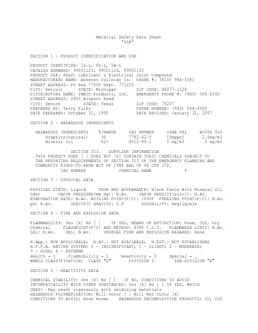
Material Safety Data Sheet*ZLB*SECTION 1 - PRODUCT IDENTIFICATION AND USEPRODUCT IDENTIFIER: 1Z-L, 8Z-L, 5B-LCATALOG NUMBERS: 99001123, 99001124, 99001125PRODUCT USE: Shaft Lubricant & Electrical Joint CompoundMANUFACTURERS NAME: Acheson Colloids Co. PHONE #: (810) 984-5581STREET ADDRESS: PO Box 77000 Dept. 771226CITY: Detroit STATE: Michigan ZIP CODE: 48277-1226DISTRIBUTORS NAME: TWECO Products, Inc. EMERGENCY PHONE #: (940) 566-2000STREET ADDRESS: 2800 Airport RoadCITY: Denton STATE: Texas ZIP CODE: 76207PREPARED BY: Terry Fulks PHONE NUMBER: (940) 566-2000 DATE PREPARED: October 31, 1990 DATE REVISED: January 31, 2007SECTION 2 - HAZARDOUS INGREDIENTSHAZARDOUS INGREDIENTS %/RANGE CAS NUMBER OSHA PEL ACGIH TLVGraphite(natural) 30 7782-42-5 15mppcf 2.5mg/m3 Mineral Oil 62+ 8012-95-1 5 mg/m3 5 mg/m3SECTION 313. SUPPLIER INFORMATIONTHIS PRODUCT DOES [ ] DOES NOT [X] CONTAIN TOXIC CHEMICALS SUBJECT TOTHE REPORTING REQUIREMENTS OF SECTION 313 OF THE EMERGENCY PLANNING ANDCOMMUNITY RIGHT-TO-KNOW ACT OF 1986 AND OF 40 CFR 372.CAS NUMBER CHEMICAL NAME %SECTION 3 - PHYSICAL DATAPHYSICAL STATE: Liquid ODOR AND APPEARANCE: Black Paste With Mineral OilOdor VAPOR PRESSURE(mm Hg): N.Av. VAPOR DENSITY(air=1): N.Av.EVAPORATION RATE: N.Av. BOILING POINT(F/C): >600F FREEZING POINT(F/C): N.Av.pH: N.Av. SPECIFIC GRAVITY: 0.9 SOLUBILITY: NegligibleSECTION 4 - FIRE AND EXPLOSION DATAFLAMMABILITY: Yes [X] No [ ] IF YES, MEANS OF EXTINCTION: Foam, CO2, DryChemical FLASHPOINT(F/C) AND METHOD: 450F C.O.C. FLAMMABLE LIMIT: N.Av.LEL: N.Av. UEL: N.Av. UNUSUAL FIRE AND EXPLOSION HAZARDS: NoneN.App.: NON APPLICABLE; N.AV.: NOT AVAILABLE; N.EST.: NOT ESTABLISHEDN.F.P.A. RATING SYSTEM: 0 - INSIGNIFICANT; 1 - SLIGHT; 2 - MODERATE;3 - HIGH;4 - EXTREMEHealth = 1 Flammibility = 1 Reactivity = 0 Special = _WHMIS CLASSIFICATION: CLASS "D" DIVISION 2 SUB-DIVISION "B"SECTION 5 - REACTIVITY DATACHEMICAL STABILITY: Yes [X] No [ ] IF NO, CONDITIONS TO AVOIDINCOMPATIBILITY WITH OTHER SUBSTANCES: Yes [X] No [ ] IF YES, WHICHONES? May react vigorously with oxidizing materialsHAZARDOUS POLYMERIZATION: Will Occur [ ] Will Not Occur [X]CONDITIONS TO AVOID: None known HAZARDOUS DECOMPOSITION PRODUCTS: CO, CO2ZLB Page 2SECTION 6 - HEALTH HAZARD DATAROUTE OF ENTRY: SKIN CONTACT [ ] SKIN ABSORPTION [X] EYE CONTACT [X]INHALATION [X] INGESTION [ ]EFFECTS OF ACUTE/CHRONIC EXPOSURE TO PRODUCT: Irritation of the eyes,Dermatitis CARCINOGENICITY: No SIGNS AND SYMPTOMS OF EXPOSURE: Irritationof the skin and eyes MEDICAL CONDITIONS GENERALLY AGGRAVATED BY EXPOSURE: Pre-existing skin disorders EMERGENCY AND FIRST AID PROCEDURES: SKIN: Washthoroughly with soap and water EYES: Flush immediately with water for15 minutes, get medical attention. INGESTION: No ill effects expectedINHALATION: No ill effects expectedSECTION 7 - PRECAUTIONS FOR SAFE HANDLING AND USELEAK AND SPILL PROCEDURE: Remove any source of ignition, scoop up as much aspossible, cover remainder with absorbent material & place in non-leakingcontainer for disposal. WASTE DISPOSAL METHOD: Dispose of in accordance withFederal, State & Local regulationsPRECAUTIONS TO BE TAKEN IN HANDLING AND STORING: Store away from sparks, openflames, or excessive heatSECTION 8 - CONTROL MEASURESRESPIRATORY PROTECTION: Not needed for this product. As required for cuttingand welding. GLOVES: Oil resistant RESPIRATOR: not needed EYE: Safetyor chemical goggles FOOTWEAR: N.App. CLOTHING: As required for weldingOTHER: N.Est.VENTILATION: Not normally needed WORK/HYGIENIC PRACTICES: Normal HygieneREFERENCES:"Chemical Guide To OSHA Hazard Communication Standard" First Edition"Handbook Of Toxic And Hazardous Chemicals and Carcinogens" Second Edition "Registry Of Toxic Effects Of Chemical Substances""NIOSH Pocket Guide to CHEMICAL HAZARDS" June 1994THIS DATA IS OFFERED IN GOOD FAITH AS TYPICAL VALUES. THIS IS NEITHER ANEXPRESSED NOR IMPLIED PRODUCT SPECIFICATION. RECOMMENDED HANDLING PROCEDURESAND HYGIENE ARE BELIEVED TO BE ACCURATE, HOWEVER, THESE RECOMMENDATIONS SHOULDBE REVIEWED IN THE SPECIFIC CONTEXT OF INTENDED USE AND DETERMINED APPROPRIATEBY THE USER.。
IND256x 服务手册R02

3.6. 应用..................................................... 46
3.6.1. 存储器.............................................................. 46 3.6.2. 应用分配............................................................ 50 3.6.3. 累计................................................................ 53 3.6.4. 交易计数............................................................ 54 3.6.5. 复位................................................................ 54
数据输入................................................. 15 主窗口................................................... 16
3. 3.1.
3.1.1
3.2. 3.3.
3.3.1. 3.3.2.
3.4.
1.8. 电源模块.................................................. 8
Agilent 8890 5977C Series gas chromatograph mass s

Agilent 5977C GC/MSD SystemThe Agilent 8890/5977C Series gas chromatograph/mass selective detector (GC/MSD) builds on a tradition of leadership in GC and MS technology, with the world’s most competitive performance and productivity features.Agilent GC/MSD system featuresAgilent 5977C GC/MSD — the most sensitive and robust MSD provides:–Four EI source options including the revolutionary high-efficiency source (HES), which offers the industry’s lowest instrument detection limit (IDL) and bestcarrier gas applications.signal-to-noise ratio (S/N) and a HydroInert source for H2– A heated monolithic quartz gold quadrupole (heatable up to 200 °C) for rapid elimination of contamination to keep the analyzer clean.– A second-generation triple-axis detector (TAD) for eliminating neutral noise.–Scan speeds up to 20,000 u/sec (extractor ion source and HES).–An optional oil-free IDP-3 roughing pump: a cleaner, quieter, and greener alternative (for use with turbo molecular pump systems).10-Year value promiseSupport is guaranteed for 10 years from the date of purchase, or Agilent will provide credit for the residual value of the system toward a model upgrade.Installation checkout specifications Agilent verifies GC/MSD system performance at the customer site.IDL is a statistically based metricthat more accurately confirms system performance than an S/N measurement. Test specificationsare based on splitless injection intoan Agilent J&W HP-5ms Ultra Inert30 m × 0.25 mm, 0.25 μm column for helium and a 20 m × 0.18 mm, 0.18 μm column for HydroInert with hydrogen. IDL analyses use lab helium (hydrogen for HydroInert) with GC gas filters installed. See more about the IDL test at /Library/ technicaloverviews/Public/5990-8341EN.pdf* IDL was statistically derived at 99% confidence level from the area precision of eight sequential splitless injections of OFN (octafluoronaphthalene). Demonstration of IDL specifications require a compatible system configuration, including a liquid autosampler with a 5 μL syringe.–HES IDL was measured using 10 fg injection, 1 µL injection.–Other IDLs were measured using 100 fg, 1 µL injection.–A 30 m column was used for helium IDL checkout; a 20 m column was used for hydrogenIDL checkout.–Helium carrier gas for Installation Specifications of the HES, Extractor, and Stainless steel sources; hydrogen carrier gas for Installation Specification of the HydroInert source only.–Reference IDL specifications from the above table will be confirmed only when purchased as an additional service with a compatible new system (GC and MS) installation.Signal-to-noise (S/N) specificationsa S/N checkout is performed only if there is no compatible autosampler (which is required for IDL checkout). Helium carrier gas, manual injection using a 30 m × 0.25 mm,0.25 µm column and in scan mode. Hydrogen carrier gas, manual injection using 20 m × 0.18 mm, 0.18 µm column and in scan mode. When the autosampler (ALS) is present, these specifications are a reference of the performance. Reference S/N specifications from the above table will not be confirmed at installation or introduction for ALS equipped systems.b Standard scanning from 50 to 300 u at nominal 272.0 u ion.c 1 μL injection of 100 pg/μL benzophenone (BZP) standard, 80 to 230 u scan at nominal 183 u ion, using methane reagent gas.d 2 μL injection of 100 fg/μL OFN standard scanning from 50 to 300 u at nominal 272 u ion, using methane reagent gas.2a Only applicable with optional Accurate Mass software package. Scan mode only. Not verified during installation.b As scan rate increases, sensitivity will decrease, and resolution may degrade.c A high flow rate into a fixed ion source will cause a loss in sensitivity.d The heated quadrupole mass filter should not require maintenance, but if maintenance is required, it should be performed by an Agilent service engineer.34aInlet temperature should be cool enough to touch when performing maintenance.bA micro ion gauge is shipped standard for the CI system, and is available optionally for EI systems.DE67854286This information is subject to change without notice.© Agilent Technologies, Inc. 2022Printed in the USA, May 26, 20225994-4846EN。
SMD3说明

一. 元件數據的輸入(Part Data Entry for SMD3 <F4G Ver.> )1PD(part data)必須輸入的項目:a. the nozzle size (吸嘴尺寸)b. camera type (相機類型)c. the vision type (影像模型類型)d. several item in tolerance_information and EL_data in case of leads parts(部分項目公差和電氣參數<對於有引腳的元件> )2necessary Part Data items (零件數據必須的項目)<1> reference data (參考數據)a. type name (類型名稱)b. package name (包裝名稱)c. direction (包裝方向)d. 90 turn to read (轉90度後再讀取參數)<2>vision data (影象數據)a. vision type (影象類型) f. pitch Limit (間距極限)b. body X and Y Size (本體X和Y方向尺寸)g. height (元件高度<適用于HP機器> )c. body X and Y tolerance (本體公差)h. scan Area X and Y (X和Y掃描區域)d. check window area (檢查窗口區域)i. Lead btihtness (引腳亮度)e. check Limit (檢查極限)<3>check mode (檢查方式)a. check mode (檢查方式)b. CCD Level (CCD相機亮度)c. check area X1,X2,Y1,Y2 (掃描設定的窗口)d. body color (本體色彩)e. algorithm (計算規則)<4>Tolerance__information (公差信息)a. body size X and Y tol. (本體公差)b. tolerance lead width (引腳寬度公差)c. tolerance lead length (引腳長度公差)d. check Limit (檢查極限)e. tolerance pickup X & Y & Q (拾取X,Y及角度公差)e. check Limit (檢查極限)<5>EL_data (Element data ) <電氣數據>a. side # ( 側邊序列號) f. lead length (引腳長度)b. position X and Y (X和Y方向的位置)g. lead width tol. (引腳寬度公差)c. lead quantity (引腳數量)h. lead length tol. (引腳長度公差)d. lead pitch (引腳間距)i. Lead center tol. (引腳中心公差)e. lead width (引腳寬度)<6>environment (環境設定)a. M/C type (機器類型) f. nozzle size max (最大吸嘴尺寸)b. nozzle type (吸嘴類型)g. camera (相機)c. nozzle name (吸嘴名稱)h. camera type (相機類型)d. nozzle size (吸嘴尺寸)i. Lighting (亮度)e. nozzle size min (最小吸嘴尺寸)j. back light min (最小反光盤尺寸)3Vision Data (影像數據)<1>direction algorithm (方向定義)side "0" (左) side 1 (下) side 2 (右) side 3 (上)<2>parts type data (零件類型數據)a. vision type (1~255)機器使用16進制編碼原則, 取兩位即16的平方256(除去缺省"0"即為255)b. check window Area ( 0 ~~100 % ) {檢查窗口區域)從引腳末端開始計算(以引腳總長作比例)SOP & QFP : 10 ~~ 90 % (Setting 30 % )PLCC & SOJ : 50 ~~ 70 % (Setting 60% )BGA & Flip chip : 50 %c. pitch limit ( 0 ~~ 100 % ) 間距誤差 {如果不輸入則等于預設30%}d. lead brigtness ( 0 ~255 ) 引腳亮度在BGA元件輸入"0"時將自動確定;若輸入 1 ~ 255 時則按輸入值進行測定4Vision TYPE (影像類型)<1>兩种不同的參考點零件本體中心 : 按PD本体設定的尺寸來進行影像處理計算坐標置件的位置參考點零件中心 : 按PD設定的引腳尺寸或影像測得的平面數據計算置件坐標的元件中心點(有一邊,三邊或部分不對稱引腳BGA類元件本體中心与零件中心不重合)<2>目前G-COM最常用的影像類型10矩形(適用於所有無引腳之矩形元件)12甜甜圈 (橢圓形) 即 odd,MELF (如二極體,電容適用)20SOT Type (適用于電晶体,晶閘体,兩邊引腳<引腳數雙邊和小于等于6)100IC類元件 ( 使用背光<BackLight> )120PLCC (適用於四面引腳內卷式元件)123IC類元件 (使用黑色吸嘴,前光)230BGA ( 錫球陣列引腳類元件<可帶孔> )254不規則元件,只檢查零件中心,且作校正置件處理255只檢查有無元件,不作影像檢查校正處理( F.L=Front Lighting B.L=Back Lighting BG=Background )未加括號的以零件本體中心為參考點,加括號的則以零件中心為參考點5Algorithm ( 影像類型算法規則詳細描述 )<1>10 Rectangular chips (矩形元件)<2>12 Resistor networks , MELFs , Glass tube diodes (排阻,圓形倒角矩形,桶形玻璃二極体)( 只需要本體尺寸即可,不需要EL_data )<3>11Tantalum spragues (條狀鉭質電容類)13Tantalum spragues (with polarity check) <相對於11增加極性檢查><3>20 SOT__Type devices (SOT類元件)說明: 不能用於電源三極管 , 四引腳SOTs和其它有極性元件如果20影像不適當可用100代替( CP6 , IP_3E & QP242E )<4>21 Trimmer resistor , Trimmer capacitors (微調電阻,微調電容)(同10,長度計算包括引腳在內)<5>22HEMT (Supplied at 0度 )23HEMT (Supplied at 45度 )(十字形元件,規則同10,但需輸入EL__data )<6>24 Trimmer Resistor , Trimmer Capacitor (with polarity check )(需輸入BodySize和EL_data ,計算BodySize時不包括引腳長度,且只適于2或3條引腳類元件)<7>30 Round shape parts (圓形零件 <無方向> )<8>40 Body detection processing ( 本体偵測處理) 使用白色反光盤(需輸入BodySize和EL_data)<9>100(105) IC - Type parts ( IC類元件)使用白色反光盤,光源用背光<10>120 (125) J_lead parts (F.L 1 Background : White ) 引腳內彎式元件 <用前光,白色反光盤>121 (126) J_lead parts (F.L 2 Background : White ) 引腳內彎式元件 <用前光,白色反光盤> 122 (127) J_lead parts (F.L 3 Background : White ) 引腳內彎式元件 <用前光,白色反光盤>注:120(125) :Used for that are larger than the reflective disk (適於零件大於反光盤) 121(126) :Used for that are smaller than the reflective disk (適於零件小於反光盤)122(127) :Used for that are larger than the reflective disk (適於零件大於反光盤)( 若122不能影像可改用120 )<11>123(128) IC - Type parts (F.L) IC類元件 (用前光)124(129) J - lead parts (F.L) 引腳內彎式元件 (用前光)注: 需使用黑色反光盤的吸嘴,且必須輸入BodySize和EL_data<12>130(135) Black body BGAs (F.L) 黑色本體類BGA (用前光)131(136) White body BGAs (F.L) 白色本體類BGA (用前光)需使用黑色反光盤的吸嘴,且必須輸入BodySize和EL_data如有以下類似情形影像處理將不能通過:a. Device for which there are variations in the body color or the image of the ball grid(本體顏色或錫球顏色是變化不確定的裝置)b.Devices for which is difficult to distinguish between the body and the ball grid(本體和錫球之間辨識困難的白色本體裝置)c. Devces with no ball grid art the center of the body(本體中心沒有錫球的裝置<即錫球面非全點陣,帶有空位> )d. Devices which have a pattern on the bottom surface(在反面<非錫球面>有圖案模型的裝置 )<13>140(145) Flip chips (F.L)需使用黑色反光盤的吸嘴,且必須輸入BodySize和EL_data<14>150(155) M/C chuck (B.L BG : White )151(156) M/C chuck (F.L BG: Black )152(157) Black body parts inspected (F.L BG: Black )153(158) White body parts inspected (F.L BG: Black )154 M/C chuck part exsitance chuck inspected with back lighting159 M/C chuck part exsitance chuck inspected with front lighting(154,159必須在置件前檢查PCB上的元件定位Mark點)以上均為IP-3(E)裝機械式夾子時所使用之影像類型,此處略過<15>160(165) body detection (F.L) 本體偵測 <用於校正機器讀處理的時間>需使用黑色反光盤的吸嘴,且必須輸入BodySize和EL_data<16>170 Mechanical chuck part existence check (F.L) 用於IPC-3(E)使用電磁吸盤時<17>180(185) Two lead parts (F.L BG: Black ) 兩個(對)引腳的零件 <用前光,黑色吸嘴>用於處理引腳光亮,本體為黑色且有兩個或兩對對稱引腳的元件注意: a. 元件引腳最大為4,大於4不能完成影像處理b. 引腳局部亮度或亮度不均勻均不能完成影像處理c. 用nozzle時在NAT data或proper data之nozzle項目輸入一個近似於零件兩倍的尺寸數據<18>230(235) Black body BGAs (F.L)黑色本體BGA (用前光)231(236) White body BGAs (F.L)白色本體BGA (用前光)233(238) Black body CSPs (F.L)黑色本體CSP (用前光)234(239) White body CSPs (F.L)白色本體CSP (用前光)設定零件數據之步驟與130和131一樣,除在EL_data結果(Result)項目輸入"9"代替"1"230,231,235,236檢測選Cut(切角),check Area X1,X2,Y1,Y2為左上角和右下角的窗口定位點<19>232(237) TBGAs (F.L BG: White ) 帶邊框的BGA <前光,白色反光盤)僅用於IP-3(E) ,需輸入BodySize和EL_data注: 靠邊框不可以設定有錫球(在EL_data)<20>249 Diagonal cut_shield processing (斜角屏處理)適用於有一條線段(邊)直線和斜線比大於50%的元件,如果斜邊比率小於50%斜邊數量沒有限定,位置不作限定,(254在有斜邊的元件處理時會產生角度偏移)(需輸入BodySize和Side_data,不需EL_data )check window Area 輸入為 "0" , P parttern設為 "2" , Result 設為 "1"<21>250 QP242E Coplanarity check jig (F.L)(QP242前光共面性檢查治具使用)<22>252 White parts (F.L) 白色零件 <前光>(適用於白色和金色本體元件,處理時尋找四個角點進行)<23>253 Dummy data settings (用於檢查機器的影像處理操作)測試影像處理時間及校正反應時間和校正精度<24>254 Ierregular - shaped devices (不規則類型裝置)只尋找X,Y尺寸及元件中心作位置校正處理<25>255 No correction processing (不校正處理)只作檢查有無元件,不檢查方向,不作校正處理二Tolerance information (公差信息處理規則)1body size X , Y tolerance (本體X,Y方向公差)(個別元件近似等于10% , 最小值為 0.2 mm 最大值為2.0mm 2Tolerance lead width (length) (此項目SMD3不需要輸入)3Tolerance pickup X , Y , Q (零件拾取誤差)(輸入在50 ~~ 100 % 之間<零件本體的>,最大值2.0mm,最小值0.5mm 4check limit (輸入引腳可偵測結果可接受的比例 )三EL_data (電氣數據輸入規則)12Result (測試結果)Setting Input value No lead inspection(不偵測)0Lead inspection (偵測)1No lead length inspection(不偵測引腳長度)4No lead width inspection(不偵測引腳寬度)8Right side exta lead inspection (右側突出部偵測)32Left side exta lead inspection (左側突出部偵測)16Virtual lead inspection (虛擬引腳偵測)2Second line of mnatrix_type(點陣類的第二條線偵測)128四Error code of vision processing (影像處理錯誤代碼)1錯誤代碼類型說明1CAXXXXX :Inspection parts(零件影像偵測錯誤代碼)1CB01XXX :Calibration(機器校正錯誤代碼)1CB02XXX :Nozzle centering(吸嘴中心偵測錯誤代碼)1CB03XXX :Inspection fiducial marks (基準點偵測錯誤代碼)1CCXXXXX :Performing Fst-pin check (IP-3(E)第一腳偵測錯誤代碼) 2錯誤代碼編碼原則1C A XX XXX1C: Vision processing error (影像處理錯誤)A: Type of process (處理類型)XX: Vision processing algorithm ( 01 ~ FF ) <影像處理計算規則代碼XXX: Error nubmers for each algorithm ( 000 ~ FFF ) <每個規則代碼的錯誤代碼序列號>五部分專用名詞解釋QFP : quad flat package 四方形低平式包裝PLCC: Plastic leaded chip carrier塑膠平貼式引腳托架SOIC : Small outline intergrate circuit小型綜合線路SOJ : Small outline J-lead小型"J"型引腳器件(P)BGA: Ball grid array球型陣列包裝SOP: Small outline package小輪廓型包裝QFP, SOIC,SOP PLCC BGA SOJ。
22756641_时尚新品

142Clixo新3D构建玩具设计
Copyright©博看网 . All Rights Reserved.
图表解读
15
WORLD VISION 2020.NO.23
时尚新品
仅重35磅,装箱后尺寸为16×23×8英寸,可以将它存放在壁橱、办公室桌子下或汽车后备箱里。
使用时将其打开,调整高度和手把,设置所需阻力就可以进行锻炼了。
除此之外,这款自行车还配有蓝牙模块,可与同步移动设备,在Strava和Apple Health等培训应用程序以及自
己的Breakaway应用程序中跟踪锻炼情况。
拟人化设备。
热量会从其“面部”散发出来;它的背面有进气口,由此吸入冷空气,经过内部线圈将空气加热,最终从正面输出。
加热器侧面有一个旋钮切换键,可控制设备的温度。
这个外观酷酷的加热
器,将为你的冬季生活带来温暖。
指下方的轨迹球就可以,并且位置精准。
鼠标右键有单击按钮,中间有一个滚轮,还有两个额外的可编程按钮,它们都在食指触及的范围内。
此功能鼠标不仅可以节省能源,还可以提供额外的桌面空间,因为你不再需要任何多余的地方移动鼠标。
Copyright©博看网 . All Rights Reserved.。
硝苯地平缓释片(II)CTD资料

注册分类第1 页共126 页上海玉瑞生物科技(安阳)药业有限公司硝苯平缓释片(Ⅱ)申报生产资料 模块 --3.2.P.5 制剂质量控制CTD第 2 页 共 126页表 3.2.P.5.3.2-2 鉴别(二)保留时间统计表表 3.2.P.5.3.3.3.1-2 中国药典流动相(甲醇 - 水( 60:40))实验结果注:峰纯度合格标准:纯度角度<纯度阈值。
结论:中国药典流动相中酸破坏样品杂质Ⅰ峰、杂质Ⅱ峰纯度不合格,且杂质Ⅰ峰与前杂质峰分离度不合格。
碱破坏样品杂质Ⅰ峰纯度不合格表 3.2.P.5.3.3.3.1-3美国药典流动相(乙腈 - 甲醇 - 水( 50:25:25))实验结果上海玉瑞生物科技(安阳)药业有限公司硝苯平缓释片(Ⅱ)申报生产资料CTD 模块--3.2.P.5 制剂质量控制注:峰纯度合格标准:纯度角度<纯度阈值。
结论:美国药典流动相中光照破坏样品杂质Ⅰ峰纯度不合格,酸破坏样品杂质Ⅰ峰纯度不合格,且杂质Ⅰ峰与前杂质峰分离度不合格。
碱破坏样品杂质Ⅱ峰纯度不合格。
; 表3.2.P.5.3.3.3.1-4英国药典流动相(乙腈- 甲醇- 水(9:36:55))实验结果第3 页共126页上海玉瑞生物科技(安阳)药业有限公司硝苯平缓释片(Ⅱ)申报生产资料 模块 --3.2.P.5 制剂质量控制CTD第 4 页 共 126页注:峰纯度合格标准:纯度角度<纯度阈值。
结论:各破坏样品溶液中,主峰、杂质Ⅰ、Ⅱ与前后峰分离度均符合规定,峰纯度均符合要求,但主峰保留时间达到 时间可能过长。
45分钟, 后续可能杂质洗脱上海玉瑞生物科技(安阳)药业有限公司硝苯平缓释片(Ⅱ)申报生产资料 模块 --3.2.P.5 制剂质量控制第 5 页 共 126 页CTD① 中国药典流动相改进 总流速 :1.0ml/min 流动相:甲醇 - 水(45:55)表 3.2.P.5.3.3.3.2-2中国药典流动相改进(甲醇:水 -45 :55)注:峰纯度合格标准:纯度角度<纯度阈值。
Pyxis Lab ST-588 PTSA Fluorescent Polymer Dual Inl
ST-588PTSA/Fluorescent Polymer DualInline SensorUser ManualOctober12,2020Rev.2.00Pyxis Lab,Inc.1729Majestic Dr.Suite5Lafayette,CO80026USA©2017Pyxis Lab,Inc.Pyxis Lab Proprietary and ConfidentialTable of Contents1Introduction21.1Main Features (2)2Specifications3 3Unpacking Instrument43.1Standard Accessories (4)3.2Optional Accessories (5)4Installation64.1ST-588Piping (6)4.2ST-588SS Piping (6)4.3Wiring (7)4.4Connecting via Bluetooth (8)4.5Connecting via USB (8)5Setup and Calibration with uPyxis®Mobile App95.1Download uPyxis®Mobile App (9)5.2Connecting to uPyxis®Mobile App (9)5.3Calibration Screen and Reading (10)5.4Diagnosis Screen (11)5.5Device Info Screen (12)6Setup and Calibration with uPyxis®Desktop App126.1Install uPyxis®Desktop App (12)6.2Connecting to uPyxis®Desktop App (13)6.3Information Screen (13)6.4Calibration Screen (14)6.5Diagnosis Screen (14)7Outputs157.14–20mA Output Setup (15)7.2Communication using Modbus RTU (15)8Sensor Maintenance and Precaution158.1Methods to Cleaning the ST-588 (16)8.2Storage (16)9Troubleshooting17 10Contact Us18Warranty InformationConfidentialityThe information contained in this manual may be confidential and proprietary and is the property of Pyxis Lab,rmation disclosed herein shall not be used to manufacture,construct,or otherwise reproduce the goods rmation disclosed herein shall not be disclosed to others or made public in any manner without the express written consent of Pyxis Lab,Inc.Standard Limited WarrantyPyxis Lab warrants its products for defects in materials and workmanship.Pyxis Lab will,at its option,repair or replace instrument components that prove to be defective with new or remanufactured components (i.e.,equivalent to new).The warranty set forth is exclusive and no other warranty,whether written or oral, is expressed or implied.Warranty TermThe Pyxis warranty term is thirteen(13)months ex-works.In no event shall the standard limited warranty coverage extend beyond thirteen(13)months from original shipment date.Warranty ServiceDamaged or dysfunctional instruments may be returned to Pyxis for repair or replacement.In some in-stances,replacement instruments may be available for short duration loan or lease.Pyxis warrants that any labor services provided shall conform to the reasonable standards of technical com-petency and performance effective at the time of delivery.All service interventions are to be reviewed and authorized as correct and complete at the completion of the service by a customer representative,or des-ignate.Pyxis warrants these services for30days after the authorization and will correct any qualifying deficiency in labor provided that the labor service deficiency is exactly related to the originating event.No other remedy,other than the provision of labor services,may be applicable.Repair components(parts and materials),but not consumables,provided during a repair,or purchased individually,are warranted for90days ex-works for materials and workmanship.In no event will the in-corporation of a warranted repair component into an instrument extend the whole instrument’s warranty beyond its original term.Warranty ShippingA Repair Authorization(RA)Number must be obtained from Pyxis Technical Support before any product can be returned to the factory.Pyxis will pay freight charges to ship replacement or repaired products to the customer.The customer shall pay freight charges for returning products to Pyxis.Any product returned to the factory without an RA number will be returned to the customer.To receive an RMA you can generate a request on our website at https:///request-tech-support/.Pyxis Technical SupportContact Pyxis Technical Support at+1(866)203-8397,*********************,or by filling out a request for support at https:///request-tech-support/.1IntroductionThe Pyxis ST-588inline fluorometer probe simultaneously measures the concentration of PTSA and Fluores-cent Polymer in water.It can be simply inserted to the compression fitting port of a custom-made tee.The standard ST-001installation tee provided with each ST-588sensor,has two¾inch female NPT ports and can be placed to an existing¾inch sample water line.Pyxis Lab also offers2”and3”Tee formats for larger flow installations.The4–20mA current output of the ST-588probe can be connected to any controller that accepts an isolated or non-isolated4–20mA input.The ST-588probe is a smart device.In addition to mea-suring PTSA and Fluorescent Polymer,the ST-588probe has extra photo-electric components that monitor the color and turbidity of the sample water.This extra feature allows automatic color and turbidity com-pensation to eliminate interference commonly associated with real-world waters.The Pyxis ST-588probe has a short fluidic channel and can be easily cleaned.The fluidic and optical ar-rangement of the ST-588probe is designed to overcome shortcomings associated with other fluorometers that have a distal sensor surface or a long,narrow fluidic cell.Traditional inline fluorometers are susceptible to color and turbidity interference and fouling and are difficult to properly clean.1.1Main FeaturesThe ST-588measures PTSA and Fluorescent Polymer in a water sample and includes the following features:•Easy calibration with using uPyxis®Mobile or Desktop App.•Automatic compensation for turbidity up to150NTU and color created by up to10ppm iron or equivalent to10ppm humic acid.•Diagnostic information(probe fouling,color or turbidity over range,failure modes)are available in uPyxis®App or via Modbus RTU.•Easy to remove from the system for cleaning and calibration without the need for any tools.2SpecificationsTable1.ST-588Specifications*With Pyxis’s continuous improvement policy,these specifications are subject to change without notice.†The fluorescent polymer concentration scale is based on the polymer containing0.25mole%fluorescent monomer.Typical polymer specifications are attached below but may vary by producer.‡See Figure4for ST-588SS dimensions.3Unpacking InstrumentRemove the instrument and accessories from the shipping container and inspect each item for any damage that may have occurred during shipping.Verify that all accessory items are included.If any item is missing or damaged,please contact Pyxis Lab Customer Service at*********************.3.1Standard Accessories•Tee Assembly3/4”NPT(1x Tee,O-ring,and Nut)P/N:ST-001*NOTE*ST-001is not included for ST-588SS•8-Pin Female Adapter/Flying Leads Cable(1.5ft)•User Manual available online at https:///support/3.2Optional AccessoriesFigure1.4Installation4.1ST-588PipingThe provided ST-001Tee Assembly can be connected to a pipe system through the3/4”female ports,either socket or NPT threaded.To properly install the ST-588probe into the ST-001Tee Assembly,follow the steps below:1.Insert the provided O-ring into the O-ring groove on the tee.2.Insert the ST-588probe into the tee.3.Tighten the tee nut onto the tee to form a water-tight,compression seal.Figure2.Dimension of the ST-588and the ST-001Tee Assembly(mm)4.2ST-588SS PipingThe ST-588SS probe has3/4”female NPT threaded ports on the probe itself and therefore does not require a custom tee assembly.It is recommended that two3/4”NPT to1/4”tubing adapters are used to connect the probe to the sampling system.Sample water entering the probe must be cooled down to below104°F (40°C).The probe can be held by a1.75-inch pipe clamp or mounted to a panel with four1/4-28bolts.See Figure4for ST-588SS dimensions.Figure3.Dimension of the ST-588SS(inch)4.3WiringIf the power ground terminal and the negative4–20mA terminal in the controller are internally connected (non-isolated4–20mA input),it is unnecessary to connect the4–20mA negative wire(gray)to the4–20mA negative terminal in the controller.If a separate DC power supply other than that from the controller is used,make sure that the output from the power supply is rated for22–26VDC@85mA.*NOTE*The negative24V power terminal(power ground)and the negative4–20mA ter-minal on the ST-588probe are internally connected.Follow the wiring table below to connect the ST-588probe to a controller:Table2.*Internally connected to the power ground4.4Connecting via BluetoothA Bluetooth adapter(P/N:MA-WB)can be used to connect a ST-588probe to a smart phone with the uPyxis®Mobile App or a computer with the uPyxis®Desktop App.Figure4.Bluetooth connection to ST-588probe4.5Connecting via USBA USB-RS485adapter(P/N:MA-485)can be used to connect a ST-588probe to a computer with the uPyxis®Desktop App.*NOTE*Using non-Pyxis USB-RS485adapters may result in permanent damage of the ST-588probe communication hardware.B connection to ST-588probe5Setup and Calibration with uPyxis®Mobile App5.1Download uPyxis®Mobile AppDownload uPyxis®Mobile App from Apple App Store or Google Play.Figure6.5.2Connecting to uPyxis®Mobile AppTurn on Bluetooth on your mobile phone(Do not pair the phone Bluetooth to the ST-588probe).Open uPyxis®Mobile App.Once the app is open the app will start to search for the sensor.Once the uPyxis®Mobile App connects to the sensor,press the ST-588probe.Figure7.5.3Calibration Screen and ReadingWhen connected,the uPyxis®Mobile App will default to the Calibration screen.From the Calibration screen,you can perform calibrations by pressing on Zero Calibration,Slope Calibration,and4–20mA Span for either Fluorescent Polymer or PTSA,independently.Follow the screen instructions for each calibration step.Figure8.5.4Diagnosis ScreenFrom the Diagnosis screen,you can check the diagnosis condition.This feature may be used for technical support when communicating with*********************.To preform a probe cleaniness check,first select the Diagnosis Condition which defines the fluid type that the ST-588probe in currently measuring,then press Cleanliness Check.If the probe is clean,a Clean mes-sage will be shown.If the probe is severely fouled,a Dirty message will be shown.In this case,follow the procedure in the Methods to Cleaning the ST-588section of this manual.Figure9.5.5Device Info ScreenFrom the Device Info screen.You can name the Device or Product as well as set the Modbus address.Figure10.6Setup and Calibration with uPyxis®Desktop App6.1Install uPyxis®Desktop AppDownload the latest version of uPyxis®Desktop software package from:https:///upyxis/this setup package will download and install the Framework4.5(if not previously installed on the PC),the USB driver for the USB-Bluetooth adapter(MA-NEB),the USB-RS485adapter(MA-485),and the main uPyxis®Desktop application.Double click the uPyxis.Setup.exe file to install.Figure11.Click Install to start the installation process.Follow the screen instructions to complete the USB driver and uPyxis®installation.6.2Connecting to uPyxis®Desktop AppWhen the uPyxis®Desktop App opens,click on Device,then click either Connect via USB-Bluetooth or Connect via USB-RS485depending on the connection type.Figure12.6.3Information ScreenOnce connected to the device,a picture of the device will appear on the top left corner of the window and the uPyxis®Desktop App will default to the Information screen.On the Information screen you can set the information description for Device Name,Product Name,and Modbus Address,then click Apply Settings to save.Figure13.6.4Calibration ScreenTo calibrate the device,click on Calibration.On the Calibration screen there are six calibration options:•Fluorescent Polymer:Zero Calibration,Slope Calibration,and4-20mA Span•PTSA:Zero Calibration,Slope Calibration,and4-20mA SpanThe screen also displays the reading of the device.The reading refresh rate is every4seconds.Figure14.6.5Diagnosis ScreenAfter the device has been calibrated and installation has been completed,to check diagnosis,click on Di-agnosis.When in the Diagnosis screen you can view the Diagnosis Condition of the device.This feature may be used for technical support when communicating with*********************.To preform a probe Cleaniness Check,first select the Diagnosis Condition which defines the fluid type that the ST-588probe inCheck.If the probe is clean,a Clean message will be shown.message will be shown.In this case,follow the procedure in theof this manual.Figure15.7Outputs7.14–20mA Output SetupThe4–20mA output of the ST-588sensor is scaled as:•Fluorescent Polymer:–4mA=0ppm–20mA=20ppm•PTSA:–4mA=0ppb–20mA=200ppb7.2Communication using Modbus RTUThe ST-588probe is configured as a Modbus slave device.In addition to the ppm Fluorescent Polymer and ppb PTSA values,many operational parameters,including warning and error messages,are available via a Modbus RTU connection.Contact Pyxis Lab Customer Service(*********************)for more informa-tion.8Sensor Maintenance and PrecautionThe ST-588probe is designed to provide reliable and continuous Fluorescent Polymer and PTSA readings even when installed in moderately contaminated industrial cooling waters.Although the optics are com-pensated for the effects of moderate fouling,heavy fouling will prevent the light from reaching the sensor, resulting in low readings and the potential for product overfeed if the ST-588probe is used as part of an au-tomated control system.When used to control product dosing,it is suggested that the automation system be configured to provide backup to limit potential product overfeed,for example by limiting pump size or duration,or by alarming if the pumping rate exceeds a desired maximum limit.The ST-588probe is designed to be easily removed,inspected,and cleaned if required.It is suggested that the ST-588probe be checked for fouling and cleaned/calibrated on a monthly basis.Heavily contam-inated waters may require more frequent cleanings.Cleaner water sources with less contamination may not require cleaning for several months.The need to clean the ST-588probe can be determined by the Cleanliness Check using either the uPyxis®Mobile App(see the Mobile Diagnosis Screen section)or the uPyxis®Desktop App(see the Desktop Diagnosis Screen section).8.1Methods to Cleaning the ST-588Any equipment in contact with industrial cooling systems is subject to many potential foulants and con-taminants.Our inline probe cleaning solutions below have been shown to remove most common foulants and contaminants.A small,soft bristle brush,Q-Tips cotton swab,or soft cloth may be used to safely clean the probe housing and the quartz optical sensor channel.These components and more come with a Pyxis Lab Inline Probe Cleaning Solution Kit(P/N:SER-01)which can be purchased at our online Estore/Catalog https:///product/probe-cleaning-kit/Figure16.Inline Probe Cleaning Solution KitTo clean the ST-588probe,soak the lower half of the probe in100mL inline probe cleaning solution for 10minutes.Rinse the ST-588probe with distilled water and then check for the flashing blue light inside the ST-588probe quartz tube.If the surface is not entirely clean,continue to soak the ST-588probe for an e the small,soft bristle brush and Q-Tips cotton swabs as necessary to remove any remaining contaminants in the ST-588probe quartz tube.8.2StorageAvoid long term storage at temperature over100°F.In an outdoor installation,properly shield the ST-588 probe from direct sunlight and precipitation.9TroubleshootingIf the ST-588probe output signal is not stable and fluctuates significantly,make an additional ground con-nection––connect the clear(shield,earth ground)wire to a conductor that contacts the sample water electrically such as a metal pipe adjacent to the ST-588tee.Carry out routine calibration verification against a qualified Fluorescent Polymer and PTSA combined stan-dard.After properly cleaning the ST-588sensor,carry out the zero point calibration with distilled water and slope calibration using the qualified Fluorescent Polymer and PTSA combined standard.10Contact UsPyxis Lab,Inc1729Majestic Dr.Suite5Lafayette,CO80026USAPhone:+1(866)203-8397Email:*********************。
36202296
(0 5 0mg・ )t mb n t p rt e h dopi a aie rC (I ,C (I ,N ( 1 L a a i te ea r ,tea srt n cpc is o u I) d I) i 1 ) e m u o t f a dC ( I ee9 ,5 ,17 9 g・ ~,rset ey h t p li a hrcei db n r V )w r 9 6 ,1 8m 1 g ep c vl.T eat ug ew sc aat z y i a t re
o n i n na S i c ,N @ n 2 0 3 ,C ia f v o me t c n e a g 10 6 hn ) E r l e
Ab tac : Ata u gt s r sa l e y r td sr t tp lie i a c y tli h d ae ma n su n g e i m slc t wi b o s i a e t f r u mop lg i hi Байду номын сангаас hoo y, lr e ag
sann lc o irso e S M ) Fui rnf m if rdset so y ( I cn i e t nm coc p ( E , o r rt s r n ae p c ocp R)a da sr— g er e a o r r n dop
d i 0 3 6 / . s . 0 4— 9 7 2 1 . 0 0 o :1 . 9 9 ji n 10 4 5 . 0 0 1 . 2 s 2
Ap l a i n o t p l ie t s r t n o a y Me a o s p i to fAta u g t o Ad o p i fHe v t lI n c o
机械制图符及表示含义
机械制图符号及表示含义Solid 二维实体 2D 实面2D Wireframe 二维线框3D Array 三维阵列 3D 阵列3D Dynamic View 三维动态观察 3D 动态检视3d objects 三维物体 3D 物件3D Orbit 三维轨道 3D 动态3D Orbit 三维动态观察 3D 动态3D Studio 3D Studio 3D Studio3D Viewpoint 三维视点 3D 检视点3dpoly 三维多段线 3D 聚合线3dsin 3DS 输入 3D 实体汇入3DSolid 三维实体 3D 实体3dsout 3DS 输出 3D 实体汇出abort 放弃中断abort 中断中断absolute coordinates 绝对坐标绝对座标abut 邻接相邻accelerator key 加速键快速键access 获取存取acisin ACIS 输入 ACIS 汇入acisout ACIS 输出 ACIS 汇出action 操作动作active 活动的作用中adaptive sampling 自适应采样最适取样add 添加加入Add a Printer 添加打印机新增印表机Add mode 添加模式Add Plot Style Table 添加打印样式表Add Plot Style Table 添加打印样式表Add Plotter 添加打印机Add Plotter 添加打印机Add to Favorites 添加到收藏夹加入我的最爱ADI ADIAutodesk 设备接口 ADI Autodesk 设备介面adjacent 相邻相邻Adjust 调整调整Adjust Area fill 调整区域填充调整区域填满AdLM Autodesk License Manager AdLMAutodesk 许可管理器Administration dialog box 管理对话框管理对话方块Advanced Setup Wizard 高级设置向导进阶安装精灵Aerial View 鸟瞰视图鸟瞰视景affine calibration 仿射校准关系校正alert 警告警示alias 别名别名aliasing 走样锯齿化align 对齐对齐aligned dimension 对齐标注对齐式标注alignment 对齐方式对齐allocate 分配配置Altitude 标高高度ambient color 环境色环境颜色ambient light 环境光环境光源angular dimension 角度标注角度标注angular unit 角度单位角度单位annotation 注释注解anonymous block 无名块匿名图块anti-aliasing 反走样消除锯齿aperture 靶框锁点框apparent intersections 外观交点外观交点append 附加附加Application key 授权申请号应用程式码appload 加载应用程序载入应用程式Apply 应用/申请套用approximation points 近似点近似点arc 圆弧弧Architectual Ticks 建筑标记建筑斜线area 区域;面积区域 ;面积Argument 参数引数Arrange icons 排列图标排列图示array 阵列阵列arrowhead 箭头箭头ASCII ASCII 美国标准信息交换码 ASCII aseadmin ASE 管理 ASE 管理aseexport ASE 输出 ASE 汇出aselinks ASE 链接 ASE 连结aserows ASE 行 ASE 列aseselect ASE 选择 ASE 选取asesqled SQL 编辑 ASE SQL 编辑器Aspect 纵横向间距纵横向间距aspect ratio 宽高比纵横比assign 指定指定Assist 助理辅助associative dimension 关联标注关联式标注associative hatches 关联填充关联式剖面线attach v.附着贴附attdef 属性定义属性定义attdisp 属性显示属性显示attedit 属性编辑属性编辑attenuation 衰减衰减attenuation of light 灯光衰减光源衰减attext 属性提取属性萃取attredef 属性重定义属性重新定义attribute definition 属性定义属性定义Attribute Display 属性显示属性显示attribute extraction file 属性提取文件属性萃取档attribute extraction template file 属性提取样板文件属性萃取样板档attribute prompt 属性提示属性提示attribute tag 属性标签属性标签attribute value 属性值属性值audit 核查检核authorization code 授权码授权码AutoCAD library search path AutoCAD 库搜索路径 AutoCAD 资源库搜寻路径autocommit 自动提交自动确定AutoTrack 自动追踪自动追踪axis tripod 三轴架三向轴azimuth 方位角方位Back Clipping On 后向剪裁打开back view 后视图后视景background color 背景色背景颜色backup 备份备份Backward 反向左右反向bad 不正确的不正确base 基点基准;底端;底部base dimension 基准标注基线式标注base grips 基夹点基准掣点base point 基点基准点baseline 基线基准线基线式baseline dimension 基线标注基线式标注Basic color 基本色基本颜色batch plotting 批处理打印批次出图beam angles of spotlights 聚光灯光束角度点光源光线角度Beep on Error 出错报警错误时发出哔声bevel 倒角斜切bevel 倒角斜切beveling objects 斜角对象斜切物件Bezier curve Bezier 曲线 Bezier 曲线Big Font 大字体大字体bind 绑定并入bitmap 位图点阵图blend 合成混成blipmode 点标记模式点记模式block 块图块block definition 块定义图块定义block reference 块参照图块参考block table 块表图块表格bmpout BMP 输出 BMP 汇出body 体主体Boolean operation 布尔运算布林运算borders 边框图框bottom view 仰视图下视景boundary 边界边界boundary sets 边界集边界集bounding 边框边界框break v. 打断切断Bring Above Object 置于对象之上置于物件上方Bring to Top 顶置置于最上方brower 浏览器浏览器built-in 内置的内建bulge 凸度凸度bump map 凹凸贴图凸纹贴图button menu 按钮菜单按钮功能表BYBLOCK 随块 BYBLOCKBYLAYER 随层 BYLAYERbyte 字节位元组cabling 电缆布线配线cal 计算器校正calibrate 校准校正call 调用呼叫callback 回调for LISP 回覆callback 回叫回覆camera 相机照相机camera angle 相机角度相机角度Cancel 取消取消cap 封口封口cascade 层叠的重叠排列case 大小写大小写cast 投射投射catalog 目录目录cell 单元储存格Center 圆心中心center mark 圆心标记中心点标记centerline 中心线中心线centroid 形心;质心矩心chamfer 倒角倒角change 修改变更character 字符字元Check 检查检查Check Box 复选框勾选框Check Spelling 拼写检查拼字检查child dimension style 下级标注样式子标注型式chord 弦翼弦chprop 修改特性变更性质circle 圆圆circular external reference 循环外部参照循环外部参考Circumference 圆周圆周class 类等级; 类别clause 子句子句Clean 清除清理Clean 清除清理clear 清除清除client 客户机用户端clip 剪裁截取Clipboard 剪贴板剪贴簿clipping boundaries 剪裁边界截取边界clipping planes 剪裁平面截取平面Close 闭合关闭用于档案;闭合用于边界;线;面域cluster 组丛集code pages 代码页字码页color 颜色着色color depth 颜色深度颜色深度color map 色表颜色对映Color Wheel 颜色轮盘色轮color-dependent 颜色相关Color-Dependent Plot Style Table 颜色相关打印样式表dangle 不固定的悬挂Dark Color 暗色暗色dash 虚线虚线data integrity 数据完整性资料完整性database 数据库资料库datum 基准基准面datum axis 基准轴基准轴datum dimension 基准标注基准标注datum identifier 基准标识基准识别字datum reference frames 基准参考框架基准参考框datum reference letters 基准参考字母基准参考文字dbConnect 数据库连接资料库连结dbConnect Manager 数据库连接管理器dblist 数据库列表资料库列示DBMS drivers DBMS 驱动资料库管理系统 DBMSddattdef 属性定义对话框动态属性定义ddatte 属性编辑对话框动态属性编辑ddattext 属性提取对话框动态属性萃取ddcolor 颜色对话框动态颜色设定ddedit 文字编辑对话框编辑文字与属性定义ddgrips 夹点对话框动态掣点设定ddim 标注设置对话框标注设定ddinsert 插入对话框图块插入ddmodify 图元编辑对话框动态修改ddptype 点类型对话框点型式ddrename 重命名对话框动态更名ddrmodes 绘图模式对话框绘图设定ddselect 对象选择对话框动态选取设定dducs UCS 对话框动态 UCS 设定dducsp UCS 方向对话框动态 UCS 预设ddunits 单位对话框动态单位设定ddview 视图对话框动态视景ddvpoint 视点对话框动态检视点deactivate 释放停用dealer 经销商经销商decal effect 修剪效果除去杂质效果decimal dimensions 十进制标注十进位标注decurve 非曲线化直线化default 缺省预设值;预设default drawing 缺省图形预设图面default drawing 缺省图形预设图面definition point 定义点定义点Degenerate 退化退化delay 延迟延迟delete 删除删除DELta 增量差值demand loading 按需加载应要求载入dependent symbols 依赖符号deployment 展开布署Depth Map 深度贴图深度贴图derive 导出导出description 说明描述Design Center 设计中心设计中心detach 拆离分离Detection 检测侦测deviation 极限偏差偏差deviation tolerances 极限公差偏差公差device 设备设备device 设备设备Device and Default Selection 设备和默认General 基本一般generate 生成产生geometric characteristic symbols 几何特性几何特性符号Geometric Tolerance 形位公差几何公差geometry 几何图形几何图形global 全局的整体Gouraud renderings Gouraud Gouraud 着色 Gouraud 彩现Gradient 百分度渐层Grads 百分度分度graphic area 图形区图形区graphics cursor 图形光标图形游标graphics screen 图形屏图形萤幕graphics window 图形窗口图形视窗graphscr 图形屏图形萤幕gray 灰度灰阶grid 网格格点grid 网格;栅格格点grid mode 栅格模式格点模式grip 夹点掣点group 编组群组group code 组码群组码Haltftoning 半色调半色调handle 句柄处理码用于性质对话方块handshaking 握手信号交握Hardcopy 硬拷贝硬体复制;硬本hardware linetype 硬件线型硬体线型hardware lock 保密锁硬体锁hardware requirement 硬件需求硬体需求hatch 图案填充剖面线hatch areas 填充区域剖面区域hatch boundaries 填充边界剖面边界hatch pattern 填充图案剖面线样式hatch styles 填充样式剖面样式hatchedit 填充编辑剖面线编辑Heads-up Design 轻松设计抬头设计Height 高度高度help 帮助说明Hidden Line 隐藏线隐藏线hidden-line image 消隐图像隐藏线影像hide 隐藏adj. 隐藏hide 消隐v. 隐藏hideplot 消隐出图隐藏出图highlight 突出显示亮显highlight 亮光 for the color of 3D object 亮显HIGHLIGHT 亮显亮显home page 主页首页home position 起始位置归位点hook line 钩线钩线hotspot 聚光角聚光点Hyperlink 超级链接超连结Icon 图标图示Identifier 标识符识别字IGES International Graphics Exchange Specification 初始图形交换标准基本图形交换规格Ignore 忽略忽略image 图像影像implement 实现实施import 输入汇入Imprint 压印盖印Imprint 压印盖印included angle 包含角夹角infinite lines 无限长线无限长直线information 信息资讯Inherit Properties 继承特性继承性质initial environment 初始环境初始环境Initialize 初始化起始设定in-place 在位现地inquiry 查询查询inscribed polygons 内接正多边形内接多边形insert 插入插入Insertion 插入点插入点insertobj 插入对象插入物件instance 引用实例Instruction 指示指示integer 整数整数IntelliMouse 智能鼠标智慧型滑鼠IntelliMouse 智能鼠标智慧型滑鼠Intensity 强度强度interactive 交互的互动式Interchange 互换交替interface 介面介面interfere 干涉干涉Interference 干涉干涉Interference 干涉干涉interlace 隔行交错internal 内部的内部Internet Utilities Internet应用程序网际网路公用程式interpolation points 插值点内插点intersect 交集交集interval 间距/间隔间隔时间Invalid 无效的无效inverse linear attenuation of light 线性衰减光线的线性反比衰减inverse square attenuation of light 平方衰减光线的平方反比衰减Invisible 不可见不可见invoke 调用呼叫island 孤岛孤立物件Island detection 孤岛检测侦测孤立物件ISO International Standards Organization ISO国际标准化组织 ISO Isolation levels 隔离级别隔离层次isoline 素线等角线isometric 等轴测等角isometric snap style 等轴测捕捉样式等角锁点型式isometric view 等轴测视图等角视景isoplane 等轴测平面等角平面ISOPLANE 等轴测平面等角平面Italic 斜体斜体iterator 枚举器重述子join 合并结合joint 连接接合线Justification 对正对正方式justify 对正对正key 主键主键key n.名称主键knot vector 节点矢量要点向量label 标签标签landscape 横向横式Landscape 配景;风景;if used for "landscape object" etc. 横式Landscape Edit 编辑配景Landscape Library 配景库景物图库lateral tolerance symbol 尺寸公差符号侧向公差符号layer index 图层索引图层索引Layout 布局配置Layout from Template 来自样板的布局Layout from Template 来自样板的布局Layout Wizard 布局向导leader 引线引线Leading 前导前导Learning Assistance 学习助手学习助理Left View 左视图左视景legacy 传统旧式length 长度长度lengthen 拉长调整长度Lens Length 镜头长度镜头长度License Agreement 许可协议授权合约license key 许可证号授权码License Manager 许可管理器授权管理员License Server 许可服务器授权伺服器licenses 授权授权light 光源光源light color 浅色 for RAMT-wood 亮色Light Color 暖色亮色lighting 照明效果照明Lightness 亮度亮度limits 图形界限范围;图面范围line 行线line 直线线line font 线型线字体line object 线性对象线物件line segment 线段线段line width 线宽线宽Linear Dimension 线性标注线性标注linetype 线型线型Lineweight 线宽线宽link 链接连结list 表串列list 列表串列list box 列表框列示框List Files 文件列表load 加载载入locale 局部本地location 网址for Internet 位置location 位置for file and directory 位置locked 锁定锁护locked layer 锁定图层锁护图层logfileoff 关闭日志文件关闭记录档logfileon 打开日志文件开启记录档logical 逻辑逻辑的long file name 长文件名长档名loop 环回路ltscale 线型比例线型比例LTSCALE 线型比例线型比例Ltype 线型线型lump 块小块magnet 磁吸磁铁magnification 缩放比例倍率magnifying glass 放大镜放大境main window 主窗口主视窗major axis 长轴长轴Make 新建制作Make 建立制作malformed 有缺陷畸形的Manipulate 操作管理Manipulate 操作管理Manufacture 制造商制造商mapper 贴图贴图mapping 贴图贴图;对映marble 大理石大理石mark 标记标记massprop 质量特性质量性质match 匹配相符material condition 包容条件材质条件material condition symbols 包容条件符号材质条件符号Materials 材质对话框材质Materials Library 材质库材质库matlib 材质库材质库measure 测量测量measure 等距等分菜单内容测量Measurement 测量单位测量结果MEASUREMENT 在图形中设置测量值测量结果member 成员成员memory 内存记忆体menu 菜单功能表menu bar 菜单栏功能表列menuload 加载菜单自订功能表Merge 合并合并message 信息讯息metafile 图元文件中继档Method 方法方法用于物件导向程式观念Middle 中央点中央Middle Center 正中点正中Midpoint 中点中点minsert 多重插入插入图块阵列mirror 镜像镜射mirror line 镜像射线镜射线mirror3d 三维镜像 3 D 镜射Miscellaneous File Names 其他文件名其它档名Miter 斜接斜接mledit 多线编辑复线编辑mline 多线复线mlstyle 多线样式复线型式mode 模式模式model 型号模型model 型号模型model v建模;n模型模型model space 模型空间模型空间Modification 修改修改monitor resolution 显示器分辨率萤幕解析度monochrome 单色的单色mouse 鼠标滑鼠move 移动移动mslide 制作幻灯制作幻灯片mspace 模型空间模型空间mtext 多行文字多行文字Multiline 多线比例复线multiline scale 多线比例复线比例Multiline Style 多线样式复线型式mview 生成视口多重视埠mvsetup 设置图纸规格多重视埠设定named object 命名对象具名物件named plot style table 命名的打印样式表具名的出图型式表Named UCS 命名 UCS 具名 UCSnamed view 命名视图具名的视景NE Isometric 东北等轴测东北等角NE Isometric 东北等轴测东北等角Nearest 最近点最近点nested 嵌套巢状式nested blocks 嵌套块巢状式图块new 新建开新档案new 新的开新档案New Layout 新建布局New Layout 新建布局NURB surfaces NURBS非一致有理 B 样条曲线 NURBS 曲面NW Isometric 西北等轴测西北等角NW Isometric 西北等轴测西北等角object 对象物件Object Properties 对象特性物件性质Object Properties Manager 对象特性管理器物件性质管理员Object Snap 对象捕捉物件锁点object snap override 对象捕捉覆盖物件锁点取代Object Snap Setting 对象捕捉设置objects 对象物件Oblique 斜尺寸界线倾斜obsolete 废弃旧式ODBC database ODBC数据库 ODBC 资料库offset 偏移偏移OLE OLE对象链接和嵌入物件连接与嵌入 OLE olelinks OLE链接 OLE 连结online help 联机帮助线上说明online manuals 联机手册线上手册oops 恢复取消删除opacity map 不透明贴图不透明贴图open 打开开启大部分用于档案open 打开的开启大部分用于档案OPMObject Property Manager 对象特性管理器Optimization 优化最佳化option 选项选项Orbit 轨道动态; 动态检视Ordinate 坐标标注座标式orientation 方向方位origin 原点对于坐标系原点origin 原始位置used for external Datebase 原点origin 起点对于尺寸界线和标注原点ortho 正交正交Ortho mode 正交模式正交模式orthogonal 正交正交的orthographic 正交正投影osnap 对象捕捉物件锁点outside 外部的外侧用于文字位置overall dimension scale 全局比例整体标注比例overflow 溢出高溢相对于 underflow;溢位overlay 覆盖覆叠overline 上划线顶线override 忽略 - For common sentences 取代override 替代 - For dimension 取代overwrite 覆盖取代Palette 控制板选盘Palette 调色板选盘pan 平移平移pane 窗格窗格paper space 图纸空间图纸空间parameter 参数参数parent dimension style 上级标注样式父系标注型式parse 分析分析Partial 部分局部Partial Load 部分加载局部载入Partial Load 部分加载局部载入password 口令密码Paste Special 选择性粘贴选择性贴上pasteclip 粘贴贴上截取pastespec 选择性粘贴选择性贴上path 路径路径pattern 方式 for "file search pattern" 样式pattern 图案 for hatch pattern; line pattern; etc. 样式pedit 多段线编辑聚合线编辑pen plotters 笔式绘图仪笔式绘图机pen speed 笔速笔速pen width 笔宽笔宽Perfomance 性能效能perimeter 周长周长personalization 个人化个人化pface 复合面聚合面Phong shading Phong 着色描影Photo Raytrace renderer 照片级光线跟踪渲染光线追踪相片彩现Photo Real renderer 照片级真实感渲染真实相片彩现photo realistic rendering 照片级真实感渲染相片质感彩现pick button 拾取键点选钮pickbox 拾取框点选框PICKFIRST 选择优先先点选picture 图片图片pixel 像素像素placeholder 占位符定位器plan 平面图平面plan view 平面视图平面视景planar projection 平面投影平面投影pline 多段线聚合线plot 打印出图Plot Configuration 打印配置出图规划plot files 打印文件出图档plot rotation 打印旋转出图旋转plot spooling 打印假脱机出图伫列Plot Style Manager 打印样式管理器plot style table 打印样式表出图型式表plotter 绘图仪绘图机plotter linetype 绘图仪线型绘图机线型Plotter Manager 打印机管理器Point Filters 点过滤点过滤器point marker 点标记点标记Point Sample 点采样取样点Point Style 点样式点型式pointer 指针指标pointing device 定点设备指向设备polar array 环形阵列环形阵列polar coordinate 极坐标极座标polar tracking 极轴追踪极座标追踪polar tracking 极轴追踪极座标追踪polyface meshes 多面网格聚合面网面polygon 正多边形多边形polygon 多边形多边形polygon meshes 多边形网格多边形网面polygon window 多边形窗口多边形视窗polygonal clipping boundaries 多边形剪切边界多边形截取边界polyline 多段线聚合线polyline clipping boundaries 多段线裁剪边界聚合线截取边界polyline segments 多段线线段聚合线线段polymesh 多边形网格聚合网面popup 弹出弹出Popup List 弹出列表弹出列示port 端口埠Portrait 肖像直式Portrait 纵向;if used for paper layout 直式positional tolerances 位置公差位置公差precision 精度精确度predefine 预定义事先定义的preferences 系统配置环境设定Preferences dialog box 系统配置对话框「环境设定」对话方块preview 打印预览预览primitive 原型基本原件Priority 优先级优先权priviledge 特权专用权Procedural material 过程化材质程序材质process 处理程序Profile 配置/剖面图轮廓program v. 编程程式Projected tolerance zone 投影公差带投影公差区Projected tolerances 投影公差投影公差prompt 提示提示Properties 特性内容Property painter 特性刷性质复制器Protocal 协议通讯协定prototype 原型原型proxy 代理代理proxy fonts 代理字体代理字型pull down menu 下拉菜单下拉功能表purge 清理清除pyramid 棱锥面三角锥体QDIM 快速标注快速标注qsave 快存快速存档qtext 快速文字快速文字Quadratic 二次二次quality 质量品质Quick Tour 快速指南快速导览radian 弧度弪度Radio Button 单选钮圆钮radius。
15954057_图表
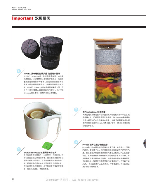
18
KUVRD发布通用型镜头盖 免受雨水侵蚀
1
disposable-bag 创意陶瓷杯茶包夹
2
Ploota 世界上最小的救生衣
Ploota是一款内置传感器的游泳安全工具,外形是一个项圈的造型,套在脖子上。
其内置有利用二氧化碳充气的安全气囊。
其原理和汽车副驾驶的安全气囊有点相似。
Ploota是智能的,当传感器检测到佩戴者头部已经处于水下30秒钟,将自动触发安全气囊的充气膨胀,将佩戴者头部始终保持垂直于水面以上。
如果使用者感觉自己快要溺水了,也可以手动启动。
你可以戴着Ploota去游泳、浮潜或潜水,它可以保证更多的生命得到拯救。
用Picklestone 制作泡菜
传统的泡菜制作需要一个沉重的石头给泡制对象一个压力,然而容器太大,已经不适合现代的厨房。
Picklestone便携罐使任何人都可以把它放在家庭冰箱里。
将剩下的蔬菜削成你喜欢的形状加上盐水,用石头和木头盖子密封,就可以制作完成好吃的零食了。
Copyright©博看网 . All Rights Reserved.
图表
WORLD VISION 2018.NO.5
垂直、水平方向轴,使它可以指向任何方向。
金属手臂
杆可以与方形相机脱离,使用方便。
相机自带声音及运动检测,捕获1080p高清图像,可以通过云储存在你的
手机上播放。
其小巧优雅的外形可以被放置在任何地方。
Copyright©博看网 . All Rights Reserved.。
DIN EN ISO 20567-2

DIN EN ISO 1513
ISO 1514
DIN EN ISO 1514
ISO 2808
DIN EN ISO 2808
ISO 3270
DIN EN 23270
ISO 15528 DIN EN ISO 15528
Amendments This standard differs from DIN 55996-2:2002-08 as follows: a) ISO 20567-2:2005 has been adopted without any modifications. b) The DIN number has been changed to DIN EN ISO 20567-2. c) The standard has been editorially revised. No technical changes have been made.
The DIN Standards corresponding to the International Standards referred to in this document are as follows:
IEC 60454-2 DIN EN 60454-2 (VDE 0340-2)
ISO 1513
The responsible German body involved in its preparation was the Normenausschuss Beschichtungsstoffe und Beschichtungen (Coatings and Coating Materials Standards Committee), Technical Committee NAB 7 Allgemeine Prüfverfahren für Beschichtungsstoffe und Beschichtungen.
造纸相关Tappi标准
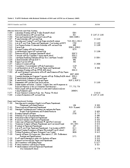
Table I. TAPPI Methods with Related Methods of ISO and ASTM (as of January 2005)TAPPI Number and Title ISO ASTM Fibrous Materials and Pulp TestingT 200 Laboratory Beating of Pulp (Valley Beater Method) 5264T 204 Solvent Extractives of Wood and Pulp 624 D 1107, D 1108 T 205 Forming Handsheets for Physical Tests of Pulp 5263, 5269/1T 207 Water Solubility of Wood and Pulp D 1110T 210 Sampling and Testing Wood Pulp Shipments for Moisture 7213, 801/1, 801/2T 211 Ash in Wood, Pulp, Paper, and Paperboard: Combustion at 525ºC 1762 D 1102T 212 One Percent Sodium Hydroxide Solubility of Wood and Pulp 699 D 1109T 213 Dirt in Pulp 5350/1, 5350/2T 220 Physical Testing of Pulp Handsheets 5270T 222 Acid-Insoluble Lignin in Wood and Pulp D 1106T 227 Freeness of Pulp (Canadian Standard Method) 5267/2T 230 Viscosity of Pulp (Capillary Viscometer Method) 5351/1T 231 Zero-Span Breaking Strength of Pulp (Dry Zero-Span Tensile) 15361 D 5804T 235 Alkali Solubility of Pulp at 25ºC 692T 236 Kappa Number of Pulp 302T 237 Carboxyl Content of Pulp D 1926T 240 Consistency (Concentration) of Pulp Suspensions 4119T 244 Acid-Insoluble Ash in Wood, Pulp, Paper, and Paperboard 776 D 586T 248 Laboratory Beating of Pulp (PFI Mill Method) 5264/2T 252 pH and Electrical Conductivity of Hot Water Extracts of Pulp, Paper,and Paperboard 6587, 6588T 254 Cupriethylenediamine Disperse Viscosity of Pulp (Falling Ball Method) 5351/1T 255 Water-Soluble Sulfates in Pulp and Paper 9198T 256 Water-Soluble Chlorides in Pulp and Paper 9197/1, 9197/2T 264 Preparation of Wood for Chemical Analysis D 1105T 266 Determination of Sodium, Calcium, Copper, Iron, and Manganese inPulp and Paper by Atomic Absorption Spectroscopy 777, 778, 779T 271 Fiber Length of Pulp and Paper by Automated Optical AnalyzerUsing Polarized Light 16065-1T 277 Macro Stickies Content in Pulp: the “Pickup“ Method D 6148T 280 Acetone Extractives of Wood and Pulp D 1107, D 1108 Paper and Paperboard TestingT 400 Sampling and Accepting a Single Lot of Paper, Paperboard,Fiberboard, or Related Product 186 D 585T 401 Fiber Analysis of Paper and Paperboard 9184 (5 parts) D 1030T 402 Standard Conditioning and Testing Atmospheres for Paper,Board, Pulp Handsheets, and Related Products 187 D 685T 403 Bursting Strength of Paper 2758 D 774T 405 Petroleum Wax in Impregnated Papers D 590T 406 Reducible Sulfur in Paper and Paperboard D 984T 409 Machine Direction of Paper and Paperboard D 528T 410 Grammage of Paper and Paperboard (Weight Per Unit Area) 536 D 646T 411 Thickness (Caliper) of Paper, Paperboard, and Combined Board 534, 3034 D 645T 412 Moisture in Paper and Paperboard 287 D 644T 413 Ash in Wood, Pulp, Paper and Paperboard: Combustion at 900ºC 2144 D 586T 414 Internal Tearing Resistance of Paper (Elmendorf-Type Method) 1974 D 689T 423 Folding Endurance of Paper (Schopper Type Tester) 5626 D 643T 425 Opacity of Paper (15/d geometry, Illuminant A/2º, 89% ReflectanceBacking and Paper Backing) 2471 D 589T 428 Hot Water Extractable Acidity or Alkalinity of Paper D 548T 430 Copper Number of Pulp, Paper, and Paperboard D 919T 431 Ink Absorbency of Blotting Paper D 2177T 432 Water Absorbency of Bibulous Papers D 824T 433 Water Resistance of Sized Paper and Paperboard(Dry Indicator Method) D 779T 435 Hydrogen Ion Concentration (pH) of Paper Extracts(Hot Extraction Method) 6588 D 778T 437 Dirt in Paper and Paperboard D 2019 T 438 Zinc and Cadmium in Paper D 1224 T 441 Water Absorptiveness of Sized (Non-bibulous) Paper, Paperboard,and Corrugated Fiberboard (Cobb Test) 535 D 3285 T 444 Silver Tarnishing by Paper and Paperboard D 2043 T 448 Water Vapor Transmission Rate of Paper and Paperboardat 23ºC and 50% RH 2528 E 96, E 398 T 449 Bacteriological Examination of Paper and Paperboard 8784/1T 452 Brightness of Pulp, Paper, and Paperboard (DirectionalReflectance at 457 nm) 2469,2470 D 985T 453 Effect of Dry Heat on Properties of Paper and Board 5630/1 D 776T 454 Turpentine Test for Voids in Glassine and Greaseproof Papers5634T 455 Identification of Wire Side of Paper D 5039 T 456 Wet Tensile Breaking Strength of Paper and Paperboard(“Wet Tensile Strength”) D 829T 458 Surface Wettability of Paper (Angle of Contact Method) D 724T 459 Surface Strength of Paper (Wax Pick Test) D 2482 T 460 Air Resistance of Paper (Gurley Method) D 726T 461 Flame Resistance of Treated Paper and Paperboard D 777T 462 Castor-Oil Penetration Test for Paper D 780T 464 Water Vapor Transmission Rate of Paper and Paperboard atHigh Temperature and Humidity 2528 E 96, E 398 T 465 Static Creasing of Paper for Water Vapor Transmission Tests 2528T 479 Smoothness of Paper (Bekk Method) 5627T 480 Specular Gloss of Paper and Paperboard at 75 Degrees 8254-1 D 1223 T 487 Fungus Resistance of Paper and Paperboard D 2020 T 489 Bending Resistance (Stiffness) of Paper and Paperboard(Taber-type Tester in Basic Configuration) 2493 D 5342 T 491 Water Immersion Test of Paperboard 5637T 494 Tensile Properties of Paper and Paperboard (Using ConstantRate of Elongation Apparatus) 1924/2 D 828T 500 Book Bulk and Bulking Number of Paper D 2175 T 507 Grease Resistance of Flexible Packaging Materials 5634 F 119T 509 Hydrogen Ion Concentration (pH) of Paper Extracts (ColdExtraction Method) 6588 D 778T 511 Folding Endurance of Paper (MIT Tester) 5626 D 2176 T 519 Diffuse Opacity of Paper (d/0 paper backing) 2471T 523 Dynamic Measurement of Water Vapor Transfer ThroughSheet Materials E 96, F 372 T 525 Diffuse Brightness of Pulp (d/0) 2469, 3688T 536 Resistance of Paper to Passage of Air (High Pressure Gurley Method) D 726T 538 Smoothness of Paper and Paperboard (Sheffield Method) 8791/3T 543 Bending Resistance of Paper (Gurley-Type Tester) 5628 D 6125 T 544 Effect of Moist Heat on Properties of Paper and Board 5630/3 D 4714 T 547 Air Permeance of Paper and Paperboard (Sheffield Method)5636-4T 549 Coefficients of Static and Kinetic Friction of Uncoated Writingand Printing Paper by Use of the Horizontal Plane Method 15359 D 4917T 550 Determination of Equilibrium Moisture in Pulp, Paper andPaperboard for Chemical Analysis 287 D 644T 553 Alkalinity of Paper as Calcium Carbonate (Alkaline Reserve of Paper) D 4988 T 555 Roughness of Paper and Paperboard (Print-Surf Method) 8791/4T 559 Grease Resistance Test for Paper and Paperboard D 722T 560 CIE Whiteness and Tint of Paper and Paperboard (Using d/0?,Diffuse Illumination and Normal Viewing) E 313 T 560 currently withdrawn but may be reinstatedT 562 CIE Whiteness and Tint of Paper and Paperboard (Using 45?/0?Directional Illumination and Normal Viewing) E 313 T 562 currently withdrawn but may be reinstatedT 563 Equivalent Black Area (EBA) and Count of Visible Dirt in Pulp,Paper and Paperboard by Image Analysis D 6101 T 564 Transparent Chart for the Estimation of Defect Size 5350/3T 566 Bending Resistance (Stiffness) of Paper (Taber-type Tester in0 to 10 Taber Stiffness Unit Configuration) 2493 D 5650T 570 Resistance to Mechanical Penetration of Sanitary Tissue Paper(Ball Burst Procedure) D 6548 T 571 Diffuse Brightness of Paper and Paperboard (d/0)2469, 2470T 572 Accelerated Pollutant Aging of Printing and Writing Paperby Pollution Chamber Exposure Apparatus D 6833 T 573 Accelerated Temperature Aging of Printing and Writing Paperby Dry Oven Exposure Apparatus D 6819 Nonfibrous Materials TestingT 600 Analysis of Formaldehyde in Aqueous Solutions of FreeFormaldehyde in Resins D 2194 T 602 Analysis of Sulfuric Acid E 223 T 605 Reducing a Gross Sample of Granular or Aggregate Materialto Testing Size C 702T 607 Analysis of Casein D 4689 T 610 Preparation of Indicators and Standard Solutions E 200 T 613 Analysis of Caustic Soda E 291 T 617 Analysis of Lime C 25 T 618 Analysis of Limestone C 25 T 653 Specular Gloss of Paper and Paperboard at 20º D 523 T 657 Sampling of Fillers and Pigments C 322 T 665 Analysis of Talc D 717 T 689 Analysis of Crude Tall Oil D 803 T 698 Determination of Wetting Tension of Polyethylene and PolypropyleneFilms and Coatings (Modified Visking Analytical Technique) D 2578 Container TestingT 801 Impact Resistance of Fiberboard Shipping Containers D 880 T 802 Drop Test for Fiberboard Shipping Containers D 5276 T 803 Puncture Test of Container Board 3036T 804 Compression Test of Fiberboard Shipping Containers D 642 T 807 Bursting Strength of Paperboard and Linerboard 2759T 808 Flat Crush Test of Corrugated Board (Flexible Beam Method) 3035T 809 Flat Crush of Corrugated Medium (CMT Test) 7263T 810 Bursting Strength of Corrugated and Solid Fiberboard2759T 811 Edgewise Compressive Strength of Corrugated Fiberboard(Short Column Test) 3037T 815 Coefficient of Static Friction (Slide Angle) of Packaging andPackaging Materials (Including Shipping Sack Papers,Corrugated and Solid Fiberboard) (Inclined Plane Method) D 4918 T 825 Flat Crush Test of Corrugated Board (Rigid Support Method) 3035T 826 Short Span Compressive Strength of Paperboard 9895T 838 Edge Crush Test Using Neckdown 3037T 839 Edgewise Compressive Strength of Corrugated Fiberboard UsingThe Clamp Method (Short Column Test) 3037Structural Materials TestingNoneTesting PracticesT 1200 Interlaboratory Evaluation of Test Methods to DetermineTAPPI Repeatability and Reproducibility D 1749 T 1205 Dealing with Suspect (Outlying) Test Determinations E 178 T 1210 Units of Measurement and Conversion Factors D 4826。
AutoChem1 II 2920

TPR 程序升温还原 TPO 程序升温氧化 脉冲化学吸附 BET比表面
和程序升温技术。人工操作的 步骤很少,绝大部分操作由软 件精确控制。
自动化的步骤由操作者创立的 样品文件控制,除了样品本身 的信息外,样品文件列出全部 特定指令的清单,仪器完全按 照清单上的指令执行操作。在 连续的温度和气流控制中,仪 器监控每一步操作并初始化下 一步操作。 由于每一步操作的 初始化不需要人为介入,延迟 被消除。人工操作带来的误差 减少,同时人力得到节省。用 户可以创建分析条件的标准测 试文件,其他重复样品测试可 以套用。
高灵敏度和稳定性的热导池探测气流中的浓度变化
,
金属氧化物程序升温还原
样品预制
H2 负载气
金属还原为基态
氧气· 脉冲进入
He负载气
或者
He负载气
氧气连续气流
探测器得到氧 气的消耗量
脉冲化学吸附
脉冲化学吸附确定活性表面积、金属分散度和活性颗粒 尺寸。 每一次脉冲注入的反应气体量由loop环体积全自动提供 ,三种体积的loop环可供选择。
BET比表面分析
BET比表面可以评估催化剂在化学吸附前后的总比表面的 变化,并研究孔填充和材料烧结等现象。
样品分析条件
可插入99步实 验步骤
Close
样品报告选项
Close
预设气体的质量流量计参数文件
预设的活性金属参数文件
三种热电偶放置方式
1.热电偶放 在样品管内 部
炉子热电偶
3.热电偶带有石英罩 保护放置在样品管内
2. 使用夹子 固定热电偶 放置在样品 管外面
方便的Windows界面
创建样品文件
2920 催化剂表征系统提供精确程序 升温技术进行催化剂性质的表征,如 金属分散度、活性金属表面积、酸性 强度等。 软件基于Windows提供熟悉、易操作 的用户界面和数据处理,用户制订的 高度灵活分析步骤可以进行最复杂的 预处理和分析过程,包括TPD、TPR 、TPO、 TPRx和脉冲化学吸附。 另外,2920可以作为一台微反应器 。 可进行单点BET比表面测试
- 1、下载文档前请自行甄别文档内容的完整性,平台不提供额外的编辑、内容补充、找答案等附加服务。
- 2、"仅部分预览"的文档,不可在线预览部分如存在完整性等问题,可反馈申请退款(可完整预览的文档不适用该条件!)。
- 3、如文档侵犯您的权益,请联系客服反馈,我们会尽快为您处理(人工客服工作时间:9:00-18:30)。
Ø投影面的垂直面
只垂直于一个投影面、但倾斜于另两个投影面
1. 铅垂面:
Z
Z
V
p
p
p
H: 铅垂面 V :正垂面 W:侧垂面
p
P X
p
X
O
YW
p
Y
YH
55
第三节 平 面 的 投 影
Ø投影面的垂直面
2. 正垂面
r
X
Z
r
O
r
3. 侧垂面
q
YW
X
q
Z
q
O
YW
YH
YH
投影特性:1.平面在它所垂直的投影面上的投影积聚成直线,该直线 与投影轴的夹角反映空间平面与相应投影面的倾角 ;
a f
b
X
a
Z
a f
b
O
YW
f b
YH
F点不在AB直线上
注:侧平线应通过第三投影求解
33
第二节 直线的投影
Ø直线上的点———定比性
一直线上两线段长度之比,等于它们的投影长度之比。
Z
V
c a
b B
C
b c
c a
X
X
A
a
cb
c
a
Z
b
b
c
a
O
YW
b
Ya
AC:CB=ac:cb= ac: cb= ac: cb
d
c
X
a c
k
b
O d
k
b
49
【例21】过点A作一条直线AB与已知直线CD相交,交点距V面20mm。
a
k
d
c
b
X
O
a
d
k
c
b
50
第三节 平 面 的 投 影
Ø平面的表示方法
a
c a
* c a c a c
a
c
b
X
b
d b
b d
b
O
a
ca
ca
c ac
a
c
b
bd b
d b
b
不在同一直 线上的三点
一直线和 线外一点
9
第一节 点的投影
Ø点的投影与直角坐标的关系
投影面→坐标面 投影轴→坐标轴 轴的交点O→坐标原点
距离的关系:
X
Aa=Xa Aa =Ya Aa =Za
投影 坐标 立体图
Z
a
A
a
z x
O
y
a
Y
10
第一节 点的投影
Z
V
a(x, z)
aZ
y
A(x,y,z)
a (y, z)
W
aX X
x
O
z
aY a (x, y) H
Ø投影面的垂直线
垂直于某一个投影面
1. 铅垂线:
Z
H: 铅垂线 V: 正垂线 W: 侧垂线
V
a'
A
b'
X
B
a(b)
Z
a
a"
b
X
O
b"
a(b)
YH
Y
a b
YW
28
第二节
Ø投影面的垂直线
2. 正垂线:
Z
c(d )
d c
直线的投影
3. 侧垂线:
e
f Z e(f X
O
YW
c
YH 投影面垂直线的投影特性:
e
f
YH
1.直线在其所垂直的投影面上的投影积聚成一点;
2.直线在其它两投影面上的投影反映实长且垂直于相应的投影轴。
29
【例8】试判断下列直线对投影面的相对位置。
a
b
X
O
a
b
侧平线
c
d
Z
X
O
(e) f e f
O
c
d
侧垂线
正垂线
30
【例9】试判断下列直线对投影面的相对位置。
a b
c
d
Z
e
e
X
O
X
O
a
Y
a(x, z) X
a (x, y)
直观图
Z a (y, z)
O Yw
YH 投影图
11
【例2】已知A点的立体图,作出其三面投影图。
Z
a
aZ
A
X aX
a
O
a
aY
Y
a
aX X
a
aZ Z
a
O aY YW
aY YH
(a)直观图
(b)投影图
12
【例3】已知 A(35,10,25),作出其三面投影图。
a
X 35 a
2.其余两投影均为平面的类似形,面积缩小。
56
第三节 平 面 的 投 影
Ø投影面的平行面
‖ H :水平面 平行于某一个投影面的平面 ‖ V :正平面
‖ W:侧平面
1. 水平面:
V
p
X
Z
p
P
p
X
Z
p
O
p
p Y
YH
YW
57
第三节 平 面 的 投 影
Ø投影面的平行面
2. 正平面:
q
Z
q
3. 侧平面:
Z
O
c
cd
Y
YH
d
c
YW
26
第二节 直线的投影
3. 侧平线:
Z
V
e
e E
f
X
F
e
e
f
X
e
f
f
f
平行线的投影特性:
Y
Z
e
f
YW
YH
1 .直线在其所平行的投影面上的投影反映实长,该投影与投
影轴的夹角反映了空间直线与其它两个投影面的倾角;
2 .其它两投影长度缩短,且分别平行于相应的投影轴。
27
第二节 直线的投影
第二节 直线的投影
Ø投影面的平行线
平行于一个投影面、倾斜于另两个投影面 1. 水平线:
‖ H :水平线 ‖ V :正平线 ‖ W:侧平线
Z
V
Z
a b a b
a b
A
a
X
B b
O
YW
X
a
a b
b
YH
Y
25
第二节 直线的投影
Ø投影面的平行线
2. 正平线:
V
c X
Z d
D
C
c
d
Z
d
d
c
X
b
c d
f
f
O
正平线
水平线
铅垂线
31
第二节 直线的投影
Ø直线上的点———从属性
若点在直线上,则点的投影在直线的各同名投影上。
Z
V
c a
b B
C
b
c
a
c X
X
A
a
b
c
ac
a
Y
Z
b
b
c
a
O
YW
b
YH
32
【例10】判断 E、F点是否在直线AB上。
f b e a
X
O
a e
f b
E点在AB直线上 F点不在AB直线上
YH
34
【例11】试判断K点是否在直线EF上。
e k
f
X
e
k f
V
e k f
O
X
Z
E K
F e
k f
直接判断:K点不在直线EF上
e k f
Y
35
【例12】判断K点是否在直线上。
1
k
2
X
O
1
k
用定比性作图:
k
K点不在直线上
2
36
【例13】已知K点在直线AB上,试求作K点的H面投影。
a
k
b
X
O
a
k b
Ø平面上的直线
C K
c k
B
X
HA
特性一: 若直线上的两点在平面上, 则直线在平面上。
b
b k
h a O
ha
c
62
第三节 平 面 的 投 影
Ø平面上的直线
A
c
E
B 特性二:
F
X b e
C
e b
若直线上的一点在平面上,
c
并且平行于平面上的任一条
直线,则直线在平面上。
f a O
a
f
63
第三节 平 面 的 投 影
Z
25
a
o
10
YH
10mm
YW
13
【例4】已知A、B、C 三点的投影图,作出其立体图,并判别
各点的空间位置。
Z
Z
c a
c a
X b
c
b YW
a
b
YH
C c c
a A
a
b
X
O
c a bB
b
Y
A 位于 空间
B位于 H面 C位于 V面
14
【例5】已知A、C 两点的投影图,作出其立体图,并
判别各点的空间位置。
两相交 直线
两平行 直线
任意平 面图形
51
第三节 平 面 的 投 影
Ø平面的投影图
c Z c
p
a