RS_250燃气调压阀
各种燃气阀门的介绍 -

各种燃气阀门的介绍建设部十分重视对燃气阀门的规范性建设,燃气阀门的行业标准有CJ3005-1992《城镇燃气用灰铸铁阀门的通用技术要求》、CJ3055-1995《城镇燃气用阀门的试验与检验》、CJ3056--1995《城镇燃气用球墨铸铁和铸钢制阀门的通用技术条件》、2002年6月又通过了《家用手动燃气阀门》的行业标准。
这些标准的制订和颁布规范了阀门行业、推动了燃气阀门的进步和发展、促进了燃气事业的发展;为研制、生产、使用单位提供了参考依据;提高了对燃气阀门与通用阀门区别的认识,保证了燃气阀门的安全裕度;受到了燃气同行们的欢迎一、RX系列油密封式旋塞阀上世纪八十年代,我国燃气主要是人工煤制气,蝶阀人工煤制气中有较多的杂质和"煤气胶",原来传统使用的单闸板契式水闸阀越来越不能适应燃气工况的需要,这类阀门普遍存在"关不严"和阀杆咬死的问题,我们参考日本技术研制而成的RX系列燃气用油密封式旋塞阀,解决了关不严和阀杆咬死的问题二、RZ系列燃气用平行双闸板闸阀随着燃气事业的发展和煤气厂的纷纷建立,需要较大甚至特大公称通径的燃气专用阀门,RZ系列燃气用平行双闸板闸阀针对人工煤气形成的问题给予一一解决,最大通径达1600mm1、平行双闸板闸阀在启闭过程中能刮去密封面上的"煤气胶",解决了煤气杂质黏附在密封面上影响阀门密封的大问题2、装有阀杆保护套,使阀杆不受"煤气胶"的侵蚀3、阀门下部带有排污孔侧盖,可以清扫落在阀腔底部的垃圾4、全通径设计流阻小,又能通清管器5、阀体采用特殊设计的"鼠笼框架式加强筋"减轻了阀门总体重量,增强了壳体强度和刚度6、RZ系列燃气闸阀壳体选用灰铸铁制造,价格低廉;第七、该系列闸阀带有全封闭的启闭指示器,使操作者清楚了解阀门所处状态三、RQZ系列球墨铸铁制燃气用平行双闸板闸阀随着我国天然气进入城镇,笔者与上海煤气总公司、苏州市燃气设备阀门制造有限公司根据天然气的特点又研制了RQZ球墨铸铁制燃气用平行双闸板闸阀,该闸阀除保留了RZ系列闸阀的特点外,选用的材质增强了阀门的耐磨性,同时将压力等级提高到了高压B级四、蝶阀蝶阀相比上述几种阀门轻便,口径大,价格较低,八十年代初期部分煤气公司曾-度采用蝶阀,经过十年左右的使用,普遍认为效果不好。
HORA气动调节阀样本

阀芯 根据实际工况HORA为用户提供最专业的阀芯。 在大关断压力工况下HORA对阀芯进行平衡阀室 设计,使阀门工作更稳定,寿命更长
密封类型 根据不同介质及温度选择密封材料
3
类型
阀体材质
黄铜 Rg-5 CC491K
铸铁 GG25 EN-JL1040 球铁 GGG-40.3 EN-JS1024 铸钢 GS-C25N 1.0619+N
产品优点 ● 多种阀门型号辅以不同类型的辅件,针对不同工况
可以为用户提供最佳的解决方案 ● 阀门口径DN15-DN800,可为用户提供完整的调节
阀产品系列 ● 同一规格的阀门均提供4种以上的KVs值供用户选
择,提高现场工况的适应性和灵活性 ● 阀门长行程设计,以实现更佳的调节精度 ● 执行机构气开,气关操作方式可灵活选择 ● 执行机构弹簧与膜片有效寿命200百万次,同时没
历经40多年的发展,来自德国北威州Schloß Holte-Stukenbrock的家族企业—HORA公司与世界上著名 的电站设备制造商,能源供应商以及测量-,自动化控制企业建立了良好的伙伴关系。在全世界阀门市 场中HORA品牌以创新,可靠,及卓越的性能得到了广泛的认可。
2008年HORA是德国4家最佳制造商 大 奖M X - A w a r d ( M a n u f a c t u r i n g Excellence Awar)获得者之一
压缩空气
HORA 气动 调节阀
压力调节并联设计
压缩空气
压缩空气
HORA 气动 调节阀
HORA 气动 调节阀
压力调节串联设计
压缩空气
HORA 气动 调节阀
9
压缩空气
燃气调压装置使用说明书
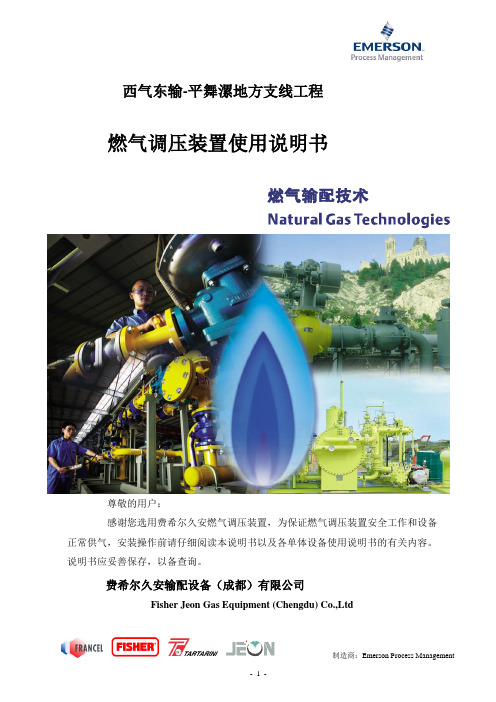
西气东输-平舞漯地方支线工程燃气调压装置使用说明书尊敬的用户:感谢您选用费希尔久安燃气调压装置,为保证燃气调压装置安全工作和设备正常供气,安装操作前请仔细阅读本说明书以及各单体设备使用说明书的有关内容。
说明书应妥善保存,以备查询。
费希尔久安输配设备(成都)有限公司Fisher Jeon Gas Equipment (Chengdu) Co.,Ltd目录1概述 (3)2主要参数 (4)2.1各站主要参数 (4)2.2型号说明 (5)3燃气调压装置的安装程序 (6)4燃气调压装置的运行与调试 (7)4.1空气置换 (7)4.2运行前的准备及注意事项 (8)4.3气密性试验 (9)4.4调试运行程序 (10)4.5调压器参数设定 (12)4.6工作管路与备用管路的人工切换方法 (14)4.7停机的操作程序 (15)5常见故障分析与排除 (16)6燃气调压装置的维修保养 (18)6.1检修周期及维修程序 (19)6.2维护保养中的注意事项 (21)7尺寸,重量及吊装 (22)7.1设备尺寸及重量 (22)7.2设备吊装 (22)8售后服务 (23)1概述(燃气调压装置是在城镇燃气输配系统中,专为城市门站、分输站、储配站、燃气轮机、燃气锅炉、燃气发电厂或其他大型专用用户设计的成套调压设备。
通常具有接收气源来气、燃气净化、燃气调压、气量分配、计量、安全保护等功能;采用整体橇装形式,所有功能模块集成于一个或多个撬座上。
根据工程条件和系统需要,还可增设消音设备、加热设备、监控及数据采集设备、加臭装置、清管设备等功能模块。
具有安全性好、可靠性高、经济性能良好、占地面积小、内部结构优化合理、安装调试简单、测试维修方便等特点。
本燃气调压装置按照我国现行国家标准GB50028《城镇燃气设计规范》及我公司企业标准Q/76227017-0.1-2006《撬装式城镇燃气调压装置》执行。
)本说明书主要介绍燃气调压装置的主要参数、结构特点、主要设备、安装运行调试方法、故障处理、维修保养等内容。
燃气切断阀资料
RTZ-*/0.4Q系列调压器
5 维护与故障排除 5. 维护 1 定期检查:建议以3~6个月为一周期由专业维修人 员对调压器进行定期维修保养。 检查关闭压力:打开调压箱门,缓慢关闭出口 阀门,在测压开关处接上测压压力计,打开测压开 关读出关闭压力值(至1分钟读第一次,到3分钟时 读第二次),若关闭压力为正常值可不拆修调压器。 2 保养 根据燃气净化程度,合理安排维修周期,清除 调压器内污物,特别注意过滤器、阀口等处应清洗 干净,及时更换密封垫、皮膜、O型圈等易损件。 维修时应检查各零部件是否完好无损,然后才能进 行组装,组装后应保证各部件灵活动作。维修安装 完毕,用肥皂水检查所有连接密封部位是否渗漏。 维修后应重新设定进出口压力,放散压力和切断压 力。
更换膜片; 更换密封垫片。
调压器不工作 调压器震动
切断阀复位; 更换主皮膜。
流量过低,介质水分含量过高。排除水分。
人有了知识,就会具备各种分析能力, 明辨是非的能力。 所以我们要勤恳读书,广泛阅读, 古人说“书中自有黄金屋。 ”通过阅读科技书籍,我们能丰富知识, 培养逻辑思维能力; 通过阅读文学作品,我们能提高文学鉴赏水平, 培养文学情趣; 通过阅读报刊,我们能增长见识,扩大自己的知识面。 有许多书籍还能培养我们的道德情操, 给我们巨大的精神力量, 鼓舞我们前进。
• 超高压紧急切断阀的复位开启(普通型) 1 关闭监控处下游阀门和信号管处的截止阀1,开启检 测口截止阀2,待监控器内气体排空后将其关闭。 2打开机构盒盖,盒子右上部有一红色复位杆(K), 将其推向右上方,使机构中杠杆(L)扣上。 3取下机构盒左下角四方工具(C)套在复位装置(M) 的四方轴上,顺时钟转动四方轴使限位钩与杠杆(J)扣 上。 4将工具放回原处,盖上盒盖,至此机构复位完成。 5排除故障,确认监控处压力正常后,缓慢开启信号管 处的截止阀1,切断阀即可投入正常运行。
燃气调燃调压箱选型书书;.pdf
成燃成都华 燃气调(编制:审批:华泰燃 2调压箱(试行燃气设备2019.3选型书)备有限3.4书限公司司123稳关 概述Q 系及小型直燃重量轻,压维护简便。
油气等无腐镇燃气调压 2 功能2.1 基本功2.2 可选保 技术参数规格通径 进口出口压力范围进口 出口工作温度稳压精度等级关闭压力等级切断压力放散压力过滤精度/μ系列燃气箱适燃设备调压。
压力稳定,关。
适用介质,腐蚀性气体。
压箱》标准。
功能:调压、保温、伴热等 数口/mm 口/mm /MPa 口/KPa 度/℃ 级AC 级SG力 力 mm适用于宿舍单。
一体化结构关闭灵敏,活天然气、人。
产品符合G 。
过滤、切断等功能。
QX(N)225252 ~ 1Q 系列燃元、庭院、楼构设计 ,体积活法兰结构,人工煤气、液GB27791‐201 断、安全放散 表25/255 5100 标燃气调压楼栋积小, 操作 液化石 11《城 散功能。
1 技术参Q标配默认:5压箱数QX(N)40/4040 40 0.05~0.42 ~ 100 ‐20 ~ 60 最高达AC5最高达SG10按实际设定按实际设定50 选 图0 配:5、 10、1 Q 系列QX(N)550502 ~ 1 2050/500 0100表注:1+1结构采用旁通调压器时,出口压力为2‐4kpa 。
4 流量表2 流量规格 出口压力/KPa进口压力/MPa0.05 0.1 0.2 0.3 0.4QX(N)25/252 23 34 60 65 70 5 24 35 60 65 71 10 24 35 60 65 71 15 24 35 60 65 71 30 24 35 60 65 71 50 - 35 60 70 80 100 - - 70 75 85QX(N)40/402 27 40 91 98 101 5 28 50 106 110 120 10 28 50 106 110 120 15 28 50 106 110 120 30 28 50 106 110 120 50 - 50 70 80 90 100 - - 90 110 120QX(N)50/502 36 45 120 122 124 5 40 60 120 126 130 10 40 60 120 126 130 15 30 60 120 126 130 30 30 60 120 126 126 50 - 60 80 90 100 100 - - 120 130 140表注: 流量是标准状态下、天然气相对密度为0.6时的流量,单位Nm3/h1 2 3表注概述A 系键设备,主区、公共用天然气、液产品集成化统性能稳定品符合GB功能2.1 基本2.2 可选 技术参数注:旁通采用规格通径 进口出口压力范围进口 出口工作温度稳压精度等关闭压力等切断压放散压过滤精度/系列调压箱(主要起到调压用户、中小型液化石油气、化设计,具有定可靠、功能B27791‐2011本功能:调压选计量、保温 数 用调压器时,口/mm 口/mm 口/MPa 口/KPa 度/℃ 等级AC 等级SG力 力 μmm柜)是燃气输压和稳压作用型直燃设备等、人工煤气等有结构紧凑、能完善、安装《城镇燃气调、过滤、切断、伴热等功能 出口压力为AX(N)5050 502 ~ 10A 系列输配系统中的用,适用于居等供气,适用等无腐蚀性气占地面积小装方便等优点调压箱》标准断、安全放散能。
煤层气公司燃气调压器及配套切断阀技术要求

煤层气公司燃气调压器及配套切断阀技术要求
一、燃气调压器型号:RTJ—150/1.6ZA/RZ110A 进口压力:0.2~0.4MPa
出口调节压力:3~50KPa 调压精度δP2:≤±10%
关闭压力Pb:≤1.25P2n 公称管径:DN150
公称压力:PN16(法兰连接)流量范围:3000~25000m3/h
该燃气调压器本体具备:大流通、高精度、反应快速灵敏等特点,可配置减噪装置。
二、燃气切断阀型号为:RQZ--1/150Z 公称通径:DN150
进口压力:0.2~0.4MPa 设定压力:5~50KPa
切断精度:±5% 反应时间≤1sec 工作温度:-20℃~60℃该燃气切断阀具备切断精度高,切断响应速度快,压力设定简单,操作方便等特点。
在出口压力超过预设的限定值时,切断阀自动切断气流,如需恢复时只能采取人为手动恢复。
供货方负责免费提供煤气安全调压管线,调压器调压取压管,切断阀切断取压管,煤气安全调压管线进、出口压力表,煤气安全调压管线考克,煤气安全调压管线FS-H-50型安全放散阀,(将所提供的产品在出厂前安装在煤气安全调压管线上)产品合格证、说明书等相关技术资料。
免费调试设备及培训现场操作人员。
质保期一年,因供货方产品质量问题,质保期内无偿维修或更换,由此而造成的损失亦由供方负责。
在正常使用过程中出现问题后,供货方技术人员24小时内赶到现场。
煤层气公司
2019-6-10。
潍柴燃气电控系统介绍02

排放
Full power operation point
NOx CO HC
Lean
Stoich
Rich
Fuel Equivalence Ratio
Slide 26
HC, CO 影响
过浓 -> HC,CO 增加 气缸积碳 -> HC 增加 失火-> HC 增加 机油消耗 ->HC 增加
Slide 27
31%
Slide 28
Woodward OH1.2
工作原理及控制系统
Slide 29
OH1.2控制系统
ECM 发动机电控模块 Harness 线束 Fueling 燃料控制 Air Control 进气控制 Ignition 点火控制 Engine timing/speed measurement 定时/转速 测量 Misc Peripherals 周边附件
设置
设置值在ECM长期断电后仍可保存在 EEProm 出厂设定
此设置不可擦除 ECM 的系列码为一例子
Field/EOL 设置
如果不同Prom/ID的新程序载入,此设置自动消除 例如燃料计量标定,速度调速限值和点火定时补偿
Slide 37
ECM 数据保存
故障码
保存在RAM中并且不可用钥匙开关擦除 此数据在ECM断电或 VBAT1 和 VBAT2 断开时被擦除
Slide 30
ECM (发动机控制单元)
ECM 是系统的大脑 ECM 是一敏感部件,应按照敏感电子器件的操作 规范操作
Slide 31
ECM
2 个连接接口 60 针 I/O 底盘固定式 12 ,24 V 系统兼容 可进行软件编程 Motorola HC12 微处理器
利雅路RS使用说明书
燃气燃烧器目录技术参数--------------------------------------------------------------------------------------------------------------------1 变型燃烧头-----------------------------------------------------------------------------------------------------------------1 L G P组件--------------------------------------------------------------------------------------------------------------------1 燃烧器描述-----------------------------------------------------------------------------------------------------------------2 包装-重量-----------------------------------------------------------------------------------------------------------------2 最大尺寸---------------------------------------------------------------------------------------------------------------------2标准附件---------------------------------------------------------------------------------------------------------------------2燃烧出力---------------------------------------------------------------------------------------------------------------------3测试锅炉---------------------------------------------------------------------------------------------------------------------3商用锅炉---------------------------------------------------------------------------------------------------------------------3燃气压力---------------------------------------------------------------------------------------------------------------------4安装--------------------------------------------------------------------------------------------------------------------------- 5 锅炉板------------------------------------------------------------------------------------------------------------------------ 5 燃烧头长度------------------------------------------------------------------------------------------------------------------5 燃烧器固定到锅炉上------------------------------------------------------------------------------------------------------5 设定燃烧头------------------------------------------------------------------------------------------------------------------6 阀门组------------------------------------------------------------------------------------------------------------------------7 电气系统--------------------------------------------------------------------------------------------------------------------8 点火前调整-----------------------------------------------------------------------------------------------------------------11 伺服电机------------------------------------------------------------------------------------------------11燃烧器起动-----------------------------------------------------------------------------------------------------------------11 燃烧器点火-----------------------------------------------------------------------------------------------------------------11 燃烧器校准-----------------------------------------------------------------------------------------------------------------12 1-点火输出功率----------------------------------------------------------------------------------------------------------12 2-最大输出功率-------------------------------------------------------------------------------------------------------12 3-最小输出功率------------------------------------------------------------------------------------------------------13 4-中间输出功率---------------------------------------------------------------------------------------------------------13 5-空气压力开关---------------------------------------------------------------------------------------------------------14 6-最大燃气压力开关--------------------------------------------------------------------------------------------------147-最低燃气压力开关--------------------------------------------------------------------------------------------------14 火焰有无检查------------------------------------------------------------------------------------------------------------14 燃烧器运行----------------------------------------------------------------------------------------------------------------15 最终检查------------------------------------------------------------------------------------------------------------------16 维护-------------------------------------------------------------------------------------------------------------------------1 6 状态/L E D面板-----------------------------------------------------------------------------------------------------------17 故障-可能的原因-排障建议-----------------------------------------------------------------------------------------18 本文中所提到的图形如下标识:1)(A)=图A的第1部分,与文本同页1)(A)p.4=图A的第1部分,页号4技术参数1) 参考条件:环境温度20℃,表压1000mbar,海拔100m2) 测试点16)(A)p.2处的压力,燃烧室压力为零,燃气环2)(B)p.7开启,燃烧器输出功率最大。
RS-34~190
30/90 ÷ 185
35/105 ÷ 215
12/35 ÷ 72 (01)
47/128÷229
55/149÷266
18/50÷89 (02)
Ph/Hz/V Ph/Hz/V
类型 kW kW IP kW A A IP V1 - V2 I1 - I2
3/50/230-400~(±10%)
(07) (08)
间歇式 (每 24小时至少停机一次)
(07) (08)
5,5 1
4,5 15,8 - 9,1 126 - 72,8
dBA
75
W
mg/kWh
mg/kWh
77
78,5
83.1
83
--
< 40
< 130
2009/142 - 2004/108 - 2006/95 - 2006/42 EN 676
CE 0085AP0944 CE 0085AP0945 CE 0085AP0946 in progress
1/50/230 ~ (±10%)
RMG
1,4
1,8
2,6
4
0,3
0,3
0,4
0,5
44
1,1
1,5
2,2
3,0
4,1 - 2,4
5,5 - 3,4
7,9 - 4,6
10,2 - 5,9
25 - 14,6
27,7 - 16
57,2 - 33,2
79 - 45,8
44
230V - 1x8 kV
1A - 20 mA
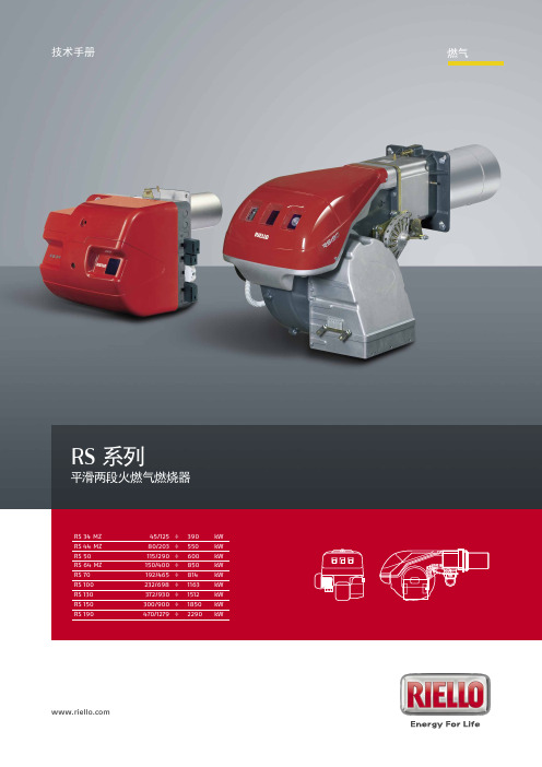
Two Stage Progressive Gas Burners RS Series RS 系列燃烧器的出力范围为 45-2290 kW,适用于中低温的热水锅炉、热风及蒸汽锅炉和导热油炉。 此系列燃烧器的运行模式为“平滑两段火”;燃烧器安装有微处理器控制面板,可显示运行状态及诊断故障原因。 风机和燃烧头性能的提升保证了燃烧器在全部出力范围内高效运行。 独特的设计保证了设备体积小巧,使用简单,维护方便。各类配件齐全,保证了工作的灵活性。
全气动注油机及其油脂泵设计说明书

2011届本科生毕业设计(论文)课题名称250全气动高压注油机及其油脂泵的设计专业机械设计制造及其自动化专业方向机电一体化班级07102112A1学号0710211217学生姓名陈业飞指导教师杨征瑞教研室机械电子上海应用技术学院机械与自动化工程学院250全气动高压注油机及其油脂泵的设计摘要:注油机主要运用于隧道、矿山、冶金,起重运输类的轴承及其他摩擦部位的润滑油加注。
目前大多数注油机的主要特点是手动或电动控制,效率均不高,且手动注油机劳动强度大,使用有局限性,出油压力不高。
国内对全气动高压注油机的研究较少,大多需要国外进口,价格昂贵。
本毕业设计的题目是气动注油机及控制系统的设计。
是为满足上海隧道工程的需要,为隧道工程机械润滑而设计的注油机。
设计正文气动注油机部分为总体方案选择、油脂泵的设计及控制实现方案、驱动气缸的设计三大部分注油机的设计在前期已经基本研究成功,已经投入生产。
但是,原来的注油机使用的是电控制,在隧道这种比较潮湿的环境中容易发生机器的故障及工作人员的人身安全问题。
所以,在原来的设计上加以改进,运用气动传动的优点,提高机器的适应性和可靠性。
气动注油机因以空气作为动力源,较易取得,用后的空气可直接排入大气中,处理方便,与液压相比不必设置回收油的油箱与管道,污染少,较能体现现在的环保概念。
有因空气的黏度很少,其损失也很小,所以便于集中供气,实远距离传送,这对于像隧道工程这样的地下操作是很方便的。
气压传动的环境适应性好,特别在易燃、易爆、多尘埃、强磁、辐射、振动严重的恶劣工作环境中,比如这次的隧道工程。
而且考虑到这次课题的设计要求,注油机的排量是:往复一次连续排油180ml,行程为120mm,注油压力为42 MPa,其注油量较高。
由于干油黏度很高,不易吸压,所以其工作频率不能很高,故综合考虑这些因素,本次设计的总体方案采用气动控制。
关键词:全气动注油机,高压,连续且流、排量可调The pneumatic high-pressure note oil 250mm design of themachineGeneral Information Design:Oiling machine is mainly used in tunnel, mining, metallurgy, materials handling classes and other friction bearing parts of the oil filling.Most current note oil machine main characteristic is a manual or electric control, efficiency are not high, and the manual labor intensity note oil machine, using has limitations, the oil pressure is not high. To the pneumatic high-pressure injection domestic oil feeder research less, mostly need foreign imports, the price is high.The graduation project is the subject of air oiling machine and control system design. Shanghai Tunnel Engineering is to meet the needs of lubrication for the tunnel project designed oiling machine.Design text pneumatic note oil machine parts for overall plan selection, grease pump design and control implementation scheme, driving cylinder design three sections.Pneumatic note oil machine for air as power supply, easily obtained, with the air after can be directly into the atmosphere, compared with convenient, handling of hydraulic oil tank not setting recovery less contamination with pipe, can reflect now, with the environmental protection concept. The viscosity for air, the loss is rarely facilitates concentration was small, so the supply, real long distance transmission, this for like tunnel project such an underground operation is very convenient. Pneumatic transmission good adaptability to the environment, especially in inflammable, explosive, dusty, strong magnetic, radiation, vibration serious odiously working environment, such as the tunnel project. And considering the topic design requirements, note oil machine emissions is: a continuous 180ml, reciprocating 120mm trip for the soot, note the oil pressure for 42 MPa, its note oil amount is higher. Because oil viscosity is very high, do not easy absorption of pressure, so its working frequency, it can high considering these factors, the design scheme of adopt pneumatic control.Keywords: all the pneumatic note oil machine, high pressure, flow, displacement is adjustable目录1 绪论 (1)1.1 研究目的及其意义 (1)1.2 注油机的分类 (1)1.3 发展趋势 (2)1.4 注油机的介绍 (2)1.4.1 手动液压注油机 (2)1.4.2 电动黄油注油机 (3)1.4.3 液压润滑脂注油机 (5)1.4.4 矿车轮注油机 (6)1.4.5 气动干油泵注油机 (9)1.5 总体分析 (13)2 油脂泵的设计 (15)2.1 总体方案的确定 (15)2.2 活塞杆的设计计算 (17)2.3 油脂泵缸筒壁厚的设计 (20)2.4 活塞的设计计算 (21)2.5 缸盖的连接螺栓的设计 (22)2.6 密封的设计 (23)2.7 增压盘的设计 (24)2.8 定压安全阀的设计 (25)3 气动控制系统的设计 (25)3.1 方案的比较及分析 (25)3.2 控制系统的方案确定 (27)4 驱动气缸的设计 (28)4.1 缸筒壁厚的设计 (28)4.2 活塞杆的设计 (29)4.2.1 活塞杆的初步选择 (30)4.2.2 活塞杆计算 (30)4.2.3 活塞杆强度校核 (30)4.3 耗气量的计算 (31)4.4 气缸进排气口直径的计算 (32)4.5 缸筒与缸盖的连接设计 (33)4.6 密封的设计 (33)5 升降气缸的设计 (36)5.1 缸筒内径的设计 (36)5.2 缸筒壁厚的设计 (38)5.3 活塞杆的设计 (39)5.3.1 初选活塞杆规格 (40)5.3.2 计算L/D (40)5.3.3 稳定性校核 (40)5.3.4 计算细长杆比 (40)5.3.5 确定系数m (41)5.3.6 校核活塞杆 (42)5.4 耗气量的计算 (42)5.5 气缸进排气口直径的计算 (43)5.6 密封的设计 (44)6 注油机总体设计 (48)7 设计小结 (50)8 特别致谢 (51)9 参考资料 (52)1 绪论1.1 研究目的及其意义注油机目前主要用于重型,矿山机械行业。
GASCAT-调压阀手册 ppt

工作监控式:即两台调压器中一台监控,另一台工作,但两台调压器取
压点相同,调压设定点也基本相近。 -
19
并联:两台调压器(调压路)入口与出口分别连接的方式。
工作备用切换式:即两台调压器中一台工作,另一台备用,两台调压器的取压 点相同,调压设定点也基本相近。
5、自用气撬的几点说明
-
15
1、系统工艺流程图
-
16
2、系统配置及原理
根据我国国家标准《输气管道工程设计规范》GB50251以及欧美 国家标准如《燃气输配系统中的调压站—功能要求》EN12186的 要求,燃气调压站、计量站中压力控制系统中的调压阀应优先选 用自力式调压阀,在流通能力方面宜采用流通能力较好的轴流式 调压阀。自力式调压器结构简单、维护方便,以广泛用于国内外 的压力控制系统。
调节原理:当出口用气量增加或入口压力降低时,燃气出口压力下降,造成皮膜上下压 力不平衡,此时皮膜下降,阀口开大,燃气流量增加,使压力恢复平衡状态。反之,当 出口用气量减少或入口压力增大,燃气出口压力升高,此时皮膜上升,使阀门关小,燃 气量减少,又逐渐使出口压力恢复至原来状态。
-
3
1、HORUS 系列轴流式调压阀
3、调压器的关闭特性,即当下游设备不用气或当调压器出口压力高于 设定压力时,调压器的阀口将关闭;
其中,调压器的关闭特性非常重要,它是调压器固有的性 质,关闭特性决定了调压器具有多种连接方式及工作特点。
-
18
2.2 调压器的串联与并联
串联:两台调压器按照从上游到下游的顺序依次连接的方式。
两级调压式:即两台调压器各自调压(取压点不同),比如系统入口压
利雅路RS使用说明书

燃气燃烧器RS70-100-130目录技术参数--------------------------------------------------------------------------------------------------------------------1变型燃烧头-----------------------------------------------------------------------------------------------------------------1 L G P组件--------------------------------------------------------------------------------------------------------------------1燃烧器描述-----------------------------------------------------------------------------------------------------------------2包装-重量-----------------------------------------------------------------------------------------------------------------2最大尺寸---------------------------------------------------------------------------------------------------------------------2标准附件---------------------------------------------------------------------------------------------------------------------2燃烧出力---------------------------------------------------------------------------------------------------------------------3测试锅炉---------------------------------------------------------------------------------------------------------------------3商用锅炉---------------------------------------------------------------------------------------------------------------------3燃气压力---------------------------------------------------------------------------------------------------------------------4安装---------------------------------------------------------------------------------------------------------------------------5锅炉板------------------------------------------------------------------------------------------------------------------------5燃烧头长度------------------------------------------------------------------------------------------------------------------5燃烧器固定到锅炉上------------------------------------------------------------------------------------------------------5设定燃烧头------------------------------------------------------------------------------------------------------------------6阀门组------------------------------------------------------------------------------------------------------------------------7电气系统--------------------------------------------------------------------------------------------------------------------8点火前调整-----------------------------------------------------------------------------------------------------------------11伺服电机------------------------------------------------------------------------------------------------11燃烧器起动-----------------------------------------------------------------------------------------------------------------11燃烧器点火-----------------------------------------------------------------------------------------------------------------11燃烧器校准-----------------------------------------------------------------------------------------------------------------12 1-点火输出功率----------------------------------------------------------------------------------------------------------12 2-最大输出功率-------------------------------------------------------------------------------------------------------12 3-最小输出功率------------------------------------------------------------------------------------------------------134-中间输出功率---------------------------------------------------------------------------------------------------------13 5-空气压力开关---------------------------------------------------------------------------------------------------------14 6-最大燃气压力开关--------------------------------------------------------------------------------------------------14 7-最低燃气压力开关--------------------------------------------------------------------------------------------------14火焰有无检查------------------------------------------------------------------------------------------------------------14燃烧器运行----------------------------------------------------------------------------------------------------------------15最终检查------------------------------------------------------------------------------------------------------------------16维护-------------------------------------------------------------------------------------------------------------------------16状态/L E D面板-----------------------------------------------------------------------------------------------------------17故障-可能的原因-排障建议-----------------------------------------------------------------------------------------18本文中所提到的图形如下标识:1)(A)=图A的第1部分,与文本同页1)(A)p.4=图A的第1部分,页号4技术参数2)测试点16)(A)p.2处的压力,燃烧室压力为零,燃气环2)(B)p.7开启,燃烧器输出功率最大。
德国艾德克斯气体压力调节器RS 254 RS 255产品手册说明书

Accuracy class
PS
Upper response pressure
pu
group
Qn
Lower response pressure
group
RE
High-pressure screw spindle BV
value
RSD
Outlet pressure
SSV
SRV closing pressure
RS 254 / RS 255 Integral pressure-tight (IS) 16 bar RS 254: DN 25, DN 50, DN 80, DN 100, DN 150, DN 200 RS 255: DN 50, DN 80, DN 100 DIN EN 1092 - PN 16 flanges / ASME - B16.5 flanges Class 150 RF
Maximum allowable pressure Inlet pressure Standard volumetric flow rate Control unit Breather valve Throttle valve Safety shut-off valve Safety relief valve Closing pressure group Gas inlet temperature Valve seat Outlet gas velocity Inlet gas velocity Upper adjustment range (SSV) Lower adjustment range
response pressure and
normal operating pressure
菲斯特 RSP 254 255 气体压力调节器和 AS 254 255 执行器说明书

Gas pressure regulator RSP 254 / RSP 255RegulatorR 70-10 / R 70-20 / R 70-100 ActuatorAS 254 / AS 255Product informationApplication, Characteristics, Technical Data 5Application 5Characteristics 5Type of model (option) 5Technical Data 6Design and function of the gas pressure regulator (GPR) 7Design and function of the safety shut-off valve (SSV) direct-acting 7Design and function of the safety shut-off valve (SSV) indirect-acting 7Sectional view Actuator AS 255 8Sectional viewRegulators R 70-10, R 70-20, R 70-100 and SSV control device K 70-10 9K G * value 10Accuracy class AC / Closing pressure group SG 10Response pressure group AG (SSV direct-acting) 10Response pressure group AG(SSV indirect-acting) control device K 70-10 10SSV setpoint spring table - Control device direct-acting 11SSV setpoint spring table - Control device direct-acting 12Regulator setpoint spring table 12AS 254: Connection of the functional line and breather line 13AS 255: Connection of the functional line and breather lines 13R 70: Connection of the functional line and breather lines 13K 70: Connection of the functional line and breather lines 13Design 14Calculation of the required K G value 14Device selection 14Dimensions, Connection and Weight 15Dimensional drawing of gas pressure regulator 15Dimensional drawing of regulator 16Dimensional drawing of control device 16Dimensions and weight 17Installation situations 18Connection example 19Gas pressure regulator RSP 254 with integrated SSV indirect-acting 19Gas pressure regulator RSP 254 with integrated SSV indirect-acting Regulator R 70-10/2 with pneumatic 1:2 follow-up setpoint converter 20Gas pressure regulator RSP 254 with integrated SSV direct-acting Regulator R 70-100 21Order data 22Contact 23Notes 25-26Table of ContentsAC Accuracy class AG o Upper response pressure group AG u Lower response pressure group BV Breather valve HDS High-pressure screw spindle K G value p d Outlet pressure p ds Setpoint of the outlet pressure p dso Upper SSV response pressure p dsu Lower SSV response pressure PS Maximum allowable pressure p u Inlet pressure ρn Standard gas density P dF Pneumatic follow-up setpoint from I/P converter P d100 Outlet pressure R70-100P d20 Outlet pressure R70-20P d20s Outlet pressure R70-10 with 1:2 pressure converter for follow-up setpoint adjustment P d10s Outlet pressure R70-10 with 1:1 follow-up setpoint adjustment P d10 Outlet pressure R70-10Q n Standard volumetric flow rate RSD Throttle valve SSV Safety shut-off valve SD Setting device SG Closing pressure group At Actuator t ugas Gas inlet temperature VS Valve seat w u Inlet gas velocity w d Outlet gas velocity W dso Upper adjustment range (SSV)W dsu Lower adjustment range (SSV)Δp wo Min. re-engagement differencebetween upper response pressure and normal operating pressure Δp wu Min. re-engagement difference between lower response pressure and normal operating pressure MOP Maximum operating pressure in a system MOP d Maximum operating pressure upstream of the system FF micro filterList of abbreviations and formula symbols• Optionally with micro filter FF upstream of the regulator• Optionally with pneumatic follow-up setpoint from I/P converter • With built-in noise reduction • With SSV manual release• With SSV electromagnetic remote release when power is applied or in case of power failure • With electric position indicator SSV 'Closed' via inductive proximity initiator or via Reed contact • With BV breather valve (for SSV release in case of diaphragm breakage)• Coating with epoxy resin in RAL colours • Special model such as Wobbe correctionfor burner controlApplication, Characteristics, Technical DataApplicationGas pressure regulator (GDR), indirect-acting (operating with auxiliary power), for systems acc. to DVGW - work sheet G 491 (A) and G 600 (A) (TRGI)Can be used as an equipment component on gas consumption facilities as defined in EC Directive EU/2016/426 (GAR)Can be used for the gases defined in DVGW - work sheet G 260 / G 262 and neutral non-aggressive gases.(other gases on request)CharacteristicsType of model (option)• Regulator with double-diaphragm system • Model according to DIN EN 334 / 14382 • Integral pressure-tight model (IS)• Gas pressure regulator with or without integrated SSV • Compact and maintenance-friendly modular design • SSV functional class, optionally A or B to DIN EN 14382•Open-air modelP = burner pressureconstantTechnical DataGas pressure regulator RSP 254 / RSP 255 (with integrated SSV)RP 254 / RP 255 (without integrated SSV)Actuator model AS 254 / AS 255 (with integrated SSV)A 254 / A 255 (without integrated SSV)Safety shut-off valve (SSV) with MD control device (W dsu 8 mbar - 50 mbar ; W dso 50 mbar - 400 mbar)With MD-R control device (W dsu 30 mbar - 200 mbar ; W dso 300 mbar - 4,000 mbar)With K 70-10 control device indirect-acting (W dso 2,000 mbar - 12,500mbar)Regulator modelsR 70-10, R 70-20, R 70-20 (1:2), R 70-100Required pressure difference for pilot regulator 500 mbarModelIntegral pressure-tight (IS)Max. allowable pressure PS 16 bar Max. inlet pressure p u,max 16 barNominal widths RSP 254: DN 25, DN 50, DN 80, DN 100, DN 150, DN 200RSP 255: DN 50, DN 80, DN 100 Actuator flange connection DIN EN 1092 - flanges PN 16ASME - B16.5 - flanges Class 150 RFPipe connection type G 1/4“ or G 3/8“ for threaded pipe connections toDIN EN ISO 8434-1 (DIN 2353)Actuator material Al cast alloy Regulator materialAl wrought alloyTemperature range-20 °C to +60 °C to DIN EN 334/ 14382(Operating/ambient temperature)Function, Strength and Tightness DIN EN 334 / 14382Corrosivity category* DIN EN ISO 12944-2Ex protection The mechanical components of the device do not have any ignition sources of their own and are thus not covered by the scope of ATEX (2014/34/EU).Electrical components used at the device fulfil the ATEX requirements.*) Categories C1 to C5-I are guaranteed without additional coatings. For category C5-M, an epoxy resin coating is recommended.Application, Characteristics, Technical DataDesign and function of the gas pressure regulator (GPR)The gas pressure regulators RSP 254/255 have the function of keeping the outlet pressure of a gas train downstream of a gas pressure regulator largely constant within specified limits, independently of changes in the gas tap or inlet pressure. The required auxiliary energy is obtained from the pressure gradient between the inlet pressure and outlet pressure of the gas pressure regulator. No external energy is required, and no gas whatsoever will flow out of the system into the surrounding atmosphere in standard operation. The regulator consists of the regulating unit, optionally connected upstream to a micro filter and bypass valve.The control variable - the outlet pressure - is detected by a sensitive diaphragm in the regulating unit, which is part of a double-diaphragm system. The pneumatic amplifier working by the nozzle/baffle plate principle is actuated by the comparator formed by a double-diaphragm system. The bypass valve and possible changes in the setpoint spring can be used to affect the static amplification of the regulator and adjust it to the respective condition of a gas train.The outlet pressure is applied to the top side of the double-diaphragm system in the regulating unit via a measurement line, converted into a pressure force and compared with the set setpoint spring force as command variable. Any deviation from the control value is followed by a suitable proportional change in the spacing between nozzle and baffle plate, corresponding to a proportional change in the setting pressure. The valve opening required in each case for adjusting the outlet pressure actual value to the setpoint is effected by the setting pressure generated by the actuating drive of the actuator.In the operating state, the inlet pressure taken at the inlet flows as auxiliary energy through the nozzle/baffle plate system and the bypass valve into the outlet pressure chamber, generating, depending on the position of the nozzle/baffle plate system, the setting pressure for the valve opening position required in each case against the bypass valve. The auxiliary energy gas then flows back to the outlet pressure network via the bypass valve.In case of zero tap of the gas train, the amplifier valve in the double-diaphragm system of the regulating unit will close tight, causing the closing pressure to be established.Models with pneumatic follow-up setpoint inputs with 1:1 and 1:2 pressure conversions are available. Using, for example, IP converters allows you to continuously set directly the required outlet pressure setpoint via, for example, 4 to 20 mA signals.Moreover, by means of a setting spring, variable zero points can be suppressed.Design and function of the safety shut-off valve (SSV) direct-actingIn case of inadmissible overpressure or lack of gas in the gas train, the actuator of the safety shut-off valve arranged in the same housing on the inlet side will shut off the gas flow.To this end, the outlet pressure to be monitored is passed on to the SSV control device via a separate measurement line. As a function of the change in pressure, the SSV diaphragm in the control device is raised or lowered. When the outlet pressure in the gas train exceeds or falls below a certain response pressure, the switch socket connected to the SSV diaphragm will move to the corresponding disengaging position, the balls of the engaging mechanism will release the SSV screw spindle, and the closing spring will press the SSV valve plate against the valve seat. The SSV actuator shuts off the gas flow gas-tight. The SSV can only be opened by hand and engaged in the open position. To do so, the outlet pressure at the measuring point must be lowered below the upper response pressure or raised above the lower response pressure by at least the re-engaging differential amount (Δp). The SSV can, except where otherwise stipulated in national legislation, be used either in function class A (with diaphragm rupture protection) or B (without diaphragm rupture protection).There is also the option of using a remote display for the SSV position 'CLOSED' and a manual and remote release when power is applied or in case of power failure.Design and function of the safety shut-off valve (SSV) indirect-actingAt a safeguarding pressure of the gas train of greater than 4 bar, the SSV must be combined with a control device K70-10. In this case, the SSV switching device is designed as function class B and set to a switching pressure of approx. 500 mbar. The control device K70-10 connected upstream of the switching device is set to the upper safeguarding pressure. As soon as the pressure of the gas train reaches the upper safeguarding pressure, the control device will open and allow the gas pressure to flow to the measurement connection of the SSV switching device. Here a pressure of more than 500 mbar will build up, causing the switching device to release as described above. The excess pressure in the measurement line will be let down by flowing into the breather line via the bypass throttle and safely released into the atmosphere.Setting deviceSSVActuator housingSSV connection optionsBV breather valve Sectional viewActuator AS 255• Wdsoup to4 bar with controldevice MD or MD-R• Wdsofrom 4 bar with controldevice K 70-10 (indirect-acting)Option: Noise reductioncontrol deviceInlet pressureSetting pressureOutlet pressureAtmosphereNoise reductionFF micro filter for R70FF micro filterSectional viewRegulators R 70-10, R 70-20, R 70-100 and SSV control device K 70-10R 70-10R 70-20R 70-100Double-diaphragm systemDouble-diaphragm systemSetpoint spring 100 cm 2Measuring movementSetpoint springBypass setting deviceR 70-20with pneumatic 1:2 pressure converter for follow-up setpoint adjustment, for example, via I/P converterBypass setting device 20 cm 2Measuring movementDouble-diaphragm systemSetpoint spring Double-diaphragm system10 cm 2Measuring movementI/P converter Pressure converter20 cm²K 70-10SSV control deviceSetpoint setting deviceSetpoint setting deviceSetpoint setting deviceBypass setting deviceApplication, Characteristics, Technical DataK G * valueAccuracy class AC / Closing pressure group SG*) KG value for natural gas: d = 0.64 (ρn = 0.83 kg/m³), t ugas = 15 °C **)Optionally, the control device K70-10 can be used as SBV.(Δp u,max ± 2bar )Setting device is approved for a max. pressure differential of 0.5 barUpper response pressure group AG30 mbar to 100 mbar AG 10100 mbar to 500 mbar AG 5> 500mbar AG 2.5Lower response pressure AG5 mbar to 30 mbar AG 2030 mbar to 50 mbar AG 10> 50mbar AG 5Response pressure group AG (SSV direct-acting)Upper response pressure group AG800 mbar to 4,000 mbar AG 2.5> 4,000 mbar AG 2,5Response pressure group AG(SSV indirect-acting) control device K 70-10**Determining the upper response pressureOutput pressure P dUpper response pressure W dso *≤200 mbarP d +100 mbar >200 mbar to ≤800 mbar P d x 1.5>800 mbar to ≤1600 mbarP d x 1.3> 1600mbarP d +500 mbarP h Pneumatic follow-up setpoint from I/P converter (0-6 bar)P d100 Outlet pressure R70-100 P d20 Outlet pressure R70-20 P d 20s Outlet pressure R70-10 with follow-up setpoint 1:2P d10 Outlet pressure R70-10 P d 10s Outlet pressure R70-10 with follow-up setpoint 1:1P dOutlet pressure K70-10*) The upper response pressure is rounded up to full tens, for example 251 mbar-> 260 mbarRegulator setpoint spring tableDimensions, Connection and WeightAS 254: Connection of the functional line and breather lineNominal widthSetting deviceSSV control device direct-actingSetting pressure line / Return lineSSV measurement lineBreather lineDN 025Connection* for: Tube 12 x 1.5 (thread G 3/8)Connection* for: tube 12 x 1.5 (thread G 1/4)DN 050DN 080DN 100DN 150Connection* for: tube 12 x 1.5 (thread G 3/8)DN 200AS 255: Connection of the functional line and breather linesNominal widthSetting deviceSSV control device direct-actingSetting pressure line / Return lineSSV measurement lineBreather lineDN 050Connection* for: Tube 12 x 1.5 (thread G 3/8)Connection* for: tube 12 x 1.5 (thread G 1/4)DN 080DN 100Connection* for: tube 12 x 1.5 (thread G 3/8)*) Threaded pipe connections to DIN EN ISO 8434-1 (DIN 2353)Note: Observe the following documents in relation to installation, start-up and maintenance:DVGW - work sheets G 491 and G 600Operating and Maintenance Instructions RSP 254 / 255The gas pressure regulators RSP 254 / 255 shall be installed in the pipeline preferably in horizontal position. For all nominal widths, the direction of flow is indicated by an arrow on the housing.Function / Breather lineR 70-10Connection* for: Tube 12 x 1.5 (thread G 1/4)R 70-20 (1:2)R 70-100R 70: Connection of the functional line and breather linesFunction / Breather lineK 70-10Connection* for: Tube 12 x 1.5 (thread G 1/4)K 70: Connection of the functional line and breather linesDesignCalculation of the required K G valuep d / p u > 0.5K G value ata sub-critical pressure ratioK G = Q n / √p d ⋅(p u -p d )p d / p u ≤ 0.5K G value ata super-critical pressure ratioK G = 2∙Q n / p uNote: all calculated pressures are absolute pressures.Device selectionThe device is selected on the basis of its K G value from the table of flow rate coefficients (page 10)Note: For the device design, a capacity reserve of 10% is recommended.Example:p u min 5.0 bar / p u max 8.0 bar p d min 0.3 bar / p d max 0.5 bar Q n min 800 m³/h/Q n max 1500 m³/h1.5 bar / 6 bar = 0.25 < 0.5à Supercritical pressure ratio K G = 2∙1500 / 6 = 500 ((m³/h)/bar)AS 254 DN 50 VS 32.5 K G value: 750 (m³/h)/barB SELDimensional drawing of gas pressure regulatorADimensions, Connection and WeightL1SESELLAAL1L1B BA 1A 1A 1L2L2L2Gas pressure regulator RSP 255 consisting of:Actuator AS 255Regulator R 70-10 Control device K 70-10Gas pressure regulator RSP 255 consisting of:Actuator AS 255Regulator R 70-20/2 with I/P converterControl device K 70-10Gas pressure regulator RSP 255 consisting of:Actuator AS 255Regulator R 70-100Control device MD or MD-RI / P converter not includedDimensional drawing of regulatorR 70-10R 70-20R 70-100CDECDEECPressure range: 0.5 bar - 12 barPressure range: 0.1 bar - 6 barPressure range: 10 mbar - 500 mbarDimensional drawing of control deviceK 70-10CDER 70-20/2 with follow setpoint adjustment (1:2)Pressure range: 2 bar - 12,5 barGas pressure regulator RSP 254RSP 255 Nominalwidth Dimensions DN25DN50DN80DN100DN150DN200DN50DN80DN100A [mm]RE 320214232-------RE 385/390--293308370510292370441A1* [mm]R 70-10345365423438500640422500571 R 70-20R 70-100B [mm]270282305315386400305311386 L [mm]230230310350480600310410480 L1* [mm]500500585616598800586660710L2* [mm]R 70-10480480502514462570501520542 R 70-20R 70-100Y [mm]100100100100150150100150150Weight [kg]RE 32013.515----22--RE 385/390--28295888-4258Actuator connectionDIN EN 1092 - PN16 ASME B 16.5 - Class 150Regulator R 70-10R 70-20R 70-100C [mm]9494Ø161D [mm]124124124E [mm]227.5259283.5Weight [kg] 3.7 4.2 5.3 Regulator connection G 1/4Control device K 70-10C [mm]70D [mm]124E [mm]250Weight [kg] 3.7Control device connection G 1/4Reactivation of SSVYDimensions and weight*) The dimensions given are …max.“ and depending on the control device and piping!Installation situationsRSP 255 shown with actuator AS 255incl. switching device MD or MD-R,Regulator R 70-10 and control device K 70-10RSP 255 shown with actuator AS 255 incl. switchingdevice MD or MD-R, regulator R 70-20/2,I/P converter and control device K 70-10RSP 255 shown with actuator AS 255 incl. controldevice MD or MD-R and regulator R 70-100Connection R70 / K70Connection exampleGas pressure regulator RSP 254with integrated SSV indirect-actingInlet pressure lineBypass lineReturn lineSetting pressure lineClosing springSetpoint springActuatordiaphragmEqualizationdiaphragmValve plateSSV switching deviceActuator AS 254Double-diaphragm systemInlet pressureSet pressureOutlet pressureAtmosphereRegulator R 70-10SSVBreatherlineSetpoint springWdsogreater than 4 bar withcontrol device K 70-10Setpoint setting deviceBypass settingdeviceFlow restrictorSSV switching pressureBypass throttle*SetpointsettingdeviceFlow restrictorDouble-diaphragm system*) permanently installed bypass valve (baffle plate) Ø 1mm234115 1Inlet pressure lineBypass lineReturn lineSetting pressure lineClosing springSetpoint springEqualizationdiaphragmValve plateSSV switching deviceI/P converter1:2 pressure converterCompressed air supply Double-diaphragm systemInlet pressureSetting pressureOutlet pressureAtmosphereFollow-up setpoint1:2 follow-up setpoint converterSSVGas pressure regulator RSP 254with integrated SSV indirect-actingBypass settingdeviceSetpoint setting deviceSSV switching pressureFlow restrictorBypass throttle*B re a t h e rlineControl device K 70-10SetpointsettingdeviceFlow restrictor4-20 mADouble-diaphragm systemSetpoint springActuator AS 254*) permanently installed bypass valve (baffle plate) Ø 1mmActuatordiaphragm23115141236Inlet pressure lineBypass lineReturn lineSetting pressure lineClosing spring Setpoint springActuatordiaphragmEqualizationdiaphragmValve plateSSV measurement lineBreather valveSSV control device100 cm2 measuring movementDouble-diaphragm systemMeasurement lineRegulator R 70-100SSVInlet pressureSet pressureOutlet pressureAtmosphereGas pressure regulator RSP 254with integrated SSV direct-actingBypass settingdeviceSetpointsettingdevice Actuator AS 254Order dataExample:Actuator withgas pressure RSP 254/050/390/32,5/MD-R/left/SR/BV/N/H/R 70-10/WAZ/So ArrayIn each selection group, Array only one option can be selectedin each case.*) for example coating withepoxy resin in RAL coloursMEDENuSGas-Druckregeltechnik GmbHSaßmicker Hammer 40 D-57462 Olpe Phone: +49 (0)2761 82788-0Fax: +49 (0)2761 82788-9E-M a il:***************Internet: www.medenus.deIf you want to know more about our products and services, please contact your local representative or visit our website at www.medenus.de/en.In-House Sales Maike SchmidtT elephone: +49 (0) 2761 / 82788-11Fax: +49 (0) 2761 / 82788-9E-M a il:********************In-House Sales Jan ArensT elephone: +49 (0) 2761 / 82788-20Fax: +49 (0) 2761 / 82788-9E-M a il: j.a ***************Worldwide Sales Agencies:medenus.de/en/kontakt.htmlManaging Director Alexander ChristianiT elephone: +49 (0) 2761 / 82788-18Field Sales GermanyJörg PflugnerMobile: +49 (0) 170 635 5309Fax: +49 (0) 2761 / 82788-9E-Mail: *********************ContactIn-House Sales Stefanie MüllerT elephone: +49 (0) 2761 / 82788-13Fax: +49 (0) 2761 / 82788-9E-M ail:********************THE MEDENuS PLuS10 reasons for good business relations1. Consultancy expertise and quality standards developed over decades2. Broad and proven standard range of feedback controllers3. Modern, fast and efficient production for series products and for individual orders4. Customer-specific design of pressure regulators and vacuum regulators and special designs5. Guaranteed deadline compliance with a delivery deadline guarantee6. Fast response time in all matters7. Sufficiently large parts storage for production and spare parts8. Customer-specific theory & practice training courses9. Modular design right across the entire product range to facilitate optimized handling of spareparts10. 100% Made in GermanyNotes .............................................................................. .............................................................................. .............................................................................. .............................................................................. .............................................................................. .............................................................................. .............................................................................. .............................................................................. .............................................................................. .............................................................................. .............................................................................. .............................................................................. .............................................................................. .............................................................................. .............................................................................. .............................................................................. .............................................................................. .............................................................................. .............................................................................. .............................................................................. .............................................................................. .............................................................................. .............................................................................. ..............................................................................German:http://medenus.de/files/upload/downloads/RSP 254/Pi_RSP 254_255_de.pdfEnglish:http://medenus.de/files/upload/downloads/RSP 254/Pi_RSP 254_255_en.pdfIn the download area of our homepage, this document is available in different languages. You can use the following QR codes and links to go directly to this document in your language.MEDENuS Gas-Druckregeltechnik GmbH Fon +49 (0)2761 82788-0Fax +49 (0)2761 82788-9Saßmicker Hammer 40 / D-57462 Olpe ***************www.medenus.de。
冬斯燃气阀组调整详细说明

冬斯燃气阀组调整详细说明MVD MVD/5和MVDLEDUNG 气阀的调节:为设置气体流速,拧松并拿开螺帽“ A,拧松螺母“ B”。
用螺丝刀调节螺丝“ C”, 拧松则增大流速,拧紧则减小流速。
调节完后毕后,拧紧“ B ,并重新拧上螺帽“ A 。
(通过销钉“ G 可在0~40%之间调节开启度)。
大约 'E ”处于最小位置,则气流量无法满足点火的要求,功能:首先,气阀快速打开,10秒钟后,气阀完全打开。
注意:如果流量调节装置因此必须开到能实现正常点火的最大流量位置。
MVDLE 型调节初始快速出气 量,拧松保护盖“ F ”用它的上部为工具拧动“ G ”。
顺针转减小流量,反时针转 动则增大气流量。
最大流量的调节:为调节气体流量,拧松螺丝“ D ”,转动旋钮“ E ”。
顺时针转动减小流量,反 时针转动,增大流量。
调节设置完毕后,拧紧螺丝“ D ”。
ZRDLE 型DUNGS 气阀的调节:工作原理:这种阀有两个开启位置,并装有调节器,用于调节液压制动的启点,这个液压制 动器,用于调节第一位置的快速开启。
第一位置第一次放气后,液压制动器开始 工作,控制阀的缓慢开放。
这种阀还配备有两个气体流量调节器,一个用于 1 段火,另一个用于2段火。
设置初始快速放气量:为设置初始快速放气量,拧紧保护盖“ F ”用于“ F ”的上部作为工具转动 螺栓“G ”。
顺时针转,减小所体流量;反时针转,增大气流量。
完成后,将“F ” 拧回原位。
设置1段火气体流速:在给1段和2段火设置气体流速成之前,拧松螺丝“ D ”(突起的圆柱型头部 未着色)。
调节完后要重新拧紧。
注意:为打开第一火焰的位置,转动第二火焰控制环“L ”, 沿反时针方向,至少转一整圈。
为设置第一火焰气体流速,转动旋钮“ E ”,顺 时针转,减小流量;反时针转,增大流量。
控制旋钮“ E ”从“+”调至“-”大 约要转三圈半,反过来也一样。
第二位置阀门完全打开,控制旋钮“ E ”完全打 开,则可获得约占总量40%的流量。
RS_250燃气调压阀
· ·
Saßmicker Hammer 40 Telefax +49/2761/82788-9 Internet www.medenus.de
· ·
D-57462 Olpe-Saßmicke E-Mail info@medenus.de © 04.2009
RS Regulator
1 2 3 4 5 6 7 8 9 10 11 12 13 14
Pd < 750 mbar* 11,5kg PN16 A=338mm B=269mm L=230mm
Pd < 1.200 mbar* 10kg PN16 A=338m B=269mm L=230mm
*for higher pressure high pressure shaft
MEDENUS Gas- Druckregeltechnik GmbH Telefon +49/2761/82788-0
· ·
Saßmicker Hammer 40 Telefax +49/2761/82788-9 Internet www.medenus.de
· ·
D-57462 Olpe-Saßmicke E-Mail info@medenus.de © 08.2009
Pe = Pu max. 6 bar Pa = Pd 22-1.200mbar Q max. 500 Nm³/h (750) Nm³/h KG-Values V 17,5 186 Nm³/h V 27,5 459 Nm³/h V 32,5 642 Nm³/h Gas characteristics: suitable for gas of the gas families 1, 2, 3 and other neutral gaseous media. Ambienttemperature Flow speed (limit 60m/s) SSV max. -20...+60°C
对天然气管网地区调压器配备的优化简析
对天然气管网地区调压器配备的优化简析王海华【摘要】以市南地区调压器总装机容量远远大于实际需求量为问题的切入点,分析了目前中低压管网的地区调压器配备,阐述了可优化的目标,并给出了实施建议.【期刊名称】《上海煤气》【年(卷),期】2017(000)001【总页数】3页(P5-7)【关键词】燃气管网;地区调压器;优化【作者】王海华【作者单位】上海大众燃气有限公司【正文语种】中文为满足经济投入的合理性和运行的安全性,燃气通过管网系统从气源点输送至终端用户,通常采用多级的压力输送级制,调压器则是连接不同压力级制燃气管网系统的重要设施,因此,管网系统中的地区调压器的配置(主要包括调压能力、数量和位置)合理与否将直接影响到管网系统建设和维护的投入、管网供应的安全性以及用户用气体验的舒适程度,尤其是在完成管道燃气全天然气化后,如何使得管网系统中地区调压器的配备日趋合理,并使其与天然气管网运行系统更加的匹配,将是一项长期的工作,本文将着重对市南中低压地区调压器的合理配置做简要的分析与建议。
目前市南地区拥有中低压地区和街坊调压器数量合计870台,最大供应能力约为100万m3/hr,具体数据如表1所示。
然而,2015年初底冬高峰期间,市南地区燃气所有用户晚高峰最大小时流量仅28万m3/h,根据地区和街坊调压器与专用调压器总装机容量占比推算,其中通过地区和街坊调压器高峰期间流入低压管网的最大小时流量占总量的60%。
参照表1数据,也意味着地区调压器高峰期间最大小时流量约占总量的36%,即:高峰期间,地区调压器实际合计最大小时流量约为10万m3/h,仅占其最大供应能力的16.7%,也就是说,地区调压器的供应能力远远大于实际需求量。
虽然总体上供大于求,但局部地区低压管网仍存在供应不良的情况。
自 2010年开始,公司恢复了高峰期间低压管网的压力监测工作,通过连续几年低压管网的压力测试,发现局部地区低压管网仍存在供应压力过低的情况,个别楼前立管压力还不足1 500 Pa,已严重影响到低压用户的正常用气。
- 1、下载文档前请自行甄别文档内容的完整性,平台不提供额外的编辑、内容补充、找答案等附加服务。
- 2、"仅部分预览"的文档,不可在线预览部分如存在完整性等问题,可反馈申请退款(可完整预览的文档不适用该条件!)。
- 3、如文档侵犯您的权益,请联系客服反馈,我们会尽快为您处理(人工客服工作时间:9:00-18:30)。
DN 25 - 150 DN 200
Flange PN 16 DIN 2533 Flange PN 10 DIN 2532
RS Regulator in a gas train
installation space - spring - X
RS 250 DN 25-100 RS 250 DN 150/200 RS 251 DN 50 RS 251 DN 80/100
Pe = Pu max. 6 bar Pa = Pd 22-1.200mbar Q max. 1.700 Nm³/h (2.500) Nm³/h KG-Values V 27,5 459 Nm³/h V 32,5 642 Nm³/h V 42,5 1.097 Nm³/h V 52,5 1.674 Nm³/h Gas characteristics: suitable for gas of the gas families 1, 2, 3 and other neutral gaseous media. Ambienttemperature Flow speed (limit 60m/s) SSV max. -20...+60°C
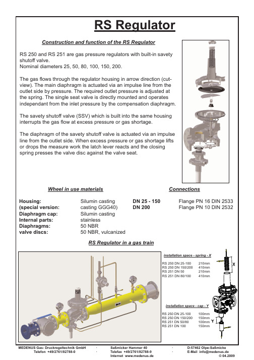
Pressure setting screw Spring disc Setting spring Feet disc Diaphragm disc Regulator main diaphragm Breathing connection Impulse connection Compensation diaphragm Ragulator valve seat Valve disc/Control cone Cover plate Valve for pressure compensation SSV valve seat
· · D-57462 Olpe-Saßmicke E-Mail info@medenus.de © 04.2009
MEDENUS Gas- Druckregeltechnik GmbH Telefon +49/2761/82788-0
MEDENUS Gas- Druckregeltechnik GmbH Telefon +49/2761/82788-0
RS Regulator
Construction and function of the RS Regulator
RS 250 and RS 251 are gas pressure regulators with built-in savety shutoff valve. Nominal diameters 25, 50, 80, 100, 150, 200. The gas flows through the regulator housing in arrow direction (cutview). The main diaphragm is actuated via an impulse line from the outlet side by pressure. The required outlet pressure is adjusted at the spring. The single seat valve is directly mounted and operates independant from the inlet pressure by the compensation diaphragm. The savety shutoff valve (SSV) which is built into the same housing interrupts the gas flow at excess pressure or gas shortage. The diaphragm of the savety shutoff valve is actuated via an impulse line from the outlet side. When excess pressure or gas shortage lifts or drops the measure work the latch lever reacts and the closing spring presses the valve disc against t bar Pa = Pd 22-1.200mbar Q max. 1.100 Nm³/h (2.000) Nm³/h KG-Values V 27,5 459 Nm³/h V 32,5 642 Nm³/h V 42,5 1.097 Nm³/h Gas characteristics: suitable for gas of the gas families 1, 2, 3 and other neutral gaseous media. Ambienttemperature Flow speed (limit 60m/s) SSV max. -20...+60°C
· ·
15 16 17 18 19 20 21 22 23 24 25 26 27 28
Saßmicker Hammer 40 Telefax +49/2761/82788-9 Internet www.medenus.de
SSV disc SSV closing spring SSV spindle Diaphragm disc SSV diaphragm Bearing Minimum pressure spring Maximum pressure spring Maximum setting srew Minimum setting screw Pull button Cap SSV bypass SSV cap
Wheel in use materials
Connections
Housing: (special version: Diaphragm cap: Internal parts: Diaphragms: valve discs:
Silumin casting casting GGG40) Silumin casting stainless 50 NBR 50 NBR, vulcanized
Pd < 400 mbar* 24kg PN16 A=406mm B=305mm L=310mm
Pd < 1.200 mbar* 22kg PN16 A=406m B=305mm L=310mm
*for higher pressure high pressure shaft
MEDENUS Gas- Druckregeltechnik GmbH Telefon +49/2761/82788-0 · · Saßmicker Hammer 40 Telefax +49/2761/82788-9 Internet www.medenus.de · · D-57462 Olpe-Saßmicke E-Mail info@medenus.de © 08.2009
RS 250 DN 25
Special design:
SSV-seat stainless steel contact switch SSV high pressure shaft
Fitting position any 30m/s 1.500mbar
Pd < 200 mbar* 13,5kg PN16 A=328mm B=269mm L=230mm
· ·
Saßmicker Hammer 40 Telefax +49/2761/82788-9 Internet www.medenus.de
· ·
D-57462 Olpe-Saßmicke E-Mail info@medenus.de © 04.2009
RS Regulator
1 2 3 4 5 6 7 8 9 10 11 12 13 14
· ·
Saßmicker Hammer 40 Telefax +49/2761/82788-9 Internet www.medenus.de
· ·
D-57462 Olpe-Saßmicke E-Mail info@medenus.de © 04.2009
Pe = Pu max. 6 bar Pa = Pd 22-1.200mbar Q max. 150 Nm³/h (300) Nm³/h KG-Values V 17,5 170 Nm³/h V 27,5 420 Nm³/h Gas characteristics: suitable for gas of the gas families 1, 2, 3 and other neutral gaseous media. Ambienttemperature Flow speed (limit 60m/s) SSV max. -20...+60°C
RS 250 DN 80
Special design:
SSV-seat stainless steel contact switch SSV high pressure shaft
Fitting position any 30m/s 1.500mbar
Pd < 130 mbar* 28kg PN16 A=406mm B=305mm L=310mm
· ·
Saßmicker Hammer 40 Telefax +49/2761/82788-9 Internet www.medenus.de
· ·
D-57462 Olpe-Saßmicke E-Mail info@medenus.de © 08.2009
Pe = Pu max. 6 bar Pa = Pd 22-1.200mbar Q max. 500 Nm³/h (750) Nm³/h KG-Values V 17,5 186 Nm³/h V 27,5 459 Nm³/h V 32,5 642 Nm³/h Gas characteristics: suitable for gas of the gas families 1, 2, 3 and other neutral gaseous media. Ambienttemperature Flow speed (limit 60m/s) SSV max. -20...+60°C
