挡风墙对电站空冷岛的影响
空冷岛防冻应急预案

空冷岛防冻应急预案1.1总则1.1 为确保空冷机组安全稳定运行,防止空冷凝汽器发生冬季冰冻事故,依据《XX公司重大突发事件(事故)应急管理办法》,特编制本预案。
1.2 本应急预案适用于XX集团公司所属各发电企业,各企业应根据实际情况制定本企业预案。
1.2事故类型和危害程度分析2.1 空冷岛技术是近年来在电力建设领域中采用的一项新技术,它的主要特点是能够根据电厂所处的地理条件,充分利用自然风的能量进行机组水冷却,从而达到节约水资源的目的。
2.2 空冷机组在正常运行期间并且当环境温度低于某一结霜点时,在逆流凝汽管束的上部会发现结霜,这是由于那里有不可凝气体的过冷现象发生。
如果这种状况持续一段时间,就可能会逐渐地堵塞逆流凝汽管束芯管的下端,并且妨碍不可凝气体的排出。
如果频繁发生,凝汽器芯管就可能变形甚至被损坏,导致机组出力不足甚至被迫停运。
因此,空冷机组在接近冰点的温度下运行期间,要严格采取一切措施避免凝结水过冷现象。
2.3 各厂根据本厂实际情况概括介绍空冷系统的型式及故障特点。
2.4 预警级别二级预警:运行中一列管排的凝结水温度低于规程规定,运行人员调整无效,该列冷凝器被迫解列。
空冷系统的冷却效果能够保持机组负荷的需要,不影响机组的出力。
应及时查明原因消除。
一级预警:冷凝器被迫解列的列数较多,已影响了机组的出力并有被迫停机的可能。
应立即组织应急抢修。
1.3应急处置基本原则3.1要本着缩小范围和缩短检修时间的原则,组织人员尽快确定故障点,实施事故处理恢复方案。
3.2由于空冷系统的冷却风机有较大噪音,因此在空冷系统检修过程中应注意噪音防护。
3.3 在抢修过程中严格按照规程作业,严格执行风险控制措施,避免事故扩大和发生人身事故。
3.4 防止检修人员冻伤。
1.4组织机构及职责1.4.1组织机构组长:生产厂长(总工程师)副组长:生产部、运行部、检修部负责人成员:生产部、运行部、检修部汽机专业负责人,1.4.2职责4.2.1 提出修订应急预案,负责定期组织演练,监督检查各部门在本预案中履行职责情况。
330MW机组直接空冷岛运行防冻调整措施

330MW机组直接空冷岛运行防冻调整措施为了满足直接空冷机组冬季安全、经济运行的要求,通过分析风机电耗率和机组背压之间的关系,结合机组历史运行数据、空冷岛温度分布规律、防冻控制方法,给出了防冻控制方法,并制订了兼顾机组节能运行的优化控制策略。
该控制策略在330MW直接空冷机组上实施后,机组冬季运行背压平均可降低1kPa,在满足机组防冻安全的基础上实现了经济运行。
标签:330MW直接空冷机组;背压;风机;防冻;节能我厂2×330MW循环流化床机组采用直接空冷凝汽式汽轮机,额定背压为14.5KPa。
ACC(空冷)系统共有6列空冷凝汽器,位于空冷岛34米平台,由东向西排列分别为60、40、20、10、30、50列,其中10和20列为启动列,每列有3个顺流单元和2个逆流单元(2、4单元)。
空冷风机转速可通过变频器在0~50Hz无级调速,当环境温度≥20℃时投超频可达55Hz。
1 前言目前,直接空冷机组因具有良好的节水性在我国北方地区得到了广泛的应用。
直接空冷系统采用机械强制通风,将环境空气作为冷却介质,利用换热翅片管束使管内的水蒸气与管外的空气发生热交换,将汽轮机内做完功的乏汽冷却至液态水,实现热功转换中冷端散热的目的。
直接空冷机组运行几年后,大型冷端换热器——空冷岛的性能会逐渐下降,空冷岛翅片管冬季防冻、春秋季节防大风、夏季换热效果差等问题也逐渐显现。
另外,我国北方地区火电机组常面临调峰任务重、发电负荷不足等问题,开展空冷机组冷端优化运行工作非常重要。
2 空冷机组防冻研究现状我国北方冬季气温很低,像内蒙古薛家湾冬季最低温度可达到-25℃,空冷岛低温区域很容易发生冻结现象。
国内外关于空冷岛节能运行的文献有很多,但研究空冷机组防冻机理的文献较少。
虽然对直接空冷机组冷端防冻的机理进行了一定程度的研究,但是兼顾冷端防冻与节能功能的自动调节方案很少。
本文针对神华准能矸石发电有限责任公司的2台330MW汽轮发电机组每年冬季都会面临空冷系统运行防冻比较困难的问题进行了研究。
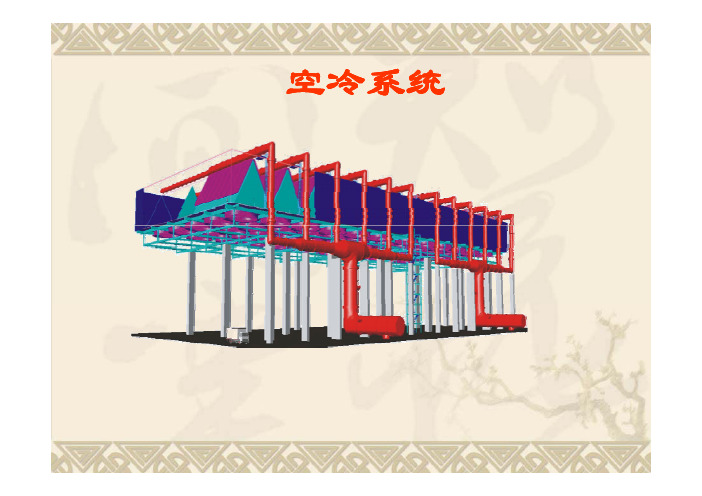
空冷岛简介
空冷严密性试验
给所有的安装焊缝和法兰连接涂肥皂。 为 进行泄漏试验 必须在管道的各个点放置盲 进行泄漏试验, 板,例如在汽轮机的前面 ,在安全阀的前面, 在防爆膜的前面 在泵的前面等。 在防爆膜的前面, 在排 气管道安装完成后必须进行空冷凝汽器严密性 试验根据设备厂家图纸设计要求及中华人民共 和国电力行业标准《火力发电厂空冷塔及空冷 凝汽器试验方法》DL/T 552-95中规定的标准 552 95中规定的标准 进行验收。
2、采用空冷,厂址选择不受限 2 采用空冷 厂址选择不受限 制 3、由于空冷器空气侧压力降为 100‾200Pa 左右,所以运行 左右 所以运行 费用低。 4、空气腐蚀性低,不需要采取 任何清垢的措施 5、空冷系统的维护费用一般为 水冷却系统的 20‾30%
4、水的运行费用高,循环泵的 4 水的运行费用高 循环泵的 压头高 5、在水冷器中,某些生物能附 着在换热器表面上 需要停下 着在换热器表面上,需要停下 设备清除,增加了维护费用
国内电站空冷系统供应商现状: 国内电站空冷系统供应商现状
1、美国 美国SPX(斯必克)公司在中国空冷市场上的占有 率约35%,在天津、张家口分别设有两个独资管束生产 中 2、德国GEA(基伊埃)公司德国GEA公司系空冷技术 的创始人,其技术 直处于世界领先地位,在世界空冷 的创始人,其技术一直处于世界领先地位,在世界空冷 市场上的占有率超过60%,在中国空冷市场上的占有率 约35%。 3、首航艾启威冷却技术有限公司。首航艾启威冷却技 术(北京)有限公司是由北京首航波纹管制造有限公司和 瑞士IHW联合设计集团共同投资的中外合资企业。 联合设计集团共同投资的中外合资企业 4、北京龙源冷却技术有限公司、哈尔滨空调股份有限 公司等。 公司等
空冷度夏和防冻措施

夏季满发措施从目前投用的多台600MW直接空冷机组的实际运行情况看,其夏季低真空问题已成为影响机组安全经济运行的主要问题。
由于夏季运行工况正处于电网渡夏高负荷运行时期,且从机组的调峰角度看日负荷的高峰负荷也正是环境温度高的时段。
因此机组如何在夏季高温条件下实现满发具有十分重要的现实意义。
下面从设计、安装、调试和运行等几方面对如何保证空冷系统夏季满发进行分析,从而提出预控措施。
(一)设计方面:我厂设计夏季满发温度:26.07℃满发背压:25.204KPa 其中全年不满发小时数为192小时。
我公司从设计之初就从以下几方面采取措施,保证机组在夏季高温条件下可以实现满发:1)根据我公司所处地理位置的实际情况,充分论证,合理选择合适的空冷散热面积。
2)设计选取3台100%容量的真空泵增加机组抽真空能力,满足夏季高温情况下的抽真空能力。
3)设计时空冷系统满发背压为30 kPa,而机组运行时考核背压为35 kPa,留有5kPa裕量。
4)空气供应系统轴流风机采用变频调速方式驱动,选择合适的电动机容量,保证风机转速达到110%以上以增加通风量,提高冷却系统的散热能力。
5)采用高压冲洗水泵,在每年夏季来临之前,利用高压除盐水清洗空冷器的外表面,去除附着在其上的污垢和尘埃,减少热阻,保持空冷器良好的传热效果。
相同条件下比较,可能提高机组出力5-10%左右(因污垢程度的不同有所差异)。
(二)安装方面:1.严格执行各项安装标准,实施洁净化施工,控制空冷系统各部件严密、无漏泄,管束内部无毛刺、焊渣、无变形,所有设备安装质量合格。
2.严格进行空冷部分打压试验,所有参加气压试验的蒸汽排汽管道、蒸汽分配管道、换热器管束、凝结水回水管道、抽真空管道等系统无泄漏点。
3.排汽装置先进行灌水试验,灌水高度至低压缸端部汽封下100mm。
(三)调试、运行方面:1.深化调试深度,对空冷系统各项调试工作提前准备、预控,并借鉴同类型机组经验、方法,细化调试方案。
空冷岛防冻
冬季空冷岛安全、经济运行技术措施为了确保空冷系统进入冬季的安全、经济运行,根据实际情况,针对空冷系统的投、停及正常运行维护、异常处理情况下,特制定以下措施,望各值认真学习、执行。
一、日常维护工作1.正常运行时空冷岛每班进行两次巡回检查,检查项目增加:就地温度计显示的环境温度、伴热带工作正常、防冻帆布防火情况、挡风墙彩板无松动、平台孔洞封堵正常、风机室之间的门关闭正常。
2.环境温度下降到-3℃以下时,安排人员进行空冷岛翅片就地测温,并将数据详细记录到空冷测温表中。
3.就地测温工作每班进行两次,保证顺流区管束表面温度在35℃以上,(尤其注意下半部分),逆流区管束表面温度在10℃以上,(尤其注意上半部分)集控DCS盘面各列抽空气温度低于凝结水10℃时,要进行重点侧温,防止管束冻结。
4、保证空冷岛进汽量在冬季防冻最小防冻流量150t/h 以上,空冷岛进汽流量=主汽流量-各段回热抽汽量(主汽流量的35%)5、主汽压力严格按照滑压曲线运行,相同负荷下,主汽压力升高时,主汽流量下降,这样进入空冷岛的蒸汽量降低,不利于防冻。
6、冬季排汽背压应根据环境温度、凝结水、抽空气温度综合考虑后设定。
正常情况下按额定背压13.6kPa运行。
(附背压对功率关系修正曲线)二、极端工况的检查规定1、极端工况是指:1)环境温度低于-25℃以下时;2)机组启、停时;3)低负荷时;4)事故处理时;5)空冷岛进汽量小于最小防冻流量时;2、上述第一项的检查、测温工作安排专人,每小时进行一次。
三、机组启动时1、机组在冬季启动前(环境温度≤0℃),应检查空冷排气装置各列进汽隔离阀关闭,各列凝结水阀、抽空气阀开启。
2.锅炉点火前,将机组管道疏水一、二次门关闭并“挂禁操”,确保空冷系统无蒸汽进入。
3.锅炉点火前,机组送轴封后启动三台水环真空泵开始抽真空,当机组背压降至50PKa,时关闭抽真空旁路阀。
利用ACC逆流区抽真空,系统继续降低机组背压,此时锅炉点火。
空冷岛挡风墙最佳高度的数值模拟
收 稿 日期 : 2 1 一o 0 1 4—1 8 作 者 简 介 : 曾强( 9 1 ) 男 , 1 7 一 , 河北保定人 , 工程师 , 主要从事直接空冷机组集控运行 。
几何 模 型 ( 1 。该 台机 组 有 5 图 ) 6个 空冷 单 元 , 计算 范
围为 6 0m × 7 0m × 6 0m, 风墙 距凝 汽器 ( 0 0 0 挡 即过 道 ) . 图 2 ; 炉房 长 ×宽 ×高为 4 1 2m( )锅 0m×6 0 m×
岛挡风墙 的最 佳高度 。
部 流场进行 数值 模拟 , 分析 在 不 同风 速 下 空冷 岛挡 风墙 高度 对凝 汽 器换 热 效率 的影 响 ,
并得 出最佳 空冷 岛挡 风墙 高度 为 1 ~1 1 2m。
[ 关 键
词] 直接 空冷凝 汽 器 ; 冷 岛; 风墙 ; 热 效率 ; 空 挡 换 流场
6 .1 [ 中图分类 号] T K 2 4
NUM ERI CAL I ULATI SM oN FoR oPTI AL M HEI GHT oF WI NDS ELDI HI NG ALL W oN R AI CooLI NG S I LAND Z ENG a g. ANG hg n Qin W Z ia g
G u hu n z o we n r to d, a d n 7 00 He e o i c PRC o a Di g h u Po r Ge e a in Co Lt B o i g 0 1 3, b iPr v n e,
Ab t a t By u i g t e smpl go ihm nd t sr c : s n h i eal rt a he k一£ t r ulnc o li u b e em de n CFD o t r , he nu rc I s f wa e t me ia sm u a i x e n lfo fe d f r ar c o i s a d of a 6 0 M W i o i g un t ha e a re i l ton ofe t r a l w il o i o lng i l n 6 a r c oln i s be n c r i d o ,he i fue e o nd hil ng wa l e g po he he t e c n f iinc f c de s r u e ut t n l nc f wi s e di l h i ht u n t a x ha ge e fce y o on n e nd r d fe e n p e i nays d, nd t ptm a e g fwi ds e d n wa lo t i o i s if r ntwi d s e d beng a l e a he o i lh i hto n hi l i g l n he ar c ol ng i— lnd b i g ob ane I he c s fwi s e d ng wa lheghtb i g 1 , h a x h ng fiinc s a e n t i d. n t a e o nd hi fc e y i 2 t ghe t i h l h i hti u t r i r a e o he c t a y, h a x h ng f ii n y wild — he hi s ,ft e wa l e g s f r he nc e s d, n t on r r t e he te c a e e fce c l e
600MW直接空冷凝汽器加装下挡风墙的数值研究
.
p
=
(+ 卜 (+器 c 器 誊 pt 4 k, x
Q a ×10 × 0% %
【 ) ( 6 6
此外 , 由于 考 虑 空 冷 平 台 还 有 热 量 交 换 ,须 式 中 :Q 为 空冷 单 元 的实 际换 热 量 ;Q 为 空 冷 单
运 用 能量 方程 :
台 的影 响 。
作 用 下 ,形 成 了 强 烈 的 热 风 回 流 和 “ 灌 ” 现 倒 象 ,使 空 冷 凝 汽 器 的换 热 效 率 受 到 极 大 影 响 。
为 解 决 以上 问题 ,采 取 在 原 有 的 空 冷 凝 汽 器
以 图 2 中箭 头 所 示 的 全 年 的 主 导 风 向 为 例 , 当 环 境 风 场 的 速 率 小 于 2 m s时 , 自然 风 的 作 用 /
1 O u+ (t
采 用 标 准 k一8湍 流模 式 :
一
2 数 值 求解 及 结果 分 析
() 3
量 定 义 为标 准 风机 风 量 。对 于 每 个 空 冷 单 元 而 言 ,
其 实 际换 热 量 除 去 标 准 工 况 下 空 冷 单 元 的标 准 换 热 量 ,所得 到 的无 量 纲 数 可定 义 为 换 热 效 率 。
的 结 构 有 重 要 的实 际意 义 。
点 为下 挡 风 墙 两 侧 ,故 对 其 网格 进 行 加 密 来 提 高
的 环 境 横 向风 的 作 用 ,会 在 空 冷 凝 汽 器 迎 风 面 前 计 算 精 度 。
计 算 模 型 中 的 空 冷 平 台 由 1 空 冷 单 元 6X7个
模 拟 ,分析计算 了三种 不 同位置加装下挡风墙 对直接 空冷凝汽器风机风量的影响 。在风速 大 于 7m s时, /
600MW直接空冷机组的防冻浅析
600MW直接空冷机组的防冻浅析作者:刘君来源:《中小企业管理与科技·下旬刊》2011年第05期摘要:我国的直接空冷技术应用到火电厂起步较晚,在对于空冷机组的防冻工作虽然积累了很多宝贵的经验,但目前仍在经验的积累和探索中。
文中结合宁夏大唐国际大坝发电厂的运行经验针对600MW直接空冷机组启动过程中防冻的一些理念进行了阐述,并结合机组运行中的防冻工作制定了防冻措施以及空冷散热器冻结后的化冻措施。
关键词:直接空冷冻结原理启动防冻低背压启动化冻措施1 直接空冷系统概述宁夏大唐国际大坝电厂2*600MW机组是东方汽轮机厂采用日本日立技术设计成产的首台NZK600-16.7/538/538型亚临界、一次中间再热、两缸两排汽、直接空冷凝汽式汽轮机。
直接空冷系统是由斯必克斯公司生产的三排管直接空冷,主要由以下三部分组成:1.1 空冷散热器汽轮机排汽经凝汽器下方设置的排汽装置后,再经一根φ8000的排汽主管道穿过汽机房外。
排汽主管道垂直上升到水平管后,从水平管上接出8根上升支管,水平与空冷散热器上联箱连接。
空冷散热器搁置在45m高的散热器平台之上,64组空冷散热器分为八个冷却单元垂直A 列布置,每个冷却单元有八组空冷散热器,其中有六组为顺流,两组为逆流。
每组空冷散热器以接近60℃角组成等腰三角形A型结构。
空冷散热器中顺流散热器管束是冷凝蒸汽的主要部分,可凝结75-80%的蒸汽。
逆流散热器管束主要是为了将系统内的空气和不凝结的气体排出。
避免运行中在空冷散热器内的某些部位形成死区,冬季发生冻结。
1.2 空气冷却系统64台变频冷却风机设置在每组空冷散热器的下部,使空气流过散热器外表面将排汽凝结成水,顺管壁流入冷却管束的凝结水箱。
1.3 抽空气系統抽空气管道接在每一个冷却单元逆流空冷散热器的上部,运行中不断将空冷散热器中的空气和不凝结的气体抽出,以保持系统真空。
2 直接空冷散热器冻结原理在机组处于空负荷或低负荷运行时,蒸汽流量很小,即进入空冷散热器的蒸汽流量很小,当蒸汽由空冷散热器进汽联箱进入冷却管束后,在由上而下的流动过程中,冷却管束中的蒸汽与外界冷空气进行热交换后不断凝结。
660MW机组空冷岛防冻原理及措施

660MW机组空冷岛防冻原理及措施内蒙古大唐国际锡林浩特发电有限责任公司,锡林浩特026000摘要:针对寒冷地区660MW机组空冷岛在启停、运行过程中,易发生空冷岛扇区管束冻结,造成空冷岛扇区管束变形,严重者造成管束泄漏,严重影响机组的安全稳定运行。
本文针对空冷岛管束冻结原因进行分析并提出防冻措施。
关键词:发电厂;空冷岛;防冻引言:大唐锡林浩特发电有限公司位于锡林浩特市东郊,冬季气候寒冷,2020年冬季达历史最低气温-41℃。
特殊的地理位置使我公司空冷系统的防寒防冻工作是重中之重。
空冷凝汽器通过向大气释放热量对汽机排汽或汽机旁路的减温过热蒸汽进行冷凝。
它是采用机械强制通风换热器,由于空冷岛的换热管束是直接暴露在寒冷大气中,所以,在冬天环境温度较低的时期换热管很容易发生冻堵,管束冻堵严重时会变形,甚至发生破裂,严重时会导致机组不能正常运行,导致非停事故发生。
一、空冷岛工作原理:空冷凝汽器由8列“M”屋顶型翅片管排构成。
每组管排包含7个模块(4个一次模块和3个混合模块)。
每个模块由24个翅片管束构成。
屋顶结构下方布置的轴流风机迫使空气流过翅片。
蒸汽流通过大管径管道进入凝汽器。
管道系统分成16个支线立管和顶部蒸汽分配管。
蒸汽通过分配管进入顺流管束的翅片管。
大约85%的蒸汽通过顺流冷凝管束冷凝(蒸汽和凝结水:自上而下顺流)。
凝结水和残留的未冷凝蒸汽通过"A"型屋顶结构底部的大尺寸蒸汽/凝结水联箱收集。
剩余蒸汽(大约15%)通过与蒸汽/凝结水联箱的底部连接进入逆流冷凝管束的翅片管道。
蒸汽通过逆向流动模式获得冷凝,即不可冷凝的气体向上流动,而凝结水向下流入蒸汽/凝结水联箱。
通过这种方式,凝结水总能从蒸汽获得热能,避免发生过冷现象。
不可冷凝的气体在逆流冷凝管束顶部附近汇集,被吸入逆流冷凝管束顶部布置的空气集管内。
这些集管通过空气管线与抽真空系统相连,以便从空冷凝汽器内抽走不可冷凝的气体。
冷凝水收集到蒸汽凝结水联箱,通过重力疏水进入汽机排汽装置,再用凝结水泵抽到锅炉系统。
多孔介质模型在300MW空冷岛下挡风墙中的应用
2Sa lc i P w rPa nn ei t eEetc o e l igD s n& R sac ntue B in 0 0 4, hn ) t r n g eerhIstt, e ig10 9 C ia i j
Z HOU G l Xl, HON B -u , HANG S u xa a -i Z l l G fE u ain o n i o ntr ga d C nrlfrP we 1 K yL b rtr fMiit o d c t f y o Co dt n Mo i i n o t o o r i on o
Ab ta t B s d o h e e r h o 0 sr c : a e n t e r s a c f 0 MW ie tarc oe nt e ma e n mei a i lt n o ee r a o m e 3 d r c - o ld u i,w k u rc lsmu a o ft  ̄e n l w d i i h l f
( 1华北电力大学电站设备状 态检测与控制教育部重点实验室, 定 0 10 ; 保 70 3 2 国核 电力规 划设计研 究院 , 北京 10 9 ) 004
摘要 : 以某 30 W 直接空冷机组为例 , 0M 利用 C D软件对其空冷岛外部流场进行 数值模拟 。分析 了不 同结构形 式的 F 下挡风墙对 空冷凝 汽器换热效率 的影响 。指 出了在风速大于 6 / 时 , m s 空冷凝汽器换热效率的降低是 “ 倒灌 ” 现象 与热风回流综合作用的结果。计算结果表明, 在空冷平台四周的外沿下方加装直面下挡风墙后比不加时换热效率 提高了 l.% , 装面积比为 117 、 21 加 :.3夹角为 9。 O 的多孔折面下挡风墙后 , 空冷凝汽器 的平 均换热效率 比加直 面实 心挡风墙提 高了 2 1 , . % 更加有利于凝汽器的换热。为进一步改进空冷岛 的结构提供 了理论依据。
浅谈空冷岛系统的防冻处理

浅谈空冷岛系统的防冻处理发布时间:2021-06-23T02:30:05.189Z 来源:《中国电业》(发电)》2021年第5期作者:王贵文[导读] 1.1直接空冷系统,又称空冷岛,是指将汽轮机的乏气直接用空气来冷凝,所需冷却空气通常由机械通风方式供应,其散热器是由外表面镀锌的椭圆形钢管外套矩形钢翅片的若干个管束组成的。
晋能控股电力集团阳高热电公司山西阳高 038100摘要:北方地区缺水情况比较严重,针对缺水问题北方火电厂凝汽器排汽冷却系统采用空冷岛系统。
直接空冷系统具有环保、节能、节水等主要特点,空冷技术在北方大型火电厂应用比较广泛。
由于空冷机组在启动初期和低负荷运行期间,蒸汽流量较少,翅片管存在不同程度的冻结现象,给运行调整带来较大安全隐患。
本文主要对350MW空冷机组空冷岛防寒防冻进行分析探讨以提高机组经济性和安全性。
关键词:空冷岛防冻措施汽轮机;翅片管1、空冷岛系统概述1.1直接空冷系统,又称空冷岛,是指将汽轮机的乏气直接用空气来冷凝,所需冷却空气通常由机械通风方式供应,其散热器是由外表面镀锌的椭圆形钢管外套矩形钢翅片的若干个管束组成的。
采用直接空冷系统的优点为大幅减少了需水量,一次性投资低,易于在所有大气温度下实现冷却空气的均匀和稳定分布。
其缺点是风机消耗电力,冷却空气与汽轮机乏气直接进行热交换。
1.2阳高热电公司空冷系统采用直接空冷系统,空冷岛的主要组成部分包括:(1)汽轮机低压缸排汽管道;(2)空冷凝汽器管束;(3)凝结水系统;(4)抽气系统;(5)疏水系统;(6)通风系统;(7)直接空冷支撑结构;(8)自控系统;(9)清洗装置。
主要运行原理为:把由蒸汽轮机的低压缸内做完功后的乏气从汽轮机的尾部引入大口径的蒸汽管道,输送到汽轮机房之外的空冷平台上,再经过配气管送到众多翅片管换热管束内,外界的空气由大径轴流风机驱动穿越翅片管束的翅片间隙,继而把翅片管束内的蒸汽冷凝成凝结水,使其重力回流到凝汽器内。
挡风墙对空冷岛的防风效果分析
挡风墙对空冷岛的防风效果分析摘要:环境风引起的“热风回流”和“倒灌”降低空冷凝汽器换热效率,在空冷岛安装挡风墙,能够有效的降低“热风回流”和“倒灌”对空冷凝汽器换热的影响。
以在空冷电厂应用较多的上挡风墙为例,从挡风墙的防风效果和挡风墙的布置及结构形式对空冷岛换热的影响等几个方面对挡风墙在空冷岛的应用进行了分析研究,下挡风墙目前停留在理论研究阶段。
关键词:直接空冷凝汽器;热风回流;倒灌;挡风墙中图分类号:tk264.10 序言火电空冷机组由于节水,近几年发展迅速,截止2011年,空冷机组装机容量已经超过1亿千瓦,约占我国火电机组总装机容量的1/7,其中直接空冷机组以其性能好,投资省、占地面积小而被广泛应用,是空冷机组发展的趋势。
但是大型空冷发电机组在我国投入运行时间短,很多方面还不成熟,研究空冷机组以提高其经济性和可靠性具有重要意义。
空冷凝汽器的排汽压力影响整个空冷机组的经济性,文献[1-2]分别以300mw和600mw直接空冷机组为例,在考虑排汽管道的压损,排汽口至空冷凝汽器入口间水蒸气柱高度压力及排汽管对环境散热量的条件下,建立直接空冷机组冷端系统特性曲线,同时分析了空冷凝汽器压力及管道压损的变工况特性。
文献[3-4]用fluent对空冷塔外部流场进行数值模拟,研究了环境风对直接空冷凝汽器换热的影响。
文献[5]提出几种在夏天高温天气提高空冷凝汽器散热量的措施。
在夏季高温天气,由环境风引起的“热风回流”和“倒灌”,影响空冷凝汽器换热,进而使机组背压急剧升高,降低了机组的经济性和可靠性。
对此,空冷电厂一般安装挡风墙以降低环境风对空冷凝汽器换热的影响。
本文从挡风墙的防风效果和挡风墙的布置及结构形式对空冷岛换热的影响等几个方面对挡风墙在空冷岛的应用进行了研究。
1 安装挡风墙对空冷单元防风效果分析1.1 环境风对空冷凝汽器的换热的影响直接空冷凝汽器安装在空冷平台上,由空冷单元组成,空冷平台一般安装在锅炉汽轮机的背后,直接暴露在空气中,通过空冷风机吸入的空气冷却汽轮机排汽。
300MW机组空冷岛挡风结构分析设计

我 国是 水资源 严 重短 缺 的国家 , 而火 力发 电厂 位 于工 业 用 水 大 户之 首 , 2 0 仅 0 6年 , 国火 力发 电 全 量 为 2 7 3 千瓦 [ , 35 亿 1 占总发 电量 的 8 % , ] 3 耗水 量超 过6 O亿立 方米 。 空冷技 术是 火力节 水型发 电的有效 途径 , “ 在 十一 五 ” 间 , 期 国家 大力推 广 空冷 机 组等节 水 型机 组 建设 , 以适 应 我 国西 部缺 水 而 煤炭 储 量 丰 富地 区的煤 电建设 。大 型 空冷 电厂与 同容量 湿冷 电
空冷岛属于高柔结构 , 水平 向风荷载在空冷 岛结构 计 算 中起 控制 作 用 , 而挡 风 墙 上 的风 荷 载是 整 个 结 构 风荷 载的 主要部 分 。因此 , 设计 出安 全耐久 、 济 经
合 理 的挡风墙 结构 不论 对空冷 岛散 热 系统高 效工 作 还 是承 重结构 体 系合理 受力都 起着 重要 的作 用 。 2 空冷 平台 挡风墙 计算 模型 通 过对 已建和 在建 项 目的空冷 平 台挡风 墙结 构 形式 调查 , 风结 构 均采 用 型 钢骨 架 外 贴彩 钢 板 组 挡 成, 而型 钢骨 架部分 归纳 为两 种不 同的 结构形 式 : 疏 柱 加梁 型 ( 以下 称疏 柱 型 , 图 1 和 密 柱无 梁型 ( 见 ) 以 下 称密 柱型 , 图 2 。本 文 以某 电厂 已完工程 ( 风 见 ) 挡
墙 采用疏 柱型 ) 为例 , 分别 采用 以上 两种 结构形 式 的 挡 风 墙进行 相 同工程 设 计 条件 下 的 对 比分 析 , 期 以 获 得 更经 济合 理 的挡 风 墙 结构 形 式 , 今后 同类 工 为 程 设计提 供参 考依据 。
2 1 工程设 计 条件 .
防风网对空冷岛换热效率的影响及防风网优化
DN hny,H NWe,IOWe,INYn—n ,I u- i IGZ e— C E i A iTA og i L X ez u Q xg h
( i x l tc oe R s r steoNnx l t o e Cm a Ynha 502C i ) Nn i E ci Pwr e a hI t t f i iEe r Pwr o pn i un 00 ,h a g a e r e c n i g a ci u c y, c 7 n
第5 3卷 第 6期
21 0 1年Leabharlann 1 2月 汽轮机
技
术
Vo . 3 No 6 15 . De . 0 l c 2 1
TURBI NE TECHN0L0GY
防风 网对 空 冷 岛换 热 效 率 的影 响及 防风 网优化
丁振 宇 , 巍 , 陈 乔 炜 , 田永兴 , 李学智
关 键 词 : 境 风 ;let 值 模 拟 ; 风 网 ; 接 空 冷 岛 环 Fu n 数 防 直
分类号 : K 6 . l T 24 1
文献标识码 : A
文章编号 :0 1 84 2 1 )604 - 10 — 8 (0 1 0 -4 70 5 5
Wid hedo eHet rnfrE ii c f i c A rC o dI a d n s i nt a T a s f c n yo r t i ol s n l h e e D e e l
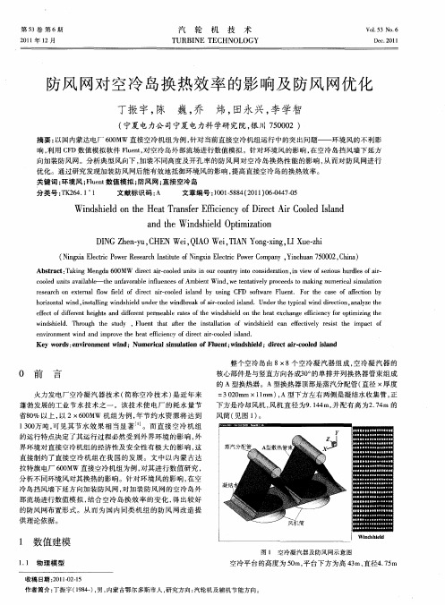
Ab t a t T k n n d 0 MW ie tar c o e n t i u o n r n oc n i e ain,n ve f ei u u d e far sr c : a i g Me g a6 0 d rc i—o l d u i n o rc u t i t o s r t s y d o i iw o r sh r l so i- s o c o e n t a al be t e u fv r b ei f e e so o l d u i v i l- h n a o a l nl n e fAmb e tWi d. e tn ai ey p o e d oma i gn me c l i lt n s a u i n n w tt l r c e st k n u r a mu ai e v i s o r s ac n e tr a o ed o ie t arc oe sa d b u i g C D s f r l e t F r t e c s f afc in b e e rh o xe n l f w f l f d r c i o ld iln y sn F ot e F u n . o h a e o fe t y l i — wa o h r o t n i sal g wi d h ed u d rte w n b e k o i c oe sa d o i n a wid,n t l n n s il n e i d r a far o ld il n .Un e e tp c l i d d rc in。 n lz h z l i h — d r h ia n ie t t y w o a ay et e efc fd f r n eg t a d df r n eme b e r t so e w n s il n t e h a x h n e e ce c r o t zn h f to i e e th ih s n i e e tp r a l a e ft i d he d o h e t c a g f in y f p i i g t e e f f h e i o mi wi d h e d T ru h h s d . 1 e t h t at r t e i sal t n f w n s il a efc iey r ss h i a t f n s il . h o g t e t y F u n t a fe h n t ai o i d he d c n f t l e i t e mp c o u l o e v t e vr n n n n rp o e t e h a f c e c f i c i. o ld i a d n i me t o wi d a d i r v h e tef in v o r tarc oe s n . e i d e l Ke r s el i o me t wi d;Nu e ia i l t n o l e t w n s il y wo d : l r n n n v m rc lsmu a i fF u n ; o i d h ed;d r c i・ o ld ilnd i e ta r c o e sa
空冷岛概述[1] 2
![空冷岛概述[1] 2](https://img.taocdn.com/s3/m/c4f5a0f2f705cc1755270934.png)
抽真空系统
水环真空泵 大南湖电厂 每台空冷机组设置3台 水环真空泵
平台的吊装
特别注意在地面 进行钢结构组合时, 必须有标准的组合平 台。 高强螺栓的紧固 必须达到图纸规定的 设计要求,经检查合 格后再进行吊装。
钢平台吊装结束后注意事项
一、保证平台的水平度、 直线度、以及高强螺栓 的扭矩,符合图纸设计 要求。 二、保证钢平台的安装长 宽跨距尺寸。 三、在各项指标都符合设 计要求后,进行空冷平 台的二次灌浆。 四、灌浆结束后才能进行 平台上部结构的安装。
热风回流
减少热风再循环的措施有:
(1)在空冷平台周围设置挡风墙。 (2)在不同的空冷凝汽器单元之间设置分隔墙 (3)降低空冷平台下面进风口的空气流速,减少负 压区。 (4)采用喷雾加湿系统。其主要原理是高气温时段 在空冷凝汽器迎风面喷雾除盐水,一部分与翅片管 束进行热交换,水雾在管束表面升温后蒸发,利用 汽化潜热吸收了热量;另一部分雾化后的小水滴与 环境空气直接换热,降低了环境温度,增大了传热 温差,强化了传热效果。
管束结构
翅片管的选择
翅片管是空冷器的核心和关键部件 它的性能直接影响空冷器的性能和作 用。对翅片管的基本要求如下:
①良好的传热性能。 ②良好的耐温性能。 ③良好的耐大气的腐蚀性 能。 ④良好的耐热冲击力。 ⑤易于清理尘垢。
⑥较低的制造费用。 ⑦足够的管内耐压能力, 较低的管内压降。 ⑧较小的空气侧阻力。 ⑨良好的抗机械振动性能。 ⑩易于取得的金属材料
2、水冷却器结构紧凑,冷却面 积比空冷器要小得多。
3、水冷却对环境气温的变化不 敏感。 4、水冷器可以放在其它设备之 间。 5、一般的管壳式换热器即可满 足要求。
19-不同风向条件下空冷岛运行特性的数值模拟
第26卷第3期2009年6月现 代 电 力Modern Electric Power Vol 126 No 13J une 2009文章编号:100722322(2009)0320071205 文献标识码:A 中图分类号:T K124;T K26411不同风向条件下空冷岛运行特性的数值模拟贾宝荣,杨立军,杜小泽,杨勇平(华北电力大学电站设备状态监测与控制教育部重点实验室,能源的安全与清洁利用北京市重点实验室,北京 102206)Numerical Simulation of Operation Performance of Direct Air 2cooled System inDifferent Wind DirectionsJia Baorong ,Yang Lijun ,Du Xiaoze ,Yang Y ongping(Key Laboratory of Condition Monitoring and Control for Power Plant Equipment of Ministry of Education ,Key Laboratory of Safe and Clean Energy Technology ,North China Electric Power University ,Beijing 102206,China )摘 要:环境横向风的存在是影响空冷岛运行特性的主要因素之一。
利用数值模拟方法,以2×300MW 直接空冷机组空冷系统为研究对象,分析了环境风速分别为3m /s 和10m /s 时,不同来流风向对空冷岛运行特性的影响。
结果表明:不同环境风向条件对空冷岛的影响差别很大,炉后来风最为恶劣,此时空冷岛迎面风速最小,凝汽器冷却空气温度最高,回流率最大。
并且环境风速越大,对空冷岛运行特性的影响越大。
关键词:空冷岛;运行特性;迎面风速;热风回流;数值模拟Abstract :The existence of ambient cross wind is one of t he main f actors w hich aff ect t he operation perf orma nce of t he direct air 2cooled system.Based on 2×300M W direct air 2cooled units ,t he operation perf orma nce of t he direct air 2cooled system at natural wind speeds of 3m/s a nd 10m/s a nd in diff erent wind directions a re analyzed wit h numerical simulations.Results show t hat t he operation p erf ormance of t he direct air 2cooled system is rema rkably influenced by t he natural wind directions.The wind blowing f rom t he boiler house to t he air 2cooled system is t he most unf avorable ,in w hich t he windward air has t he smallest velocity ,t he cool 2ing air has t he highest temperature a nd t he hot air recircula 2tion flow has t he biggest ratio.The higher t he speed of t he natural wind ,t he la rger t he eff ect on operation perf orm 2基金项目:国家重点基础研究发展计划(973计划)项目(2009CB 219804)a nce of t he air 2cooled system.K ey w ords :direct air 2cooled system ;op eration perf orm 2a nce ;windward air velocity ;hot air recirculation ;numeri 2cal simulation0 引 言我国的“三北”地区富煤缺水,增加了将煤炭资源就地转化为电能的困难。
660MW火电机组直接空冷岛的运行安全性分析与优化设计

660MW火电机组直接空冷岛的运行安全性分析与优化设计
与常规湿式冷却技术相比,空冷技术最大的优点是节水与环保,可有效减少发电厂用水80%,有些电厂可达到85%,同时也可避免常规开式冷却水带来的环境污染;第二是由于不需要建设冷却塔,在资金投入与占地面积上也具有一定优势。
由于使用空冷技术可有效解决富煤贫水地区的发电问题,因此,我国“十三五”期间也将大力鼓励建设采用空冷技术的发电厂。
本文通过对某电厂2×660MW超临界直接空冷火电机组进行相关的数模试验,评估周围环境对直接空冷系统造成的影响,为避免或减少不利风向、风速、气温等各种条件对直接空冷系统的影响,提出预防性和建议性的措施,提供各风向、风速、气温的不同组合时,对直接空冷系统的影响程度;通过计算对空冷平台高度、风机风量、挡风墙高度及布置方式提出优化设计方案,得出优化设计方案后;为保证设备满足设计要求,对某公司设计、生产直接空冷凝汽器单个风机单元系统,在运行条件尽可能接近设计值,允许偏差的条件下,对真空严密性、空冷凝汽器冷态空气阻力、空冷凝汽器热态阻力、空冷凝汽器整体传热系数等数值进行模拟测量,得出相关结论,论证是否满足设计以及现场要求;并对直接空冷机组投产运行后在夏季、冬季运行中存在的问题和空冷岛下方电气设备的污闪原因进行分析,并得到解决相关问题的方法,进行科学有效的改造,保证直接空冷机组的可靠运行。
空冷岛系统作业指导书
空冷岛系统作业指导书内蒙古杭锦发电厂2×33OMW煤矸石机组工程工程管理资料工程概况该作业指导书用于指导内蒙古杭锦发电厂2×330MW煤矸石机组工程1#直接空冷系统安装。
该工程汽机排汽冷却系统采用直接空冷方式,每台机组空冷凝汽器分30个冷却单元,每个冷却单元管束组成,下面布置有空冷风机,空冷风机与平台通过减震器连接。
主要部件包含:受压斜支撑、主桁架、平台梁、走道梁、挡风墙。
杆件与杆件之间连接形式采用高强螺栓连接。
空冷平台钢结构紧靠主厂房A′列外,空冷单元按正方形布置排列,共30个单元,按5行6列布置,平面外形尺寸,座落在高度米的9根混凝土柱上,高为。
平台钢架连接而成,钢架上下弦杆、立杆、腹杆及支撑主材采用热轧H型钢,强度等级为Q235B。
编制依据《电力建设安全工作规程》火力发电厂部分,1996年版《钢结构工程施工设计规范》《焊接工艺及技术规范》《建筑施工高处作业安全技术规范》JGJ80—91《钢结构用扭剪型高强度螺栓连接副技术条件》GB3633-83 《钢结构工程施工质量验收规范》GB50205-20XX。
《电力建设施工质量验收及评价规程》汽机篇。
《电力建设施工质量验收及评价规程》管道篇。
《火电施工质量检验及评定标准》作业前应具备和必须具备条件施工方案编制完成,并与相关专业讨论确定,已审批完成。
起吊机械及索具全部准备好,并经检查检修合格。
空冷区通道平实、平整清洁设专人监护并挂警示牌空冷平台支柱施工完毕钢桁架开始吊装。
空冷平台各孔洞、周围安全防护栏杆和安全网等安全设施完善。
第 1 页共 22 页内蒙古杭锦发电厂2×33OMW煤矸石机组工程工程管理资料参加作业人员资格要求参加作业人员必须熟练掌握钢架起吊过程步骤要求及注意事项,并有较强责任心。
所有参加作业人员必须要经三级教育,且考试合格,特殊工种人员必须持证上岗。
参加作业人员必须要进行施工安全交底。
所需工、机、器具序号一 1 2 3 4 5 6 7 8 9 10 11 12 13 14 15 16 17 18 19 20 机械名称吊装机械汽车吊钢丝绳钢丝绳吊环铁水平工具袋套筒扳手水平仪线坠扳手扳手手锤揽风绳钢卷尺角度尺盒尺无齿锯角磨机电钻气割工具 5米ф=400mm ф=100mm 第 2 页共 22 页型号及规格 50T ф L=12米ф L=12米 20T 400mm M36 16寸 12寸磅 50米 50米数量 2 2 2 2 2 3 1 1 2 2 2 2 2 1 4 5 2 5 2 6 备注内蒙古杭锦发电厂2×33OMW煤矸石机组工程工程管理资料21 22 23 24 25 26 27电动终紧扳手电动初紧扳手电焊钳电焊面罩直流焊机千斤顶活动梯子 M16 M20 M22 M16 M20M22 50T 10m 各3台各3台 40 8 5 4 20 施工机械准备根据空冷岛施工情况,布置以下施工工具:DBQ20XX塔吊,为主起吊机械,布置在主厂房LC列柱与LE列柱之间,与250吨履带吊车配合,负责钢架、管束和风机及其它构件的安装。
大跨度结构体系空冷岛支撑构架在工程中的应用

大跨度结构体系空冷岛支撑构架在工程中的应用发布时间:2022-09-15T03:28:00.304Z 来源:《科技新时代》2022年6期作者:张云[导读] 其结构形式为风扇、冷凝器、挡风墙等空冷设备通过支撑构架支撑于距地面一定高度,因其形似一座小岛,故形象称之谓空冷岛。
(华泰永创(北京)科技股份有限公司辽宁鞍山 114001)摘要:文章以某钢铁厂为例,介绍了大跨度结构体系空冷岛支撑构架在工程中的实际应用以及设计、施工应注意的问题,并对大跨度结构体系空冷岛支撑构架和常规跨度结构体系空冷岛支撑构架进行了工程投资造价对比,为空冷岛下部支撑构架结构形式的选择提出了建议。
关键词:大跨度结构体系空气冷却器空冷岛常规跨度结构体系支撑构架工程投资造价1.引言空气冷却器是石化、电力、冶金等系统广泛采用的一种冷却装置,是水资源短缺地区,汽轮发电机组采用的一种以空气代替水作为冷却介质的节水型冷却技术,其利用空气作为冷却介质,利用风扇带动空气对冷凝器进行降温,将工艺介质(热流)冷却到所需要的温度(终冷温度)的设备。
其结构形式为风扇、冷凝器、挡风墙等空冷设备通过支撑构架支撑于距地面一定高度,因其形似一座小岛,故形象称之谓空冷岛。
2.空冷岛支撑构架的常用结构形式空冷岛设备即风扇、冷凝器、挡风墙等支撑在下部构架上,其结构形式一般有以下几种:1)钢筋混凝土结构。
此结构形式由现浇钢筋混凝土柱、梁、板组成的框架结构,风扇、冷凝器、挡风墙等设备支撑在顶层梁板上,在中间标高设置一道或几道空框架梁,以减小钢筋混凝土柱的计算长度。
该结构形式一般适用于柱间距较小,即梁跨度小于等于12m时,如图2-1。
图 2-1 钢筋混凝土结构空冷岛支撑构架2)钢筋混凝土+钢结构。
此结构形式一般为现浇钢筋混凝土柱或钢管混凝土柱,梁或桁架采用钢结构,风扇、冷凝器、挡风墙等设备支撑于钢梁或钢桁架上。
该结构形式一般适用于柱距较大,即梁跨度大于12m的情况,如图2-2。
- 1、下载文档前请自行甄别文档内容的完整性,平台不提供额外的编辑、内容补充、找答案等附加服务。
- 2、"仅部分预览"的文档,不可在线预览部分如存在完整性等问题,可反馈申请退款(可完整预览的文档不适用该条件!)。
- 3、如文档侵犯您的权益,请联系客服反馈,我们会尽快为您处理(人工客服工作时间:9:00-18:30)。
This article appeared in a journal published by Elsevier.The attached copy is furnished to the author for internal non-commercial research and education use,including for instruction at the authors institutionand sharing with colleagues.Other uses,including reproduction and distribution,or selling or licensing copies,or posting to personal,institutional or third partywebsites are prohibited.In most cases authors are permitted to post their version of thearticle(e.g.in Word or Tex form)to their personal website orinstitutional repository.Authors requiring further informationregarding Elsevier’s archiving and manuscript policies areencouraged to visit:/copyrightIn fluences of wind-break wall con figurations upon flow and heat transfer characteristics of air-cooled condensers in a power plantL.J.Yang *,X.Z.Du,Y.P.YangKey Laboratory of Condition Monitoring and Control for Power Plant Equipment of Ministry of Education,School of Energy Power and Mechanical Engineering,North China Electric Power University,Beijing 102206,Chinaa r t i c l e i n f oArticle history:Received 13December 2010Received in revised form 4May 2011Accepted 4May 2011Available online 8June 2011Keywords:Air-cooled condenserFlow and heat transfer characteristics Wind-break wallHot plume recirculation Wind speed and directiona b s t r a c tWind-break wall is considered to be an effective way to weaken the inlet flow distortions and hot plume recirculation of air-cooled condensers in a power plant.It is of use to investigate the effects of wind-break wall con figurations on the thermo-flow performances of air-cooled condensers.The physical and mathematical models of the air-side fluid and heat flows for the air-cooled condensers in a repre-sentative 2Â600MW direct dry cooling power plant are established with three different con figurations of the wind-break wall.The volumetric flow rate and heat rejection of the air-cooled condensers are calculated and compared on the basis of the simulation results of air velocity and temperature fields at various ambient wind speeds and directions.The results show that the thermo-flow performances of the air-cooled condensers are improved by the extensions of the inner and outer walkways and elevation of the wind-break wall,especially at the wind directions ranging between 0 and 90 .The improvement thanks to the width increase of the inner or outer walkway is superior to that resulting from the elevated wind-break wall.Ó2011Elsevier Masson SAS.All rights reserved.1.IntroductionDirect dry cooling technology has been gaining rapid develop-ment in thermal power plants throughout the countries that are short of water resources in the recent decade [1,2].The air-cooled condenser (ACC)in a power plant consists of an array of the condenser cells.For each condenser cell,the finned tube bundles are arranged in the form of an A-frame fitted with an axial flow fan below.The ambient air is impelled by the fans to flow through the finned tube bundles,removing the thermal duty of the exhaust steam from a turbine.Ambient wind is considered to be one of the key issues for the ACC performance.Many studies have found that air-cooled condensers work fairly bad in a wide range of speci fic climates,especially with large wind speeds and adverse wind directions.By using computational fluid dynamics (CFD)methods,Duvenhage and Kroger [3]investigated the effects of wind on the fan performance and recirculation in air-cooled condensers and found that cross wind signi ficantly reduces the air flow rate in the upwind condenser cells,and that the wind along the longitudinal axis cause increased hot plume recircula-tion.The trend is similar to that obtained from the experimentalmeasurements by Cooling Tower Institute of America.van Rooyen and Kroger [4]numerically studied the air flow field about and through a particular air-cooled condenser,in which the perfor-mance of the fan is modeled with the aid of the numerical approach e actuator disc model.It is found that the reduction in fan performance is the main reason for the poor ACC performance while recirculation of hot plume air only reduces performance by a small amount.Wang et al.[5]obtained the overall velocity and temperature fields of air in a power plant by numerical simulation,finding that wind effects and fan suction induce plume recircu-lation.Installation of a side board below or above the fan platform was suggested to avoid such recirculation.Hotchkiss et al.[6]studied the effects of the cross flow on the performance of the axial flow fans in air-cooled condensers by using actuator disk fan model.The investigation revealed that the adverse effect of the off-axis in flow on fan static pressure rise was attributed to two factors,increased kinetic energy per unit volume at the fan exit and greater dissipation through the fan itself.Off-axis in flow was found to affect fan-blade loading characteristics with implications for blade fatigue.By also using actuator disk model,Meyer [7]numerically investigated the effect of the inlet flow distortions and found that the inlet flow losses of the periphery fan are dominated by the flow separation occurring around the lip of the fan inlet section.These flow losses can be reduced by the instal-lation of a walkway at the edge of the fan platform or by the*Corresponding author.Tel.:þ861080798627;fax:þ861051971328.E-mail address:yanglj@ (L.J.Yang).Contents lists available at ScienceDirectInternational Journal of Thermal Sciencesjournal homepage:www.elsev /locate/ijts1290-0729/$e see front matter Ó2011Elsevier Masson SAS.All rights reserved.doi:10.1016/j.ijthermalsci.2011.05.004International Journal of Thermal Sciences 50(2011)2050e 2061removal of the periphery fan inlet section.The modeling and numerical methods were validated by comparing the simulated results with the experimentally determined inletflow losses for a system comprising of a single bank of ACCs.Duvenhage et al.[8] also numerically and experimentally studied fan performance in air-cooled condensers during inletflow distortions.By experi-mental measurements,Meyer and Kroger[9,10]investigated the effects of fan,heat exchanger characteristics and the plenum chamber geometry on theflow losses of air-cooled condensers. Bredell et al.[11]numerically investigated the effect of inletflow distortions on theflow rate through the fans,and considered the volumetric effectiveness of two different types of axialflow fans at different platform heights.Their results also showed that the addition of a walkway can significantly increase theflow rate through the fans near the edge of the fan platform.Gu et al.[12] conducted a wind tunnel experiment of the air-cooled condensers at a large power plant to investigate the recircula-tion of hot exhaust air and its dependence on wind directions. They found that the wind speed and direction as well as the height of ACC platform have a significant impact on the recirculation.The aforementioned research all show that the wind effects, which include issues such as fan performance impacts,plume recirculation effects,tube bundle exhaust airflows,represent a major challenge associated with the ACC operation.In order to weaken the adverse impacts of ambient wind on ACC performance, various measures were proposed[13e15].Wind-break wall mounted on the ACC platform is considered to be effective in improving the thermo-flow characteristics of the ACC,but few studies on the wind-break wall configurations can be found except the walkway installation outside the wind-break wall[7]and elevation of the wind-break wall[13].In most of the studies,the turbine and boiler buildings in power plants are neglected,so that the impacts of these buildings on the inlet airflows of axialflow fans are not included in the analyses,and that the A-type plenum chamber of the condenser cell is commonly simplified as a cubic box.In this paper,the wind-break wall configurations including the wind-break wall elevation and the width increase of the inner and outer walkways will be investigated on the basis of a representative 2Â600MW power plant,in which the boiler and turbine buildings and chimney are all taken into account.It can be of benefit to the optimal design and operation of the direct dry cooling system ina power plant.2.Numerical modelsThe layout of the ACCs and main buildings consisting of the boiler and turbine houses and chimney in a typical2Â600MW direct dry cooling power plant is schematically shown in Fig.1. There are two ACCs in this power plant,with each ACC having56 (7Â8)condenser cells.Fig.2gives the schematic of three kinds of wind-break wall configurations.For thefirst setup,the walkway is installed outside the wind-break wall as shown in Fig.2(a).For the second,the walkway is extended at the inside of the wind-break wall as shown in Fig.2(b).Fig.2(c)shows the third configura-tion,in which the wind-break wall is extended its height.ToFig.1.Schematic of air-cooled condensers and main buildings in a typical2Â600MWdirect dry cooling power plant.L.J.Yang et al./International Journal of Thermal Sciences50(2011)2050e20612051prevent unrealistic flow effects caused by the flow domain boundaries from affecting the flow near the region of interest,the physical domain should be large enough.Fig.3gives the compu-tational domain with size of 2240m Â2240m Â720m (x Ây Âz ).Owing to the geometric symmetry of the ACCs and main buildings,only half of the wind directions are considered.Five characteristic wind directions of interest,À90 (y direction),À45 ,0 (Àx direction),45 ,90 (Ày direction),are schematically indicated in Fig.3.The computational meshes are generated with commercial software Gambit,using multi-block hybrid approach.For the central domain with the ACCs and main buildings,the tetrahedral unstructured grid is used.For other zones,hexahedral structured grid is used.The grid interval size for the fans,finned tube bundle surfaces and wind-break walls is set equal to 0.5m,however for the surfaces of the main buildings and support structures,the grid interval size is taken to be 5m.In the domain far from the ACCs and main buildings,the grid interval size adopts the successive ratio mesh grading scheme but not the uniform division,so that fewer meshes are generated to satisfy the computational demands.The farther the domain from the ACCs and main buildings,the sparser the grid interval.Grids consisting of about 1,420,500,2,089,800,and 2,650,000cells are tested for the ACCs with currently designed wind-break wall at the wind speed of 3m/s and direction of 0 .The overall volumetric flow rate and heat rejection of the two ACCs are observed to vary by only about 0.9%between the two highest grid density solutions.So the final grid number is about 2,089,800for the simulation of the ACCs with the currently designed wind-break wall.The grid independence check is also made for the performance simulation of the ACCs with three wind-break wall con figurations.Fig.2.Schematic of air-cooled condenser platforms with different wind-break wall con figurations.(a)outer walkway extension,(b)inner walkway extension,(c)wind-break wall elevation.L.J.Yang et al./International Journal of Thermal Sciences 50(2011)2050e 20612052The air-side fluid and heat flows of air-cooled condensers are multi-scale transport phenomena,simpli fications for the tube bundles and axial flow fans should be taken into consideration.A lumped-parameter radiator model is used to deal with the fin-tube bundles and the fan is simpli fied as a pressure jump surface in this paper.In the radiator model,the pressure drop D p varies with the normal component of the velocity v through the fin-tube bundles as followsD p ¼k L 12r v 2(1)where r is the air density,k L is the non-dimensional loss coef ficient,which can be treated as a polynomial function.k L ¼X N n ¼1r n v n À1(2)where r n is the polynomial coef ficient.The heat flux q from the radiator to the surrounding air is given asq ¼h ÀT s ÀT a ;dÁ(3)where T s is the saturation temperature of the exhaust steam.If theconductive thermal resistance through the wall and the conden-sation thermal resistance are neglected,the tube outer wall temperature can be regarded as T s .T a,d is the air temperature downstream of the radiator.The convective heat transfer coef fi-cient h is normally speci fied as a polynomial function of the normal component of velocity.h ¼X N n ¼1h n v n À1(4)where h n is the polynomial coef ficient.To obtain the polynomial coef ficients for the non-dimensional loss coef ficient and convective heat transfer coef ficient,the fluid and heat flow experiments were conducted in the wind tunnel for the cooling air flowing through the wave-finned flat-tube bundles that are commonly adopted by the Single Row Condenser (SRC)design of a 600MW generating unit.The variations of the pressure drop and heat flux with the air velocity at the minimum flow area offinned tube bundles were achieved thus the polynomial coef fi-cients that fit the pressure drop and heat transfer can be calculated.For the non-dimensional loss coef ficient,r 1¼71.689,r 2¼À31.707,r 3¼ 4.798.For the convective heat transfer coef ficient,h 1¼536.993,h 2¼2016.089,h 3¼À97.772.The steady state governing equations on the air-side of the ACCs are as follows.v ðr u i Þv x i¼0(5)v Àr u i u j Áv x j ¼v v x j "m eff v u i v x j þv u j v x i !À23m eff v u k v x k#Àv pv x i þr g i þS iði ;j ;k ¼1;2;3;and i s j Þð6Þv v x i ðu i ðr e þp ÞÞ¼v v x i l eff v Tv x iþu j Às ij ÁeffþS h(7)where u i is the velocity in the x i direction,p is the pressure,g i is the gravitational acceleration in the x i direction.Due to the large scale of the A-frame condenser cell,the buoyancy effect of cooling air is considered and the air is regarded as the incompressible idea gas.e ¼h e Àðp =r Þþðu 2=2Þ,is the speci fic internal energy,h e is the speci fic enthalpy.m eff ¼m þm t ,is the effective dynamic viscosity,m and m t are the dynamic viscosity and turbulent dynamic viscosity respectively.s eff is the stress tensor,l eff is the effective thermal conductivity.S i is the momentum sink and is equal to the pressure drop per flow passage length through the tube bundles.S h is the heat source,namely the heat rejection per volume of the finned tube bundles.The standard k e 3turbulent model is used to characterize the flow through the fin-tube bundles.Robustness,economy,and reasonable accuracy for a wide range of turbulent flows explain the popularity in industrial flow and heat transfer simulations of the standard k e 3turbulent model.It has become the workhorse of practical engineering flow calculations in the time since it was proposed by Launder and Spalding.v v x i ðr ku i Þ¼vv x j"m þm t s kv kv x j#þG K þG b Àr3(8)v i ðr3u i Þ¼v j"m þm t s 3v 3j #þC 133k ðG K þC 33G b ÞÀC 23r32k(9)where k and 3are the turbulence kinetic energy and its rate ofdissipation.s k and s 3are the turbulent Prandtl number for k and 3.G k represents the generation of turbulence kinetic energy due to the mean velocity gradients.G b is the generation of turbulence kinetic energy due to the buoyancy.The model constants have the following default values,C 13¼1:44,C 23¼1:92,C 33¼1,s k ¼1:0,s 3¼1:3.The wind speed with the form of power-law equation is appointed at the windward surface of the computational domain.u ¼u 10z m(10)where u 10is the wind speed at 10m height,usually measured by the local weather of fice.In this simulation,five wind speeds of 3m/s,6m/s,9m/s,12m/s and 15m/s are assigned u 10to investigate the effects of wind speed.z is the height.The exponent m is related to the roughness of the ground and atmospheric stability,taken as 0.2in this paper.The air temperature at the surfaces oftheputational domains including ACCs and main buildings,and characteristicwind direction speci fications.L.J.Yang et al./International Journal of Thermal Sciences 50(2011)2050e 20612053computational domain is set equal to 15 C,which is the usual design ambient temperature for the ACC in China.The pro file of k imposed at the inlet boundary is calculated in terms of the rela-tionship between k and turbulence intensity,I ,as followsk ¼32Àu a v g I Á2(11)where u avg is the mean flow velocity.In the present simulation,the turbulence intensity I is assumed to be 20%.The 3at theinletFig.6.Temperature contours and streamlines at a transverse cross section containing condenser cells with wind speed of 9m/s and characteristic direction of 90 .(a)Temperature contours,(b)Streamlines.Fig.7.Temperature contours at the inlet of axial flow fans with wind speed of 9m/s and characteristic direction of 90.Fig.5.Temperature contours and streamlines at a longitudinal cross section con-taining main buildings and condenser cells with wind speed of 9m/s and characteristic direction of 90 .(a)Temperature contours,(b)Streamlines.puted and measured inlet air temperatures of one condenser cell,for some operation cases in a 4Â600MW direct dry cooling power plant.L.J.Yang et al./International Journal of Thermal Sciences 50(2011)2050e 20612054boundary of the computational domain can be estimated from theturbulent viscosity ratio as follows3¼r c mk 2m m t mÀ1(12)where c m is an empirical constant of 0.09.The turbulent viscosity ratio m t =m is taken as 10in this paper.On the downstream surface,the out flow boundary condition is appointed due to the unchanging flow velocity pro file,namely the zero diffusion flux in the direction normal to the exit plane.On the other surfaces,symmetry boundaries are designated.The ground is assumed to be adiabatic surface.On the surfaces of turbine,boiler houses and chimney,constant heat flux is set.The surfaces of the support structure of the air-cooled condensers are given approxi-mately adiabatic conditions.The steam ducts are given a constant temperature equal to the saturated temperature of the exhaust steam.For the fan surface,the pressure rise D p is generally expressed as the polynomial form of the axial velocity v of the fan.D p ¼X N n ¼1f n v n À1(13)where f n is the polynomial coef ficient.In terms of the performance curve of the typical fan adopted by air-cooled condensers,the polynomial coef ficients are obtained.f 1¼195.596,f 2¼À19.998,f 3¼3.967,f 4¼À0.570,f 5¼0.022.Owing to the three-dimensional flow complexities caused by the fan blades,tangential and radial velocities are imposed on the fan surface to generate swirl.The computed results show that the effect of the radial velocity on the performances of fans and finnedFig.9.Temperature contours and streamlines at a transverse cross section containing condenser cells with wind speed of 9m/s and direction of 90 when outer walkway is extended by 3m.(a)Temperature contours,(b)Streamlines.Fig.10.Temperature contours at the inlet of axial flow fans with wind speed of 9m/s and direction of 90 when outer walkway is extended by 3m.Fig.8.Temperature contours and streamlines at a longitudinal cross section con-taining main buildings and condenser cells with wind speed of 9m/s and direction of 90 when outer walkway is extended by 3m.(a)Temperature contours,(b)Streamlines.L.J.Yang et al./International Journal of Thermal Sciences 50(2011)2050e 20612055tube bundles is small enough,but significant increase in compu-tational load results in the reduced efficiency of the computation, so the radial velocity is neglected in this paper.The tangential velocity component u q can be specified by the following equation. u q¼X Nn¼À1g n r n(14)where r is the radial distance from the fan center.g n is the poly-nomial coefficient.When the geometric parameters of the fan blade are known,the tangential velocities at different radial distances can be obtained.The polynomial coefficients thatfit the tangential velocity are presented as gÀ1¼À15.1,g0¼25.76,g1¼À11.791, g2¼4.321,g3¼À0.354.The commercialfinite-volume-based solver Fluent is used to solve Eqs.(5)e(9)with the given boundary conditions.The governing equations for the momentum and energy in conservative form are discretized with afinite-volume formulation,using a fully implicitfirst order upwind differencing scheme.The SIMPLE algo-rithm is employed for the pressure-velocity coupling.A divergence-free criterion of10À4based on the scaled residual is prescribed for the computations.Numerical results are validated by comparing the computed inlet air temperature of a particular condenser cell with the experimental data as shown in Fig.4.The experiment was con-ducted in a4Â600MW direct dry cooling power plant with the currently designed wind-break wall in Shaanxi province of China [13].The modeling and numerical methods used in the4Â600MW power plant simulation are the same as those used in the present 2Â600MW power plant investigation.The inlet air temperature of one condenser cell was measured at a steady power outputand Fig.11.Variations of average volumetricflow rate with wind speed and outer walkway width at various wind directions.(a)0 ,(b)45 ,(c)90 ,(d)À45 ,(e)À90 .L.J.Yang et al./International Journal of Thermal Sciences50(2011)2050e20612056a stable environment condition which the ambient temperature is below zero in winter.The computed inlet air temperature agrees well with the measured.Despite the fact that ambient temperature is below zero,not the simulation temperature of15 above zero in this paper,the computational methods are exactly identical.It shows that the simplifications associated with the air-cooled condensers and the computational methods are reliable enough for the purposes of this investigation.3.Results and discussion3.1.Flow and temperaturefieldsAs an illustrative case,Fig.5shows the temperature contours and streamlines at a longitudinal cross section containing the main buildings and condenser cells with the wind speed of9m/s and characteristic direction of90 for the current wind-break wall design.The high air temperature for the upwind condenser cells can be clearly observed as shown in Fig.5(a).It shows that the cooling capacity of the air through the upwind condenser cells is deteriorated.The streamlines also indicate that theflow distortions at the fan inlet result in the loweredflow rate of the cooling air especially for the upwind condenser cells.No cooling air is found to flow into the upwind condenser cells,but the reversedflows from the outlet of the condenser cell to the inlet occurs.The temperature contours and streamlines at a transverse cross section containing the condenser cells in the middle row of ACCs with the current wind-break wall design at the wind speed of9m/s and characteristic direction of90 are shown in Fig.6.From the figure can be seen the hot plume recirculationflows for the condenser cells at the both sides.The hot air recirculation results in the increased inlet air temperature thus the weakened aircooling Fig.12.Variations of average heat rejection with wind speed and outer walkway width at various wind directions.(a)0 ,(b)45 ,(c)90 ,(d)À45 ,(e)À90 .L.J.Yang et al./International Journal of Thermal Sciences50(2011)2050e20612057capacity for the condenser cell.Fig.7gives the inlet air tempera-tures of the axial flow fans.The increased temperatures for the upwind condenser cells and the condenser cells at the both sides are clearly observed,showing that the heat transfer performance for these condenser cells is deteriorated due to the ambient wind induced reversed flows and hot plume recirculation.By the velocity and temperature fields contrast between the ACCs with various wind-break wall con figurations and the current-design con figuration,the thermo-flow performances improvement can be clari fied.As an illustration,Fig.8shows the temperature contours and streamlines at the same longitudinal cross section as in Fig.5with the same wind speed and direction for the outer walkway installation design.The lowered air temperatures for the upwind condenser cells can be observed compared with the temperatures as shown in Fig.5(a).Thanks to the flow field leading by the outer walkway,the cooling air is found to flow into the upwind condenser cells,showing that the reversed flows happened in the upwind condenser cells of the ACCs with current-design wind-break wall disappear when the outer walkway is installed.The temperature contours and streamlines at the same transverse cross section as shown in Fig.9also indicate that the outer walkway repels the hot plume recirculation flows and the inlet air temper-atures of the condenser cells at the both sides are lowered.The inlet flow distortions of the fans are weakened to some extent.Fig.10gives the temperature contours at the inlet of the axial flow fans with the same wind speed of 9m/s and direction of 90 when the outer walkway is installed.The inlet air temperatures for the upwind condenser cells are conspicuously reduced compared with those shown in Fig.7.It indicates that the heat transfer performance for the upwind condenser cells is improved thanks to the outer walkway con figuration.3.2.Effect of outer walkwayThe average volumetric flow rate and heat rejection of two ACCs are calculated to investigate the effect of wind-break wall con fig-urations on the thermo-flow characteristics of ACC.Fig.11shows the average volumetric flow rate versus the wind speed and outer walkway width at characteristic wind directions.Almost with all wind speeds and directions except the characteristic direction of À90 ,the average volumetric flow rate of the ACCs with the outer walkway becomes higher than that of the ACCs with current-design wind-break wall.With increasing the outer walkway width,the increase of the volumetric flow rate becomes more conspicuous.It shows that the deteriorated fan performance due to ambient wind can be improved by the installation of outer walkway.Similar to the volumetric flow rate,the average heat rejection of the ACCs also has a clear change after the installation of outer walkway as shown inTable 1Variations of average volumetric flow rate with wind speed and width increase of inner walkway at various wind directions.Currentdesign (m 3s À1)Increase by 1m (m 3s À1)Increase by 2m (m 3s À1)Increase by 3m (m 3s À1)Increase by 4m (m 3s À1)3m/s0 29276.929166.329228.429628.929506.845 29042.429386.329567.629835.229989.490 28655.829012.429321.929531.529784.1À45 26018.526308.526367.326191.726301.4À90 24998.825275.825083.525393.725190.59m/s0 24200.124636.925057.825192.425267.345 23970.524684.425231.025730.526146.690 24091.124762.725320.925836.426445.9À45 19678.520357.920812.521171.621485.4À90 18599.518476.918777.318854.218685.915m/s0 19961.220313.520524.320873.521131.645 21920.722714.923558.224520.024995.090 23331.124147.424769.925516.126238.4À45 16832.117318.218047.718627.119245.6À9016036.516349.716565.916686.416477.3Table 2Variations of average heat rejection with wind speed and width increase of inner walkway at various wind directions.Current design (MW)Increase by 1m (MW)Increase by 2m (MW)Increase by 3m (MW)Increase by 4m (MW)3m/s0 803.80796.32799.12809.53804.1145 795.98802.28807.42815.29818.8790 783.17791.24798.45806.60811.75À45 705.05714.36710.13713.64715.76À90 655.48665.59667.91676.47674.939m/s0 644.56659.14674.99679.04680.0845 671.65688.67702.94717.48727.0690 672.37687.72702.27717.57731.55À45 545.34553.57565.74573.53579.05À90 498.80496.47507.73511.65510.3115m/s0 557.33566.06572.53582.85589.9245 618.64639.05661.44675.85688.2990 654.66673.90689.36709.28726.06À45 481.83488.45504.32520.03529.99À90437.99443.90449.49452.42448.73L.J.Yang et al./International Journal of Thermal Sciences 50(2011)2050e 20612058。
