Aethra DVR-HD高清录播服务器使用手册
高清网络视频服务器说明书v2.0

尊敬的用户,因本机功能设置较为专业,使用前,请您仔细阅读本系统用户手册。
高清型网络视频服务器使用手册声明本手册可能在某些技术细节方面描述不够准确或存在印刷错误,假如您在使用过程中按照使用手册无法解决问题时,请致电我公司技术部垂询相关操作方法。
本手册的内容将做不定期的更新,恕不另行通知。
使用注意事项1、安装环境✋远离高温的热源和环境;避免阳光直接照射;✋注意防水, 有水接触到设备时, 立即断电.✋避免在过于潮湿的环境使用, 请在参考的适用湿度范围(-25℃~ +80 ℃)内使用。
✋避免在过热或过冷环境使用, 请在参考的适用温度范围(85%RH以下)内使用。
✋本机应水平安装或壁挂安装,避免安装在会剧烈震动的场所,勿将其它设备放于本机上。
✋除去安装硬盘,不得私自拆机. 安装硬盘需专业人员操作2、运输与搬运✋本机的包装经过抗震设计和实验,确保在运输过程中服务器不会受到意外损坏,所以在搬运本机时,最好使用原来的包装材料和纸箱;✋运输装有硬盘的服务器时,务必将硬盘固定安装在服务器内的硬盘卡位内,并用螺丝固定,否则可能会造成硬盘损伤而影响正常工作;✋避免在过冷、过热的场所间相互搬动服务器,以免机器内部产生结露,影响机器的使用寿命;✋严禁带电搬动本机,否则会损坏硬盘和主板;目录1产品简介 (4)1.1产品简介 (4)1.2功能简介 (4)1.3技术规格 (4)2外观与说明 (5)3设备与安装 (7)3.1 运行环境 (7)3.2 设备安装 (7)4IE 版客户端 (7)4.1 准备工作 (7)4.2 开始登陆 (8)4.3 功能简介 (9)4.3.1实时监视 (9)4.3.2录像回放 (11)4.3.3参数设置 (12)4.3.3.1基本信息设置 (12)4.3.3.2网络参数设置 (16)4.3.3.3通道参数设置 (19)4.3.3.4报警参数设置 (23)4.3.3.5前端存储设置 (27)5升级软件 (29)6恢复出厂设置 (29)7常见问题解答 (30)7.1无法通过浏览器访问网络视频服务器? (30)7.2程序升级以后,无法正常播放视频 (30)7.3在Windows98上无法正常浏览图像 (31)7.4在PC机上播放录像文件的时候只有声音没有图像 (31)7.5如何使服务器在公网(Internet)上进行音视频传输服务 (31)7.6为何正常数据不能通过交换机 (31)7.7为何升级后通过浏览器访问网络视频服务器会出错? (32)8附录 (32)附录A 关于网络视频服务器端口占用(映射)的问题说明 (32)附录B 关于动态域名服务器的使用方法说明 (32)附录C 出厂默认参数 (33)1产品简介1.1产品简介感谢您使用本公司产品,我们将向您提供最好的服务。
DVR使用说明书

前言注意事项下面是关于产品的正确使用方法以及预防危险、防止财产受到损失等内容,使用时请务必遵守。
1.安装环境请在0℃-40℃的温度下放置和使用本产品。
请不要将本产品置于潮湿的环境下。
请不要放置在阳光直射的地方或发热设备附近。
不要安装在潮湿、有灰尘或煤烟的场所。
请保持本产品的水平安装。
请安装在稳定的场所,注意防止本产品坠落。
勿将其他设备放置于本产品上面。
请安装在通风良好的场所,切勿堵塞本产品的通风口。
仅可在额定输入输出范围内使用。
请不要随意拆卸本产品。
2.说明产品请以实物为准,说明书仅供参考。
产品实时更新,如有升级恕不另行通知。
最新程序及补充说明文档敬请与公司技术支持部联系。
产品说明中有疑问或争议的,以公司最终解释为准。
本说明书供多个系列的产品做操作参考,每个产品的具体操作不一一列举,遇到疑难问题请与公司技术支持部联系。
目录第一章产品说明 (4)1.1 产品概述 (4)1.2 主要功能 (4)1.3 技术参数 (5)第二章产品外观结构介绍 (7)2.1 面板说明 (7)2.1.1前面板说明 (7)2.1.2后背板接口说明 (8)2.2 遥控器说明 (8)2.2.2 遥控器电池 (11)2.2.3 遥控器对码操作 (11)2.2.4 遥控器异常检查 (12)第三章操作系统说明 (12)3.1 登录系统 (12)3.2 开始菜单介绍 (12)3.3 菜单基本操作说明 (13)3.3.1 进入菜单模式 (13)3.3.2 菜单组成说明 (13)3.3.3 退出菜单模式 (14)3.4 预览 (14)3.5 录像回放 (14)3.5.1 文件搜索 (15)3.5.2 搜索结果 (15)3.5.3 回放工具控制 (17)3.6 手动录像 (17)3.7 主菜单 (18)3.7.1 管理工具 (19)3.7.2 参数设置 (24)3.8 日志信息 (34)3.9 关闭系统 (34)第四章IE端操作说明 (35)4.1 视频监控主页面 (37)4.2 码流选择 (37)4.3 云台控制 (37)4.4 高级设置框 (38)4.5 配置 (40)4.5.1 服务器参数配置 (40)4.5.2 通道参数配置 (41)4.5.3 用户配置信息 (42)4.5.4 其他 (43)4.6 远程回放 (44)第一章产品说明1.1 产品概述本产品是专为安防领域设计的一款数字监控产品,它采用了嵌入式处理器和嵌入式Linux操作系统。
安科瑞HD-DVR系列高清录像机使用说明书

Multilingual VersionEnglish中文HD VIDEO RECORDERSERIESUser ManualPlease read instructions thoroughly before operation and retain it for future reference.Online manual download: /user/h0401.swfAll lead-free products offered by the company comply with the requirements of theEuropean law on the Restriction of Hazardous Substances (RoHS) directive, which meansour manufacture processes and products are strictly “lead-free” and without the hazardoussubstances cited in the directive.The crossed-out wheeled bin mark symbolizes that within the European Union the productmust be collected separately at the product end-of-life. This applies to your product andany peripherals marked with this symbol. Do not dispose of these products as unsortedmunicipal waste. Contact your local dealer for procedures for recycling this equipment.This is a class A product. In a domestic environment this product may cause radiointerference in which case the user may be required to take adequate measures.Federal Communications Commission Interference StatementThis equipment has been tested and found to comply with the limits for a Class A digital device, pursuant to Part 15 of the FCC Rules. These limits are designed to provide reasonable protection against harmful interference when the equipment is operated in a commercial environment. This equipment generates, uses, and can radiate radio frequency energy and, if not installed and used in accordance with the instruction manual, may cause harmful interference to radio communications. Operation of this equipment in a residential area is likely to cause harmful interference in which case the user will be required to correct the interference at his own expense.This device complies with Part 15 of the FCC Rules. Operation is subject to the following two conditions:(1) This device mat not cause harmful interference, and(2) This device must accept any interference received, including interference that may cause undesiredoperation.DisclaimeriPad and iPhone are trademarks of Apple Inc., registered in the U.S. and other countries. App Store is a service mark of Apple Inc.IOS is a trademark or registered trademark of Cisco in the U.S. and other countries and is used under license. Google Play and Android are trademarks of Google IncWe reserve the right to revise or remove any content in this manual at any time. We do not warrant or assume any legal liability or responsibility for the accuracy, completeness, or usefulness of this manual. The content of this manual is subject to change without notice.This product doesn’t have a standby / off mode.MPEG4 LicensingTHIS PRODUCT IS LICENSED UNDER THE MPEG4 VISUAL PATENT PORTFOLIO LICENSE FOR THEPERSONAL AND NON-COMMERCIAL USE OF A CONSUMER FOR (i) ENCODING VIDEO INCOMPLIANCE WITH THE MPEG4 VISUAL STANDARD (“MPEG-4 VIDEO”) AND/OR (ii) DECODINGMPEG4 VIDEO THAT WAS ENCODED BY A CONSUMER ENGAGED IN A PERSONAL ANDNON-COMMERCIAL ACTIVITY AND/OR WAS OBTAINED FROM A VIDEO PROVIDER LICENSED BYMPEG LA TO PROVIDE MPEG4 VIDEO. NO LICENSE IS GRANTED OR SHALL BE IMPLIED FOR ANYOTHER USE. ADDITIONAL INFORMATION INCLUDING THAT RELATING TO PROMOTIONAL INTERNALAND COMMERCIAL USES AND LICENSING MAY BE OBTAINED FROM MPEG LA, LLC. SEE.GPL LicensingThis product contains codes which are developed by Third-Party-Companies and whichare subject to the GNU General Public License (“GPL”) or the GNU Lesser Public License(“LGPL”).The GPL Code used in this product is released without warranty and is subject to thecopyright of the corresponding author.Further source codes which are subject to the GPL-licenses are available upon request.We are pleased to provide our modifications to the Linux Kernel, as well as a few newcommands, and some tools to get you into the code. The codes are provided on the FTPsite, and please download them from the following site or you can refer to your distributor:/GPL/076D_Series/arm-linux-2.6.tar.gz1. HARDWARE OVERVIEW (1)1.1 Front Panel (1)1.2 Rear Panel (1)2. CONNECTION (3)2.1 Hard Disk Installation (3)2.2 Camera IP Configurations by LAN (5)2.2.1 AUTO Mode (5)2.2.2 Static / DHCP Mode (8)2.3 Manual Connection Setup (8)3. USER INTERFACE (9)3.1 Local Access (9)3.2 Local (9)3.2.1 Device Status (9)3.2.2 Channel Status (9)3.2.3 Quick Operation (10)3.2.4 Main Menu (10)3.2.5 Playback Panel (10)4. FREQUENTLY-USED FUNCTIONS (11)4.1 Key Lock / Unlock (11)4.2 IP Device Search (11)4.3 User Level Creation (12)4.4 PTZ Control (1CH mode) (13)4.5 Event Search (14)4.6 Video Backup (15)4.7 Video Playback on PC (15)4.7.1 Convert the file format to AVI (16)5. MAIN MENU (17)5.1 QUICK START (17)5.1.1 GENERAL (17)5.1.2 TIME SETUP (18)5.1.3 SIMULATION (19)5.2 SYSTEM (19)5.2.1 ACCOUNT (19)5.2.2 TOOLS (20)5.2.3 SYSTEM INFO (21)5.2.4 BACKUP SCHEDULE (21)5.3 EVENT INFORMATION (22)5.3.1 QUICK SEARCH (22)5.3.2 EVENT SEARCH (23)5.3.3 HDD INFO (23)5.3.4 EVENT LOG (23)5.4 ADVANCED CONFIG (24)5.4.1 CONNECTION (24)5.4.2 CAMERA (25)5.4.3 DETECTION (26)5.4.4 ALERT (26)5.4.5 NETWORK (27)5.4.6 DISPLAY (29)5.4.7 RECORD (29)5.4.8 NOTIFY (30)5.5 SCHEDULE SETTING (33)5.5.1 RECORD (33)5.5.2 EVENT (33)APPENDIX 1 COMPATIBLE USB FLASH DRIVE LIST (34)APPENDIX 2 COMPATIBLE HARD DISK LIST (35)APPENDIX 3 BATTERY REPLACEMENT (36)APPENDIX 4 MOBILE SURVEILLANCE VIA EAGLEEYES (37)A4.1 Prerequisites (37)A4.2 Where to download (37)APPENDIX 5 SET PUSH VIDEO (38)A5.1 Prerequisite (38)A5.2 Enable Push Video (39)A5.2.1 From iOS® Mobile Device (iPhone® / iPad®) (39)A5.2.2 From Android™ Mobile Device (39)APPENDIX 6 PRODUCT SPECIFICATIONS (40)1.1 Front PanelNote: The functions on the front panel and rear panel may vary, depending on the mode you have.1) LED indicatorsAlarm or An alarm event occurs.Internet or The device is connected to Internet.e-SATA An external disk array is connected.* This device is power-supplied.*This device is connected to LAN.Record* Recording is on.HDD* Hard disks are installed in the device and connected well.* For Selected models only2) USB port ()Insert a compatible USB flash drive for video backup.Note: For the compatible list of USB flash drives, please refer to “APPENDIX 1 COMPATIBLE USB FLASH DRIVE LIST” at page 34.3) Mouse port ()Insert a mouse for function operation.1.2 Rear Panel1) eSATAThis port is used to connect a storage device supporting eSATA interface; for instance, an external disk array. Note: Please purchase a disk array supporting Linux system to ensure your device works properly.Note: If the disk array is not connected or detected well, check the mode of your disk array, or do a reset default on your disk array and try again.2) HDMIThis port is used to connect the monitor, which supports HDMI interface.Note: Direct connection to the monitor, which supports VGA or composite interface, is not supported.Please prepare a converter in advance.3) WAN (or INTERNET)This port is used to connect your device to Internet.4) DC INConnect the device to power with the regulated adapter.5)Switch to “–” to turn on the power, and “ ” to turn off the power.6) AUDIO OUT (for selected models only)Connect to a speaker.7) Video Input (w/PoN) (for selected models only)They are used to connect IP cameras locally. This device supports PoN (power-over-network), which could provide power to all connected cameras. No power adapters are needed for cameras.8) Video Input (w/PoE) (for selected models only)They are used to connect IP cameras locally. This device supports PoE (power-over-ethernet), which could provide power to all connected cameras. No power adapters are needed for cameras.9) EXTERNAL I/O (for selected models only)Insert the supplied external I/O block, and users are able to connect external devices.10) USB3.0 (for selected models only)This port could be used when you want to copy large video data from the recorder. The data transfer will be faster.2.1 Hard Disk InstallationA hard disk is necessary for the recorder to save video footage, and firmware upgrade might be failed if there’s no hard disk installed in this recorder.Note: Here takes a 16CH model as an example of how to connect a hard disk to your device. Step1: Remove the top cover, and find the hard disk connector and bracket in the device.BracketHard DiskConnectorBracket ScrewsStep2: Get a compatible hard disk. With the PCB side facing down, insert the hard disk to one of the hard diskconnector.Note: It’s not recommended to use a green hard disk with this device to make sure it works properly.Step3: Fasten the hard disk to the bracket by securing the screws on the bracket.Note: For the 16CH model, you may purchase a bracket accessory separately to install two more hard disks in this device.Step4: Replace the top cover and fasten the screws you loosened in Step1.2.2 Camera IP Configurations by LAN2.2.1 AUTO ModeAuto mode is to simplify the complicated network settings within three minutes. The connection mode of the LAN port is “AUTO” by default. This mode is suitable when the LAN port of the device is connected to a hub. Note:SETTING Path: (ADVANCED CONFIG) → NETWORK → LAN → MODE.Type 1which supports HD image displayConnect up to 4 IP devices:network cableDisk ArrayNote: For access this recorder remotely with your mobile device or laptop, you need to connect thisrecorder to Internet. For details, please get the setup manual from the supplied CD or from/user/network_setup/network_setup_recorder .pdf .Type 2Rear PanelPlease refer to the IP camera 旧user manual for connectionIP camera Laptop iPhone iPadAndroid Devices InternetNote: For access this recorder remotely with your mobile device or laptop, you need to connect thisrecorder to Internet. For details, please get the setup manual from the supplied CD or from /user/network_setup/network_setup_recorder .pdf . The recorder will automatically configure the IP address of a camera connected by LAN if:⏹ The connected IP camera is our brand’s IP camera.⏹ Reset the IP camera to default value (the default IP configuration method of the camera is “DHCP”). ⏹ The camera is powered on before the recorder is powered on.If the recorder doesn’t configure the IP address of your camera automatically as described above, your IP camera might NOT be:⏹ Our brand’s IP camera.⏹ Set to “DHCP” as its default IP configuration method.To solve this, use our brand’s IP camera, and reconfigure its IP address to 10.1.1.xx (xx ranges from 11 ~ 253), in the same network segment as the recorder.a) Move your mouse to the left to call the quick bar, and select “”. You’ll see the list of every connected IPcamera with its connection status to this recorder and MAC address.b) Select the IP address which is not used, and select “SETUP”.IP SEARCHMAC STATUSIP PORT10.1.1.12 88 00:0e:53:e5:9a:f1 CONNECTED TO CH110.1.1.13 88 00:0e:53:a6:91:18 CONNECTED TO CH210.1.2.14 88 00:0e:53:a5:9f:a2 UNUSED10.1.1.15 88 00:0e:53:e1:4e:k5 CONNECTED TO CH310.1.1.16 88 00:0e:53:s5:3e:h6 CONNECTED TO CH410.1.1.17 88 00:0e:53:e6:4b:26 CONNECTED TO CH5CONNECT SETUP EXITc) Select “DHCP” in “NETWORK TYPE”.d) Click “APPLY” and “EXIT” to save your changes.SETUPNETWORK TYPE DHCP10.1.1.14IP88PORTUSER NAME adminPASSWORD *****255.0.0.0NETMASKGATEWAY 10.1.1.10PRIMARY DNS 168.95.1.1EXITAPPLYe) The recorder will then detect the IP camera and display images soon.2.2.2 Static / DHCP ModeNote: SETTING Path: (ADVANCED CONFIG) → NETWORK → LAN → MODE.When the LAN port of the recorder is connected to a router (not a hub), you can:⏹Choose “Static” when you know the network segment of your router.For example, the IP address of your router of 192.168.0.1, and the network segment of your router will be 192.168.0.xx (xx is ranged from 2 ~ 254).You can assign the IP address of the connected IP camera(s) by yourself.⏹Choose “DHCP” when your router supports the DHCP function, and you do not know the network segment ofyour router.The IP address of the connected IP camera(s) will be assigned by your router.2.3 Manual Connection SetupNote: SETTING Path: (ADVANCED CONFIG) → CONNECTION.To manually assign the address of your camera connected locally, click “URI” to modify.ADVANCED CONFIGC H A N N E L U R I CONFIGCAMERA CH1 ONVIF://10.1.1.22:8080 SETUP DETECTION CH2 ONVIF://10.1.1.14:88 SETUP ALERT CH3 PANASONIC://10.1.1.30:88 SETUP NETWORK CH4 VIVOTEK://10.1.1.12:88 SETUP DISPLAYRECORDEXITNote: To configure this recorder to access other IP camera connected remotely for live viewing or video backup, you need to connect this recorder to Internet first. For details, please get the setupmanual from the supplied CD or from/user/network_setup/network_setup_recorder.pdf.3.1 Local AccessConnect your USB mouse to one of the USB ports on the front panel, and check if there’s a mouse icon () on the screen, indicating the USB mouse is detected properly.Move your mouse to enter the password with the password keypad. The default user name and password are both“admin”. The status will be changed from (key lock) to (unlock).Note: You may configure four different user levels to have different access privileges in “SYSTEM”“ACCOUNT”. For details, please refer to “4.3 User Level Creation” at page 12.Password Input3.2 Local3.2.1 Device StatusNote: The functions shown may vary based on the model or the access user level you use.Key lock Key unlockChannel lock Channel unlockUSB flash drive / device connected No USB device connectedTimer record on Timer record offOverwrite on Overwrite offSequence mode on Sequence mode offPTZ mode on PTZ mode offBackup event queued and USB flash drive needed USB flash drive fullCPU loadingNetwork Status:(WAN) Internet connected (WAN) Internet disconnected(WAN) Local connection(LAN) Auto mode –Mbit/s (LAN) Auto mode – Gbit/s(LAN) DHCP / Static IP mode (LAN) Camera disconnected3.2.2 Channel StatusNote: The functions shown may vary based on the model or the access user level you use.Auto search on Auto search off Original size Fit to screenLive audio on Audio off Audio playback on Audio playback offRecording PTZ control Alarm event Motion eventLive information Playback information Digital zoom Channel PlaybackQuick camera control3.2.3 Quick OperationMove to the arrow mark to extend the quick menu bar and show the four functions as follows:Click to show the channel switch panel and select the channel you want.Click to display the playback control panel, and clickto play the latest recorded video clip, or clickto enter the searchlist.Click to open the IP search window and check the current connection status of each channel.Click to show the power off panel to either halt or reboot the system.3.2.4 Main MenuRight-click anywhere on the screen to show the main menu as follows, and right-click again to exit.QUICK START Click to set the status display, image settings, and date & time.SYSTEM Click to set the system configurations.EVENT INFORMATION Click to enter the event search menu.ADVANCED CONFIGClick to set CONNECTION, CAMERA, DETECTION, ALERT, NETWORK, DISPLAY , RECORD, and NOTIFY*.SCHEDULE SETTINGClick to set record timer and event timer.* For selected models only3.2.5 Playback PanelFast Forward Increase the speed for fast forward.Fast Rewind Increase the speed for fast rewind./ Play / PauseClick to play the latest recorded video clip immediately, and click again to pause.In the pause mode, clickonce to get one frame forward, and clickto get one frame rewind.StopClick to stop the video playback.Slow Playback Click once to get 1/4X speed playback, and click twice to get 1/8X speed playback./ Previous / Next Hour Click to jump to the next / previous time interval in an hour, for example, 11:00 ~ 12:00 or 14:00 ~ 15:00, and start playing the earliest event video clip recorded during this whole hour.Quick Search Click to enter the quick search menu for specific record data search.4.1 Key Lock / UnlockTo lock or unlock local operation, click (unlock) or (lock) on the device status bar to change the statusto (lock) or (unlock).To unlock local operation, you’ll be prompted to enter the user name and password to access.Note: The default user name and password are both “admin”, which is the highest user levelNote: Different user level has different access privilege for certain functions. For details, please refer to “4.3 User Level Creation” at page 12.4.2 IP Device SearchNote: This function is available only for “SUPERVISOR”. To know more details, please refer to “4.3 User Level Creation” at page 12.Click (IP Search) to start searching IP camera(s) connected in the same network segment as the recorder(i.e. 10.1.1.xx by default).You’ll see the list of every connected IP camera with its connection status to this recorder and MAC address.IP SEARCHSTATUSIP PORTMAC PROTOCOL10.1.1.12 88 00:0e:53:e5:9a:f1 AVTECH CONNECTED TO CH110.1.1.13 88 00:0e:53:a6:91:18 AVTECH CONNECTED TO CH210.1.1.14 88 00:0e:53:a5:9f:a2 AVTECH UNUSED10.1.1.15 88 00:0e:53:e1:4e:k5 ONVIF CONNECTED TO CH310.1.1.16 88 00:0e:53:s5:3e:h6 ONVIF CONNECTED TO CH410.1.1.17 88 00:0e:53:e6:4b:26 ONVIF CONNECTED TO CH510.1.1.18 88 00:0e:53:g2:3b:e7 AVTECH CONNECTED TO CH6CONNECT SETUP EXITTo fix the camera IP address, or allow the recorder to assign an IP address to your IP camera, select “SETUP”, and select “STATIC IP “ or “DHCP” for “NETWORK TYPE”.Click “APPLY” and “EXIT” to save your changes.SETUPNETWORK TYPE DHCPIP 10.1.1.14PORT 80USER NAME adminPASSWORD *****NETMASK 255.0.0.0GATEWAY 10.1.1.10PRIMARY DNS 168.95.1.1APPLY EXITTo connect to another IP camera, select the unused IP camera from the IP search list, and select “CONNECT”.Select the channel you want to display the camera images, and click “SAVE” to start connection.CONNECTIP 10.1.1.14PORT 88CHANNEL CH5USER NAME adminPASSWORD *****SAVE CANCEL4.3 User Level CreationNote: This function is available only for “SUPERVISOR”.To create different user account for different access privilege, right-click to show the main menu, select “”(SYSTEM), and select “ACCOUNT” to enter “USER LIST”.SYSTEMLISTUSERTOOLS USER NAME LEVELSYSTEM INFO admin SUPERVISORBACKUP SCHEDULE power POWERUSERnormal NORMALguest GUESTEXIT ADD EDIT DELDifferent user level has different access privilege for certain functions as described below:Level Function UserSUPERVISOR POWER NORMAL GUEST Screen controlQuick channel switch by mouse-clickRecorder status/ Key lock / unlock/ Channel switch lock / unlockChannel status/ Auto search on / off/ Live audio on / off/ Playback audio on / off/ Original size / Fit to screen/ Live / Playback informationDigital zoomSingle channel playbackDPTZ ControlQuick camera controlFunction UserLevelSUPERVISOR POWER NORMAL GUEST Quick operationChannel SwitchPlaybackIP SearchPowerMain menuQuick StartSystemEvent InformationAdvanced Config.Schedule SettingPlayback controlFast ForwardFast Rewind/ Play / PauseStopSlow Playback/ Previous / Next HourQuick Search4.4 PTZ Control (1CH mode)Note: This function is available only for “SUPERVISOR” and “POWER USER”. To know more details, please refer to “4.3 User Level Creation” at page 12.Click on the channel status bar to display the panel as follows:/ / / Up / Down / Left / Right Click to move your selection up / down / left / right, or change settings./ Digital zoom in / out Click to zoom in / out the camera image digitally./ Focus near / far Click to adjust the focus of the image.Preset point Click to display the preset point panel for preset point viewing or setting. For details, please refer to the section below.How to set a preset point:Step1:Step2: Clickorto the proper ratio you need, and click ///to move to the point you want toconfigure as a preset point.Step3: Click the numbering you want to configure for this point,and wait till you see (command sending) appearingand disappearing on the device status bar.Step4: Repeat from Step1 again to set other points if needed, orclickto return to the preset point selection panelHow to go to a preset point:Step1:Step2: Select the numbering within which saves the camera view you want to see,and wait till you see(command sending) appearing and disappearingon the device status bar.4.5 Event SearchNote: This function is not available for “NORMAL” and “GUEST”. For details, please refer to “4.3 UserLevel Creation” at page 12.In the playback control bar, clickto enter the search list.EVENT INFORMATIONCHANNEL 2 SUN MON 1 2 3 4 5 6 7 8 15 16 17 18 19 20 21 29 ⏹ To quickly search the time within which might include the recorded data you want to see:- Select the channel(s) and month you want to search. You’ll see the date(s) with recorded data is highlighted.- Select the date you want to search. You’ll see the time with recorded data is highlighted from the timeline bar. - Click the time to start playback.⏹ To search the recorded data by event, select RECORD / MOTION / ALARM / TIME, or select FULL to show all the event logs. Select the log you want to start playback.Note: During video playback, you might click to check the recorded data details, or clickto playthe recorded audio (if any) on the channel you want.4.6 Video BackupNote: This function is available for “SUPERVISOR”. For details, please refer to “4.3 User Level Creation”at page 12.Note: Before using the USB flash drive, please use your PC to format the USB flash drive to FAT32 format first. For the list of compatible USB flash drives, please refer to “APPENDIX 1 COMPATIBLE USB FLASH DRIVE LIST at page 34.Note: For video backup, please use USB flash drive or back your data up over the Internet. It’s not recommended to connect the HDD to your PC directly.To copy recorded data for video backup, click (SYSTEM), and select “BACKUP SCHEDULE”.SYSTEMACCOUNT TIME SIZE TYPE STATUSTOOLS 2013/03/26 14:08:54 ~ 2013/03/26 14:11:54 90MB DATA WAITINGSYSTEM INFOEXIT ADD DEL SELECTALLBACKUPBACKUP TYPE DATASTART DATE 2013/JAN/04START TIME 15:36:32END DATE 2013/JAN/04END TIME 15:40:32CHANNEL SelectAllHARD DISK All HDDBACKUP SUBMITStep1: Select the type of information you want to backup. “DATA” is video footages, and “LOG” is record logs.Step2: Select the time within which includes what you want to backup.Step3: Select the channel(s) and hard disk within which includes what you want to backup.Step4: In “BACKUP”, select “SUBMIT” to start backup to your USB flash drive, and wait till the backup successful message appears.4.7 Video Playback on PCThe backup file is the unique video format for security reasons, and you can only use our own player to play.To play video backup on your PC:Step1: Insert the USB flash drive with recorded data into your PC.Note: The supported PC operating systems are Windows 7, Windows Vista & Windows XP.Step2: Find the program “PLAYER.EXE” in the USB flash drive, and double-click it to install.Note: “PLAYER.EXE” can also be downloaded from /user/h0401.swf.Step3: Run the program, VideoPlayer_NVR, and browse to where you save the recorded data.Step4: Select the file you want to start video playback.4.7.1 Convert the file format to AVITo convert the video file format to AVI, click “AVI” from the playback panel to start file conversion.Note: The recorded audio (if any) will be removed when the file format is converted to AVI.Note: If the backup video includes data for multiple channels, click to a specific channel for this function to work properly.Note: This menu is available only for “SUPERVISOR”. To know more details, please refer to “4.3 User Level Creation” at page 12.Note: The menu shown here takes a 4CH model as an example. The actual display may vary.5.1 QUICK START5.1.1 GENERALQUICK STARTCHANNEL TITLE ONTIME SETUP EVENT STATUS ONSIMULATION DATE DISPLAY ONMOUSE SENSITIVITYRECORD CONFIG SETUPEXIT1) CHANNEL TITLESelect to display the channel title or not (ON / OFF).2) EVENT STATUSSelect to display the event icons or not (ON / OFF).Note: For details about each event icon, please refer to “3.2 Local” at page 9.3) DATE DISPLAYSelect to display the date or not (ON / OFF).4) MOUSE SENSITIVITYSelect the mouse sensitivity by 10 levels.5) RECORD CONFIGClick “SETUP” to enter the setting page individually for manual record, event record and timer record. Note: The options selectable for “IMAGE SIZE” and “I.P.S.” depends on the camera you’re intended to connect.MANUAL & TIMERQUICK STARTMANUAL EVENT TIMERCHANNEL PROFILE TYPE IMAGE SIZE QUALITY I.P.S.X480 30H264720CH1 PROFILE-1CH2 PROFILE-1 H264 1280 x 1024 30CH3 PROFILE-1 H264 1280 x 1024 30CH4 PROFILE-1 H264 1280 x 1024 30EXITEVENTQUICK STARTMANUAL EVENT TIMERCHANNEL IMAGE SIZE QUALITY I.P.S. EVENT480 30 MOTIONXCH1 720CH2 1280 x 1024 30 MOTION / ALARMCH3 1280 x 1024 30 MOTION / ALARMCH4 1280 x 1024 30 MOTIONEXIT5.1.2 TIME SETUPQUICK STARTGENERAL DATE 2009 / NOV / 17TIME 15 : 35 : 53SIMULATION NTP SERVER .twSYNC PERIOD DAILYGMT (UTC+08:00)TAIPEIEXIT1) DATESet the current date. The default display format is YEAR – MONTH – DATE (Y-M-D).Note: To change the date display format, please refer to “5.2.1 DATE INFO”.2) TIMESet the current time in HOUR : MIN : SEC.3) NTP SERVERClick to change the default NTP server to another server they’re familiar with, or keep the default NTP server.4) SYNC PERIODSelect to synchronize the device time everyday (DAILY), or turn this function off (OFF).5) GMTSelect your time zone.5.1.3 SIMULATION“SIMULATION” is where you can see CPU loading and performance when certain functions are enabled and how the number of online users affects the performance of the device.QUICK STARTGENERAL LIVE PARAMETER SETUP SETUPTIME SETUP MANUAL RECORD SETUP SETUPEVENT RECORD SETUP SETUPTIMER RECORD SETUP SETUPRECORD TIMER OFFEVENT TIMER OFFMAX ONLINE USER NUMBER 5HDD SIZE (GB) 1000MANUAL 444G: 0DAY10HOUREVENT 444G: 0DAY10HOURTIMER 444G: 0DAY10HOUREXIT5.2 SYSTEM5.2.1 ACCOUNTThis function is used to create a new user account, or modify or delete an existing account for different access privilege.Note: For details about available local operations of each user level, please refer to “4.3 User Level Creation” at page 12.ADVANCED CONFIGUSER LISTTOOLS USER NAME LEVELSYSTEM INFO admin SUPERVISORBACKUP SCHEDULE power POWERUSERnormal NORMALguest GUESTEXIT ADD EDIT DEL。
TASCAM DV-RA1000HD高分辨率音频 DSD主机录音机说明书

239PRICEVOCOP RO CDR1000-P RO CD-R/RW RECORDER A standalone CD burnerdesigned for quick burning of music and vocals on the road or on stage without acomputer. It has the ability to burn music to CD-R, CD-RW live in real-time, erasedata from CD-RW discs and create separate tracks while recording live. It featuresa digital coaxial audio input (compatible with 44.1 kHz), RCA and balanced XLR audioline in/out connections, headphone jack, and recording level control. It is 1RU andcomes rackmount ready.ITEM DE S CRIPTION PRICE CDR1000-PRO ...........CD-R/RW recorder, 1RU ...............................................................399.00 UBLISHING EZ Dupe’s Publishing Plant is a full-on produc-tion facility for all of your DVD or CD media needs. The Publishing Plant is only 23 inches wide and 21 inches deep. Its engineering design segues into an Epson Artisan 50 printer, creating a fully automatic system. It writes DVDs at 20x speed, and CDs at 48x. It features a 100 disc capacity, and is compatible with most DVD and CD formats. Includes an LICATION All models come standard with a 160GB HDD and USB2.0 interconnect. Stand-alone tower models only. Professional duplication with up to 20x speed for DVD+/-R, 8x for DVD+/-RW, 8x for DVD+/-DL, 52x for CD-R, and up to 32x for CD-RW. Available in 2- to 11-target configurations. Models shown below are most popular configurations, call for others. PRICEEPSON PP-100 DISCPRODUCER SERIESDISC PRINTERS Offering the lowest cost per print,and Epson’s renowned print quality, Discproducer has amaximum output of 100 disc per session, with an hourlyrate of 30 CDs or 15 DVDs. In print-only mode, thePP-100 can print up to 45 discs per hour. The networkedversion can receive up to five jobs at the same time andhas been optimized for working in groups. The security version is designed for applica-tions requiring top-level security and archived data protection. The Autoprinter can printonto 100 CDs and/or DVDs in one session, with an hourly rate of 95 discs. All modelsfeature bi-directional printing and print at resolutions of up to 1440x1440 dpi.ITEM DE S CRIPTION PRICEPP-100......................Epson Discproducer ...................................................................2695.00PP-100N worked version of PP-100 ..........................................................CALLPP-100NS worked version of PP-100 w/security .........................................CALLPP-100AP .................Epson Autoprinter ......................................................................1950.00AccessoriesPJIC-SET ...................Set of 6 ink cartridges, 1 in each color .......................................230.00PJIC1-C .....................Cyan ink cartridge .........................................................................40.00PJIC2-LC ...................Light cyan ink cartridge ................................................................40.00PJIC3-LM ...................Light magenta ink cartridge .........................................................40.00PJIC4-M ....................Magenta ink cartridge ...................................................................40.00PJIC5-Y .....................Yellow ink cartridge .......................................................................40.00PJIC6-K .....................Black ink cartridge ........................................................................40.00C13S020476 .............N E W !240EZ DU E MEDIA MIRROR MULTI-FORMAT DUPLICATOR The Media/Mirror backs up audio andvideo DVDs and CDs, many types of media cards (CFI/II, SD, MS-Pro Duo are most common types), andUSB media devices. Features multi-session technology,which permits several memory cards or USB devices tobe placed on a single DVD or CD. It will also place mediafrom media cards larger than CD or DVD capacity ontomultiple discs. Professional duplication with up to 20x for DVD±R, 8x for DL DVD±R, DVD+RW, 6x for DVD-RW, 56x for CD-R, and 32x for CD-RW. All units carry a 3-year manufacturer’s warranty.ITEM DE S CRIPTION PRICE MM01PIB ..................Single-target multi-format duplicator .........................................389.00MM02PIB ..................Dual-target multi-format duplicator ...........................................459.00MM03PIB ..................Triple-target multi-format duplicator ..........................................529.00EZ DUPE MEDIA MAVEN SERIES DVD /CD /MEDIACARD DUPLICATION SYSTEM This series of profes-sional duplicators is lightning fast in reproducing mirror-image copies of virtually every type of media card with theoptional media expander. It features a SATA drives for themost accurate transfer of data. Create DVD & CD cop-ies from USB directly to disc with the touch of a button.Professional duplication with up to 8x speed for DVD, 52xon CD. Optional media expander writes to Micro SD, MS/MS Duo, Mini SD, SD/SDHC and MMC cards.ITEM DE S CRIPTION PRICE MMM30 .....................1 source, 3 target DVD/CD duplicator .........................................479.00MMM50 .....................1 source, 5 target DVD/CD duplicator .........................................629.00MMM70 .....................1 source, 7 target DVD/CD duplicator .........................................769.00MMM90 ..................... 1 source, 9 target DVD/CD duplicator .......................................1019.00MMMEX .....................11 target media expander for multi-media maven .......................22.95MICROBOARDS COPYWRITER® ive bring digital-quality audio to your church, school, studio, or boardroom. Record from practically any audio source, including live feed from a microphone, a cassette deck, a mixer, and many MICROBOARDS COPY WRITER & COPY WRITER PRO CD/These towers feature industrial Optiarc recorders that copy both DVD and CD formats. In addition these support bit to bit data verification, ensuring a perfect burn every time. These support nearly every format like DVD Video, DVD ROM, DVD+R/-R, DVD-RW, DVD+RW, and dual layer DVD. Supported CD formats are CD-DA (Red Book), CD-ROM modes 1&2, XA forms 1&2, ISO 9660, Photo CD, CD-Extra, HFS, and Hybrid. The Pro versions feature onboard 320GB hard disc drives. EZ DUP E P ORTABLE USBDUPLICATORS These por-table, stand-alone USB dupli-cation systems feature userfriendly 4-key control with L CD, 2GB per minute USB duplication andbit-by-bit Compare function to confirm successful copies. No warm-up or cool-down is required. Other features include test and check functions for USB drives, real-time display of detailed information, and ergonomic, portable design.ITEM DE S CRIPTION PRICE 2CUSB .......................2 target, portable USB duplicator/tester .....................................149.956CUSB .......................6 target, portable USB duplicator/tester .....................................989.002CUSB 6CUSB MICROBOARDS G3 SERIES DISC PUBLISHERS The G3P-1000 DVD/CD disc publisher has a single recorder, with 50 disc input capacity. It burns 24x for DVDs, and 48x for CDs. Utilizes HP inkjet technology to produce images at up to 4800dpi via a single tri-color cartridge (GX-300HC). The G3PBD-1000 shares the same features but adds 8x Blu-Ray disc publish-ing capability. The G3A-1000 is an autoprinter version only. Compatible with Pentium 4 3.0GHz or greater machines running: Windows and Intel-based Macs OSX 10.5+ compatible. Comes MICROBOARDS CX-1 DVD/CD/BLU-RAY low cost-per-unit. Comes with PRINTWRITE-2 disc EZ DUPE STUDIO STANDARD RACKMOUNT SERIESDurable, stylish, and rugged designs with heavy-duty housing which are ideal for an industrial environment. These commonly feature a 250W, 350W, and 400W industrial power supply with safety approved selectable voltage, 8cm ball bearing fan to maxi-mize ventilation, and 80GB hard drive standard. Professional duplication with up to 20x speed for DVD+/-R, 8x for DVD+/-RW, 10x for DVD+/-DL, 40x for CD-R, and up to 32x for CD-RW. Units carry a 4-year manufacturer’s warranty.ITEM DE S CRIPTION PRICE RK3TDVDSOB ..3-target CD/DVD rackmt duplicator, Sony, 80 GB HDD, black ................589.00RK5TDVDSOB ..5-target CD/DVD rackmt duplicator, Sony, 80 GB HDD, black ................759.00RK7TDVDSOB ..7-target CD/DVD rackmt duplicator, Sony, 80 GB HDD, black ................899.00RK9TDVDSOB ..9-target CD/DVD rackmt duplicator, Sony, 80 GB HDD, black ..............1099.00Shop anytime. Buy online. Honesty and Valuesince 1971242MICROBOARDS QD/QDH SERIES DVD/CD DUP LICATORSAffordable duplication solutions for copying audio, video,or data. They feature small desktop footprints, anduse an easy-to-use 4 button touch panel interface.Supported formats include DVD-R, DVD+R, DVDVideo, DVD-ROM, DVD-DL, All CD formatsincluding CD+G. Also features copyverification & track extractionfeatures, USB 2.0 intercon-nect, and Zulu2 disc masteringsoftware. 1 year manufacturer’sRECORDEX RX-100 SERIES CD DUP LICATORSThese small, high-capacitysional gravity disc feeding system (as opposed to roboticpicking arms) that can load and unload a disc in just 3seconds. You can leave it unattended for hours with the100-disc input and output bin. Duplicators feature singletiple simultaneous operations. Enclosed design systemkeeps the unit dust-free and nearly silent. The RX-100PCincludes a premium software suite that allows it to ripCDs to MP3s, back up data, create and restore ISO files,erase RW discs, duplicate data discs, and burn copies ofaudio files. In addition to MP3, the unit supports WMA, WAV, and OGG formats. The RO™ COMMERCIAL RINTERS These are auto printers that create photo-quality results in under a minute. They have a smart dual cartridge system which prints true black while saving the color cartridge specifically for color applications tridges. Compatible with most major brands of optical media. Both printers use standard off-the-shelf HP ink cartridges (HP56 black, HP57 color). Minimum system requirements – Pentium Designed for industrial environments, the MX-1 and MX-2 come with 1 or 2 high-speed DVD/CD recorders, and a low cost-per-disc inkjet printer (4800dpi) for a complete publishing solution. The PF-Pro (PFP-1000) is a printer only, with no recorders. All units feature 100-disc input/output and enhanced automation for reliable loading & unloading of discs. Ships with software for Mac/PC and connects via USB2.0. Please call to verify sions are also available. Comes with PRINTWRITE-2 disc publishing software.This small autoloader has 3 recording drives, a 250GB hard drive and can make 60 discs a run. Records at speedsup to 24x for DVD±Rs & DVD±RWs, and 48x for CD-R &CD-RWs. Writes at speeds up to 40x for CD-Rs, 24x forCD-RWs, DVD-Rs, and DVD+Rs, 8x for DVD+RWs, and 6x forN E W !Tenemos ventas y servicio en Español.Expertos que hablan Español disponibles en x1178 y x1164.Honesty and Valuesince 1971。
数字视频录播机(DVR)快速入门指南V1.0.0说明书

DIGITAL VIDEO RECORDER Quick Start GuideV1.0.0Foreword WelcomeThank you for purchasing our Digital Video Recorder (DVR).This Quick Start Guide (hereinafter referred to be "the Guide") will help you become familiarwith our DVR in a short time.Please read the Guide carefully before starting using your DVR and properly keep it for future reference.Important Safeguards and Warnings●To secure your device, it is strongly recommended to create a strong password andchange it periodically especially in the high security system.●All installation and operations herein should conform to your local electrical safety codes.We assume no liability or responsibility for all the fires or electrical shock caused byimproper handling or installation.●Improper battery use might result in fire, explosion, or personal injury.●When replacing the battery, make sure the same model is used.●We assume no liability or responsibility for any problems caused by unauthorizedmodifications or attempted repair.●Use a power supply that meets the requirements for SELV (Safety Extra Low Voltage) andcomplies with Limited Power Source according to IEC 60950-1. Refer to the device labelfor detailed information.Safety IconsThe following categorized signal words with defined meaning might appear in the Guide.Signal Words MeaningIndicates a potential risk which, if not avoided, may result in propertydamage, data loss, lower performance, or unpredictable result.Provides additional information as the emphasis and supplement tothe text.About this Guide●The Guide is a general document for introducing the product, so there might be somefunctions described for DVR in the Guide not apply to the model you purchased, or theinterfaces might be different, or the operations might be different, and in these cases theactual product shall govern.●All the designs and software are subject to change without prior written notice.●All trademarks and registered trademarks mentioned herein are the properties of theirrespective owners.●Any loss caused by not complying with the operations described in the Guide should beborne by the user.●Upgrade the reader software or try other mainstream reader software if the Guide (in PDFformat) cannot be opened.●There still might be deviation in technical data, functions and operations description, orerrors in print. If there is any doubt or dispute, please refer to our final explanation.●Please visit our website or contact your local service engineer for more information.Table of ContentsForeword (I)1 Quick Start (1)Unpacking the Accessories (1)Checking the Components (1)Installing Battery .......................................................................... Error! Bookmark not defined.Installing Hard Disk Drive (HDD) (2)Booting up (2)2 The Grand Tour (3)Front Panel .................................................................................. Error! Bookmark not defined.Rear Panel .................................................................................. Error! Bookmark not defined.3 Local Configurations (4)Initializing DVR (4)Adding Remote Device (5)Configuring Recording Storage Schedule (6)Playing Back Recorded Video (7)Configuring P2P Settings (7)3.5.1 Entering P2P Interface (8)3.5.2 Adding DVR into Cell Phone Client (8)Logout (9)4 Web Login (10)1 Quick StartThe actual appearance or quantity might be different depending on the model you purchased. Unpacking the AccessoriesChecking the ComponentsWhen you receive the DVR, please check against the following checking list. If any of the items are missing or damaged, contact the local retailer or after-sales engineer immediately.Sequence Checking items Requirement1 PackageAppearance No obvious damage.Packing materialsNo broken or distorted positions thatcould be caused by hit.2 Labels Labels on the deviceNot torn up.Do not tear up or throw away the labels;otherwise the warranty services are notensured. You need to provide the serialnumber of the product when calling theafter-sales service.3 DeviceAppearance No obvious damage.Data cables, powercables, fan cables, andmainboardNo loose connection.Installing Hard Disk Drive (HDD)● Please use the recommended HDD from the manufacturer.●Shut down the DVR and unplug the power cable before opening the cover to replace the HDD.1. Remove the screws to take off the cover.2.Fix the screws onto the HDDbut do not fasten them.3.Put the HDD into the DVR.4. Turn the DVR to see theback side of it. Aim the screws of the HDD at the holes on the back of the DVR, and then fasten the screws.5. Use the HDD cable andpower cable to connect HDD and mainboard.6. Put back the cover andfasten the screws.Booting upEnsure the input voltage corresponds to the power requirement of the DVR.Connect the DVR to a display.Plug in the power cable to the DVR.Press the power button to turn on the DVR. The power indicator glows. On the connected display, the live view screen is displayed.2The Grand Tour for Rear PanelThe following figure shows the rear panel of model with 16 video input ports (as an example).No.Port NameNo. Port Name No. Port Name 1 Ground6HDMI port 11 VGA port 2 Alarm input/output port,ground 7USB port 12 Power button 3 Video input port 8 Network port13Power cable fastener 4 Audio input port 9 RS485 communicationport5Audio output port10Power input portTable 2-13Local Configurations● The interfaces in the Guide are used for introducing the operations and only for reference. The actual product shall govern.● For details about operations of the DVR, see User’s Manual .●To enter the Main Menu, right-click on the live view screen to display the shortcut menu, and then click Main Menuand login the system.Initializing DVRWhen booting up for the first time, the Device Initialization interface is displayed, see Figure 3-1. You need to configure the password information for the admin (by default). If needed, you can also configure the unlock pattern and password protection mode (see Table 3-1).●The new password can be set from 8 characters through 32 characters and contains at least two types from number, letter and special characters (excluding"'", """, ";", ":" and "&"). Please enter a strong password according to the password strength bar indication.●To secure your DVR, it is strongly recommended to properly keep the password for admin and modify it periodically.PasswordProtection ModeDescriptionEmail Address In the Email Address box, enter an email address for password reset. In case you forgot password, enter the security code that you will get from this reserved email address to reset the password of admin.Security Questions Configure the security questions and answers. In case you forgot password, enter the answers to the questions can make you reset the password.If you want to configure the email or security questions fucntion later or you want to change the configurations, select Main Menu > ACCOUNT > USER.Table 3-1Adding Remote DeviceSelect Main Menu > CAMERA > REGISTRATION > Registration, the Registrationinterface is displayed.Click IP Search, the searched devices are displayed.Add the device by either of the following ways.●Double-click the device, or select the check box of the device and then click Add.●Click Manual Add, configure the parameters and then click Apply.The device is displayed in the Added Device area. See Figure 3-2.Configuring Recording Storage ScheduleSelect Main Menu > STORAGE > SCHEDULE > Record, the Record interface is displayed, see Figure 3-3.The default setting is 24 hours recording for all channels. You can modify the settings if needed.Playing Recorded VideoSelect Main Menu > VIDEO, the video search interface is displayed. See Figure 3-4. You can view, search, and play back the recorded video.Configuring P2P SettingsYou can add the DVR into your cell phone client or the platform to manage. For details, please refer to the P2P operation manual.Make sure the DVR is connected into the Internet, and if yes, in the Status box of the P2P interface, it shows Online.3.5.1 Entering P2P InterfaceSelect Main Menu > NETWORK > P2P, the P2P interface is displayed. See Figure3-5.Enable the P2P function.Click Apply. You can start adding the DVR into Cell Phone Client or the platform.3.5.2 Adding DVR into Cell Phone ClientTo use P2P function, take adding wired device into Cell Phone Client as an example.Use your cell phone to scan the QR code under Cell Phone Client to download theapplication.Open the application and tap , the menu is displayed.Tap Device Manager >>Add Device, the Add Device interface is displayed. SeeFigure 3-6.Tap P2P, enter a name for the DVR, the username and password, scan the QR codeunder Device SN, and then tap Start Live Preview. The DVR is added and displayedon the live view interface of the cell phone. See Figure 3-7.Figure 3-6 Figure 3-7LogoutOn the top right of the Main Menu interface or any interface after you have entered the Main Menu, click.●Select Logout, you will log out the DVR.●Select Reboot, the DVR will be rebooted.●Select Shutdown, the DVR will be turned off.You can also press the power button on the DVR to turn it off.4 Web Login Open the browser, enter the IP address of the DVR, and then press Enter . The Login in dialogbox is displayed. See Figure 4-1. Properly enter the user name and password to login the web.For details, see User’s Manual .● Device initialization is required at the first login.● The default administrator account is admin . The password is the one that was configured during initializing settings. To security your account, it is recommended to keep the password properly and change it periodically.● You can select the protocol type as TCP , UDP , or MULTICAST depending on thenetworking structure. The default is TCP .● If you forgot the password, click Forgot Password? to reset the password.●When entering the Live interface for the first time, follow the onscreen instructions "Pleaseinstall plugins first!" to install the plugins.。
(完整版)录播服务器操作手册

声明此为A级产品。
在生活环境中。
该产品可能会造成无线电干扰。
在这种情况下。
可能需要用户对其他干扰采取切实可行的措施。
本文档的任何部分,包括文字、图片、图形等全部属于我公司所拥有。
任何个人或团体在没有得到我公司书面同意的情况下,均不能以任何方式复制本文档的任何部分。
我公司本着对用户负责的态度,细心地编写该手册,但不保证本手册的内容完全正确无误。
因为我们的产品会不断地进行改良,所以我们保留对此手册修改的权利,恕不另行通知。
责任本公司对软硬件产品仅提供有限责任保证,对于由于软硬件的设计缺陷导致的用户的任何损失,本公司最高将按照购买产品的合同标的中标明的价格进行赔偿。
商标本手册中描述到的产品名称仅做识别之用,而这些名称可能属于其它公司的注册商标或是版权,在此声明如下:VRS™, MRS™, TRS™,AVX-BOX1000,AVX-BOX2000为VIDEOCON®录播产品的简称。
Pentium III、C为英特尔公司的注册商标Windows为Microsoft公司的产品注册商标。
其他商标为其相应公司所有。
版本VRS™& MRS™& TRS™ Series Revision 2.0.41 Aug 2008适用于VRS™& MRS™& TRS™V1.36以上版本目录目录 (1)前言 (3)1、系统的安装 (4)1.1、准备工作 (4)1.2、设备安装 (4)1.3、设备连线 (5)2、系统的管理 (6)2.1、串口管理 (6)2.1.1、概述 (6)2.1.2、线缆连接 (6)2.1.3、启动终端仿真软件 (6)2.1.4、串口的参数配置 (7)2.1.5、仿真软件登陆 (7)2.1.6、获得帮助 (8)2.1.7、查看服务器地址信息 (8)2.1.8、设置服务器IP地址 (8)2.1.9、设置管理员密码 (9)2.1.10、退出登陆 (10)2.1.11、重启或关闭系统 (10)2.2、系统配置 (11)2.2.1、启动管理中心 (11)2.2.2、连接服务器 (12)2.2.3、登陆服务器 (12)2.2.4、主管理界面说明 (13)2.2.5、为服务器设置IP地址 (15)2.2.6、将服务器注册到一gatekeeper上(仅VRS适用) (16)2.2.7、账号管理 (17)2.2.7.1、添加用户 (18)2.2.7.2、删除用户 (19)2.2.7.3、修改用户 (19)2.2.8、设置终端资源列表1 (19)2.2.8.1、添加终端 (20)2.2.8.2、删除终端 (21)2.2.8.3、修改终端信息 (21)2.2.8.4、导出终端列表 (21)2.2.8.5、导入终端列表 (21)2.2.8.6、将终端资源列表导入到当前入会列表 (21)2.4、节目录制 (23)2.4.1、概述 (23)2.4.2、录制参数的设定 (25)2.4.3 建立连接 (28)2.4.4、由管理器发起录制 (29)2.4.5、由H.323终端发起录制(仅适用VRS) (31)2.4.6、点对点录制(仅适用VRS) (33)2.4.6.1、从终端入会 (33)2.4.6.2、从管理器入会 (34)2.4.7、命名规则 (36)2.4.8、片头信息设置(仅适用MRS与TRS) (37)2.5、存档节目修改 (37)2.6、Web内容管理 (38)2.6.1、概述 (38)2.6.2、用户登陆 (38)2.6.3、存档节目 (38)2.6.4、直播节目 (39)2.6.4.1、概述 (39)2.6.4.2、原始码流直播 (40)2.6.4.3、ASF码流的直播 (40)2.6.4.4、资源直播(仅适用TRS) (41)2.6.4.5、两者直播之间的比较 (42)2.6.5、点播节目 (42)2.6.5.1、ASF文件的点播 (42)2.6.5.2、节目资源点播(仅适用TRS) (43)2.6.5.3、原始码流文件的点播 (45)2.6.6、插件安装 (45)2.6.7、密码更改 (46)2.6.8、web账户管理 (47)2.6.8.1、概述 (47)2.6.8.2、新增用户 (47)2.6.8.3、属性修改及节目分配 (48)2.6.8.4、用户属性预览 (49)2.6.8.5、删除用户 (49)2.6.8.6、搜索用户 (50)2.6.9、节目备份策略 (51)2.6.9.1、概述 (51)2.6.9.2、备份策略 (51)2.6.10、节目上传 (52)2.7、终端回点节目(仅适用VRS和H.323终端连接时) (54)2.7.1、概述 (54)2.7.2、终端回点 (54)3、设备更新 (56)4、附录 (57)A-存储空间不足时警告 (57)B-互联网地址 (58)C-Internet访问检查设定 (58)前言本手册为管理、使用,和安装创视通录播系列设备提供了详细安装指导和使用说明。
录播系统使用说明书
录播系统使用说明书
一、概述
实现2路视频、1路桌面实时多路同步录制
二、使用环境
1、硬件
●服务器要求:Intel芯片组四核机器,3根PCI插槽,2G以上
内存,250G以上硬盘;
●安装好视频采集卡的驱动已经VGA卡的驱动。
2、软件
●适用于WindowsXP以上的操作系统;
●安装WMEncoder.exe,系统初始化设备配置用。
三、功能使用说明书
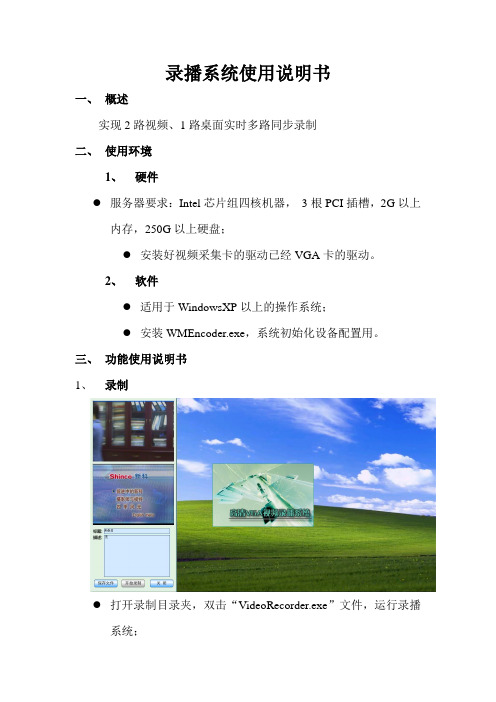
1、录制
●打开录制目录夹,双击“VideoRecorder.exe”文件,运行录播
系统;
●输入标题名及多媒体文件的描述;
●点击“保存文件”按钮,选择录制文件的路径;
●点击“开始录制”按钮即可开始录制,录制后文件名以标题为
首字符的4个文件;
●如果要结束录制,则点击“关闭”按钮即可
2、回放
●双击“播放”目录夹下的“Player.exe”,运行播放器;
●点击“播放”按钮,选择要回放的文件;
●点击“暂停“按钮即可暂停视频文件;
●点击“关闭“按钮即可关闭播放器。
录播系统操作手册
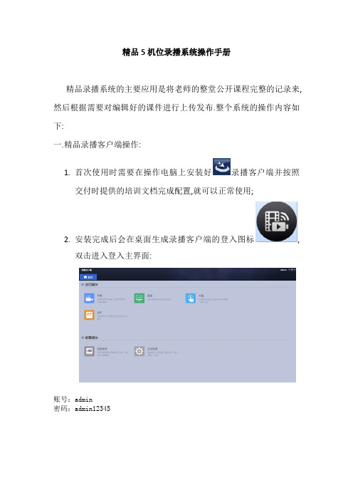
精品5机位录播系统操作手册精品录播系统的主要应用是将老师的整堂公开课程完整的记录来,然后根据需要对编辑好的课件进行上传发布.整个系统的操作内容如下:一.精品录播客户端操作:1.首次使用时需要在操作电脑上安装好录播客户端并按照交付时提供的培训文档完成配置,就可以正常使用;2.安装完成后会在桌面生成录播客户端的登入图标,双击进入登入主界面:账号:admin密码:admin123452.1 导播导播功能可对某一教室的实际课程教学过程,进行教师、学生、电脑屏幕课件等内容的综合录制。
点击,进入导播页面,界面右侧是教室信息,双击已关联了高清录播一体机的某个教室,进入导播预览界面,如下图:在此界面可以通过新建课程按钮来新建一堂课程,添加课程基本信息.配置完成进入以下画面:右上方会出现课程的信息内容,此时就可以通过界面下方的开始按键开启录制功能.课程完成后通过结束按钮来结束录制.导播预览画面的右侧,显示导播操作按钮,包括模式切换、云台控制、预置点调用、图标叠加、字符叠加等.导播预览包含三种录制模式,分别是:电影模式、画中画模式和资源模式。
当导播方式为“手动”时,可以对三种录制模式进行手动选择。
双击下方的小窗,可以切换到大画面显示。
中间云台控制主要包括各个方向的控制按钮,变倍等,实现对当前控制通道的云台控制。
注:云台控制需要在手动导播模式下控制。
预置点调用:可以选择事先设置好的预置点,设置当前控制通道的预置点。
注:预置点调用需要在手动导播模式下设置。
导播模式:右边的操作栏中,点击开关调节自动/手动导播模式。
课程延录提醒快下课时,会弹出“是否继续录制课程”的课程延录提醒。
如下图:如果老师希望拖堂,可以选择是,课程将会继续录制到下个课程开始前;如果老师不拖堂,可以选择否,就会按照课程计划的时间停止录制。
注:延录提示会在课程结束之前,具体提示时间可以在“业务配置”中“其他配置”的“录播延录时长”中进行配置。
精品五机位的录播画面如下:导播窗口左边显示2个画面,分别为VGA(课件)、板书,底部显示4个画面,分别为:教师近景、教师全景、学生近景、学生全景。
录播服务器操作手册

声明此为A级产品。
在生活环境中。
该产品可能会造成无线电干扰。
在这种情况下。
可能需要用户对其他干扰采取切实可行的措施。
本文档的任何部分,包括文字、图片、图形等全部属于我公司所拥有。
任何个人或团体在没有得到我公司书面同意的情况下,均不能以任何方式复制本文档的任何部分。
我公司本着对用户负责的态度,细心地编写该手册,但不保证本手册的内容完全正确无误。
因为我们的产品会不断地进行改良,所以我们保留对此手册修改的权利,恕不另行通知。
责任本公司对软硬件产品仅提供有限责任保证,对于由于软硬件的设计缺陷导致的用户的任何损失,本公司最高将按照购买产品的合同标的中标明的价格进行赔偿。
商标本手册中描述到的产品名称仅做识别之用,而这些名称可能属于其它公司的注册商标或是版权,在此声明如下:VRS™, MRS™, TRS™,AVX-BOX1000,AVX-BOX2000为VIDEOCON®录播产品的简称。
Pentium III、C为英特尔公司的注册商标Windows为Microsoft公司的产品注册商标。
其他商标为其相应公司所有。
版本VRS™& MRS™& TRS™ Series Revision 2.0.41 Aug 2008适用于VRS™& MRS™& TRS™V1.36以上版本目录目录 (1)前言 (3)1、系统的安装 (4)1.1、准备工作 (4)1.2、设备安装 (4)1.3、设备连线 (5)2、系统的管理 (6)2.1、串口管理 (6)2.1.1、概述 (6)2.1.2、线缆连接 (6)2.1.3、启动终端仿真软件 (6)2.1.4、串口的参数配置 (7)2.1.5、仿真软件登陆 (7)2.1.6、获得帮助 (8)2.1.7、查看服务器地址信息 (8)2.1.8、设置服务器IP地址 (8)2.1.9、设置管理员密码 (9)2.1.10、退出登陆 (10)2.1.11、重启或关闭系统 (10)2.2、系统配置 (11)2.2.1、启动管理中心 (11)2.2.2、连接服务器 (12)2.2.3、登陆服务器 (12)2.2.4、主管理界面说明 (13)2.2.5、为服务器设置IP地址 (15)2.2.6、将服务器注册到一gatekeeper上(仅VRS适用) (16)2.2.7、账号管理 (17)2.2.7.1、添加用户 (18)2.2.7.2、删除用户 (19)2.2.7.3、修改用户 (19)2.2.8、设置终端资源列表1 (19)2.2.8.1、添加终端 (20)2.2.8.2、删除终端 (21)2.2.8.3、修改终端信息 (21)2.2.8.4、导出终端列表 (21)2.2.8.5、导入终端列表 (21)2.2.8.6、将终端资源列表导入到当前入会列表 (21)2.4、节目录制 (23)2.4.1、概述 (23)2.4.2、录制参数的设定 (25)2.4.3 建立连接 (28)2.4.4、由管理器发起录制 (29)2.4.5、由H.323终端发起录制(仅适用VRS) (31)2.4.6、点对点录制(仅适用VRS) (33)2.4.6.1、从终端入会 (33)2.4.6.2、从管理器入会 (34)2.4.7、命名规则 (36)2.4.8、片头信息设置(仅适用MRS与TRS) (37)2.5、存档节目修改 (37)2.6、Web内容管理 (38)2.6.1、概述 (38)2.6.2、用户登陆 (38)2.6.3、存档节目 (38)2.6.4、直播节目 (39)2.6.4.1、概述 (39)2.6.4.2、原始码流直播 (40)2.6.4.3、ASF码流的直播 (40)2.6.4.4、资源直播(仅适用TRS) (41)2.6.4.5、两者直播之间的比较 (42)2.6.5、点播节目 (42)2.6.5.1、ASF文件的点播 (42)2.6.5.2、节目资源点播(仅适用TRS) (43)2.6.5.3、原始码流文件的点播 (45)2.6.6、插件安装 (45)2.6.7、密码更改 (46)2.6.8、web账户管理 (47)2.6.8.1、概述 (47)2.6.8.2、新增用户 (47)2.6.8.3、属性修改及节目分配 (48)2.6.8.4、用户属性预览 (49)2.6.8.5、删除用户 (49)2.6.8.6、搜索用户 (50)2.6.9、节目备份策略 (51)2.6.9.1、概述 (51)2.6.9.2、备份策略 (51)2.6.10、节目上传 (52)2.7、终端回点节目(仅适用VRS和H.323终端连接时) (54)2.7.1、概述 (54)2.7.2、终端回点 (54)3、设备更新 (56)4、附录 (57)A-存储空间不足时警告 (57)B-互联网地址 (58)C-Internet访问检查设定 (58)前言本手册为管理、使用,和安装创视通录播系列设备提供了详细安装指导和使用说明。
录播系统使用手册

3.2、普通用户收看直播
使用有直播权限的普通用户登录设备。 点击“接收直播”,浏览器将打开新的直 播播放器页面,收看直播。
3、3 录制
3.3.1 Web界面上进行快速录制 使用admin登录设备。 点击菜单栏“直播/录制”,进入设备直 播/录制管理界面。在“设备信息管理”中, 勾选要录制栏下面的音视频源。点击“快速 录制”,稍后几秒,设备即开始录制,录制 的多媒体文件以日期和时间命名,格式为 yyyyddmmhhmmss_H(即4位年份、2位月 份、2位日期、2位小时、2位分钟、2位秒 钟,_H表示高码流录制,_L表示低码流录制)。 录制时不能改变要录制的音视频源及其属性。
开机后面板
电 脑 电 源 开 启
(2)、开关投影仪
轻按面板上的“投影”按钮一下, 投影机会自动开机,约等10秒左右,电 子白板上显示电脑信号。当下课时,请 再次按“投影”按钮,5秒后即可关闭投 影机。
按 投 影 仪 键 开 关 机
切按 换电 信脑 号键 或 展 台 键
(3)、切换电脑与展台信号 轻按面板上的“展台”按钮一下, 电子白板上显示展台信号,再轻按“电 脑”按钮可切换到电脑信号。
在高级录制中,可以设置预约录制任务。预约录 制可以定时,以及设置每天、每周、每月的定时循环 录制任务。 在预约录制中可以“新增”录制,还可以进行 “修改”、“删除”等操作。
4.4.1 Web界面上停止录制
使用admin登录设备。 点击菜单栏“直播/录制”,进入设备直播/录制管理界 面。录制状态时,“开始录制”按钮变为“停止录 制”,点击“停止录制”,稍后几秒,录制即停止。
在“网存设置”栏,勾选“启用网存”。 输入网存的IP地址。如果需要将录制文件优先存储在网 存上,则勾选“优先存储网存”。点击“保存”。
HD无线监控系统快速参考指南说明书

Quick Reference GuideL222A8_QRG_EN_R12 / 2• Upgrade your recorder firmware and mobile app to the latest versions. • Please note that an upload speed of 3.5Mbps is required for remote video streaming. Up to 3 devices may connect to the system at the same time.• Ensure you have completed initial setup of the Lorex Cirrus app and the recorder as detailed in the Quick Connection Guide .Main menuSelect channels for live viewing from all connected devices Configure settings forselected channelsCast to yourmonitorAirPlay to your monitorDate and timestampBattery strength indicator Wireless signal strength indicatorDevice - Channel nameTap to activate sirenTap to activate white lightSplit-screen optionsSave a snapshot of the current liveviewTap to enable thecamera’s intercom; tap again to stopTap to start manual recording; tap againto stopSet to full HD video qualityTap to switch between muted and unmutedTap, then tap Set search options for playback:Video timeline:Tap to start playback from the selected time. Pinch or spread fingers to change the time period.Tap, then tap Configure the following as needed:Device Name: to begin playback.Tap a recorder to reveal availableand resolution.Playback time Slower Play / Pause Faster Next Frame Stop SnapshotManual RecordingMute / UnmuteYou can use playback mode in portrait or landscape mode. Landscape mode is 03/11/2020Lorex Cirrus: Camera SettingsChange camera settings using the Lorex Cirrus app.To change camera settings:Launch the Lorex Cirrus app.Tap a channel in Live View to select it.Tapto open settings for the selected channel.Configure the following as needed:Channel Name: Enter a name of your choicefor the channel (e.g., Porch Camera ).Record Length: Set the recording lengthwhen motion is detected.aL222A8_QRG_EN_R1Recorder: Initial Setup Wizard1. Log in using the system user name (default: admin ) and your new, securepassword you recorded on the Quick Connection Guide.3. Click the arrow keys to select alanguage for the on-screen display. Click Next to confirm.5.Enter the date and time:6. Review the information you have set for the recorder. Click Acceptto confirm.Click to select the correct date from the calendar.Select the correct time zone from the dropdown.Select a time format from the drop-down. For 12Hour format, select either AM or PM from the second dropdown.Click Nextto confirm.For users who wish to use the recorder’s interface rather than connecting to the system using the Lorex Cirrus app, you will have to complete the Recorder Setup Wizard to confirm the correct date and time for the system.To complete the setup wizard:2. The Setup Wizard launches.Click Next to begin.4. Click the arrow keys to select your region.Click Next to confirm.Recorder: Quick MenuRight-click anywhere on the live viewing screen to open the Quick Menu.Recorder: Search and PlaybackSearch for and play back video recordings on the DVR.To play back recorded video:1. From live view, right-click and then click Playback .2. Log in using the system user name (default: admin ) and your new, securepassword you recorded on the Quick Connection Guide .3. Use the calendar on the left-side of the screen to select the date to playback.4. Check off the channels you would like to search for recordings from on the leftside of the screen.5. Clickto search for recordings.6. Search results appear as thumbnails. Double-click any recording to begin videoplayback.Select the day to playback Select channels to playbackDouble-click any event to begin playbackClick to search for recordingsRecorder: Using the Mouse1. LEFT -CLICK:• During split-screen display mode: Double-click an individual channel to view it in full-screen.Double-click again to return to the split-screen display mode. • While navigating menus: Click to open a menu option. 2. RIGHT -CLICK: • During live view:Right-click anywhere on the screen to open the Quick Menu. • While navigating menus: Right-click to exit menus.12NOTE: In live view, hover the mouse cursor over the top of the screen to open the Navigation Bar. Move the mouse cursor away from the top of the screen to close the Navigation Bar.33. SCROLL WHEEL:• While navigating menus:Scroll to move up / down through the menu content.a bcedscreen appears. Select a filetype for your backup files, then clickThe USB flash drive contents are shown on screen. Navigate to the location youwant to save the backup files in, then click OK to begin the back up. Progress is Recordings that fit the search are shown on screen.Check recordings you want to back up, then click Backup .Search for and play back recordings.Select camera / live display view.Open the Main Menu.Back up video recordings or snapshots to a USB flash drive (not included).Do not disconnect the USB flash drive until the backup is complete.。
HDAVS摄像头用户手册说明书

HDAVS Camera User’s ManualVersion 1.0.1Table of Contents1General Introduction (1)1.1Overview (1)1.2Features (1)2Framework and Dimensions (2)3Installation (6)4Menu (9)4.1HAVR Settings (9)4.1.1Control Coaxial Device (9)4.1.2Set Audio Coax (9)4.2Menu Operation (10)Appendix Maintenance (12)WelcomeThank you for purchasing our HDAVS camera!This user’s manual is designed to be a reference tool for your system.Please read the following safeguard and warnings carefully before you use this series product!Please keep this user’s manual well for future reference!Important Safeguards and WarningsElectrical safety•All installation and operation here should conform to your local electrical safety codes.•The power shall conform to the requirement in the SELV (Safety Extra Low Voltage) and the Limited power source is rated DC 12V or AC24V in the IEC60950-1. (Power supply requirement is subject to the device label).•Please install easy-to-use device for power off before installing wiring, which is for emergent power off when necessary.•Please check if the power supply meets the requirements of working voltage of the camera before operating the device (The material and length of the power supply cable will influence terminal voltage value).•Please prevent the line cord from being trampled or pressed, especially the plug, power socket and the junction from the device.Environment•Please don’t aim the device at strong light (such as lighting, sunlight and so on) to focus. •Please transport, use and store the device within the range of allowed humidity and temperature. •Please do not allow water and other liquid falling into the camera in case that the internal components are damaged.•Please keep the sound ventilation in case of heat accumulation.•Heavy stress, violent vibration or water splash are not allowed during transportation, storage and installation.•Please pack the device with standard factory packaging or material with same quality when transporting the device.•It is recommended to use the device together with lightning protection device to enhance lightning protection effect.•It is recommended to GND the device to enhance device reliability.•It is advised to use qualified video transmission cable to improve video quality. It is recommended to use 75-3 coaxial cable or higher standard.Warning•Please use the standard accessories provided by manufacturer and make sure the device is installed and fixed by professional engineers.•Please prevent the device surface from the radiation of laser beam when using laser beam device. •Please do not provide two or more power supply modes for the device, otherwise it may cause damage to the device.Statement•Please refer to the actual product for more details; the manual is just for reference.•The manual will be regularly upgraded according to the product update; the upgraded content will be added in the manual without prior announcement.•Please contact the customer service for the latest procedure and supplementary documentation. •The company is not liable for any loss caused by the operation which is not followed by the manual. •Please refer to the company’s final explanation if there is any doubt or dispute.1General Introduction1.1OverviewThis series megapixel HD camera conforms to the HDAVS standard. It supports video signal high-speed long distance transmission without any delay. It can be controlled by the HAVR conforming to the HDAVS1.2Features●High-performance CMOS image sensor, megapixel definition.●Support HD video and control signal coaxial transmission.●Support 75-3 coaxial cable transmission without any loss. 720P series transmissiondistance over 800m, 1080P series transmission distance over 500m.●High speed, long distance real-time transmission.●Support HDAVS HD and analog SD output.●Support 3D noise reduction, excellent low illuminance performance.●Support ICR switch to realize monitoring both in daytime and at night.●Support WDR (Some models only supports DWDR).●Support OSD menu to adjust parameters.●Support smart IR function.●Support DC 12V/AC 24V power supply (AC 24V is only supported by some models).●IP67 compliance.●It can be applied to the places with HD image request, such as bank, supermarket,telecom, government, school, airport, factory, hotel and etc.2Framework and DimensionsSee Figure 2-1 for the dimension of model A. The unit is mm.Figure 2-1See Figure 2-2 for the dimension of model B. The unit is mm.Figure 2-2See Figure 2-3 for the dimension of model C. The unit is mm.Figure 2-3See Figure 2-4 for the structure components of model A and B.See Figure 2-5for the structure components of model BFigure 2-5See Figure 2-6 and Figure 2-7 for the structure components of model C.Figure 2-6Refer to Sheet 2-1 for more details about cable port. Cable colorPort name FunctionGreenALARM_NOOn-off alarm output port Orange ALARM_NC On-off alarm output port Red ALARM_IN Alarm signal input port Black ALARM_GNDAlarm signal input GND port -Audio input portExternal audio source input. Note:● It needs to set the camera “Audio Mode” as “ExternalAudio “when using external audio source input. ● External audio source has to be analog audio.- Power input portInput DC12V/AC 24V.- Analog video output port Output analog SD video signal - Video port SDIOutput digital HD video signal-HDAVS video output port Coaxial transmission of video, audio signal, it needs to connect to back-end HAVR to control.Sheet 2-1Note:When using 5-direction button to operate OSD menu, the left and right buttons fail to realize vari-focal and zoom function, then it needs to exit OSD menu and operate it again.Figure 2-8Note:Camera models with dual power use the cable structure shown in Figure 2-8; the power input port supports DC12V/AC24V power supply.Figure 2-9Note:There is only one video port for some cameras, which is shown in Figure 2-9, it outputs HD video signal by default, it needs to enable self-adaptation function in the OSD menu to switch to standard definition video signal.3InstallationImportant●Please install the device in time after it is taken apart, which is to avoid the cameramodule being exposed to damp environment for too long.●Before the installation, please make sure the installation surface should be thickenough to sustain at least 3X weight of the camera.Step 1Take out the installation position map from the accessories bag, stick it on the ceiling or wall according to the cable exit, dig holes on the installation surface according to the installation position map, and see Figure 3-1. Pull out the camera cable through the cable exit on the bracket pedestal, and install camera bracket.Figure 3-1●If it is cement wall, it needs to install expansion bolt first (the installation holes ofexpansion bolt need to be in accordance with bracket), then use self-tapping screws to install bracket.●If it is wooden wall, you can just skip the first step, use self-tapping screws to installbracket directly.Step 2 Adjust the camera monitoring direction●If it is the model c or c (1), then use the L-shaped wrench in the accessories bag to loosenthe adjusting screws, adjust the camera to the specific direction which needs to bemonitored, then use L-shaped wrench to tighten adjusting screws and fix the camera, see Figure 3-2.Figure 3-2●If it is model a or model b, then loosen the M3 X 20 and M3 X 5 screws on the bracketaccording to the direction shown in Figure 3-3, adjust the camera to specific monitoring direction via rotating bracket and camera body, then fix the screws.Figure 3-3Step 3Connect the video output port of device cable to the back-end HAVR device, and connect power port to power supply.Step 4 Adjust camera zoom and focus●If it is the model a, then it needs to adjust lens zoom and focus on the back-end HAVRdevice to make the image clear.If it is the model b, after displaying image on the back-end HAVR device, open the camera lower cover and adjust lens focal length via focus/zoom lever to make image clear, and then tighten the lever. Retighten the camera lower cover and complete camera installation.Note:The installation figures above are for reference only.4Menu4.1 HAVR Settings4.1.1 Control Coaxial DeviceThis HDAVS camera series can adjust OSD menu via coaxial control. After connected the camera to the HDAVS series HAVR, from Main Menu->Setting->System->PTZ, you need to select the channel number for access and set control mode as HDAVS and the protocol asHD-AVS. Click “Save” button to save current setup. See Figure 4-1.Figure 4-14.1.2 Set Audio CoaxFrom “Main Menu > Setting > Camera > Encode > Encode”, you need to set “Audio Format” as “G711a” and the “Audio Source” as “HDAVS”. See Figure 4-2 for more details.Figure 4-24.2 Menu OperationClick the right mouse button and select “PTZ Control”, then you will see the “PTZ Setup” menu,which is as shown in Figure 4-3 and Figure 4-4.Figure 4-3Figure 4-4See Sheet 4-1 for the details of button functions.ButtonFunctionOpen menu 、Select menu item 、 Select menu valueAdjust lens zoom and auto trigger focus Note: Some of the buttons can only be applied for the motorized vari-focal camera.Adjust lens focusAuto focus under current zoom rate Lens resetSheet 4-1 If there is “”, click the “Confirm” button in “Menu Operation” interface to go to the 2nd menu. Click “Return” button to go back to the previous menu interface.Appendix MaintenanceAttention:Please maintain the device according to the following instructions in order to ensure the image effect and long-term stable operation of the device.Maintenance for lens and mirror surfaceThe lens and mirror surface are covered with antireflection coating, so it may produce hazardous substance and lead to performance reduction or scratch, dimness etc when it is stained with dust, grease, fingerprint and so on, please refer to the following methods to deal with once dirt is found:Stained with dirtUse oil-free soft brush or hair dries to remove it gently.Stained with grease or fingerprintUse soft cloth to wipe the water drop or oil gently to make it dry, then use oil-free cotton cloth or paper soaked with alcohol or detergent to wipe from the lens center to outward. It is ok to change the cloth and wipe several times if it is not clean enough.Camera Body MaintenanceUse a soft dry cloth to clean the camera body when it is dirty, in case the dirt is hard to remove, use a clean dry cloth soaked with mild detergent and wipe gently, make it dry later. Don’t use volatile solvent like alcohol, benzene, thinner and etc or strong detergent with abrasiveness, otherwise it will damage the surface coating or reduce the working performance of the device.Maintenance for Dome CoverDome cover is an optical device, please don’t touch or wipe cover surface directly during installation and use, please refer to the following methods to deal with once dirt is found:Stained with dirtUse oil-free soft brush or hair dries to remove it gently.Stained with grease or fingerprintUse soft cloth to wipe the water drop or oil gently to make it dry, then use oil-free cotton cloth or paper soaked with alcohol or detergent to wipe from the lens center to outward. It is ok to change the cloth and wipe several times if it is not clean enough.Note•This manual is for reference only. Slight difference may be found in the user interface.•All the designs and software here are subject to change without prior written notice.•All trademarks and registered trademarks mentioned are the properties of their respective owners.•If there is any uncertainty or controversy, please refer to the final explanation of us.•Please visit our website or contact your local service engineer for more information.。
DVR-HD8S 8通道高清SDI视频录像机说明书

DVR-HD8S8C h a n n e l2U H D-S D I V i d e o R e c o r d e r The New HD-SDI series - Real-time recording at 960 resolution, plus synchronized audio on every channel.These DVRs are designed to provide an extremely high resolution at 720i. With the ability to provide H264E Realtime recording across all channels, the DVR incorporates an HDMI interface delivering high definition 1080i resolution images that provide remarkable crisp clear pictures of depth and definition. The unique feature of these systems is delivery and recording true high definition video stream through the existing CCTV coaxcables.Features∙Support 8 SATA HDDs up to 32TB, 1 eSATA up to 16TB, 3 USB2.0∙Built-in web server, SmartICRSS, ICRSS Pro & ICVIEW∙Smart video detection: MD, camera blank, video loss∙3D intelligent positioning with ICR PTZ dome cameras∙Easy backup: USB devices, CD/DVD-RW & network download ∙Alarm triggering screen tips, buzzer, PTZ, e-mail & FTP upload∙Up to 8 channel 1080P cameras realtime preview∙8 channel simultaneous realtime playback, GRID interface & smart search∙HDMI / VGA / TV (BNC) synchronous video output∙8 channel@1080P realtime recording∙>H.264 dual-stream video compressionRevision 1.2; 11/2015∙8 channel HD-SDI 1080P standalone DVR ∙Dual-core CPU allows powerful preview, recording, playback and networkperformance ∙8 channel 1080P (30fps) / 1080i (60fps) / 720P (30/60fps) HD-SDI video inputsDVR-HD8S SpecificationsIC Realtime LLC3050 N Andrews Avenue ExtensionPompano Beach, FL 33064(866) 997-9009Designs and specifications subject to change without notice. Copyright © 2015 IC Realtime, LLC. All rights reserved.。
DVR硬盘录像机操作说明汇总

DVR硬盘录像机操作说明1、开机插上电源线,按下后面板的电源开关,电源指示灯亮,录像机开机,开机后视频输出默认为多画面输出模式,2、关机进入【主菜单】→【关闭系统】中选择【关闭机器】(△注:关机时建议使用此方式,以避免意外断电时对设备造成损害。
3、进入系统菜单正常开机后,系统会自动弹出开机向导提示,点击“取消”进入系统登录界面,点击“下一步”则进入开机向导设置界面。
选择开机向导后可直接进入常用功能界面进行设置,包括:基本设置、输出设置、编码设置、录像计划、录像控制和网络设置进入登录系统对话框时,用户在输入框中输入用户名和密码。
说明:出厂时有4个用户admin、888888、666666及隐藏的default。
前三个出厂密码与用户名相同。
admin、888888出厂时默认属于高权限用户,而666666出厂默认属于低权限用户,仅有监视、回放、备份等权限。
密码安全性措施:每30分钟内试密码错误3次报警,5次帐号锁定。
4、预览设备正常登录后,直接进入预览画面。
在每个预览画面上有叠加的日期、时间、通道名称,屏幕下方有一行表示每个通道的录像及报警状态图标(各种图标的含义见下表)通道画面提示:预览放大功能:当使用鼠标时,鼠标移动到预览画面左上角会出现预览放大图标,鼠标左键单击该图标,图标显示打当使用鼠标时,鼠标移动到预览画面左上角会出现预览放大图标,鼠标左键单击该图标,图标显示打钩,表示开启放大功能。
此时用鼠标在预览画面拖动可放大该区图像。
5、录像查询回放►/=管理电脑软件操作说明1、双击桌面上的“PSS”图标,弹出系统登录界面如下:用户名:程序登录的授权用户名;密码:对应用户登录时的密码;保存密码:保存最后一次有效登录的用户名和密码信息,下次登录时可不用输入用户名和密码;确定:验证用户名和密码,进入程序界面;取消:取消登录,退出程序。
2、输入正确的用户名和密码,单击确认,系统验证用户名和密码后进入初始化进度界面3、主界面系统初始化完成后即进入PSS 系统主界面。
洛雷X HD数字视频监控录制器系统用户手册说明书

Copyright © 2019 Lorex CorporationAs our products are subject to continuous improvement, Lorex reserves the right to modify product design, specifications and prices, without notice and without incurring any obligation. E&OE. All Quick Start GuidesUSB MousePower CableEthernet Cable HDMI CableNeed Help?Visit us online for up-to-date software andcomplete instruction manualsClick on the Downloads tabVisit Search for the model numberof your product Click on your product in thesearch resultsDouble-clickan individual channel to view it in full-screen. 12Click inside the video bar to select the playback time to begin playback.LHA4000_LS_QCG_EN_R2System InformationTo quickly open a window that displays vital system information such as device ID, firmware version, and IP address:From live view, clickat the bottom of the screen.3Presson the included remote control.If prompted, enter the system user name (default:) and your new, secure password recorded in the section ‘DVR Setup Wizard’.ORReview the information you have set for the DVR. To confirm, click Accept .Enter the date and time:Click to select the correct date from the calendar.Click to enter time using the on-screen keyboard.Select a date format from the dropdown.Select a time format from the dropdown. 12Hour format, select either AM or from the second dropdown.Next to confirm.。
杭州阿尔卡特 EV5000系列DVR DVS 产品技术手册
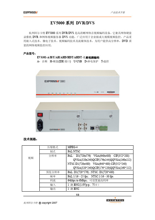
1/3EV5000系列 DVR/DVS杭州阿尔卡特EV5000系列DVR/DVS 是高清晰网络音视频编码设备。
它兼具网络硬盘录像机DVR 和网络视频服务器DVS 功能,广泛应用于企业级或大规模视频监控。
产品采用嵌入式技术、微电子技术、视频编码技术及流媒体技术,为用户提供高分辨率,DVD 质量的网络视频监控应用。
产品型号:EV5301-A/H/U/AH/AHD/HDT/AHDT -1路视频编码A- 音频 H-硬盘(IDE 接口) U-USB D-掉电保护 T-温控技术规格:压缩格式 MPEG-4制式 PAL/NTSC分辨率 PAL: D1(720x576) VGA(640x480) CIF(352*288) QVGA(320x240)QCIF(176x144)QQVGA(160x112)NTSC:D1(720x480) VGA(640*480) CIF(352*240) QVGA(320*240)QCIF(176*120)QQVGA(160*112)预览分辨率 PAL: D1(720*576) ; NTSC: D1(720*480) 帧率 PAL:1/16—25 fps; NTSC:1/16—30 fps码流 64kbps to 6Mbps ,可设置最高码率 输入 1 路BNC(1.0Vp-p ,75Ω)视频输出 1 路BNC2/3压缩格式 ADPCM,16bit 采样率 8khz输入 1 路 BNC (2.0 Vp-p,1K Ω)音频 输出 1 路 BNC (600Ω)1 个RJ45 10/100M 自适应网络接口 1 个RS-485 口通讯口4 路告警输入或4路控制输出USB 1 个USB2.0接口接口 IDE 2 个IDE 接口,支持4个硬盘,每个硬盘最大320G电压 220V 频率 50Hz 电源功耗 30W (含2个硬盘) 温度 -20℃~55℃ 湿度 20%~80%尺寸((L*W*H) 330*220*90mm尺寸工作环境 重量 3.3KG (无硬盘)产品特性:基本特性----高性能嵌入式ARM 处理器----嵌入式实时LINUX 操作系统----高性能DSP 硬件压缩----RTSP 流媒体协议音视频编码----支持MPEG1/2/4压缩标准----支持多区域动态侦测----码率, 帧率可调----支持I/P/B 帧,帧率可调----带宽1.5M 以上,具有DVD 画质,FULL D1分辨率图象----支持窄带40 Kbps QCIF 视频品质----OSD 显示功能,中文英文支持,8种时间显示格式,设置显示内容存储功能----带2个IDE 接口,支持4个硬盘,每个硬盘最大支持320G----支持FAT32/EXT2/EXT3/NFS 文件系统----支持多种录像模式,全时/手动/外部告警/移动侦测----支持循环和非循环录像----支持本地硬盘存储,存储方式可通过WEB设置,并显示硬盘空间信息----支持远程存储功能-可配置存储服务器,集中存储音视频数据。
AVST AT1016 16 CH 720P A-HD DVR系统说明书

Back
AVST AT1016 is standard 16 CH real time 720P high resolution DVR, which adopt the standard H.264 high profile compression format and the most advanced SOC technique to ensure real time recording in each channel and realize outstanding robustness of the system. AVST AT1016 support 16 CH video input, 1 CH audio input, simultaneous 16 CH real time playback. The series of product can meet different security requirements of home, financial, commerce, enterprise, transportation and government, etc.
Specifications may change without a prior notice. All the images on the page are for illustrative purpose only. They may not representing actual products. All the rights for the registered trademarks are reserved for their respectable owners. Not responsible for any typographical errors.
高清录像服务器使

高清录像服务器使用指南1、安装服务介绍运行rpm -ivh RecordSvr-1.0-1.i386.rpm 安装流媒体服务器成功安装后会提示“RecordSvr has been installed successfully!2、软件目录介绍+/usr/local/Tvlink/RecordSvr-1.0-1 //+录像服务器安装目录|---+bin //|---+应用程序目录|---Recorder // |---录像服务器应用程序|---Daemon // |---录像服务器守护程序|---RunRecord // |---启动录像服务器脚本|---RunDisk // |---启动存储服务器脚本|---Loggerc // |---录像服务器日志配置文件|--- ulimit.sh // |---修改系统限制脚本|---+DiskSvr // |---+存储服务器目录|--- DiskSvr // |---存储服务器应用程序|---DiskDaemon // |---存储服务器守护程序|---Loggerc // |---存储服务器日志配置文件|---+config //|---+配置文件目录|--- Config.ini // |---配置文件|---+lib //|---+动态库目录|---*.* // |---动态库|---+doc //|---+说明文档|---readme // |---配置文件说明|---+log //|---+日志目录|---+DiskSvr // |---+存储服务器日志目录|---+RecordSvr // |---+录像服务器日志目录|---readme //|---目录说明3、配置文件介绍运行服务器前请根据运行环境修改配置文件:编辑/usr/local/Tvlink/RecordSvr-1.0-1/config/Config.ini,进行参数配置,修改后保存配置文件。
- 1、下载文档前请自行甄别文档内容的完整性,平台不提供额外的编辑、内容补充、找答案等附加服务。
- 2、"仅部分预览"的文档,不可在线预览部分如存在完整性等问题,可反馈申请退款(可完整预览的文档不适用该条件!)。
- 3、如文档侵犯您的权益,请联系客服反馈,我们会尽快为您处理(人工客服工作时间:9:00-18:30)。
2.2.1 概念介绍
1、超级用户 root:root 用户是录播服务器的超级管理员,它可以使用录播服务 器的所有功能,特别是只有它可以管理用户组; 2、组:由于录播服务器支持并发、独立的录制,组就被用来划分独立的录制任 务,以及相应的单播、点播、组播等资源; 3、组管理员:每个组都有至少一个组管理员,用来管理组内用户、录制模板和 文件等资源; 4、组用户:组用户是一般用户用来收看单播、组播和点播的,它不能管理录制 任务和文件等资源。
严禁在修改 IP、升级过程中断电、断网。
第3页
Aethra DVR-HD 高清录播服务器用户手册
第2章 系统使用
2.1 系统页面登陆
LeadMeet 系列产品中的 H.323 录播服务器使用 Web 界面进行管理、使用。 该套系统支持 IE、Firefox 等主流浏览器。默认 Web 端口 80。
第2页
Aethra DVR-HD 高清录播服务器用户手册
第1章 产品配置
1.1 设备的 IP 地址配置 首先将设备放置在会议室或控制室相应的机柜上; 将电源线接入设备电源插口,将网线连接到配置网口(机器下方),按下
电源开关;如图:
在客户端的 PC 机增加一个 IP 地址:10.10.10.x(x 为除 10 以外的 1~254 之间的任意一个数字),子网掩码为 255.255.255.0。
第5页
Aethra DVR-HD 高清录播服务器用户手册
2.2.3 用户管理
图 2-2
超级用户 root 以及每个组的管理员可以管理用户。在 击“添加用户 …”,出现下图所示窗口:
页面中,点
图 2-3 在用户名和密码中填入相应数据,并选择所属组,确定是否是组管理员,点 “添加”提交。 在用户列表中点击“删除”就可以删除某用户。 每个用户都可以在“当前用户信息”中更改密码,如下图所示:
启动 IE 浏览器,在地址栏中输入 URL:http://10.10.10.10:800(端 口号必须输入),进入 DVR-HD 的登录页面,输入用户名和密码(初始值
为 admin 和 1234)。登录后进入网络下的
菜单,修改使用网口
的 IP 地址、子网掩码和默认网关,然后点击确定(Submit),重新启动系 统。(注:系统启动成功时会伴有一次“滴滴滴滴滴”五声急促短鸣,启 动时间大概为 1 分钟)。
2.2.2 用户组管理
超级用户 root 登录系统后,点击 用户组管理界面:
,点击“添加组 …”,右侧出现
图 2-1 填入组名称后点击“添加”,该组就被添加,并显示在下方列表中。如图 2-1 所 示,该系统当除某个用户组,可以点击某个用户组,点击删除,如下图所示:
地址配置完成后,将上面网口接入交换机即可开始使用 DVR-HD。
1.2 使用注意事项
系统默认的管理员用户名不能修改,密码建议您在使用时进行修改,但 必须妥善保存,如果密码忘记将无法登录系统,只能通过厂商技术支持恢复 DVR-HD 的出厂设置,将用户名和密码分别恢复为 admin 和 1234。
(分辨率不输入系统将自动适应终端或 MCU 发送过来的分辨率) 要使用某个模板开始录制任务,或者修改、删除模板,单击模板列表中的模 板名称,展开如下图所示:
图 2-6
第8页
Aethra DVR-HD 高清录播服务器用户手册
其中,任务名称和录制文件名称可以被用来指定某个任务的名称,和录制下 来的文件名称。
2.2.1 概念介绍...........................................................................................................5 2.2.2 用户组管理.......................................................................................................5 2.2.3 用户管理...........................................................................................................6 2.2.4 模板管理...........................................................................................................7 2.2.5 任务管理...........................................................................................................9 2.2.6 文件管理.........................................................................................................10 第 3 章 安全事项.....................................................................................................................13 第 4 章 保修服务.....................................................................................................................14 4.1 保修内容.....................................................................................................................14 4.2 售后服务方式.............................................................................................................14
AETHRA DVR-HD 高清录播服务器用户手册
(V1.3)
深圳市瑞得爱斯乐科技有限公司
Aethra DVR-HD 高清录播服务器用户手册
版权信息 版权所有 瑞得爱斯乐科技有限公司 保留所有权利。除非版权法 允许,否则,事先未经书面 许可,任何人不得进行复制、 改编、翻译或用于其它商业 目的。
声明
声明 本产品为 A 级产品,在生活 环境中,该产品可能会造成 无线电干扰。在这种情况下 可能需要对其干扰采取切实 可行的措施。
由于软硬件变化可能导致本文信息与实际情况有偏差,实际情况为准。 瑞得爱斯乐科技有限公司保留该文档的最终解释权。
第1页
Aethra DVR-HD 高清录播服务器用户手册
目录
声明 ..................................................................................................................................................1 目录................................................................................................................................................... 2 第 1 章 产品配置.......................................................................................................................3
1.1 设备的地址配置...........................................................................................................3 1.2 使用注意事项...............................................................................................................3 第 2 章 系统使用.......................................................................................................................4 2.1 系统页面登陆...............................................................................................................4 2.2 使用模式.......................................................................................................................5
文件(主流辅流分开)。 8. 码率:录制任务的码率。 9. 允许呼入:是否允许远端 H.323 终端呼入触发录制和点播任务。 10. 点播文件:播放给远端 H.323 终端的媒体文件。
第7页
Aethra DVR-HD 高清录播服务器用户手册
11. 打开音频:是否允许音频。 12. 打开视频:是否允许视频。 13. 打开双流:是否允许双流。 14. 打开 H.239:是否允许 H.239 双流。 15. 强制打开双流通道:默认关闭。 16. 打开 FECC:远摇功能。(终端点播通过终端遥控器远摇功能实现) 17. 音频编码:音频编码,Auto 为自适应。 18. 视频编码:视频编码,Auto 为自适应。 19. 双流编码:双流编码,Auto 为自适应。 20. E164:网守号码。 21. 远端地址:远端 H.323 终端 IP 地址。 22. 视频分辨率:视频分辨率,使用“,”分割,如“352x288,1024x768,1280x720” 23. 双流分辨率:双流分辨率,使用“,”分割,如“352x288,1024x768,1280x720”