ACSC02-41SEKWA-F01, 规格书,Datasheet 资料
样本 丹佛斯 电磁阀

波兰(Polski Rejestr Ststkow) 俄罗斯(MRS) 也可提供通过 UL 认证产品。
DKRCC.PD.BB0.B3.41 / 520H7191
参数表 技术数据
2
电磁阀,型号 EVR 2 − 40 NC/NO
制冷剂
R22/R407C、 R404A/R507 、R410A、R134a、R407A、 R23。如需使用其他 制冷剂,请洽询 Danfoss。
R404A/ R507 1.20 2.00 6.00 14.30 19.60 37.70 45.20 75.30 120.00 188.00
பைடு நூலகம்
液体和吸气名义制冷量的工况条件为:
蒸发温度 te = -10 °C 阀门前液体温度 tl = 25 °C 经过电磁阀压力降 ∆p = 0.15 bar
热气名义制冷量的工况条件为:
—
a.c./ d.c. 1/2 12 032F8095 032F1217 032F1218
—
a.c./ d.c. 5/8 16 032F8098 032F1214 032F1214
—
a.c./ d.c. 5/8 16 032F8101 032F1228 032F1228
—
a.c./ d.c. 5/8
—
d.c.
7/8
22
—
—
—
032F1274
a.c.
1 3/8 35
—
032F3267 032F3267
—
a.c./ d.c. 1 1/8
—
—
—
032F2200
a.c./ d.c. — 28
—
—
—
032F2205
伟肯变频器用户手册
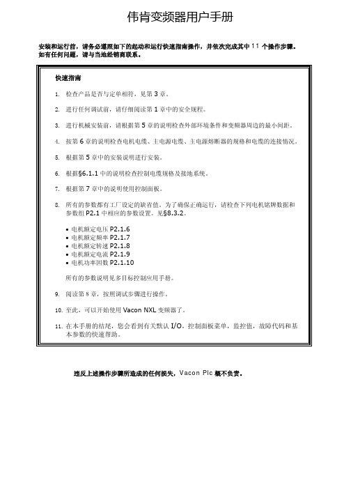
伟肯变频器用户手册安装和运行前,请务必遵照如下的起动和运行快速指南操作,并依次完成其中11个操作步骤。
如有任何问题,请与当地经销商联系。
快速指南1. 检查产品是否与定单相符,见第3章。
2. 进行任何调试前,请仔细阅读第1章中的安全规程。
3. 进行机械安装前,请根据第5章的说明检查外部环境条件和变频器周边的最小间距。
4. 按第6章的说明检查电机电缆、主电源电缆、主电源熔断器的规格和电缆的连接情况。
5. 根据第5章中的安装说明进行安装。
6. 根据§6.1.1中的说明检查控制电缆规格及接地系统。
7. 根据第7章中的说明使用控制面板。
8. 所有的参数都有工厂设定的缺省值。
为了确保正确运行,请检查下列电机铭牌数据和参数组P2.1中相应的参数设置。
见§8.3.2。
• 电机额定电压P2.1.6• 电机额定频率P2.1.7• 电机额定转速P2.1.8• 电机额定电流P2.1.9• 电机功率因数P2.1.10所有的参数说明见多目标控制应用手册。
9. 阅读第8章,按照调试步骤进行操作。
10. 至此,可以开始使用Vacon NXL变频器了。
11. 在本手册的结尾,您会看到有关默认I/O,控制面板菜单,监控值,故障代码和基本参数的快速帮助。
违反上述操作步骤所造成的任何损失,Vacon Plc概不负责。
目录VACON NXL用户手册目录1 安全指导2 EU认证3 收货4 技术数据5 安装6 电缆和接线7 控制面板8 调试9 故障跟踪10 选件卡OPT-AA的描述11 选件卡OPT-AI的描述VACON NXL多目标控制应用手册vacon • 3Vacon China电话: +86-10-51280006 传真: +86-10-65813733 24小时支持热线: +86-137******** Email :***************.cn关于VACON NXL 用户手册和多目标控制应用手册恭喜您选择了Vacon NXL 变频器所提供的平滑控制!用户手册将为您提供有关Vacon NXL 变频器的安装,调试和操作的必要信息。
ACSC02-41CGKWA-F01, 规格书,Datasheet 资料

芯天下--/
PACKING & LABEL SPECIFICATIONS
ACSC02-41CGKWA-F01
SPEC NO: DSAG0271 APPROVED: WYNEC
REV NO: V.5 CHECKED: Joe Lee
DATE: MAR/21/2011 DRAWN: J.Yu
Note: 1. Luminous intensity/ luminous Flux: +/-15%.
Electrical / Optical Characteristics at TA=25°C
Symbol λpeak λD [1] Δλ1/2 C VF [2] IR Parameter Peak Wavelength Dominant Wavelength Spectral Line Half-width Capacitance Forward Voltage Reverse Current Device Green Green Green Green Green Green Typ. 574 570 20 15 2.1 2.5 10 Max. Units nm nm nm pF V uA Test Conditions IF=20mA IF=20mA IF=20mA VF=0V;f=1MHz IF=20mA VR=5V
DATE: MAR/21/2011 DRAWN: J.Yu
PAGE: 3 OF 5 ERP: 1351000427
芯天下--/
ACSC02-41CGKWA-F01
Recommended Soldering Pattern (Units : mm; Tolerance: ± 0.15)
Description
MOGAS 产品样本

电力系统用阀苛刻工况用球阀目录阀门选型指南型号 球孔端部尺寸压力等级 阀门信息 阀体端部连接 页码(英寸)(英寸)材质.承插焊接 对焊连接 法兰连接卡箍连接现货RSVP-UK 0.38 1/2 – 3/4 ASME600 / 900 /1500限制级 • 轻型• 带安装支架的一体化设计• 单向密封F22A105F91标准 标准 可选 — 有 10RSVP-UC RSVP-UF RSVP-UL 0.631.001.303/4 – 2-1/2 ASME600 / 900 /1500限制级• 排气,疏水• 锻造一体化设计• 单向密封F22A105F91标准 标准 可选 — 有 12RSVP-UM 1.50 1-1/2, 2,2-1/2 ASME600 / 900 /1500限制级• 设计达到 TDP-1 1998标准 (热再热)• 锻造一体化设计• 单向密封F22A105F91标准 可选 可选 — — 12RSVP-UC RSVP-UF RSVP-UL 0.631.001.303/4 – 2-1/2 ASME 3100限制级• 排气,疏水• 锻造一体化设计• 单向密封F22A105F91标准 标准 可选 — 有 14RSVP-UC RSVP-UF 0.631.003/4 – 2-1/2 ASME 4500限制级• 排气,疏水• 锻造一体化设计• 单向密封F22 标准 可选 可选 — 有 16GEN-X 全通径2.001.87 2 ASME600 / 900 /1500限制级• 设计达到 TDP-1 1998标准 (冷再热)• 2件式铸体•WC9WCCC12A标准 标准 可选 — 有 18SC-3件式 2.00 2 – 6 ASME 2500 • 锅炉给水加热器, 再循环隔离, 减温器喷水隔离• 可在线维修, 3件式锻造结构• 标准2英寸管径F22 可选 标准 可选 可选 有 20ISOLATOR 全通径 2 – 8 ASME150 / 300 •灰浆• 煤浆• 底灰CF8M(316SS)— 可选 标准 — 有 22C-系列 全通径,缩径、定制 1/2 – 30 ASME 150 – 4500 • 严密隔离关断• 2件式或3件式锻造阀体构造• 单向 / 双向密封所有材质 可选 可选 可选 可选 — 24PORV 1.301.601.812.002.125 不定 ASME1500 / 2500 /4500• 压力释放阀• ASME 的“V”标志• 完全自动化控制• 专用涂层F22 — 可选 可选 — — 26SD 定制管径 依据规范 ASME 4500特殊级别 • 主蒸汽疏水,汽机旁路• 定制, 3件式设计• 单向密封F22 — 可选 — 可选 — 28执行机构所有MOGAS球阀均可根据客户的执行器规范轻松实现自动化操作。
电动密闭阀门

电动密闭阀门15日零时45分许,从事故现场传出消息:氨气泄漏点在会宾冷饮冰棍厂氨气输送管道阀门处,目前阀门已经被关闭,正在对裂缝进行堵漏。
会宾冷饮冰棍厂厂长是一位穿红色T恤衫、偏胖的男子,14时许,他发现氨气泄漏后没有及时报警求助,而是想由厂里负责处置。
看到消防官兵赶到后,他开始主动介绍厂内的基本情况,并寻求帮助。
穿上防化服的消防官兵分为几个小组,背着氧气瓶进入事故现常几分钟后,终于找到了氨气泄漏点,公安消防支队参谋长张勇带领两名消防官兵冒险将阀门关闭,其他官兵则在泄漏点附近负责警戒。
阀门被关闭后,张勇命令官兵们将打湿的棉被紧紧裹在泄漏处,采取冷却法进行堵漏。
2时50分,事故现场再次传来消息:泄漏点被完全堵住,事故险情排除。
此时,被疏散的居民有的已经躺在凉席上睡着了,一些居民抱着熟睡的孩子自己也在打盹。
听说险情排除了,居民们你叫我、我叫他,过了十几分钟就陆陆续续都回家了,大街上又恢复了宁静。
蝶阀>>对夹蝶阀>>对夹式电动软密封蝶阀产品名称:对夹式电动软密封蝶阀产品型号:D971X产品口径:DN50~1200产品压力:0.6MPa~1.6MPa产品材质:铸铁、铸钢、不锈钢等产品概括:生产标准:国家标准GB、机械标准JB、化工标准HG、美标API、ANSI、德标DIN、日本JIS、JPI、英标BS生产。
阀体材质:铜、铸铁、铸钢、碳钢、WCB、WC6、WC9、20#、25#、锻钢、A105、F11、F22、不锈钢、304、304L、316、316L、铬钼钢、低温钢、钛合金钢等。
工作压力1.0Mpa-50.0Mpa。
工作温度:-196℃-650℃。
连接方式:内螺纹、外螺纹、法兰、焊接、对焊、承插焊、卡套、卡箍。
驱动方式:手动、气动、液动、电动。
产品详细信息70 016547815345465568124-268424-38424-3680 01952511595465569224-39524-339524-3990 02035851748617706102024-3105028-33105038-3910 00216641805632706112028-3116028-36117028-4212 002547552035632706134032-33138032-39139032-48首页>>产品中心>>多回转阀门电动装置一、产品[多回转阀门电动装置]的详细资料:产品型号:Z型产品名称:多回转阀门电动装置产品特点:多回转阀门电动装置,通称为Z型。
Oxymax W COS41 溶解氧传感器说明书
Brief Operating InstructionsOxymax W COS41Dissolved oxygen sensorThese instructions are Brief Operating Instructions.For detailed information, please read the Operating Instructions and the special instructions on the supplied CD-ROM.The complete device documentation comprises:•these Brief Operating Instructions•the Operating Instructions on the supplied CD-ROM•if necessary, certificates and calibration protocols (acc. to the version).KA284C/07/en/06.0571002048Table of contents Oxymax W COS41 Table of contents1 Safety instructions. . . . . . . . . . . . . . . . . . . . . . . . . . . . . . . . . . . . . . . . . . . . . . . . . 21.1 Designated use . . . . . . . . . . . . . . . . . . . . . . . . . . . . . . . . . . . . . . . . . . . . . . . . . . . . . . . . . . . . . . . . . . . . . . . . . . 21.2 Installation, commissioning and operation . . . . . . . . . . . . . . . . . . . . . . . . . . . . . . . . . . . . . . . . . . . . . . . . . . . . . . 21.3 Operational safety . . . . . . . . . . . . . . . . . . . . . . . . . . . . . . . . . . . . . . . . . . . . . . . . . . . . . . . . . . . . . . . . . . . . . . . . 32 Installation. . . . . . . . . . . . . . . . . . . . . . . . . . . . . . . . . . . . . . . . . . . . . . . . . . . . . . 32.1 Installation conditions . . . . . . . . . . . . . . . . . . . . . . . . . . . . . . . . . . . . . . . . . . . . . . . . . . . . . . . . . . . . . . . . . . . . . 32.2 Installation instructions . . . . . . . . . . . . . . . . . . . . . . . . . . . . . . . . . . . . . . . . . . . . . . . . . . . . . . . . . . . . . . . . . . . . 42.3 Installation examples . . . . . . . . . . . . . . . . . . . . . . . . . . . . . . . . . . . . . . . . . . . . . . . . . . . . . . . . . . . . . . . . . . . . . 52.4 Post installation check . . . . . . . . . . . . . . . . . . . . . . . . . . . . . . . . . . . . . . . . . . . . . . . . . . . . . . . . . . . . . . . . . . . . 83 Wiring . . . . . . . . . . . . . . . . . . . . . . . . . . . . . . . . . . . . . . . . . . . . . . . . . . . . . . . . . 93.1 Direct connection to the transmitter . . . . . . . . . . . . . . . . . . . . . . . . . . . . . . . . . . . . . . . . . . . . . . . . . . . . . . . . . . 93.2 Connection via junction box . . . . . . . . . . . . . . . . . . . . . . . . . . . . . . . . . . . . . . . . . . . . . . . . . . . . . . . . . . . . . . . 104 Commissioning. . . . . . . . . . . . . . . . . . . . . . . . . . . . . . . . . . . . . . . . . . . . . . . . . . 114.1 Function check . . . . . . . . . . . . . . . . . . . . . . . . . . . . . . . . . . . . . . . . . . . . . . . . . . . . . . . . . . . . . . . . . . . . . . . . . 114.2 Polarization . . . . . . . . . . . . . . . . . . . . . . . . . . . . . . . . . . . . . . . . . . . . . . . . . . . . . . . . . . . . . . . . . . . . . . . . . . . 114.3 Calibration . . . . . . . . . . . . . . . . . . . . . . . . . . . . . . . . . . . . . . . . . . . . . . . . . . . . . . . . . . . . . . . . . . . . . . . . . . . . 121Safety instructions1.1Designated useThe oxygen sensor is suitable for continuous measurement of dissolved oxygen in water.Typical applications are:•Measuring, monitoring and regulating the oxygen content in activated sludge basins.•Monitoring the oxygen content in the sewage treatment plant outlet.•Monitoring, measuring and regulating the oxygen content in public waters and fish farming water.•Monitoring of oxygen enrichment in drinking water.Any other use than the one described here compromises the safety of persons and the entire measuring system and is, therefore, not permitted.The manufacturer is not liable for damage caused by improper or non-designated use.1.2Installation, commissioning and operation•The device/measuring system may only be installed, connected, operated and maintained by trained technical personnel (e.g. certified electrician). The technical personnel must strictlyadhere to the Operating Instructions, prevailing standards, legal regulations and certificates(depending on application).•If the Brief Operating Instructions do not provide sufficient information, you must read theOperating Instructions. There, you can find detailed information on the device.2Endress+HauserOxymax W COS41InstallationEndress+Hauser 3•The operator may only perform modifications and repairs of the device/measuring system that are explicitly permitted in the Operating Instructions.•Do not operate damaged products and secure them against unintentional commissioning. Mark the damaged product as being defective.•If faults can not be rectified, the products must be taken out of service and secured against unintentional commissioning.1.3Operational safetyThe sensor has been designed and tested according to the state of the art and left the factory in perfect functioning order.Relevant regulations and European standards have been met.As the user, you are responsible for complying with the following safety conditions: •Installation instructions•Local prevailing standards and regulations."Caution!Pay attention to the technical data on the name plate!2Installation2.1Installation conditions2.1.1OrientationOther angles are not permitted. Do not install the sensor overhead.Fig. 1: Angle of installation ARecommended angle of installation: 0 ... 180 °Installation Oxymax W COS414Endress+Hauser2.1.2Mounting location•Select the installation location so that there is easy access for later calibration.•Make sure that upright posts and assemblies are secured safely and vibration-free.•For immersed operation in an activated sludge basin, select an installation location which produces a typical oxygen concentration.2.2Installation instructions2.2.1Installing a measuring point!Note!For immersed operation, install the individual modules away from the basin on a solid base. Only carry out the final installation at the intended installation location.For a complete installation of a measuring point, proceed as follows:1.Install a retractable or a flow assembly (if used) into the process.2.Connect the water supply to the rinse connections (if you use an assembly with cleaning function).3.Install and connect the oxygen sensor.4.Install an immersion or an suspension assembly (if used) into the process."Caution!•For immersed operation, the sensor must be installed in an immersion assembly (e.g. CYA611). Do not install the sensor suspended from the cable.•Screw the sensor into the assembly so that the cable is not twisted.•Avoid exerting excessive tensile force on the cable (e.g. from jerky pulling).•Select the installation location so that there is easy access for later calibration.#Warning!When using metallic assemblies and installation equipment, comply with national grounding regulations.Oxymax W COS41InstallationEndress+Hauser 52.3Installation examples2.3.1Immersion operationUniversal assembly holder and chain assemblyFig. 2: CYH101 with immersible pendulum assembly 1Weather protection cover2Upright post, square pipe SS AISI 3043Transverse pipe SS AISI 3044Star handle5Second fixing possibility for transverse pipe 6Immersion assembly CYA 611Fig. 3: Immersion assembly CYA 6111Protection cap2Worm drive hose clip3Pipe clips (detailed drawing in right half)4PVC pipe5Threaded couplingInstallation Oxymax W COS41 Universal assembly holder and fixed immersion assemblyFig. 4: Universal suspension assembly holder CYH101 with immersion assembly CYY1051Star handle2Pipe holder3Fixing bracket4Immersion assembly (= immersion tube)6Endress+HauserOxymax W COS41InstallationEndress+Hauser 7Basin rim mounting with immersion tubeFloating bodyFig. 5: Horizontal basin rim mounting 1Protection cover for cable entry 2Assembly holder3Immersion assembly SS 1.4301 (AISI 304)Fig. 6: Vertical basin rim mounting 4Basin rim mounting 5Star handleFig. 7: Floating body1234567Cable route with strain relief and rain protection Mounting ring for ropes and chains with locking screwLugs Ø15, 3 x 120 ° for anchoring Saltwater-resistant plastic floatPipe 40x1, stainless steel 1.4571 (AISI 316Ti)Shock absorber and weight Oxygen sensorInstallation Oxymax W COS418Endress+Hauser2.3.2Flow assembly2.4Post installation check•Check the membrane for leak tightness und replace it if necessary.•Sensor and cable undamaged?•Compliance with permissible sensor installation position?•Is the sensor installed in an assembly and is not suspended from the cable?•Avoid moisture by rain by fitting the protective cap to the immersion assembly?Fig. 8: Flow assembly COA250-B 1Screw-in part for sensor 2Screw ring 3Meter body4Connection thread G¾5Dummy plug (connection for spray head COR3)Fig. 9: Bypass installation1Main line 2Medium return 3Oxygen sensor4, 7Manually actuated or solenoid valves 5Flow assembly COA250-B 690 ° pipe bracket 8Medium removalOxymax W COS41WiringEndress+Hauser 93Wiring#Warning!•The electrical connection must only be carried out by a certified electrician.•Technical personnel must have read and understood the instructions in this manual and must adhere to them.•Ensure that there is no voltage at the power cable before beginning the connection work.3.1Direct connection to the transmitterThe sensor is connected using a special measuring cable (→å 10). The wiring diagram is contained in the Operating Instructions of the COM223/253-DX/DS transmitter.!Note!The interior white and yellow pilot wires have no function.Fig. 10: Special measuring cable CYK 71Terminal S 12909111AssignmentOuter shieldActive inner shield (NTC)Cathode AnodeNTC temperature sensorWiring Oxymax W COS413.2Connection via junction boxTo lengthen the sensor connection beyond the length of the fixed cable, you require a junction box VBM. The connection is lengthened to the transmitter using the special measuring cable CYK71.Fig. 11: Connection via junction box VBM1Sensor2Junction box3Extension cable4Transmitter10Endress+HauserOxymax W COS41CommissioningEndress+Hauser 114Commissioning 4.1Function checkBefore first commissioning, check if:•the sensor is correctly installed•the electrical connection is correct.If using an assembly with automatic cleaning, check the correct water connection at theassembly rinse connection.#Warning!Danger of medium leaking offBefore applying compressed air to an assembly with cleaning facility, make sure the connections are correctly fitted. Otherwise, the assembly may not be insert into the process.4.2PolarizationThe sensor was tested in the factory for perfect functionality and is supplied ready for operation.To prepare for calibration, proceed as follows:1.Remove the sensor protective cap.2.Place the externally dry sensor in atmospheric air. The air should be saturated with watervapour. Therefore, install the sensor as close to the water surface as possible. Whencalibrating the sensor membrane, make sure the membrane remains dry. Therefore, avoidany direct contact with the water surface.3.Connect the sensor to the transmitter and switch on the transmitter.4.Switch-on the transmitter.If you connect the sensor to the transmitter Liquisys M COM223/253, polarisation isautomatically performed after switching on the transmitter.5.The polarisation time takes about 1 hour.!Note! Polarisation starts high, then drops gradually. You will recognise the end of polarisation when the display stabilises and remains practically constant."Caution!•When you remove the sensor from the medium, protect the sensor from strong sunlight.•Make sure you comply with the instructions for commissioning and calibration in theOperating Instructions of the transmitter.4.3CalibrationCalibrate the sensor (calibration type "Air") immediately after it’s polarization.1.Remove the sensor from the medium.2.Clean the outside of the sensor with a damp cloth. Then dry the sensor membrane e.g.by using a tissue.3.If the sensor is removed from a closed pressure system with a process pressure greaterthan atmospheric pressure:–Open the membrane cap to equilibrate the pressure and clean the cap if necessary.–Replace the electrolyte filling and close the membrane cap again.–Wait for the polarisation time to end.4.Then wait while the sensor adjusts to the temperature of the ambient air. This takesabout 20 minutes. Check that the sensor is not in direct sunlight during this time.5.If the measured value display on the transmitter is stable, carry out the calibration inaccordance with the Operating Instructions of the transmitter.6.Place the sensor in the medium again.!Note!Make sure you comply with the instructions for calibration in the Operating Instructions of the transmitter./worldwideKA284C/07/en/06.05Printed in Germany / FM+SGML 6.0 /DT71002048。
埃美柯阀门图册ppt幻灯片

ABB-ACS800变频器说明书

• 禁止带电安装或维修传动单元、电机电缆或电机。在切断输入电源之后,应至
少等待 5 分钟,待中间电路电容放电完毕后再进行操作。 还应使用万用表 (阻抗至少为 1 架间的电压接近 0V. 2. 端子 UDC+ 和 UDC- 与柜架间的电压接近 0V.
在危险高电压。
• 制动控制端子 (UDC+, UDC-, R+ 和 R- 端子 ) 带有危险直流高电压 ( 大于 500
世伟洛克阀门样本

14
22
23 15
测试
塑料阀座阀
每个 60 系列阀在出厂前用氮气在 1000 psig (69 bar) 压力下进行过测试。如果其 工作压力小于 1000 psig (69 bar),则用 其最大工作压力进行测试。阀座最大容 许泄漏率为 0.1 std cm3/min。
用氮气在 1000 psig (69 bar)- 若最高额 定压力低于 1000 psig (69 bar),则使用 最高额定压力 - 下进行壳体测试,达到使 用检漏液检测不到泄漏的要求。
62 系列—316 SS / A276; 63, 65 系列—黄铜 CDA 360 / B16
17 支承环 (2) 18 阀座 (2)
316 SS / A240, A276, 或 A479 加强型 PTFE ➃
19 锥形碟片弹簧 (2) 20 法兰密封 (2) 21 法兰 (2) 22 阀体紧固件 (4) 23 阀体六角螺母 (8 或 4)
其他阀座材料
阀门的阀座是...
还含有...
以及这些润滑剂
合金 X-750➀
S17400 SS 阀球➀ 和 316 SS 后阀座
硅脂基、氟化的二流化钨基 和 PTFE 基
碳 / 玻璃 PTFE PEEK➀➁
与带有 PTFE 阀座的阀相同
PEEK 阀杆支撑➀ 和填料➀
PTFE 基
UHMWPE
UHMWPE 填料, PEEK 阀杆支撑➀ 乙烯丙烯 O 形圈,
60 系列球阀
压力—温度额定值
压力-温度额定值是基于标准结构材料的,如同 4 上和以下表的 附注中所列出的那样。具有替代的结构材料的阀其额定值可能 不与所示出的相符。
有关世伟洛克工艺球阀 的重要信息 世伟洛克球阀设计为在全开或全闭位置上工作。 阀使用期间可能需要填料调整。
asco 电磁阀综合选型中文样本
!
!"#$%&'
()*+,-./01*+2/3
!"#$%&'()*+,
!"#$
!"!#$%&!"!#'
!"#$%
!"
!
!"#$%&'
!"#
!
!"#$
3M
®
JOUCOMATIC
7
®
!
1.
!
!"#$%&'()*+ A.
!
!"
,B.
!"#!$%&'(
!" #$
!"#$%&'()*'+,-..ASCO Red-Hat® Red-Hat ®
!"#$%&'()*+$%(
!")
!"#$% -10oF(-23oC) 300oF(149oC)
! /Fluorel**
!" #$%&'()
!"#$%&'()*++,-
!"#
!"#$%&'(
! "#$
!"#$%&'()*
!
!"#
!"#$%&'()*+,
!"#$% 0oF(-18oC) 350oF(177oC)
9.1/F 17.1/F
6.1/F 10.1/F
9.1/F 17.1/F
Ra-01S规格书说明书
Ra-01S规格书版本V1.1版权©2020免责申明和版权公告本文中的信息,包括供参考的URL地址,如有变更,恕不另行通知。
文档“按现状”提供,不负任何担保责任,包括对适销性、适用于特定用途或非侵权性的任何担保,和任何提案、规格或样品在他处提到的任何担保。
本文档不负任何责任,包括使用本文档内信息产生的侵犯任何专利权行为的责任。
本文档在此未以禁止反言或其他方式授予任何知识产权使用许可,不管是明示许可还是暗示许可。
文中所得测试数据均为安信可实验室测试所得,实际结果可能略有差异。
文中提到的所有商标名称、商标和注册商标均属其各自所有者的财产,特此声明。
最终解释权归深圳市安信可科技有限公司所有。
注意由于产品版本升级或其他原因,本手册内容有可能变更。
深圳市安信可科技有限公司保留在没有任何通知或者提示的情况下对本手册的内容进行修改的权利。
本手册仅作为使用指导,深圳市安信可科技有限公司尽全力在本手册中提供准确的信息,但是深圳市安信可科技有限公司并不确保手册内容完全没有错误,本手册中的所有陈述、信息和建议也不构成任何明示或暗示的担保。
文件制定/修订/废止履历表版本日期制定/修订内容制定核准V1.02020.8.12首版徐V1.12020.8.19更新部分参数徐目录一、产品概述 (5)二、电气参数 (6)三、外观尺寸 (8)四、管脚定义 (10)五、原理图 (11)六、设计指导 (12)七、回流焊曲线图 (14)八、包装信息 (15)九、联系我们 (15)一、产品概述安信可LoRa系列模块(Ra-01S)由安信可科技设计开发。
该模组用于超长距离扩频通信,其射频芯片SX1268主要采用LoRa™远程调制解调器,用于超长距离扩频通信,抗干扰性强,能够最大限度降低电流消耗。
借助SEMTECH的LoRa™专利调制技术,SX1268具有超过-148dBm的高灵敏度,+22dBm的功率输出,传输距离远,可靠性高。
同时,相对传统调制技术,LoRa™调制技术在抗阻塞和选择方面也具有明显优势,解决了传统设计方案无法同时兼顾距离、抗干扰和功耗的问题。
上海科亦嘉自动控制设备 CA 系列阀门电动装臵 说明书

CA 系列阀门电动装臵使用说明书上海科亦嘉自动控制设备有限公司1、产品概述“C A”系列电动执行器用于控制0°~270°旋转的阀门及其他同类产品,如蝶阀、球阀、风门、挡板阀、旋塞阀、百叶阀等,可以广泛应用于石油、化工、水处理、船舶、造纸、电站、供暖供热、楼宇自控、轻工等各行业中。
它以380V/220V/110V交流电源为驱动电源,以4-20mA电流信号或0-10V DC 电压信号为控制信号,可使阀门运动到所需位臵,实现其自动化控制,最大输出扭矩达4000 N•M。
(该产品已获得CE与防爆认证证书,产品质量具有保障)2. 性能特点2.1壳体壳体为硬质铝合金,经阳极氧化处理和聚酯粉末涂层,耐腐蚀性强,防护等级为IP67,NEMA4和6,并有IP68和防爆型供选择。
2.2电机全封闭式鼠笼式电机,体积小,扭矩大,惯性力小,绝缘等级为F级,内臵过热保护开关,可防止过热损坏电机。
2.3手动结构手轮的设计保证安全可靠、省力、体积小。
不通电时,扳动离合器手柄可进行手动操作。
通电时,离合器自动复位。
(注:在电机不通电的状况下,电动执行器将保持永久手动状态)2.4指示器指示器安装在中心轴上,可以观察阀门位臵。
镜面采用凸透镜设计,不积水,观察更方便。
2.5干燥器用来控制温度,防止由于温度和天气变化导致执行器内部水分凝结,保持内部电气元件的干燥。
2.6限位开关机械,电子双重限位。
机械限位螺钉可调,安全可靠;电子限位开关由凸轮机构来控制,简单的调整机构能精确并方便地设定位臵,无需电池支持。
(微动开关接点均为银质触点)2.7扭矩开关可提供过载保护(CA-005/008/010除外),在阀门卡涩,有异物时,自动断开电机电源,更有效的保护阀门和电动执行器不受损坏。
(出厂前已设定好,请用户不要随意更改设臵)2.8自锁精密的双蜗轮蜗杆机构可高效传输大扭矩,效率高,噪音低(最大50分贝),寿命长有自锁功能,防止反转,传动部分稳定可靠,出厂已经加满高效润滑脂,使用无需再加油。
欧科EKAS系列_螺杆式风冷冷水(热泵)(含热回收)机组样本(1012版)

■ EKAS螺杆式风冷冷 水(热泵)机组热交 换器采用专利的制冷 剂分配设计,通过 欧盟及美国ASME的 严格认证, 内部换热管采用高效内螺纹换热铜管,强化 水侧和制冷剂侧传热,使得传热效率最佳,减少机组能 耗,降低客户运行费用。
■ 热交换器提供的标准接管方式为沟槽卡箍连接(带短 管),方便现场安装,每台蒸发器和冷凝器均单独配有 排气和泄水装置。
1963年成立于意大利的EUROKLIMAT是欧洲著名的制冷与空 调设备制造企业,历经近半个世纪的发展历程,通过不断的创新与 开拓,已经成为意大利、西班牙乃至整个欧洲市场上节能空调产品 的代名词。
EK空调始终将舒适节能环保的产品理念融入产品的研发、制 造、服务过程,产品涵盖家用、商用中央空调和精密空调的各个领 域,50多个系列的产品全部按照欧洲制造标准生产,代表着欧洲最 先进的空调科技。
公司简介
EK意大利总部 (EK Italia Headquarters)
2010 廊坊—富士康集团廊坊工业园
2009 成都—马士基单证处理中心
2009 中兴通讯南京研发中心
2009 重庆旭阳朗晴广场
2009 沃尔玛大型连锁超级市场 (China-Wal-Mart)
2010 北京—中国航天集团控制与推进专业技术楼
7、
F
电源特性: F为380V/3~/50Hz
8、
AA
产品规格变化的具体描述
9、
E
产品特征代码: 内销缺省;E:外销型
螺杆式风冷冷水(热泵)机组
机组特点
双螺杆压缩机,高效低噪
■ 压缩机 采用EK空调领先的双螺杆压缩机设计技术,EK空 调双螺杆压缩机率先获得了“欧盟安全法规认证CE mark”、“欧盟压力容器认证PED”、“美国实验室国 家认证UL”、"CRAA认证”等国内外专业认证,确保机 组长期高效运行,安全可靠。
K2401F1中文资料
maximum; ≥ 1/16" (1.59mm) from case.
(1)
IDRM
IBO
Repetitive Breakover
Peak
Current
Off-State 50/60Hz
Current Sine Wave
50/60Hz
Sine Wave
V=VDRM
Volts
MIN
MAX
95
113
104
118
110
125
120
138
130
146
140
170
190
215
205
150
1.5 1.5
1.5
20
16.7
0.1
20
1500
150
1.5 1.5 3.0 1.5
20
16.7
0.1
20
1500
150
1.5 1.5 3.0 1.5
20
16.7
0.1
20
1500
150
1.5 1.5 3.0 1.5
20
16.7
0.1
20
1500
150
3.0
20
16.7
2.0
42
1500
150
Variations of devices covered in this data sheet are available for custom design applications. Please consult the factory for more information.
世伟洛克 40G系列和40系列 一体式仪表球阀 说明书
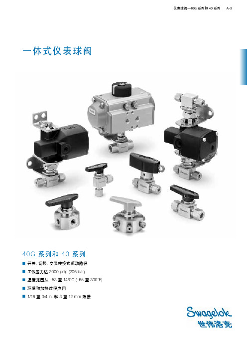
40G 系列和 40 系列■ 开关,切换,交叉转换式流动路径■ 工作压力达 3000 psig (206 bar)■ 温度范围从 –53 至 148°C (–65 至 300°F)■ 环境和加热过程应用■ 1/16 至 3/4 in . 和 3 至 12 mm端接一体式仪表球阀世伟洛克仪表球阀世伟洛克一体式仪表球阀多年来一直受到各个行业的广泛认可和采用。
原始的世伟洛克 40 系列和最新的 40G 系列阀门都可应用于多种执行机构、流动路径和手柄选购件,同时很容易进行在线填料调节。
有关世伟洛克仪表球阀的重要信息世伟洛克球阀设计用于全开或全 闭位置。
在一段时间内没有拧过的阀门可 能会有更高的初始执行扭矩。
在阀门的使用寿命期限内,可能 需要进行填料调节以防泄漏。
■ 使用说明书会随每个 40G 系列和 40系列阀附送。
■ 每个 40G 和 40 系列阀门都在1000 psig (69 bar) 的条件下进行氮气测试,如果低于1000 psig (69 bar),则在其额定压力下进行测试。
40系列阀门填料必须重新调整以便用在比测试压力高的场合。
有关标准产品测试,请参见第 P A-7页;有关选购件产品测试,请参见第P A-24页。
■ 安装之前暴露到动态温度条件下的仪表球阀可能会丢失其初始填料负载。
可能需要进行填料调整。
■ 41G 和 42G 系列阀门需要 8 mm 深井式套筒,43G 系列阀门需要 9 mm的深井式套筒,来调节填料螺栓。
■ 41 和 42 系列阀门需要 3/8 in. 开口扳手;44 系列阀门需要 1/2 in. 开口扳手;45 系列阀门需要 5/8 in. 开口扳手,来调节填料螺栓。
■ 43 系列阀门需要转换接头来调节填料螺栓。
订购号:MS-WK-4340G 系列和 40 系列比较➀活动负载 PFA (适用于所有尺寸)和UHMWPE ( 适用于41,42和43系列阀门的尺寸)填料可用于扩展至低温额定值 –53°C (–65°F)。
SMC水流量开关说明书
*线路 ・ 请勿重复的弯折及拉伸导线。
如果导线的配置可能导致重复用力弯折及拉伸,将引起断线。 另外,弯曲的半径原则上在 R65mm 以上。 ・ 请勿错误接线。 错误接线的不同情况,可能破坏流量开关。 ・ 请勿在接通电源时进行接线作业。 可能导致单元内部发生破损或错误运转。 ・ 请勿与动力线及高压线使用相同的接线线路。 因动力线・高压线输出的信号线中的噪音・电涌的混入可能导致发生错误的运转。 流量开关的接线线路请与动力线・高压线分开(不同线路)配置。 ・ 请确认线路的绝缘性。 如果绝缘不良(与其它线路混触,接线末端间的不良 etc),由于向流量开关附加过大电压负荷或混入电 流,可能会导致流量开关破坏。 ・ 为了防止混入噪音・电涌,请尽量缩短线路。 请将长度维持在 100m 以下。 *使用环境 ・ 请勿在腐蚀性气体及液体中使用。 可能导致故障、错误运转。 ・ 请勿在水・药液・油飞溅的场所使用。 可能导致故障、错误运转。 ・ 请勿在发生磁场的场所使用。 可能导致流量开关的错误运转。 ・ 请勿在经常会被水飞溅的环境下使用流量开关。 请避免在经常会被水飞溅的环境下使用流量开关。 绝缘不良、流量开关内部密封树脂的膨胀可能导致错误运转。 ・ 请勿在油分・药品环境中使用。 对于在切削液及清洗液等、各种油类及药品的环境下使用时,有时短期内也有可能对流量开关产生恶 性影响(绝缘不良、流量开关树脂的膨胀所导致的错误运装、导线硬化等)。 ・ 请勿在温度不稳定的环境下使用。 在正常气温变化以外的温度变化环境中使用,可能对流量开关内部造成恶性影响。 ・ 请勿在电涌发生源的场所内使用。 在流量开关周围,如发生大量电涌的装置设备(电磁式升降机·高频诱导炉·电动机等)放置时,可能导致 流量开关内部回路元件的老化或者破损。因此,请考虑电涌发生源的对策,同时注意避免管路的混触。 ・ 请勿使用发生电涌的负荷。 在继电器・电磁阀等直接驱动可发生电涌电压的负荷上,请使用内藏型电涌吸收元件的产品。 ・ 因在 CE 标注中未含对雷电涌的耐性,所以请在装置方面制定雷电涌对策。 ・ 请勿让线路杂物等异物混入产品内部。 可能导致故障、错误运转,所以请勿让线路杂物等异物混入流量开关内部。
斯沃琪洛克 AFS 球阀产品手册说明书

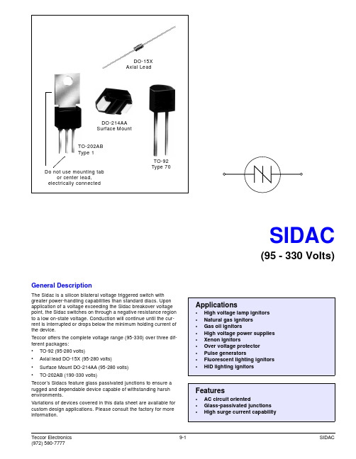
Swagelok® Alternative Fuel Ser vice (AFS) Ball ValvesFor High-Pressure, High-Flow ApplicationsSwagelok AFS Ball Valves■ Working pressures up to 6000 psig (413 bar)■ Flow coefficients (C v) from 4.0 to 13.8■ Fractional and metric Swagelok tube fittings; ISO and NPT pipe end connections available■ 316 stainless steel body and end connections■ Manual and pneumatic actuation2 Swagelok Alternative Fuel Service (AFS) Ball ValvesCertifications■ ANSI / AGA NGV 3.1 / CGA 12.3-M95,Classification: Manual valve Pressure: 4500 psig (310 bar)Temperature: –40 to 250°F (–40 to 121°C)■ ANSI / IAS NGV 4.6 / CSA 12.56-M99,Classification: Class APressure: 4500 psig (310 bar)Temperature: –40 to 185°F (–40 to 85°C)■ ECE R110 Manual Service Valve Type ApprovalClassification: Class 0Pressure: 3770 psig (260 bar)Temperature: –40 to 248°F (–40 to 120°C)■ Certifications do not include attachments to the valve,such as actuators or a different handle mechanism.Features■ High flow—C v from 4.0 to 13.8■ All wetted components arecompatible with hydrogen andcompressed natural gas (CNG)■ Maximum pressure rating: 6000 psig(413 bar)■ Temperature rating: –40 to 250°F(–40 to 121°C)■ Low operating torque■ No packing adjustment required ■ Field repairable with seal kitSwagelok Alternative Fuel Service (AFS) Ball ValvesImportant InformationAbout Swagelok AFS Ball ValvesSwagelok AFS ball valves are designed to be used inthe fully open or fully closed position.Valves that have not been cycled for a period of timemay have a higher initial actuation torque.Pressure-Temperature RatingsRatings are based on ASME Code for Pressure Piping B31.3, Process Piping. To determine working pressure ratings in accordance with ASME B31.1, Power Piping, for 316 stainless steel, multiply pressure by:■ 0.86 for temperatures from 100 to 200°F (37 to 93°C).■ 0.82 for temperatures up to 250°F (121°C).consistent, low actuation torquechemical compatibilitypressure systemsSwagelok Alternative Fuel Service (AFS) Ball Valves 3USAUSAEUROFlow Data at 70°F (20°C)NitrogenFlow,stdL/minNitrogenFlow,stdft3/minPressure Drop, psiPressure Drop, barInlet Pressure 3600 psig (248 bar)Inlet Pressure 5000 psig (344 bar)NitrogenFlow,stdL/minNitrogenFlow,stdft3/minPressure Drop, psiPressure Drop, barMaterials of ConstructionWetted components listed in italics.412510113131418678919121615174 Swagelok Alternative Fuel Service (AFS) Ball ValvesOrdering Information and DimensionsSelect an ordering number.Dimensions, in inches (millimeters), are for reference only and are subject to change.➀ V alves can be ordered with two different end connections. Contact your authorized Swagelok sales and service representative.➁ N ot available with AGA, IAS, and ECE R110 certifications; not recommended for panel mounting; not available with pneumatic actuator.➂ T hread type ISO/BSP (tapered), based on DIN 3852, Swagelok RT fittings.See specifications ISO 7/1, BS EN ISO 10226-1, and JIS B0203.Options and AccessoriesLocking Brackets■ Designed to lock valve in the openand closed position■ Accommodates shackle diametersup to 0.344 in. (8.7 mm)■ To order the locking bracket factory-assembled on a valve, add -LH to the valve ordering number.Example: SS-AFSS6-LHTo order the locking bracket for fieldassembly, use kit ordering number: SS-51K-AFS-LHHandle OptionsBlack nylon directional handles are standard.■ To order adirectional handle ofanother color,add a handleto the valve ordering number.Example: SS-AFSS6-RD■ To order a nylon ovalhandle, add -K to the valve ordering number.Example: SS-AFSS6-K ■ To order a black aluminumdirectional handle, add -AHD to the valve ordering number.Example: SS-AFSS6-AHDHandle KitsThe replacement handle kit includes a handle with set screw and instructions.■ Black nylon directional handle kitordering number: NY-5K-AFS-BKTo order a nylon directional handle kitin a color other than black, replace -BK in the kit ordering number with a handle color designator.Example: NY-5K-AFS -RD ■ Nylon oval handle kit orderingnumber: NY-5K-AFSK-BK■ Black aluminum directional handle kitordering number: A-5K-AFS-BKStem Seal Material OptionUltralow-temperature fluorocarbon FKM is standard. Ultralow-temperature nitrile (Buna C) is available as an option to enhance valve cycle life. Valves with ultralow-temperature nitrile have atemperature rating of –40 to 200°F (–40 to 93°C) and are not certified to AGA, IAS, or ECE R110.To order, add -BCS to the valve ordering number.Example. SS-AFSS6-BCSSwagelok Alternative Fuel Service (AFS) Ball Valves 5SwagelokPneumatic ActuatorsThe Swagelok rack and pinion pneumatic actuator is compact,lightweight, easily mountable, and can be operated with standard shop air. The actuators are available in spring-return and double-acting modes. For technical data, including materials of construction, air displacement, and weight, see the Swagelok Ball Valve Actuation Options catalog, MS-02-343.DimensionsDimensions, in inches (millimeters), are for reference only and are subject to change.Actuated assemblies mustbe properly aligned andsupported. Improper alignment or inadequate support of the actuated assembly may result in shorter valve life.Actuator Pressure at Maximum System PressureRequired pressures based on valve performance using pressurized air or nitrogen.For dual-mounted assemblies (two valves mounted to one actuator), add DM to the ordering number. Example: SS-AFSS6-33DHT DMActuator Service Ratings➀ M aximum working pressure for valves mounted to low-temperature service actuators is4500 psig (310 bar).Factory-Assembled ActuatorsTypical Ordering NumberD = Double actingC = Normally closed spring return O = Normally open spring returnD H TActuator Service N one = StandardHT = High temperature LT = Low temperature ➀➀ M aximum working pressurefor valves mounted to low-temperature service actuators is 4500 psig (310 bar).Ordering InformationActuators for Field AssemblyOrder one actuator kit and one mounting bracket kit for each valve.Mounting bracket kit ordering number:MS-MB-AFS-133➀ M aximum working pressure for valves mounted to low-temperature service actuators is 4500 psig (310 bar).6 Swagelok Alternative Fuel Service (AFS) Ball ValvesISO 5211-Compliant Pneumatic ActuatorsSwagelok ISO 5211-compliant rack and pinion pneumatic actuators are available in spring-return and double-acting modes.For technical data, including actuator materials of construction and weight, see the Swagelok Ball Valve Actuation Options catalog, MS-02-343.For additional information on selecting and sizing ISO 5211-compliantactuators, see the Actuated Ball Valve Selection Guide—ISO 5211-Compliant Actuator Mounting Bracket Kits, MS-02-136.Factory-Assembled ActuatorsTypical Ordering NumberD = Double actingC4 = Normally closed spring return O4 = Normally open spring returnD H TActuator Service N one = StandardHT = High temperatureActuated assemblies mustbe properly aligned andsupported. Improper alignment or inadequate support of the actuated assembly may result in shorter valve life.Ordering InformationActuators for Field AssemblyOrder one actuator kit and one mounting bracket kit for each valve.Mounting bracket kit ordering number:SS-MB-AFS-F05-14DIN-MActuator Service RatingsDimensionsDimensions, in inches (millimeters), are for reference only and are subject to change.Swagelok Alternative Fuel Service (AFS) Ball Valves 7Maintenance KitsKit components are of the same materials and grades listed in Materials of Construction, page 3.Seat Seal KitsThe seat seal kit contains two seats, seat O-rings, seatbackup rings, seat springs, end screw gaskets, lubricant with Material Safety Data Sheet (MSDS), and instructions.Kit ordering number: SS-9K-AFSStem and Seat Seal KitsThe stem and seat seal kit contains a stem O-ring, two guide rings, stem backup ring, thrust washer, packing bolt gasket, two seats, seat O-rings, seat backup rings, seat springs, end screw gaskets, lubricant with Material Safety Data Sheet (MSDS), and instructions.Kit ordering number: SS-91K-AFSTo order a kit with a stem O-ring of optional ultralow-temperature nitrile (Buna C) material, use kit ordering number: SS-91K-AFS-BCSOptions for ISO 5211-Compliant andSwagelok Pneumatic ActuatorsSwagelok offers a range of accessories to enhance instrumentation and process ball valve performance and control, including solenoid valves, limit switches, and position sensors. Factory assemblies and kits for field assembly are available.For more information, see the Swagelok Ball ValveActuation Options catalog, MS-02-343.Safe Product SelectionWhen selecting a product, the total system design must be considered to ensure safe, trouble-free performance. Function, material compatibility, adequate ratings,proper installation, operation, and maintenance are the responsibilities of the system designer and user.Warranty InformationSwagelok products are backed by The Swagelok Limited Lifetime Warranty. For a copy, visit or contact your authorized Swagelok representative.Swagelok—TM Swagelok Company © 2004–2014 Swagelok Company Printed in U.S.A., AGS November 2014, R11MS-02-303。
丹佛斯-AKS41-ICAD-EKC347电动阀使用说明书

丹佛斯-AKS41-ICAD-EKC347电动阀使用说明书丹佛斯 AKS41 ICAD EKC347电动阀使用说明书本系统采用Danfoss的一套组合(AKS41液位传感器+(ICM+ICAD封闭式电动阀)+EKC347控制器)进行供液控制。
EKC347控制器可以根据AKS41液位传感器提供的4~20mA液位信号来精确控制ICM封闭式电动阀的开度。
以下分别给出AKS41液位传感器、ICAD电动阀马达(电动阀)、EKC347控制器的中文操作指南,如果与英文操作指南有冲突,以英文为准。
一、AKS41液位传感器、ICAD电动阀马达、EKC347控制器的初始设定AKS41液位传感器、ICAD电动阀马达、EKC347控制器必须进行初始设定。
1.1、液位控制器EKC347的设定设定●上电几秒,待显示0.00后,才允许开始设定;●同时按住两按钮,进入液位设定状态,显示值会不断闪动,按上下键调定设定值,设定完后再同时按住两键进行确认;●接着上步操作,按住上面的按键不放几秒钟后,可找到其它设置项r06、r12等进行设置;●待所有参数均设定完毕后,放开所有按键,一段时间后,显示自动恢复到原始画面。
注意:显示r12等设定项后,同时按住两键进入参数设定状态,通过按上下两键调定具体设定值,参数值设定完毕后,务必再次同时按住两键进行确认。
LED显示:当前实际液位值,按一下“下按键”,则LED显示为电动阀开度。
具体设定值参见以下表格:1.2、电动阀ICAD马达初始设定●按住中间的○按键几秒钟后,按▲▼键找到i10项,按下○键进入密码输入状态,再通过▲▼键找到密码值(密码为11),然后再按一下○键进行确认;●输入密码后便可以对参数进行设定了,按▲▼键找到需要设定的项,然后按○键,进入参数设定状态,通过按▲▼键设定参数值,参数设定完后,再按一下○键进行确认;设定完后电动阀会进行自动调节,发出嗡嗡的震动,且显示100%,说明设定正确。
美的电水壶CEKS001说明书

3
Spout
Lid Lid opening button Water gauge Handle
Pilot lamp/ Switch button Power base
120V
4
5、Do not immerse nito water. The surface of the kettle may be wiped over with a damp cloth and polished with a soft dry cloth.
27、This appliance has a polarized plug (one blade is wider than the other). To reduce the risk of electric shock, this plug is intended to fit into a polarized outlet only one way. If the plug does not fit fully into the outlet, reverse the plug. If it still does not fit, contact a qualified electrician. Do not attempt to modify the plug in any way.″
Please read the instructions carefully before use the machine Please properly retention of the instructions for your future reference
When using electrical appliances, basic safety precautions should always be followed, including the following:
白蜂科技 B251 碳质钢球式阀门数据表说明书
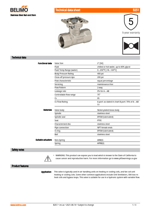
B251•ApplicationStainless Steel Ball and StemTechnical dataFunctional dataValve Size 2" [50]Fluidchilled or hot water, up to 60% glycol Fluid Temp Range (water)0...250°F [-18...120°C]Body Pressure Rating 400 psi Close-off pressure ∆ps 200 psiFlow characteristic equal percentage Servicing maintenance-free Flow Pattern 2-way Leakage rate0% for A – AB Controllable flow range 75°Cv65Cv Flow RatingA-port: as stated in chart B-port: 70% of A – AB CvMaterialsValve body Nickel-plated brass body Spindle stainless steel Spindle seal EPDM (lubricated)SeatPTFE Characterized disc stainless steel Pipe connection NPT female ends O-ring EPDM (lubricated)Ballstainless steel Suitable actuators Non-Spring ARB(X)SpringAFRB(X)Safety notesWARNING: This product can expose you to lead which is known to the State of California to cause cancer and reproductive harm. For more information go to Product featuresThis valve is typically used in air handling units on heating or cooling coils, and fan coil unit heating or cooling coils. Some other common applications include Unit Ventilators, VAV box re-heat coils and bypass loops. This valve is suitable for use in a hydronic system with variable flow.B251 Flow/Mounting detailsTwo-way valves should be installed with thedisc upstream.DimensionsDimensional drawingsARB, ARXA B C D E F H110.2" [260] 4.9" [125]7.7" [196] 6.0" [152] 1.7" [44] 1.7" [44] 1.2" [30]ARB N4, ARX N4, NRB N4, NRX N4A B C D E F11.4" [289] 4.9" [125]9.8" [249]7.6" [194] 3.1" [80] 3.1" [80]ARQB, ARQXA B C D E F H1H29.9" [251] 4.9" [125]7.5" [191] 6.1" [155] 2.3" [58] 2.3" [58]0.8" [20]0.6" [15]AFRB, AFRXA B C D E F11.3" [286] 4.9" [125]10.6" [268]8.9" [225] 2.0" [51] 2.0" [51]B251AFRB N4, AFRX N4A B C D E F13.0" [330] 4.9" [125]10.3" [262]9.3" [235] 3.4" [86] 3.4" [86]AFRB24-S On/Off, Spring Return, AC/DC 24 VTechnical dataElectrical data Nominal voltage AC/DC 24 VNominal voltage frequency50/60 HzPower consumption in operation 5 WPower consumption in rest position 2.5 WPower consumption for wire sizing7.5 VATransformer sizing7.5 VA (class 2 power source)Auxiliary switch 2 x SPDT, 3 A resistive (0.5 A inductive) @ AC250 V, one set at 10°, one adjustable 10...90°Switching capacity auxiliary switch 3 A resistive (0.5 A inductive) @ AC 250 VElectrical Connection(2) 18 GA appliance cables with 1/2" conduitconnectors, 3 ft [1 m],Overload Protection electronic throughout 0...95° rotationFunctional data Direction of motion motor selectable by ccw/cw mountingDirection of motion fail-safe reversible with cw/ccw mountingManual override 5 mm hex crank (3/16" Allen), suppliedAngle of rotation90°Running Time (Motor)75 sRunning time fail-safe<20 sNoise level, motor45 dB(A)Noise level, fail-safe62 dB(A)Position indication MechanicalSafety data Degree of protection IEC/EN IP54Degree of protection NEMA/UL NEMA 2Enclosure UL Enclosure Type 2Agency Listing cULus acc. to UL60730-1A/-2-14, CAN/CSAE60730-1:02, CE acc. to 2014/30/EU and2014/35/EU; Listed to UL 2043 - suitable for usein air plenums per Section 300.22(c) of the NECand Section 602.2 of the IMCQuality Standard ISO 9001Ambient temperature-22...122°F [-30...50°C]Storage temperature-40...176°F [-40...80°C]Ambient humidity Max. 95% RH, non-condensingServicing maintenance-freeElectrical installationINSTALLATION NOTESActuators with appliance cables are numbered.Provide overload protection and disconnect as required.AFRB24-STwo built-in auxiliary switches (2x SPDT), for end position indication, interlock control, fanstartup, etc.Actuators may be powered in parallel. Power consumption must be observed.Parallel wiring required for piggy-back applications.Apply only AC line voltage or only UL-Class 2 voltage to the terminals of auxiliary switches.Mixed or combined operation of line voltage/safety extra low voltage is not allowed.Meets cULus requirements without the need of an electrical ground connection.Warning! Live electrical components!During installation, testing, servicing and troubleshooting of this product, it may be necessaryto work with live electrical components. Have a qualified licensed electrician or other individualwho has been properly trained in handling live electrical components perform these tasks.Failure to follow all electrical safety precautions when exposed to live electrical componentscould result in death or serious injury.Wiring diagramsOn/Off Auxiliary SwitchesDimensions。
- 1、下载文档前请自行甄别文档内容的完整性,平台不提供额外的编辑、内容补充、找答案等附加服务。
- 2、"仅部分预览"的文档,不可在线预览部分如存在完整性等问题,可反馈申请退款(可完整预览的文档不适用该条件!)。
- 3、如文档侵犯您的权益,请联系客服反馈,我们会尽快为您处理(人工客服工作时间:9:00-18:30)。
Notes: 1.Wavelength: +/-1nm. 2. Forward Voltage: +/-0.1V.
Absolute Maximum Ratings at TA=25°C
Parameter Power dissipation DC Forward Current Peak Forward Current [1] Reverse Voltage Operating / Storage Temperature
Description
The Super Bright Orange device is made with AlGaInP (on GaAs substrate) light emitting diode chip.
Package Dimensions& Internal Circuit Diagram
Notes: 1. All dimensions are in millimeters (inches), Tolerance is ±0.25(0.01")unless otherwise noted. 2. The specifications, characteristics and technical data described in the datasheet are subject to change without prior notice. 3. The gap between the reflector and PCB shall not exceed 0.25mm.
Reel Dimension
Tape Specifications (Units : mm)
SPEC NO: DSAG0273 APPROVED: WYNEC
REV NO: V.6 CHECKED: Joe Lee
DATE: MAR/21/2011 DRAWN: J.Yu
PAGE: 4 OF 5 ERP: 1351000405
Note: 1. 1/10 Duty Cycle, 0.1ms Pulse Width.
Super Bright Orange 75 30 195 5 -40°C To +85°C
Units mW mA mA V
SPEC NO: DSAG0273 APPROVED: WYNEC
REV NO: V.6 CHECKED: Joe Lee
芯天下--/
PACKING & LABEL SPECIFICATIONS
ACSC02-41SEKWA-F01
SPEC NO: DSAG0273 APPROVED: WYNEC
REV NO: V.6 CHECKED: Joe Lee
DATE: MAR/21/2011 DRAWN: J.Yu
Part No. Dice Lens Type Iv (ucd) [1] @ 10mA Min. ACSC02-41SEKWA-F01 Super Bright Orange (AlGaInP) White Diffused 21000 Typ. 37000 Common Cathode, Rt. Hand Decimal. Description
DATE: MAR/21/2011 DRAWN: J.Yu
PAGE: 2 OF 5 ERP: 1351000405
芯天下--/
Super Bright Orange
ACSC02-41SEKWA-F01
SPEC NO: DSAG0273 APPROVED: WYNEC
Note: 1. Luminous intensity/ luminous Flux: +/-15%.
Electrical / Optical Characteristics at TA=25°C
Symbol λpeak λD [1] Δλ1/2 C VF [2] IR Parameter Peak Wavelength Dominant Wavelength Spectral Line Half-width Capacitance Forward Voltage Reverse Current Device Super Bright Orange Super Bright Orange Super Bright Orange Super Bright Orange Super Bright Orange Super Bright Orange Typ. 610 601 29 15 2.1 2.5 10 Max. Units nm nm nm pF V uA Test Conditions IF=20mA IF=20mA IF=20mA VF=0V;f=1MHz IF=20mA VR=5V
PAGE: 5 OF 5 ERP: 1351000405
芯天下--/
REV NO: V.6 CHECKED: Joe Lee
DATE: MAR/21/2011 DRAWN: J.Yu
PAGE: 3 OF 5 ERP: 13510004-41SEKWA-F01
Recommended Soldering Pattern (Units : mm; Tolerance: ± 0.15)
SURFACE MOUNT DISPLAY
Part Number: ACSC02-41SEKWA-F01 Super Bright Orange
Features
0.2inch digit height. Low current operation. Excellent character appearance. Mechanically rugged. Gray face,white segment. Package : 650pcs / reel. Moisture sensitivity level : level 2a. RoHS compliant.
SPEC NO: DSAG0273 APPROVED: WYNEC
REV NO: V.6 CHECKED: Joe Lee
DATE: MAR/21/2011 DRAWN: J.Yu
PAGE: 1 OF 5 ERP: 1351000405
芯天下--/
Selection Guide
