VI-JTXEX中文资料
Vijeo Citect 7.30 快速入门教程 2 高级配置
!Vijeo Citect快速入门教程 2高级配置本教程将带领您创建并运行一个Vijeo Citect V7.30的工程。
目录1介绍 (3)1.1课程目的 (3)2安全验证 (4)3设备导入 (6)4超级精灵 (13)4.1创建超级精灵 (13)5精灵 (24)5.1创建精灵 (24)5.2在图形页面上使用精灵 (29)6标签数据质量 (33)6.1标签覆盖 (33)6.2控制禁止 (39)1介绍欢迎您购买并使用Vijeo Citect系列产品。
该教程是Vijeo Citect快速入门教程1的扩展教程,以教程1中的概念及项目配置为基础。
如果您还未完成快速入门教程1的内容,请从现在开始,并在开始本教程的学习前,完成教程1的内容。
1.1课程目的该教程将介绍Vijeo Citect产品的高级配置:∙安全设置——电子签名及多用户验证∙超级精灵——简化项目配置及维护∙精灵——简化项目配置及维护∙标签数据质量及标签管理∙项目对象块创建中的设备导入过程1.1.1商标注册Vijeo Citect, Vijeo Citect Lite, Vijeo Historian, Vijeo Designer, Vijeo Look, AMPLA都是施耐德电气的注册产品。
Windows 是微软公司的注册产品。
其他品牌和产品名称均为其品牌所有权公司的注册产品。
2安全验证Vijeo Citect中的安全验证大大简化了数字签名与多用户验证功能。
本练习将为泵1设置签名验证,要求用户在切换到手动模式之前输入签名。
(设置Pump_1_Mode值为1)。
在图形编辑器中打开“我的页面”,双击“手动”按钮,在“输入”标签中修改指令为:MultiSignatureTagWrite(“Pump_1_Mode”, ”1”, ””, ”kernel”, “”, “”, “”)保存页面。
在工程编辑器中编译项目并运行。
项目运行时,打开“我的页面”,点击“手动”按钮。
viliv X70 EX移动互联网设备使用说明书

User’s ManualThanks for purchasing viliv.Please read the precautions throughly before using the product.ContentsSafety Precautions for Use ‥‥‥‥‥‥‥‥‥‥‥‥‥4 Names of Parts ‥‥‥‥‥‥‥‥‥‥‥‥‥‥‥‥‥‥7 Basic Components ‥‥‥‥‥‥‥‥‥‥‥‥‥‥‥‥‥‥‥‥‥7 T op/Front Side ‥‥‥‥‥‥‥‥‥‥‥‥‥‥‥‥‥‥‥‥‥8 Left/Right View ‥‥‥‥‥‥‥‥‥‥‥‥‥‥‥‥‥‥‥‥‥9 Rear View ‥‥‥‥‥‥‥‥‥‥‥‥‥‥‥‥‥‥‥‥‥‥‥10Installation and Cable Connection ‥‥‥‥‥‥‥‥‥‥11 Power Connection (Charging Adaptor) ‥‥‥‥‥‥‥‥‥‥‥11 USB Data Link Connection ‥‥‥‥‥‥‥‥‥‥‥‥‥‥‥‥12 USB Connection ‥‥‥‥‥‥‥‥‥‥‥‥‥‥‥‥‥‥‥‥‥12 Separating·Attaching Battery ‥‥‥‥‥‥‥‥‥‥‥13 Separating Battery ‥‥‥‥‥‥‥‥‥‥‥‥‥‥‥‥‥‥‥‥13 Attaching Battery ‥‥‥‥‥‥‥‥‥‥‥‥‥‥‥‥‥‥‥‥13 Inserting·Extracting USIM Card ‥‥‥‥‥‥‥‥‥‥‥‥‥‥14Basic Operation ‥‥‥‥‥‥‥‥‥‥‥‥‥‥‥‥‥‥15 Turning the Power On/Off ‥‥‥‥‥‥‥‥‥‥‥‥‥‥‥‥‥15 Setting/Cancelling Hold Function ‥‥‥‥‥‥‥‥‥‥‥‥‥‥15 Jog and Function Buttons ‥‥‥‥‥‥‥‥‥‥‥‥‥‥‥‥‥16 Running Virtual Keyboard ‥‥‥‥‥‥‥‥‥‥‥‥‥‥‥‥17 Set Up for villv Manager ‥‥‥‥‥‥‥‥‥‥‥‥‥‥‥‥‥17 Using for the First Time ‥‥‥‥‥‥‥‥‥‥‥‥‥‥18 Using for the First Time ‥‥‥‥‥‥‥‥‥‥‥‥‥‥‥‥‥‥18Recovery Solution (AMI Rescue) Guide ‥‥‥‥‥‥‥‥20 Way to Use Recovery Solution (AMI Rescue)‥‥‥‥‥‥‥‥‥20 Specifications ‥‥‥‥‥‥‥‥‥‥‥‥‥‥‥‥‥‥‥21 General Specifications ‥‥‥‥‥‥‥‥‥‥‥‥‥‥‥‥‥‥21This equipment has been tested and found to comply with the limits for a Class B digital device, pursuant to part 15 of the FCC Rules. These limits are designed to provide reasonable protection against harmful interference in a residential installation. This equipment generates, uses and can radiate radio frequency energy and, if not installed and used in accordance with the instructions, may cause harmful interference to radio communications. However, there is no guarantee that interference will not occur in a particular installation. If this equipment does cause harmful interference to radio or television reception, which can be determined by turning the equipment off and on, the user is encouraged to try to correct the interference by one or more of the following measures:- Reorient or relocate the receiving antenna.- Increase the separation between the equipment and receiver.- Connect the equipment into an outlet on a circuit different from that to which the receiver is connected.- Consult the dealer or an experienced radio/ tv technician for help.Information to UserIn August 1996 the Federal Communications Commission(FCC) of the United States with its action in Report and order 96-326 adopted an updated safety standard for human exposure the ra-dio frequency electromagnetic energy emitted by FCC regulated transmitters. Those guidelines are consistent with the safety standard previously set by both U.S. and international standards bodies. The design of ‘X70 EX’ complies with the FCC guidelines and those international standards. Use only the supplied or an approved antenna. Unauthorized antennas, modifications, or attachments could impair call quality, damage your ‘X70 EX’, or result in violation of FCC regulations.‘X70 EX’ was tested for typical body-wom operation using the optional belt-clip / holster placed touch(0cm) from the body. The use of non-tested accessories or other body-wom operations may not comply with FCC exposure requirements and should be avoided.FCC RF Exposure InformationRear ViewThe figure below shows the rear side of the main body without the battery. (Refer to Page 13 for Separating/Attaching battery.)USB Data Link ConnectionA USB cable is connected to the USB Data Link port on the right side of the station.Inserting · Extracting USIM CardHow to Insert : L et the front of a USIM card face the USIM card slot and then push it in the arrow direction until a click sound is heard. (If, however, you push the USIMcard using too much force, the card may be damaged.)How to Extract : S ince this device adopts a one-touch method, you may gently press on the end of the USIM card to extract it automatically. (Pull out the USIM cardslightly protruded.)Turning the Power On/OffSetting/Cancelling Hold FunctionJog and Function ButtonsThe Jog key has different functions in accordance with the program functions.Running Virtual KeyboardSet Up for villv Managerviliv Manager is executed by double touching vilivManager on the screen.1Wireless LAN Power Turn on/off self-powered wireless LAN function.2Camera Power Turn on/off self-powered Camera function.3Modem Power Turn on/off self-powered Modem function.4Windows Booting Option 1. OFF: Always start with OFF status.2. Last Status: Start with the last status.3. ON: Always start with ON status.5Brightness of LCD Adjust by status bar or -, + button.6Setting Vibration 1. No Use: Do not use vibration function.2. When using soft keyboard: O perate only if soft keyboard is used.3. Always Use: O perates when operating for all touches.7Set Up for Windows Start Program 1. Set whether or not to execute Cube UI automatically.2. S et whether or not to execute viliv Managerautomatically.1423567Using for the First TimeFor each Windows installation process, the installation time may vary depending on the process. Please wait until the installation is complete.It may take a couple of minutes. Please wait for a moment.Way to Use Recovery Solution (AMI Rescue)General Specifications。
Vijeo Designer Basic 软件教程 - 中文
22
启 动 Vijeo Designer . . . . . . . . . . . . . . . . . . . .
26
基本设置 . . . . . . . . . . . . . . . . . . . . . . . . . .
27
创建变量 . . . . . . . . . . . . . . . . . . . . . . . . . .
29
创建画面 . . . . . . . . . . . . . . . . . . . . . . . . . .
33
数字和文本显示 . . . . . . . . . . . . . . . . . . . . . . .
36
图形对象 . . . . . . . . . . . . . . . . . . . . . . . . . .
2 GB 硬 盘 空 间 或 更 多
Microsoft Windows XP Professional(Service Pack 3 或 更 高 版 本) Microsoft Windows 7 32 和 64 位 Microsoft Windows 8.1 32 和 64 位
Microsoft Internet Explorer 6.0 ( 推 荐 版 本 7 或 者 更 高 )
61
验证,生成和纠正错误 . . . . . . . . . . . . . . . . . . . .
62
下载工程 . . . . . . . . . . . . . . . . . . . . . . . . . .
64
索引 . . . . . . . . . . . . . . . . . . . . . .
施耐德电气Vijeo-Citect-培训-入门
– 何时采样由触发事件决定
周期事件
– 仅当触发值为真时趋势按照预定的周期采样
Exercise 1练习 9.1
趋势标签
趋势模板风格 (pg9-4)
Exercise 1练习 9.2
显示趋势
趋势
本章小节
趋势标签 显示趋势
Process Analyst过程分析
Chapter 10
过程分析
趋势标签 显示趋势
显示趋势 (pg 9-1)
是示不需要激活 需要建立趋势标签
趋势标签 (pg9-2)
Variable Tag
Trend Tag
Trend Tag Files
从变量标签建立趋势标签 创建趋势页
Trend Page
Vijeo Citect 环境
分为两个不同部分:
– Runtime System运行系统 – 配置环境
• Citect 浏览器 • 项目编辑器 • Citect 图形编辑器 • Cicode编辑器 • Vijeo Citect 帮助
系统要求
检查你的硬件要求
最小硬件要求 过程分析 – 高图形负荷
– One or Two Tags (ANDed)1个 或两个标签(和的关系)
Hardware硬件
– Pre-configured in CitectHMI/SCADA system在 Vijeo Citect中已经预先配置好了
Advanced高级
– Action on Cicode program 由 Cicode 程序触发报警
本章一览
什么是过程分析? 过程分析ActiveX Control 过程分析属性 在过程分析中显示数据 显示趋势 显示报警
过程分析 (pg10-2)
Vijeo Citect v7.1安装指南

The present documentation is intended for qualified technical personnel responsible for the implementation, operation and maintenance of the products described. It contains information necessary for the proper use of the products. However, those who wish to make a more "advanced" use of our products may find it necessary to consult our nearest distributor in order to obtain additional information.
版权
Copyright 2008 Schneider Electric Pty Ltd. 保留所有权利。
商标
Schneider Electric Pty Ltd. 已经尽最大努力提供了在本手册中提及的有关公司名称、产品和服务的商标信 息。
? Citect、CitectHMI 和 CitectSCADA 是 Citect Pty. Ltd. 的注册商标。
新功能...........................................................................................5 在 v7.0 中引入......................................................................6 在 v7.10 中引入:.................................................................8 版本 7.0 中的 Cicode 函数 ...................................................10
Turck磁感应传感器产品说明书

T 08:30:42+02:00型号BIM-UNT-AY1X/S1139货号4685763通过速度ð 10 m/s 重复性ï ± 0.1 mm 温度漂移ð 0.1 mm 磁滞ð 1 mm环境温度-25…+70 °C 输出性能2线, NAMUR 开关频率 1 kHz电压Nom. 8.2 VDC 无激励电流损耗ð 1.2 mA 激励电流损耗ï 2.1 mA认证依据KEMA 04 ATEX 1152 X 内置 电感(L ) / 电容 (C )180 nF / 350 µH防爆标志防爆标识为II 1 G/Ex ia IIC T6/II 1 D Ex ia D 20 T95°C(最大 U = 20 V, I = 60 mA, P = 80 mW)设计方型, UNT 尺寸28 x 5 x 6 mm 外壳材料塑料, PP 感应面材料塑料, PP 紧固螺母的固定扭矩0.4 Nm 连接电缆线缆材质3 mm, 蓝, Lif9YYW, PVC, 2 m线缆横截面2 x 0.14mm 防震动性55 Hz (1 mm)防冲击性30 g (11 ms)防护等级IP67MTTF2283 years 符合SN 29500 (Ed.99) 40 °C认证安装在以下剖面.Cylindrical design E N K F 开关状态指示LED指示灯 黄可供货电缆夹sATEX 防爆认证 II组设备,设备等级1G,可用为气体危险0区sATEX 防爆认证II组设备,设备等级1D,适用于粉尘危险2区s 适于T型槽气缸,无需安装附件s 可选择附件安装于其他外型气缸上s 单手可安装s 微调装置和固定器可直接安装在传感器上s 稳固的安装s 磁阻式传感器s 2线直流, nom. 8.2 VDCs输出遵循本安型DIN EN 60947-5-6(NAMUR)标准s输出方波信号s 常开s电缆连接接线图功能原理磁感应传感器感应磁场。
VI-FKE6-CMX中文资料
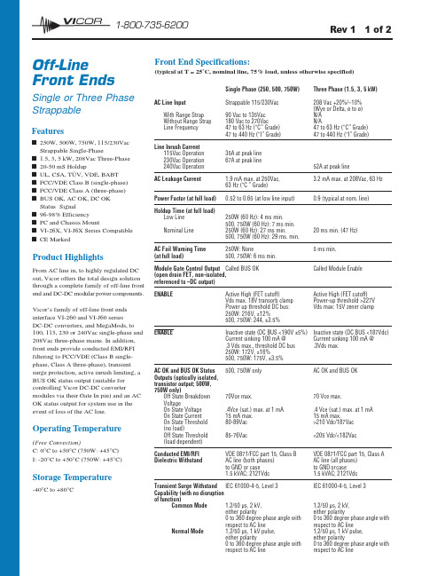
12 1-800-735-6200Features■250W, 500W, 750W, 115/230Vac Strappable Single-Phase■ 1.5, 3, 5 kW, 208Vac Three-Phase ■20-50 mS Holdup■UL, CSA, TÜV, VDE, BABT ■FCC/VDE Class B (single-phase)■FCC/VDE Class A (three-phase)■BUS OK, AC OK, DC OK Status Signal■96-98% Efficiency ■PC and Chassis Mount■VI-26X, VI-J6X Series Compatible ■CE MarkedProduct HighlightsFrom AC line in, to highly regulated DC out, Vicor offers the total design solution through a complete family of off-line front end and DC-DC modular power components.Vicor’s family of off-line front ends interface VI-260 and VI-J60 series DC-DC converters, and MegaMods, to 100, 115, 230 or 240Vac single-phase and 208Vac three-phase mains. In addition,front ends provide conducted EMI/RFI filtering to FCC/VDE (Class B single-phase, Class A three-phase), transient surge protection, active inrush limiting, a BUS OK status output (suitable for controlling Vicor DC-DC convertermodules via their Gate In pin) and an AC OK status output for system use in the event of loss of the AC line.Operating Temperature(Free Convection)C: 0°C to +50°C (750W: +45°C)I: -20°C to +50°C (750W: +45°C)Storage Temperature-40°C to +80°COff-Line Front EndsSingle or Three Phase StrappableFront End Specifications:(typical at T = 25˚C, nominal line, 75% load, unless otherwise specified)Rev 1 1 of 2107Rev 1 2 of 2For the latest Vicor Product Information: 12 1-800-735-6200INPUTOUTPUTFUSES 2,3,4...n: 3A/250V BUSSMAN PC-TRON750W — FUSE 1: 15A/250V BUSSMAN ABC-15,LITTLEFUSE 314-015FUSES 2,3,4...n: 3A/250V BUSSMAN PC-TRONFront End Selection ChartFront End Connection DiagramMounting Output Power (Watts)Model PC Chassis 250500750Single Phase VI-FPE6-CUX ■■VI-FKE6-CUX ■■VI-FPE6-CQX ■■VI-FKE6-CQX ■■VI-FPE6-CMX ■■VI-FKE6-CMX ■■Three Phase1,5003,0005,000VI-TKY6-CHX ■■VI-TKY6-CEX ■■VI-TRY6-CCX■■Notes:1.If input power is applied with the DC output BUS shorted, the active inrush circuitry will usually prevent Fuse 1 from blowing. Remove power, clear shorts, wait a few minutes and reapply input power.2.If unit is strapped for 115V operation and 230V is applied, the internal overvoltage crowbar will clear Fuse 1. Replace fuse, strap correctly and reapply power.3.To control EMI/RFI most effectively, the return path to earth ground from either the front end ormodules should be made via a good RF ground. User must assure proper grounding for safe operation.500400300200100Airflow (LFM)6004080706050500400300200100Airflow (LFM)A m b i e n t T e m p e r a t u r e °C6004080706050600500400300200100Airflow (LFM)A m b i e n t T e m p e r a t u r e °C500W750W。
VI-JNDEX中文资料
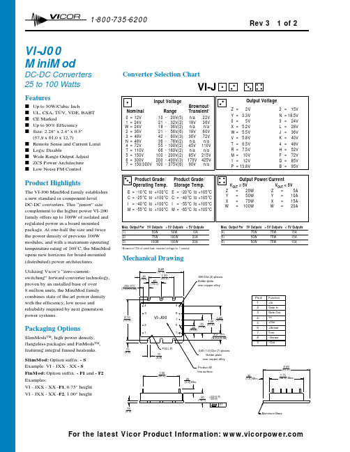
12 1-800-735-6200VI-J00MiniModDC-DC Converters 25 to 100 WattsProduct HighlightsThe VI-J00 MiniMod family establishes a new standard in component-level DC-DC converters. This “junior” size complement to the higher power VI-200family offers up to 100W of isolated and regulated power in a board mounted package. At one-half the size and twice the power density of previous 100W modules, and with a maximum operating temperature rating of 100˚C, the MiniMod opens new horizons for board-mounted (distributed) power architectures. Utilizing Vicor’s “zero-current-switching” forward converter technology,proven by an installed base of over 8 million units, the MiniMod family combines state of the art power density with the efficiency, low noise and reliability required by next generation power systems.Packaging OptionsSlimMods™, high power density,flangeless packages and FinMods™,featuring integral finned heatsinks.SlimMod: Option suffix: - S Example: VI - JXX - XX - SFinMod: Option suffix: - F1and - F2Examples:VI - JXX - XX -F1, 0.75" height VI - JXX - XX -F2, 1.00" heightConverter Selection ChartVI-JMax. Output For 5V Outputs > 5V Outputs < 5V Outputs(1)50W 50W 10A (2)75W 100W 20A (3)100W 100W 20AMax. Output For 5V Outputs > 5V Outputs < 5V Outputs(4)75W 75W 15A (5)50W 75W 15A (6)50W 75W 10AFeaturess Up to 50W/Cubic Inchs UL, CSA, TÜV, VDE, BABT s CE Markeds Up to 90% Efficiency s Size: 2.28" x 2.4" x 0.5"(57,9 x 61,0 x 12,7)s Remote Sense and Current Limit s Logic Disables Wide Range Output Adjust s ZCS Power Architecture sLow Noise FM ControlMechanical Drawing(7,6) Min.(3,0).12.30*Brownout 75% of rated load; transient voltage for 1 second.Rev 3 1 of 2For the latest Vicor Product Information: 12 1-800-735-620073Converter Specifications(typical at T BP =25°C, nominal line and 75% load, unless otherwise specified)VI-J00 E-GradeVI-J00 C-, I-, M-GradePARAMETERMIN.TYP.MAX.MIN.TYP.MAX.UNITSTEST CONDITIONSs Input Characteristics Inrush charge60x10-660x10-6100x10-6CoulombsNominal lineInput reflected ripple current – pp 10%10%I INNominal line, full load Input ripple rejectiondB 120 Hz, nominal line dB2400 Hz, nominal lineNo load power dissipation 1.3521.352Wattss Output Characteristics Setpoint accuracy 1.0%2.0%0.5% 1.0%V NOM Load/line regulation 0.5%0.05%0.2%V NOM LL to HL, 10% to Full Load Load/line regulation1.0%0.2%0.5%V NOM LL to HL, No Load to 10%Output temperature drift 0.020.010.02%/°C Over rated temperatureLong term drift 0.020.02%/1K hoursOutput ripple - pp: 2V, 3.3V 200100150mV20 MHz bandwidth 5V 5%2%3%20 MHz bandwidth 10-48V 3%0.75%1.5%20 MHz bandwidth Trim range 150%110%50%110%V NOM Total remote sense compensation 0.50.5Volts 0.25V max. neg. leg Current limit105%135%105%125%I NOM Automatic restartShort circuit current 105%140%105%130%I NOMs Control Pin Characteristics Gate out impedance 5050Ohms Gate in impedance 103103Ohms Gate in high threshold 66Volts Use open collectorGate in low threshold 0.650.65Volts Gate in low current 66mAs Dielectric Withstand Characteristics Input to output 3,0003,000V RMS Baseplate earthedOutput to baseplate 500500V RMS Input to baseplate 1,5001,500V RMSs Thermal Characteristics Efficiency78-88%80-90%Baseplate to sink 0.40.4°C/Watt With Vicor P/N 04308s Mechanical Specifications Weight3.0 (85) 3.0 (85)Ounces (Grams)110V, 12V and 15V outputs, standard trim range ±10%. Consult factory for wider trim range.For product compliance with agency standards please refer to pages 67 - 69.25+20Log( Vin Vout30+20Log ( VinVout20+20Log ( Vin)Rev 3 2 of 2For the latest Vicor Product Information: 。
Vijeo 标准培训

建立通讯
章节 4
Click to edit Master title style 建立通讯
本章一览
通讯向导 通讯对话框 变量标签 表单 测试通讯 结构化变量标签名 利用 Excel 来增加标签变量
Click to edit I/O (pg4-2) Vijeo Citect Master title style
Click -to edit Master title style 日程 Day 1 (pg1-4)
SCADA简介 客户机配置 管理项目 建立通讯 图形
Click -to edit Master title style 日程 Day 2 (pg1-4)
命令和控制
精灵 弹出页面和超级精灵 OFS Server 设备 事件 报警
Page 3-10
Click to edit Master title style 包含项目 (pg3-13)
检查新的选择
Hands-on Exercise
练习 3.4 包含项目
Page 3-14
Click to edit Master title style 管理项目
本章小结
新建项目 计算机配置向导 备份和恢复项目 包含项目
运行系统包括
运行程序 Vijeo Citect 内核 Cicode 诊断器
运行环境下 Vijeo Citect 通讯对象
I/O 设备 过程报警 符号
Click to edit Master title style Citect 浏览器 (pg 2-4)
自动启动和关闭项目编辑 器和图形编辑器 工程选择和管理 备份和恢复 启动其他应用程序
管理项目
章节 3
Click to edit Master title style 管理项目
Vijeo_Citect技术概要

随着时间的改变,用户对 SCADA 系统的要求也在不断改变。因此 用户怎样选择最好的架构呢?Vijeo Citect 为您提供了既灵活又 易于扩展的系统。
可扩展性
可扩展性是指在保持现有系统硬件和软件不变的 前提下,可任意改变系统规模的能力-无论是扩 大还是缩小。Vijeo Citect 极具创新性的可扩展架 构允许您的系统架构随着需求的增长而变化,同 时保留最初的投资。如果您需要添加一个控制终 端,只需在局域网中添加一台新的计算机,然后 将其指定为控制客户端即可。新的控制客户端可 共享相同的组态并通过第一台 Vijeo Citect 服务器 接收 I/O 的信息。
下图:网络故障容错
ඇਆਜ਼ࢽ܋ ဣཥ A+B+C
3
系统架构:可扩展性
OEM 解决方案
Vijeo Citect Lite 的设 计可满足单机系统的 应用。
Vijeo Citect Lite 是一 种可扩展的解决方案。 简单地修改软件授权 即可将其升级到 Vijeo Citect。
功能包括:
b 历史和实时趋 势、高级报警 以及报表制作 b 自定义的安装 b 支持在线的 多语言切换 b 两种脚本编程语 言-Cicode 和 CitectVBA b 统计过程控制 b 图形元素包括 精灵、超级精灵 和 ActiveX 控件
ඇਆਜ਼ࢽ܋ ဣཥ A+B
ဣཥ A
णඖޜခഗ (ዷ)
ဣཥ A
णඖޜခഗ (Ԣᆩ)
ဣཥ B
णඖޜခഗ (ዷ)
ဣཥ B
णඖޜခഗ (Ԣᆩ)
5
系统架构:灵活性
和经营业务一样,您的 SCADA 系统也必须对不断变化的需 求作出及时的调整。增加新的生产线或者来自成本节约的压 力都可能会让您觉得很棘手。Vijeo Citect 采用真正的客户 端/服务器架构,使您可以根据需求灵活修改您的系统。
Vijeo Citect 7.40 快速入门

Vijeo Citect 快速入门教程1Vijeo Citect的基础介绍本教程将带领您创建并运行一个Vijeo Citect V7.40的工程。
目录1介绍 (4)1.1课程目的 (4)1.2产品组件 (5)1.3术语 (6)2创建新工程 (7)2.1打开工程管理器 (7)2.2创建新工程 (8)3工程初始化 (9)3.1配置设备 (9)4创建页面 (21)4.1绘制图形对象 (24)4.2设置导航菜单 (38)4.3运行前准备 (41)4.4运行项目 (45)5高级图形对象 (47)5.1模拟量填充 (47)5.2滑块控制模拟量 (49)5.3文本 (51)5.4使用数字与键盘输入 (53)5.5使用动画符号与管道 (55)5.6颜色 (61)5.7使用符号库 (64)6警报、趋势及安全 (68)6.1使用警报 (68)6.2趋势 (72)6.3安全 (75)6.4查找与替换工具 (77)7运行 (80)7.1显示警报 (81)7.2浏览趋势 (84)8管理项目 (89)8.1备份项目 (89)8.2恢复项目 (90)8.3问题解决 (92)1 介绍该教程将帮助您快速入门Vijeo Citect系列产品。
在使用该教程之前请确认您已经在计算机上正确的安装了Vijeo Citect产品。
此外,进行该教程的学习并不需要Vijeo Citect授权。
1.1课程目的该教程将介绍Vijeo Citect产品的基础内容:•创建新工程•建立Vijeo Citect与PLC之间的通信•添加并配置设备✧设备类型✧标签✧警报✧趋势•创建图形页面✧使用页面模板✧绘制和修改图元✧使用按钮✧动态符号✧显示模拟量✧绘制管线✧将图元分组✧配置报警页面✧配置趋势页面•显示操作运行时间•使用安全策略•使用管理工具✧在运行过程中创建菜单✧打开标签调试表格•备份和恢复工程1.1.1商标注册本手册已经尽最大努力提供了在本手册中提及的有关公司名称、产品和服务的商标信息。
施耐德 Vijeo Designer V4.3 软件简介

人机界面市场部 钟仁
1
Vijeo Designer V4.3 软件
1
介绍摘要
2
Vijeo-designer结构
3
Mijeo-Designer4.3界面
4
Vijeo-Designer4.3功能
5
Vijeo-Designer4.4新功能
HMI - ZhongRen – 8th Dec. - chinese
OS abstraction layer (C++) Windows 2000/XP pSOS VxWorks
是大多数HMI应用要求的一体化解决方案 – 图形, 报警, 数据存储, 趋势, …. 开放性的Java允许客户自定义到一新高度 所有项目阶段都予以考虑 – 程序管理器 – 画面设计 (包括脚本) – 画面& PLC 模拟
HMI - ZhongRen – 8th Dec. - chinese
10
Module 3
Vijeo Designer 界面
HMI - ZhongRen – 8th Dec. - chinese
11
用户界面
工具栏 导航器 图形编辑器
属性栏 反馈区 图形列表 工具箱 状态栏
HMI - ZhongRen – 8th Dec. - chinese
HMI - ZhongRen – 8th Dec. - chinese
8
Vijeo-Designer 结构
类似 Microsoft Studio的设计环境
Vijeo-Designer HMI 程序 Vijeo-Designer runtime (JAVA & C++)
Vijeo Citect SCADA软件编程使用说明书
Schneider Vijeo Citect V7.1 SP2 SCADA软件编程使用说明书文件编号:__________________版本号:__________________发放编号:__________________持册人:__________________长沙华能自控集团目录一、VIJEO CITECT V7.1简介 (1)二、VIJEO CITECT V7.1安装 (1)三、VIJEO CITECT V7.1使用 (6)(一)、启动V IJEO C ITECT 7.1程序 (6)(二)、新建工程 (7)(三)、集群定义 (8)(四)、网络地址配置 (8)(五)、I/O服务器定义 (10)(六)、通信设置 (11)1.板卡设置 (11)2.端口设置 (12)3.定义I/O设备 (12)(七)、建立标签 (13)1.变量标签 (13)2.局部变量 (15)3.趋势标签 (17)(八)、图形编辑器 (19)1.编辑页面 (19)2.标签定义 (20)⏹遥测标签定义 (20)⏹遥控标签定义 (21)⏹遥信标签定义 (21)3.精灵和超级精灵 (22)⏹创建一个新的精灵 (22)⏹使用精灵(在图形页面上粘贴一个精灵) (24)(九)C ICODE脚本编辑器 (25)1.编辑Cicode脚本 (26)2.调用Cicode脚本 (27)⏹按钮调用 (27)⏹报表调用 (27)⏹事件调用 (29)(十)编译工程 (30)(十一)配置文件 (30)(十二)计算机设置向导 (31)(十三)运行工程 (32)四、SQL SERVER2008 (32)(一)安装 (32)(二)配置SQLS ERVER2008 (35)(三)恢复SQLS ERVER2008数据库 (37)(四)SQLS ERVER2008数据库备份 (45)五、VIJEO CITECT ODBC数据源设置 (46)六、VIJEO CICECT 7.1维护 (48)(一)工程备份 (48)(二)工程还原 (50)(三)备份C ITECT.INI文件 (51)一、Vijeo Citect V7.1简介Vijeo Citect是施耐德电气的一款专为Modicon控制平台量身打造的SCADA监控软件,是一个完全集成的HMI/SCADA解决方案,通过为客户提供高度可靠,扩展性极强的监控系统,从而实现低投入高回报的应用目的。
最新VT技术资料中文版
V T技术资料中文版乙烯基甲苯(对位、间位组成的)甲基苯乙烯涂料及树脂应用DELTECH 公司11911 SCENIC HIGHWAYBATON ROUGE, LA 70807电话: 225 358-0150传真: 225 358-3149仅供学习与交流,如有侵权请联系网站删除谢谢16目录销售规格:性质应用醇酸树脂模塑树脂辐射固化涂料乙烯基酯树脂其他应用仅供学习与交流,如有侵权请联系网站删除谢谢16VT出售规格属性指标单位方式纯度99.2 Min Wt % 乙烯基GC-01间-甲基苯乙烯56.0 典型Wt %对-甲基苯乙烯44.0 Wt %多聚体含量15 最大ppm ASTM D-2121 色度20 最大APHA ASTM D-1209 TBC抑制剂30-60 ppm ASTM D-4500PMS 出售规格属性指标单位方法纯度99.7 Min Wt % 乙烯基GC-01对-甲基苯乙烯99.0 典型Wt %聚合物含量15 Max ppm ASTM D-2121色度20 Max APHA ASTM D-1209TBC 抑制剂30-60 ppm ASTM D-4500Deltech乙烯基甲苯(甲基苯乙烯异构体的混合物)和对甲基苯乙烯(99%)可以在许多标准应用中替代苯乙烯单体以提高产品品质。
Deltech单体由于其独特的单体特性也可以有多种特殊应用。
Deltech PMS 和 VT在大多数的应用可以互换。
当反应需要精确的控制以及单体的纯度非常重时, 99% 的对位异构体可以提供更多的机会。
本手册所列举皆为VT的应用;在反应条件或产品属性有细微改变时,可以用PMS取代。
仅供学习与交流,如有侵权请联系网站删除谢谢16VT性质分子量118.8沸点 - o C 168溶点 - o C -77密度 (20 o C) - g/cm30.8973(25 o C) - g/cm30.8930 燃烧极限Limit (Air) - Vol % 1.1-5.2 开杯闪点, - o C 58..3自燃温度 - o C 575燃烧热 - kcal/mol -1162.98聚合热- kcal/mol 16.0气化热- kcal/mol 101.84折射系数 Index n D20 1.5422n D25 1.5395n D30 1.5342n D35 1.5344 水中VT溶解度(25 o C) - % 0.0089VT中水溶解度 (25 o C) - % 0.047比热, 液态 (20 o C) - cal/g 0.410(40 o C) - cal/g 0.428比热, 气态 (25 o C) - cal/g 0.2936表面张力 (20 o C) - dynes/cm 31.66仅供学习与交流,如有侵权请联系网站删除谢谢16(25 o C) - dynes/cm 31.00 (30 o C) - dynes/cm 30.52 (40 o C) - dynes/cm 29.52 (50 o C) - dynes/cm 28.70 (100 o C) - dynes/cm 23.00 仅供学习与交流,如有侵权请联系网站删除谢谢16VT 属性蒸汽压 (20 o C) - mm Hg 1.10(30 o C) - mm Hg 2.22(40 o C) - mm Hg 4.23(50 o C) - mm Hg 7.64(60 o C) - mm Hg 13.23(70 o C) - mm Hg 22.00(80 o C) - mm Hg 35,32(90 o C) - mm Hg 54.92(100 o C) - mm Hg 82.98(110 o C) - mm Hg 122.15(120 o C) - mm Hg 175.61(130 o C) - mm Hg 247.08(140 o C) - mm Hg 340.87(150 o C) - mm Hg 461.86(160 o C) - mm Hg 615.52黏度 (20 o C) - mPas 0.837(40 o C) - mPas 0.644(60 o C) - mPas 0.518(80 o C) - mPas 0.428膨胀系数 (20 o C) 9.361 x10⁴(30 o C) 9.450 x10⁴(40 o C) 9.540 x10⁴Q 值 1.06e 值0.78典型聚合反应收缩量 - % 12.6反应比率:单体1 r1单体 2 r2VT 0.38 丙烯腈0.05 VT 0.57 甲基异丁烯酸盐0.43 VT 1.08 苯乙烯0.93仅供学习与交流,如有侵权请联系网站删除谢谢16乙烯甲苯在醇酸树脂中的应用VT可以被用来制备多种醇酸涂料树脂。
XEV20D 快速参考手册说明书
oPrevent the device from being dropped, knocked or shaken as either can cause irreparable damage.o Do not clean the device with corrosive chemical products, solvents or aggressive detergents.oThe device must not be used in applications that differ from that specified in the following material.Separate the power supply of the device from the rest of the electrical devices connected inside the electrical panel. The secondary circuit of the transformer must never be connected to the earth.With reference to Directive 2002/96/EC of the European Parliament and of the Council of 27 January 2003 and to the relative national legislation, please note that: • There lies the obligation not to dispose of electrical and electronic waste asmunicipal waste but to separate the waste. • Public or private collection points must be used for disposal, in accordance withlocal laws. Furthermore, at the end of the product's life, it is also possible to return this to the retailer when a new purchase is made. • This equipment may contain hazardous substances. Improper use or incorrectdisposal can have adverse effects on human health and the environment. • The symbol shown on the product or the package indicates that the productwas placed on the market after 13th August 2005 and must be disposed of as separated waste. • Should the product be disposed of incorrectly, sanctions may be applied asstipulated in applicable local regulations regarding waste disposal.2. COMPATIBILITY OF USEvalves. This driver is developed for use in combination with the ISaGRAF® environment and programmable devices in the iPRO series.The main features are:• controlling one or two electronic expansion valves: • compatibility with various valve models • compatibility with various types of refrigerant • manual adjustment (PID) or self-adaptive overheating • 4 analogue inputs • Can Bus for ipro connectionIn case of 2 expansion valves they MUST HAVE the same STEP RATE.present:➢ Temperature and humidity out of the range stipulated in the instrumentlabel. Frequent and sudden changes in temperature and/or humidity. ➢ Direct sunlight and weathering in general ➢ High mechanical stress (vibrations and/or impact) ➢ Sulphur and ammonia gas, smoke and salt spray that can causecorrosion and/or oxidation ➢ Presence of flammable or explosive gas ➢ Dust ➢ Devices that generate electromagnetic interferencePlace the device inside the electrical panels, paying attention to the following:➢ the distance between the device and the electrical power components ➢ the distance between the device and the power cables ➢ sufficient space for the cooling airAlways comply with the laws and regulations applicable in the country where the device is installed.Always protect the device for it to always be accessible solely by authorized personnel.In case of malfunctions, always contact the relative distributor for the device to be repaired.3. GENERAL RULESComply with the following recommendations during the installation process in order to prevent the device from malfunctioning. ➢ Separate the signal cables from the power cables (it is recommended to useBELDEN 8772-type shielded cables). ➢ Separate the cables of the analogue inputs from those of the digital inputs andthe serial line cables from the power cables (resistive as well as inductive), in order to prevent malfunction due to electromagnetic interference. ➢ Separate the power of the device from that of the other electrical components. ➢ Never connect the secondary of the supply transformer to the earth. ➢ The low voltage connections must have reinforced insulation.4. INSTALLATION AND MAINTENANCEXEV20D is a slave device, which means that it receives commands from another “master” device; in particular , instructions are given by an iPro controller through a CANBUS (10DIN version) or LAN (4DIN version) connection.Operating parameters are sent by an iPro and then they are stored in a special retentive memory area inside the driver.The necessary parameters for operation are:This memory stores the values of the following parameters:1) valve type (0= disabled valves; 1= both unipolar valves / 2= both bipolarvalves and Wavemode type of command; 18 = both bipolar valves and Normal mode type of command)2) valve 1 step rate (expressed in tens of ms 16-10000) 3) valve 2 step rate (expressed in tens of ms 16-10000) 4) valve 1 maximum number of steps (0-8500) 5) valve 2 maximum number of steps (0-8500) 6) valve 1 movement current (0-100 *10mA) 7) valve 2 movement current (0-100 *10mA) 8) valve 1 maintenance current (1-100 *10mA) 9) valve 2 maintenance current (1-100 *10mA)10) unipolar valve 1 configuration (Current/ no current with valve in position– adjustment steps expressed in whole steps/half steps)11) unipolar valve 2 configuration (Current/ no current with valve in position– adjustment steps expressed in whole steps/half steps)Whenever the master device (iPro) tells the driver a new value for one of the aforementioned parameters, the driver itself proceeds with thecomplete closure of the valve.The XEV20D drivers issued by Dixell are tested but not configured: this means that the parameters in the fla sh memory are set to a default value (specifically, the “valve type” parameter = 0).Read carefully the table below to learn how to connect valves produced by different OEMs:5-WIRE VALVES (UNIPOLAR)The maximum distance between a XEV valve driver and the valve must not exceed 10 meters ; shielded cables with a section greater than or equal to 0.325 mm² (AWG22) must be used.At power-on XEV20D reads the parameters in the flash memory. At this point: • If “valve type” = 0, no action is taken on the val ve and both “PWR ON” and“ALARM” leds remain on steady.• If “valve type” ≠ 0, the driver itself commands the complete closure of the valve. During this phase the “Close” led blinks .Once the valve has been closed (the “Close” led remains on steady), the driver waits to receive instructions from iPro.During the first connection, the replacement of a valve body or the first test of a unit, it is necessary to follow the procedure below:1. Disable any unit adjustment;2. Cut off power to the whole unit;3. Disconnect the connector dedicated to valve wiring.4.In case the connection of the valve body involves the modification of its operating parameters, proceed as follows:a. Power the unit, disconnecting the body valve from XEV20D.b. Set the new parameters of the valve using the iPro application.c. Remove power from the unit.5. Connect the body valve to XEV20D driver.6. Power the unit.Valve wires must not be connected or disconnected, whenever the driver is powered. This action may damage the driver and the valve windings.“PWR ON” and “ALARM” leds“Open” and “Close” ledsValve 1 and 2 terminals5. MAXIMUM POWERS ALLOWEDXEV20D can control a large variety of motorized valves. The table below shows the maximum current values that the valve windings can absorb. Select the transformer that is suitable for the application on the basis of that shown in the table. The type of DIXELL transformer to use is indicated for every operating mode.NOTE: carefully read the technical manual supplied by the manufacturer of the valve body before using the driver in order to prevent changing the data provided by the manufacturers of the valves, and verify that the required currents are lower than those shown in the table below in order to prevent damaging the control module. CONFIGURATION ONE VALVE TWO VALVES DRIVE MODE Entire step Entire stepT Y P E O F V A L V EBIPOLAR Valves(4 wires) Current 0.9A max → TF20DCurrent 0.9A maxper valve → TF40DUNIPOLAR valves(5-6 wires) Current 0.33A max → TF20DCurrent 0.33A maxper valve → TF20D6. SPECIFICATIONS6.1 ANALOGUE INPUTSNumber of inputs:4Type of analogue input: (configurable via software parameter)Inputs 1 and 2:NTC (-50T110°C; 10KΩ at 25°C) PTC (-55T115°C; 990Ω at 25°C) PT1000 (-50T100°C ; 1K Ω at 0°C) Inputs 3 and 4:NTC (-50T110°C; 10KΩ at 25°C) PTC (-55T115°C; 990Ω at 25°C) PT1000 (-50T100°C ; 1K Ω at 0°C)In voltage: 0 to 5V (input resistance 3.7KΩ) In curren t: 4 to 20 mA (input resistance 100Ω) Precision (at 25°C): NTC, PTC, PT1000: ±1°C 0-5V: ±100mV 4-20mA ±0.30mAMeasurement and adjustment field: -50°C ÷ 110°C (-58 °F ÷ 230°F) NTC probe -50°C ÷ 150°C (32 °F ÷ 302°F) PTC probe -50°C ÷ 100°C (32 °F ÷ 212°F) PT1000 probe -0 bar ÷ 50 bar (0 psi ÷ 302 psi) pressure probe Resolution0.1 °C 1 °F 0.1 bar6.2 DIGITAL INPUTSDigital inputs can be configured via software as digital inputs:Type:(configurable via softwareparameter)Non opto-insulated potential free contactMax cable length 10mNumber of inputs: 4 Notes: Do not use live contacts in order to prevent theinstrument from being damaged.6.3 ELECTRICAL SPECIFICATIONSPower Supply: 24Vac/dc -10% ÷ 10%, 50/60Hz Consumption: Max. 10VA Connectors: Molex connectors with wiring for low voltage (powersupply, probes, digital inputs, analogue outputs) STELVIO quick coupling screw connectors for low voltage (LAN)STELVIO quick coupling screw connectors for relay outputs (250Vac, 6A max)6.4 PLASTIC CONTAINERAssembly:On a DIN rail (EN 50022, DIN 43880)Fastened with screws via the removable plastic flaps.Material:PC-ABS Thermoplastic Self-extinguishing: V0 (UL94) Comparative Tracking Index (CTI): 300V Colour:Black Frontal protection: IP206.5 OPERATING CONDITIONSOperating temperature: -10°C ÷ 60°C Storage temperature: -30°C ÷ 85°C Relative humidity: 20% ÷ 85%7. WIRING DIAGRAMS7.1 VERSION FOR ONE VALVE7.2 VERSION FOR TWO VALVES16 17 Battery +In gnd16 17 Battery +In gndIf the power supply is Vdc, follow the polarity as shown below:Pin 1 = + Pin 7 = -If the power supply is Vdc, follow the polarity as shown below:Pin 1 = + Pin 7 = -7.4.1 Temperature probes (NTC and PTC)2-row sensors that do not require polarity to be respected.Each sensor must be connected through one of the inputs (from Pb1 to Pb10) and the common (PbC) as shown in the diagram below.7.4.2 Pressure transducers and current probes (4 - 20 mA)2-row sensors that require +12Vdc power supply.Each sensor must be connected through one of the inputs (from Pb1 to Pb10) and the power supply (+12V) as shown in the diagram below.3-row sensors that require +5Vdc power supply.8.2 CONNECTION TO THE XEV20D DRIVER WITH TWO CONNECTED VALVES9.SERIAL -- CAN BUS LINEThe device can communicate via CAN Bus serial only once an appropriate module address has been set. The address is set by the dip-switch, named Address, according to the following drawing:The address is set in binary mode. Eachselector has an increasing weight, in thefigure the set address is:1 x 1 = 12 x 0 = 04 x 1 = 48 x 1 = 8➔1+4+8=13NOTE: To set properly the ISaGRAF® software, refer to the documentation on https://www.ipro.academy website.10.MEANING OF THE LED LIGHTSThe following table illustrates LED light operation.LED MODE MEANINGPWR ON On The instrument is powered correctlyALARM On There is an alarmTX/RX Blinking CAN Bus or LAN activity, communication enabledTX/RX On No linkOPEN V1 Blinking Valve 1 in opening mode OPEN V1 On Valve 1 fully open CLOSE V1 Blinking Valve 1 in closing mode CLOSE V1 On Valve 1 fully closed OPEN V2 Blinking Valve 2 in opening mode OPEN V2 On Valve 2 fully open CLOSE V2 Blinking Valve 2 in closing mode CLOSE V2 On Valve 2 fully closed。
NVIDIA EGX 裸金属计算服务器指南说明书

TABLE OF CONTENTSChapter 1.SOLUTION OVERVIEW (1)1.1NVIDIA EGX Server Overview (1)Chapter 2.SOLUTION DETAILS (2)2.1VALIDATED SERVER Configurations (3)Designed and tested through multi-vendor cooperation between NVIDIA and its system and ISV partners, NVIDIA EGX™ Server provides a trusted environment for Simulation Engineers/Analysts to run overnight simulations for the Manufacturing & Design, Architecture, Engineering & Construction industries.1.1NVIDIA EGX SERVER OVERVIEWIntroduction:Product Designs are increasingly complex making design validation and verification difficult with engineering simulations. Simulation models for such designs tend to be big as they need to be accurate. This leads to cost-prohibitive, time-consuming simulations. To perform more simulations in less time and to try out many product design ideas, one needs a powerful computer hardware to increase the engineering productivity by accelerating the engineering simulation throughput. NVIDIA EGX Server is a validated solution that brings GPU-accelerated power and performance to deliver the most efficient end-to-end design simulation solution, from interactive sessions in the desktop to batch simulation in the data center.Audience:The audience for this document include, but not limited to: Sales Engineers, Field Consultants, Professional Services, Partner Engineers, IT Managers and Customers who wish to take advantage of an appliance that is built and optimized to deliver on simulation workflows.NVIDIA EGX Server is a highly configurable, partner-validated reference design that combines NVIDIA Quadro RTX™ A6000, A40, RTX™ 8000, RTX™ 6000 GPUs with NVIDIA virtual GPU software and leading third-party applications to deliver exceptional compute power in a validated system.NVIDIA EGX Server for Bare Metal Compute with Altair nanoFluidX™ 2019 is a reference design comprised of (a) NVIDIA Quadro RTX A6000, A40, RTX 8000 or RTX 6000 graphics cards; (b) Altair nanoFluidX 2019 CFD solver software; and a (c) Qualified OEM server system. Combined, this validated solution provides unprecedented rendering and compute performance at a fraction of the cost, space, and power consumption of traditional CPU-based simulation nodes.Built on the NVIDIA Ampere™ architecture, the NVIDIA® Quadro RTX™ A6000 and NVIDIA® A40, combine 48GB of graphics memory with the latest generation RT Cores, Tensor Cores, and NVIDIA Ampere architecture CUDA® cores for unprecedented graphics, rendering, and AI performance. Additional support for a range of commercially available remote access software means you can access the power of your Quadro desktop workstation from anywhere. Achieve breakthrough innovations with the world's most powerful graphics solutionNVIDIA Quadro RTX 8000 and RTX 6000, powered by the NVIDIA Turing™ architecture and the NVIDIA RTX platform, brings the most significant advancement in computer graphics in over a decade to professional workflows. Not only can Designers and artists now wield the power of hardware-accelerated ray tracing, deep learning, and advanced shading to dramatically boost productivity and create amazing content faster than ever before, Simulation Engineers, and Fluid Dynamicists can also benefit from fast performance single precision GPU computing. Altair nanoFluidX is a particle-based hydrodynamics (SPH) simulation tool to predict fluid flow around complex geometries under complicated motion. It can be used, for example, to simulateoiling within conventional high-performance or electric vehicle powertrain systems comprising rotating shafts or gears and analyze forces and torques on individual components of the system. In addition, sloshing can be predicted in tanks experiencing transient motions. Conceived and optimized for use on clusters of Graphical Processing Units (GPUs), the software is extremely fast. For such typical gear-train applications, without the need to simplify geometries, the code can run an order of magnitude faster than a Finite-Volume code. GPU computing provides a significant performance advantage and power savings with respect to their more cumbersome CPU counterparts. nanoFluidX is one of the pioneering commercial software packages written with NVIDIA CUDA bringing significant speed to the overall product development process with NVIDIA GPUs.EGX Servers, built by our OEM Partners, undergo NVIDIA’s Qualification test suite. Among systems that qualify as an EGX Server there is a subset that has gone through additional testing and validation for Altair nanoFluidX workload. These EGX Server Validated systems capture best practices from NVIDIA and its ecosystem partners.Configurations for the Validated EGX Servers are listed in the below segment.2.1VALIDATED SERVER CONFIGURATIONSTable 1 outlines the servers utilized to complete the NVIDIA EGX Server validation process. Table 1: Validated Server ConfigurationsNoticeALL NVIDIA DESIGN SPECIFICATIONS, REFERENCE BOARDS, FILES, DRAWINGS, DIAGNOSTICS, LISTS, AND OTHER DOCUMENTS (TOGETHER AND SEPARATELY, “MATERIALS”) ARE BEING PROVIDED “AS IS.” NVIDIA MAKES NO WARRANTIES, EXPRESSED, IMPLIED, STATUTORY, OR OTHERWISE WITH RESPECT TO THE MATERIALS, AND EXPRESSLY DISCLAIMS ALL IMPLIED WARRANTIES OF NONINFRINGEMENT, MERCHANTABILITY, AND FITNESS FOR A PARTICULAR PURPOSE.Information furnished is believed to be accurate and reliable. However, NVIDIA Corporation assumes no responsibility for the consequences of use of such information or for any infringement of patents or other rights of third parties that may result from its use. No license is granted by implication of otherwise under any patent rights of NVIDIA Corporation. Specifications mentioned in this publication are subject to change without notice. This publication supersedes and replaces all other information previously supplied. NVIDIA Corporation products are not authorized as critical components in life support devices or systems without express written approval of NVIDIA Corporation.TrademarksNVIDIA, the NVIDIA logo, and DGX are trademarks or registered trademarks of NVIDIA Corporation in the U.S. and other countries. Other company and product names may be trademarks of the respective companies with which they are associated.Copyright© 2019 NVIDIA Corporation. All rights reserved.。
xeCJK 中文手册

xeCJK宏包孙文昌2008年6月10日1简xeCJK是一个XeLaTeX宏包,用于排版CJK文字,包括字体选择、标点控制等。
提供四种标点处理方式:全部全角式、全部半角式、开明式、CCT格式。
全角标点计算机(computer/calculation machine)是总称,一般在学术性或正式场合使用。
在通常用语中,计算机一般指电子计算机中用的个人电脑。
计算机是一种能够按照指令对各种数据和信息进行自动加工和处理的电子设备。
它由多个零配件组成,如中央处理器、主板、内存、电源、显卡等。
接收、处理和提供数据的一种装置,通常由输入输出设备、存储器、运算和逻辑部件以及控制器组成;有模拟式、数字式及混合式三种类型。
半角标点计算机(computer/calculation machine)是总称,一般在学术性或正式场合使用。
在通常用语中,计算机一般指电子计算机中用的个人电脑。
计算机是一种能够按照指令对各种数据和信息进行自动加工和处理的电子设备。
它由多个零配件组成,如中央处理器、主板、内存、电源、显卡等。
接收、处理和提供数据的一种装置,通常由输入输出设备、存储器、运算和逻辑部件以及控制器组成;有模拟式、数字式及混合式三种类型。
开明计算机(computer/calculation machine)是总称,一般在学术性或正式场合使用。
在通常用语中,计算机一般指电子计算机中用的个人电脑。
计算机是一种能够按照指令对各种数据和信息进行自动加工和处理的电子设备。
它由多个零配件组成,如中央处理器、主板、内存、电源、显卡等。
接收、处理和提供数据的一种装置,通常由输入输出设备、存储器、运算和逻辑部件以及控制器组成;有模拟式、数字式及混合式三种类型。
CCT计算机(computer/calculation machine)是总称,一般在学术性或正式场合使用。
在通常用语中,计算机一般指电子计算机中用的个人电脑。
计算机是一种能够按照指令对各种数据和信息进行自动加工和处理的电子设备。
Express VI 第八章 字符串和文件

第八章
字符串和文件I/O
8.1 字符串
例子 Build Table Express VI Tree 允许以树型目录来设置条目。 字符串的显示方式: 1、正常显示 2、代码显示 3、口令显示 4、十六进制显示 练习 8-1 组合字符串 目的:使用一些字符串功能函数将一个数值转 换成字符串,并把该字符串和其他一些字符串 连接起来组成一个新的输出字符串
第八章
字符串和文件I/O
8.1 字符串
字符串是ASCII字符的集合 ,应用于文本传送和显示、 数据存储等,在进行仪器控制操作时,控制命令 和 数据大都是字符串格式传送。 字符串控件:String Control 、String Indicator Combo Box 、Table、Tree和 Express Table . 创建字符串控制对象和显示对象 Combo Box例子 Table 和 Express Table : Table是由字符串组成的二维数组,其每个单元格 可放一个字符串。
第八章
8.2
字符串和文件I/O
文件的输入/输出(I/O)
High-level Vis Write To Spreadsheet File VI :用于将由单 精度数值组成的一维或者二维数组转换成文本 字符串,再将它写入一个新建文件或者已有文 件。该VI先打开或者新建文件,之后再关闭文 件。它可以用于创建能够被大多数电子表格软 件读取的文本文件。 Read From Spreadsheet File VI :用于从某 个文件的特定位置开始读取指定个数的行或者 列内容,再将数据转换成二维、单精度数组。
第八章
8.2
ETV 使用说明书

ETV 使用说明书一、产品概述(一)产品简介ETV(Electric Transfer Vehicle)即电动转运车,是一种高效、环保的运输工具,广泛应用于工厂、仓库、物流中心等场所。
它采用电力驱动,具有操作简单、运行平稳、噪音低等优点。
(二)产品特点1. 节能环保:采用电力驱动,无废气排放,对环境友好。
2. 高效便捷:运行速度快,能够快速完成货物的转运任务。
3. 操作简单:配备直观的控制面板,易于操作。
4. 安全可靠:具有多重安全保护装置,确保操作人员和货物的安全。
二、技术参数(一)基本参数1. 外形尺寸:根据不同型号,ETV 的外形尺寸会有所差异。
一般来说,长度在[x-xx],宽度在[x-xx],高度在[x-xx]。
2. 载重量:ETV 的载重量通常在[x-xx],可以满足不同的运输需求。
3. 行驶速度:最高行驶速度可达[具体速度数值],可以根据实际情况进行调整。
(二)电气参数1. 电池类型:采用[具体电池类型]电池,具有高能量密度、长寿命等特点。
2. 充电时间:充电时间一般为[具体充电时间范围],具体时间取决于电池容量和充电设备。
3. 续航里程:在满电状态下,ETV 的续航里程可达[x-xx],可以满足大部分运输任务的需求。
三、安装与调试(一)安装步骤1. 检查包装:在收到 ETV 后,首先检查包装是否完好,有无损坏。
2. 取出车辆:小心地将 ETV 从包装中取出,检查车辆是否有损坏或变形。
3. 安装电池:根据说明书的要求,将电池正确安装到车辆上。
4. 连接线路:将车辆的电气线路连接好,确保连接牢固。
(二)调试方法1. 检查电气系统:打开电源开关,检查车辆的电气系统是否正常工作,包括仪表盘、灯光、喇叭等。
2. 调整速度:根据实际需要,调整车辆的行驶速度。
可以通过控制面板上的速度调节按钮进行调整。
3. 测试制动系统:在行驶过程中,测试车辆的制动系统是否灵敏可靠。
可以通过踩下制动踏板来测试制动效果。
- 1、下载文档前请自行甄别文档内容的完整性,平台不提供额外的编辑、内容补充、找答案等附加服务。
- 2、"仅部分预览"的文档,不可在线预览部分如存在完整性等问题,可反馈申请退款(可完整预览的文档不适用该条件!)。
- 3、如文档侵犯您的权益,请联系客服反馈,我们会尽快为您处理(人工客服工作时间:9:00-18:30)。
12 1-800-735-6200
VI-J00MiniMod
DC-DC Converters 25 to 100 Watts
Product Highlights
The VI-J00 MiniMod family establishes a new standard in component-level DC-DC converters. This “junior” size complement to the higher power VI-200family offers up to 100W of isolated and regulated power in a board mounted package. At one-half the size and twice the power density of previous 100W modules, and with a maximum operating temperature rating of 100˚C, the MiniMod opens new horizons for board-mounted (distributed) power architectures. Utilizing Vicor’s “zero-current-switching” forward converter technology,proven by an installed base of over 8 million units, the MiniMod family combines state of the art power density with the efficiency, low noise and reliability required by next generation power systems.
Packaging Options
SlimMods™, high power density,flangeless packages and FinMods™,featuring integral finned heatsinks.SlimMod: Option suffix: - S Example: VI - JXX - XX - S
FinMod: Option suffix: - F1and - F2Examples:
VI - JXX - XX -F1, 0.75" height VI - JXX - XX -F2, 1.00" height
Converter Selection Chart
VI-J
Max. Output For 5V Outputs > 5V Outputs < 5V Outputs
(1)50W 50W 10A (2)75W 100W 20A (3)100W 100W 20A
Max. Output For 5V Outputs > 5V Outputs < 5V Outputs
(4)75W 75W 15A (5)50W 75W 15A (6)50W 75W 10A
Features
s Up to 50W/Cubic Inch
s UL, CSA, TÜV, VDE, BABT s CE Marked
s Up to 90% Efficiency s Size: 2.28" x 2.4" x 0.5"(57,9 x 61,0 x 12,7)
s Remote Sense and Current Limit s Logic Disable
s Wide Range Output Adjust s ZCS Power Architecture s
Low Noise FM Control
Mechanical Drawing
(7,6) Min.
(3,0)
.12.30
*Brownout 75% of rated load; transient voltage for 1 second.
Rev 3 1 of 2
For the latest Vicor Product Information:
12 1-800-735-6200
73
Converter Specifications
(typical at T BP =25°C, nominal line and 75% load, unless otherwise specified)
VI-J00 E-Grade
VI-J00 C-, I-, M-Grade
PARAMETER
MIN.TYP.MAX.
MIN.
TYP.
MAX.
UNITS
TEST CONDITIONS
s Input Characteristics Inrush charge
60x10-660x10-6100x10-6
Coulombs
Nominal line
Input reflected ripple current – pp 10%10%
I IN
Nominal line, full load Input ripple rejection
dB 120 Hz, nominal line dB
2400 Hz, nominal line
No load power dissipation 1.352
1.35
2Watts
s Output Characteristics Setpoint accuracy 1.0%
2.0%0.5% 1.0%V NOM Load/line regulation 0.5%0.05%0.2%V NOM LL to HL, 10% to Full Load Load/line regulation
1.0%0.2%0.5%V NOM LL to HL, No Load to 10%Output temperature drift 0.020.010.02
%/°C Over rated temperature
Long term drift 0.020.02%/1K hours
Output ripple - pp: 2V, 3.3V 200100150mV
20 MHz bandwidth 5V 5%2%3%20 MHz bandwidth 10-48V 3%
0.75%
1.5%20 MHz bandwidth Trim range 1
50%110%50%110%V NOM Total remote sense compensation 0.50.5Volts 0.25V max. neg. leg Current limit
105%135%105%125%I NOM Automatic restart
Short circuit current 105%
140%
105%
130%
I NOM
s Control Pin Characteristics Gate out impedance 5050Ohms Gate in impedance 103103
Ohms Gate in high threshold 6
6Volts Use open collector
Gate in low threshold 0.65
0.65
Volts Gate in low current 6
6mA
s Dielectric Withstand Characteristics Input to output 3,0003,000V RMS Baseplate earthed
Output to baseplate 500500V RMS Input to baseplate 1,5001,500
V RMS
s Thermal Characteristics Efficiency
78-88%80-90%Baseplate to sink 0.40.4
°C/Watt With Vicor P/N 04308
s Mechanical Specifications Weight
3.0 (85) 3.0 (85)Ounces (Grams)
110V, 12V and 15V outputs, standard trim range ±10%. Consult factory for wider trim range.
For product compliance with agency standards please refer to pages 67 - 69.
25+20Log
( Vin Vout
30+20Log ( Vin
Vout
20+20Log ( Vin
)
Rev 3 2 of 2
For the latest Vicor Product Information: 。
