MQF21.4-2000-06中文资料
科氏力质量流量计

9
z 节省空间,设计坚固耐用。
11
z 流量范围广;流量计口径从„S“ (DN 1,5 [1/16”]) 至 „
13
L“ (DN 150 [6”])。
14
z 多种过程连接可供选择。
15
z 两个独立的电流输出,用于输出流量与密度信号,也可通
16
过一路脉冲输出。
20
z 触点输入与输出。
21 22 23 24
具有数字信号处理器(DSP)的质量转换器
FCM2000 的转换器包含一个数字信号处理器(DSP),可以 用它进行质量流量与密度值的最高精度测量。科氏力传感器信 号被立即转换为数字信息,而无须任何中间模拟步骤。
通过新型DSP转换器,可以实现优异的长期稳定性与可靠性、 以及快速的信号处理能力。
流量计传感器及转换器的自诊断功能加上绝对零点稳定性是 其根本优势,这对于保证测量的可信度十分必要。
流量计测量管始终在进行振动。工作条件下的振动频率与测量 管几何形状、流量计材料特性以及测量管中流体(也在振动) 的质量具有函数关系。从而可以准确地测量所计量流体的密 度。总之,使用科氏力质量流量计,可以同时测量质量流量、 流体密度以及温度。
仪表设计
流量计传感器由两个单根的测量管构成,该测量管平行放置, 流体在其中流动。特别设计了一种抗扭曲安装结构(连接流量 计的进口与出口),以使测量管与外部的力及力矩隔绝。
D184S068U02
概述
FCM2000 是一种经济而简单的ABB质量流量计,具有最新的
2
DSP转换器,后者与流量计传感器可一体安装或分体安装。一
3
体化的设计降低了安装与电缆铺设费用。可在流量计处直接查
3
看流量信息,并可按照更加节省空间的方式把流量计安装在您
AWM 2000 系列微桥质量气流传感器说明书
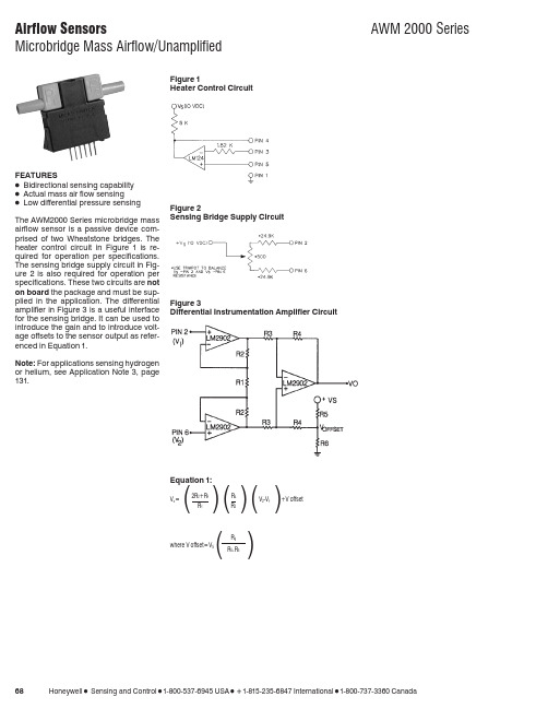
681-800-537-6945 USA 1-815-235-6847 International1-800-737-3360 CanadaFEATURESɀBidirectional sensing capability ɀActual mass air flow sensingɀLow differential pressure sensing The AWM2000 Series microbridge mass airflow sensor is a passive device com-prised of two Wheatstone bridges. The heater control circuit in Figure 1is re-quired for operation per specifications.The sensing bridge supply circuit in Fig-ure 2 is also required for operation per specifications. These two circuits are not on board the package and must be sup-plied in the application. The differential amplifier in Figure 3 is a useful interface for the sensing bridge. It can be used to introduce the gain and to introduce volt-age offsets to the sensor output as refer-enced in Equation 1.Note: For applications sensing hydrogen or helium, see Application Note 3, page 131.Figure 1Heater Control CircuitFigure 2Sensing Bridge Supply CircuitFigure 3Differential Instrumentation Amplifier CircuitEquation 1:V o ⍧2R 2+R 1R 4V 2-V 1+V offset()()()R 1R 3where V offset ⍧V S()R 6R 6+R 51-800-537-6945 USA 1-815-235-6847 International 1-800-737-3360 Canada 691. Output Voltage is ratiometric to supply voltage.2. Temperature shifts when sensing differential pressure correlates to the density change of the gas over temperature.See Application Note 1.3. Maximum allowable rate of flow change to prevent damage: 5.0 SLPM/1.0 sec.MOUNTING DIMENSIONS (for reference only)Airflow701-800-537-6945 USA 1-815-235-6847 International 1-800-737-3360 CanadaOUTPUT FLOW VS INTERCHANGEABILITY (Note 1)Performance Characteristics @10.0 ±0.01VDC, 25°C AWM2100V AWM2150VAWM2200V(Note 2)AWM2300V Press.Flow Nom.Tol.Press.Flow Nom.Tol.Flow Press.Nom.Tol.Press.Flow Nom.Tol.mBar sccm mV±mVȖBar sccm mV±mVsccm ⍯H 2O mV±mVmBar sccm mV±mV0.4920044.50 4.25533014.0 2.5120 4.0031.75 3.50 3.4100055.50 3.700.3515038.75 3.0036209.5 1.590 3.0026.75 2.50 2.480052.90 3.500.2110030.00 1.501710 5.0 1.560 2.0020.00 1.20 1.865050.00 2.500.095016.50 2.509.85 2.5 1.030 1.0011.20 1.800.8340042.50 3.000.000.00 1.007.44 2.0 1.000.000.001.000.3120029.20 3.20−0.09−50−16.50 4.50 6.23 1.5 1.0−30−1.00−11.20 3.0000.00 1.00−0.21−100−30.00 5.0052 1.0 1.0−60−2.00−20.00 3.30−0.31−200−28.9015.00−0.35−150−38.807.65 2.510.50.8−90−3.00−26.75 5.30−0.83−400−41.2026.00−0.49−200−44.509.75000.00.6−120−4.00−31.757.00−1.6−600−48.2029.50−9.8−5−2.5 2.0−2.4−800−52.2032.50−53−30−14.05.0−3.4−1000−55.0036.00Notes:1.Numbers in BOLD type indicate calibration type, mass flow or differential pressure.Tolerance values apply to calibration type only.2.Differential pressure calibrated devices are not recommended for flow e flow calibrated devices for flow measurement.OUTPUT CURVES。
电动二通阀

电动二通阀电动二通阀是专供中央空调风机盘管的配套产品,由驱动器与阀体两部分组成,驱动器由一个同步电机驱动,具备弹簧复位及手动开阀杠杆操纵功能。
阀体部分采用活塞式结构。
电动阀可与温控器配套使用,由温控器控制电动阀电机,使阀门开或关,实现管道冷水或热水的通或断,再通过风机盘管送风,以实现温度的自动调节。
目录• 电动二通阀-应用范围及产品特点• 工作原理• 电动二通阀-调试•电动二通阀技术参数驱动器规格型号和技术参数铜阀规格型号和技术参数电动二通阀安装尺寸电动二通阀-应用范围及产品特点1.用于控制冷水或热水空调系统管道的开启或关闭,达到控制室温之目的。
2.驱动器由单项磁滞同步马达驱动,阀门弹簧复位,阀门不工作时处于常闭状态,当需要工作时,由温控器提供一个开启信号,使电动阀接通交流电源而动作。
3..开启阀门,冷冻水或热水进入风机盘管,为房间提供冷气或暖气,当室温达到温控器设定值时,温控器令电动阀断电,复位弹簧使阀门关闭,从而截断进入风机盘管的水流,通过阀门关闭和开启,使室温始终保持在温控设定的温度范围内。
4..ZYFT系列电动阀的驱动器与阀门采用螺纹连接方式,可在阀门安装之后,再安装驱动器。
现场装配,接线灵活、方便。
驱动器之平面设计可以贴近墙面安装,占用空间小,产品可靠耐用,工作噪音低,并能在隐蔽式风机盘管装置内常出现的高温高湿环境可靠工作。
执行器选用铸铝支架及塑料外壳,体积小、重量轻★选用永磁同步电机,并带有磁滞离合机构,具有可靠的自我保护功能★适合多种控制信号:增量(浮点)、电压(0~10V)、电流(4~20mA)★具有0~10V或4~20mA反馈信号(选配)★传动齿轮采用金属齿轮,大大提高了驱动器的使用寿命★功耗低、输出力大、噪音小★阀体有铸铜、铸铁、铸钢、不锈钢多种材质可供选择,以适合不同工作介质及温度的要求★阀体有螺纹连接和法兰连接两种,安装方便,其构造符合IEC国际标准★阀体结构形式有两通阀(单座)、两通平衡阀(平衡式)、三通合流和三通分流阀它分为直动式和先导式2种。
各种球磨机的详细资料配比
MQG2400×3000 干湿 20 15.5 ≤25 0.043-0.8 8-15 YR4004-8 250 9128×4956×4018 65.88
内衬:石衬 δ=140 橡胶衬 δ=60
机重(不含衬):19000kg
型号:QM3500×6000P
筒体容积:57.7 m3
工作转速:12.5r/min
辅助转速:1.5r/min
主电机型号、功率:Y315L2-6 110kW
辅助电机型号、功率:Y200L-6 18.5kW
MQG1500×3000 干湿 28.8 8.0 ≤25 0.074-0.4 2.5-8.0 JR125-8 95 7604×3135×2658 17
MQG1500×3500 干湿 28.8 8.5 ≤25 0.074-0.4 3.0-8.5 YR280M-8 75 8104×3135×2658 19.5
MQG1200×1200 干湿 35 2.4 ≤25 0.074-0.8 2.0-3.0 Y250M-8 30 5520×2800×2550 11.4
MQG1200×1600 干湿 32 2.5 ≤25 0.074-0.8 2.0-3.6 Y225S-8 18.5 4099×2155×1855 8.8
MQG1830×5500 干湿 24.5 14.0 ≤25 0.043-0.8 6.0-10 JR136-8 180 10820×4685×3750 34.5
MQG1830×6400 干湿 24.5 16.0 ≤25 0.043-0.8 8.0-10.0 JR137-8 210 11720×4685×3750 36
一氧化碳传感器说明文档

MQ-4气体传感器特点* 对甲烷,天然气有很高的灵敏度*对乙醇,烟雾的灵敏度很低* 快速的响应恢复特性. * 长期的使用寿命和可靠的稳定性* 简单的驱动电路应用用于家庭,工业的甲烷,天然气的探测装置规格A. 标准工作条件符号参数名称技术条件备注Vc 回路电压≤15V AC or DC V H 加热电压 5.0V±0.2V AC or DC R L 负载电阻可调R H 加热电阻 31Ω±3Ω室温P H 加热功耗≤900mWB. 环境条件符号参数名称技术条件备注Tao 使用温度-10℃-50℃Tas 储存温度-20℃-70℃Rh相对湿度小于 95%RhO2 氧气浓度21%(标准条件)氧气浓度会影响灵敏度特性最小值大于2%C. 灵敏度特性符号参数名称技术参数备注Rs 敏感体表面电阻10KΩ- 60KΩ(5000ppm CH4)α(1000ppm/ 5000ppm CH4) 浓度斜率≤0.6标准工作条件温度: 20℃±2℃ Vc:5.0V±0.1V相对湿度: 65%±5% Vh: 5.0V±0.1V 预热时间不少于24小时适用范围:300-10000ppm 甲烷,天然气。
D. 结构,外形,测试电路MQ-4气敏元件的结构和外形如图1所示(结构 A 或 B), 由微型AL 2O 3陶瓷管、SnO 2 敏感层,测量电极和加热器构成的敏感元件固定在塑料或不锈钢制成的腔体内,加热器为气敏元件提供了必要的工作条件。
封装好的气敏元件有6只针状管脚,其中4个用于信号取出,2个用于提供加热电流。
测量电路如图2所示E. 灵敏度特性曲线图3 MQ-4型气敏元件的灵敏度特性图.2结构B结构A灵敏度调整:MQ-4型气敏元件对不同种类,不同浓度的气体有不同的电阻值。
因此,在使用此类型气敏元件时,灵敏度的调整是很重要的。
我们建议您用5000ppm 甲烷校准传感器。
当精确测量时,报警点的设定应考虑温湿度的影响。
新版中分2000说明书

保证仪器主机外壳接地良好。
—ii—
目录
操作安全 .................................................................... i
目 录 ....................................................................... I
— II—
中分 2000 气相色谱 仪说明书
第 1 章 仪器简介
中分 2000 系列气相色谱仪是新一代电力行业专用型气相色谱仪。 该系列仪器采用新型全集成混合信号单片机和大显示屏汉字显示技 术。测量精度高,操作简单,为广大电力试验工作者提供了一套性能 先进、实用性强、操作简便、性能稳定的气相色谱仪,是开展变压器 油色谱分析必备的分析设备。
紧急情况下的关机步骤
当出现紧急情况而需立即关机时,请按下述步骤操作: 关 闭 中 分 2000 色 谱 仪 主 机 电 源 开 关 ( 开 关 扳 至 OFF 位 置 )。 关闭所有辅助设备的电源开关。 关闭所有气体钢瓶总阀。 拔下仪器电源插头。 紧急情况完全排除后,再重新开启仪器。如果需要帮助,请 与我公司售后服务中心联系。
—i—
安全注意事项
本气相色谱仪是用于变压器油色谱分析的专用仪器。为了保证仪 器的操作安全,请遵守下列注意事项:
严格遵守本说明书所列出的操作步骤、警告和注意事项。 请 按 照 仪 器 的 设 计 用 途 使 用 仪 器 ,请 不 要 自 行 拆 卸 、改 装 仪 器 。 仪器需要维修时请与我公司售后服务中心联系。
EN中文版
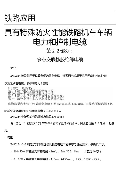
铁路应用具有特殊防火性能铁路机车车辆电力和控制电缆第2-2部分:多芯交联橡胶绝缘电缆简介EN50264涉及到用于铁路车辆的系列电缆,该系列电缆属于采用无卤材料的护套以及无护套电缆。
该标准分为5部分:括减少环境温度和安装类型因素)见EN50343oEN50264中涉及的特殊测试方法见EN50305o第1部分“一般要求”对EN50264做出了更详尽的介绍,因此应与第2-2部分一起使用。
1.范围EN50264-2-2规定了对下列型号及额定电压下的单芯电缆的要求、结构及尺寸。
•300/500V屏蔽或无屏蔽电缆(lmm\ 1.5mm2和2. 5mm:, 2芯到40芯);•0. 6/lkV屏蔽或无屏蔽电缆(1.5mm:到50mm,, 2芯、3芯和4芯)。
注:并非每个类型都规定J'导线尺寸或线芯数目所有的电缆采用5类镀锡铜线,符合EN60228的规定,且为无卤绝缘和无卤护套。
这些电缆用于铁路机车固定布线,或者操作时会碰到极限挠度的布线。
要求连续导线温度不超过90°C,在5秒内,短路条件下最大温度为200°C。
发生火灾时,电缆在最大允许火焰传播(火焰蔓延),最大允许烟雾及有毒气体释放等方面具有特殊的性能。
EX50264-2-2应与第1部分“一般要求” 一起使用。
2.引用标准以下引用的文件对于实施本文件是必不可少的。
凡注日期的引用文件,最新版不适用于本标准。
不注日期的引用文件,其最新版(包括任何修订)适用于本标准。
EN10002-1金属材料一拉伸测试一室温条件下试验方法EN50264-1铁路应用一具有特殊防火性能铁路机车车辆动力和控制电缆第1部分:一般要求EN50266-2-4电缆在火焰条件下的通用试验方法一垂直安装的成束电线或电缆的垂直火焰蔓延试验第2-4部分:试验步骤一C类EN50266-2-5电缆在火焰条件下的通用试验方法一垂直安装的成束电线或电缆的垂直火焰蔓延试验第2-5部分:试验步骤一小电缆一D 类EN50305:2002铁路应用-具有特殊防火性能铁路机车车辆电缆-测试方法EX50334电缆芯线识别用符号标记EN60228 电缆的导体(IEC60228)EN60332-1-2电缆和光缆在火焰条件下的试验方法第1-2部分:单根绝缘电线电缆垂直火焰蔓延试验一lkW预混合火焰(IEC660332-1-2) EN608U-l-l:1995电缆和光缆绝缘和护套材料的一通用试验方法第1~1部分:一般应用一厚度和外形尺寸测量一机械性能试验(IEC60811-l-l:1993)EN60811-1-2:1995电缆绝缘和护套材料的一通用试验方法第1-2部分:一般应用一热老化试验 (IEC60811-l-2:1985+Al : 1989+corr.Mayl986)EN60811-1-3:1995电缆和光缆绝缘和护套材料的一通用试验方法第1-3部分:一般应用一密度测定方法一吸水试验一回缩试验(IEC60811-1-3:1993)EN60811-1-4:1995电缆和光缆绝缘和护套材料的一通用试验方法第1-4部分:一般应用一低温试验(IEC60811-1-4:1985+A11993+corr.May1986 ) EN60811-2-l:1998电缆和光缆绝缘和护套材料的一通用试验方法第2-1部分:一般应用一橡胶混合物测试方法一耐臭氧试验、热延伸试验和浸矿物油试验(IEC60811-2-1:1998)EN61034-2电缆在特定条件下燃烧的烟密度测定第2部分:试验步骤和要求(IEC61034-2)HD308电缆与软线的芯线标记3.定义EN50264-1的定义适用于木标准。
六亚甲基四胺

生殖毒性 生殖毒性 - 产品 致畸性 - 产品
: 无数据资料 : 无数据资料
特定目标器官系统毒性-单次 : 无数据资料 接触 - 产品
特定目标器官系统毒性-多次 : 无数据资料 接触 - 产品
重复剂量中毒- 产品
: 无数据资料
吸入危险 吸入毒性 - 产品
: 无数据资料
十二 生态学信息 生态毒性
一 化学品及企业标识 化: HEXAMETHYLENETETRAMINE GRANULR : 137602
公司
: 亚什兰(中国)投资有限公司 中国 上海 中山南二路 1089 号 徐汇苑大厦 18 层 邮政编码:200030
Company
: Ashland (China) Holdings Co., Ltd China Shanghai 1089 Zhongshan rd(s.)18th Floor Xuhuiyuan Building Zip Code:200030
十稳定性和反应性 避免接触的条件
: 备注: 热,火焰和火花。
7
禁配物备注: 暴露在潮湿中。 热,火焰和火花。
: 备注: 酸 强氧化剂
: 注释: 氨水 二氧化碳和一氧化碳 甲醛 氮氧化物 氢氰酸
: 注释: 在推荐的贮存条件下是稳定的。
不发生危险的聚合反应。 粉尘在空气中可能会形成化学文摘编号(CAS No.) Index number deleted RTECS number deleted EINECS number deleted
: 100-97-0
有害物成分 化学品名称 环己四‘胺 四急救措施 一般的建议
如果吸入
在皮肤接触的情况下 在眼睛接触的情况下
没有已知的国家规定的暴露极限。
《热质交换原理与设备》习题答案第

第一章???绪论1、答:分为三类。
动量传递:流场中的速度分布不均匀(或速度梯度的存在);热量传递:温度梯度的存在(或温度分布不均匀);质量传递:物体的浓度分布不均匀(或浓度梯度的存在)。
2、解:热质交换设备按照工作原理分为:间壁式,直接接触式,蓄热式和热管式等类型。
●间壁式又称表面式,在此类换热器中,热、冷介质在各自的流道中连续流动完成热量传递任务,彼此不接触,不掺混。
●直接接触式又称混合式,在此类换热器中,两种流体直接接触并且相互掺混,传递热量和质量后,在理论上变成同温同压的混合介质流出,传热传质效率高。
●蓄热式又称回热式或再生式换热器,它借助由固体构件(填充物)组成的蓄热体传递热量,此类换热器,热、冷流体依时间先后交替流过蓄热体组成的流道,热流体先对其加热,使蓄热体壁温升高,把热量储存于固体蓄热体中,随即冷流体流过,吸收蓄热体通道壁放出的热量。
●热管换热器是以热管为换热元件的换热器,由若干热管组成的换热管束通过中隔板置于壳体中,中隔板与热管加热段,冷却段及相应的壳体内穷腔分别形成热、冷流体通道,热、冷流体在通道内横掠管束连续流动实现传热。
3、解:顺流式又称并流式,其内冷、热两种流体平行地向着同方向流动,即冷、热两种流体由同一端进入换热器。
●逆流式,两种流体也是平行流体,但它们的流动方向相反,即冷、热两种流体逆向流动,由相对得到两端进入换热器,向着相反的方向流动,并由相对的两端离开换热器。
●叉流式又称错流式,两种流体的流动方向互相垂直交叉。
●混流式又称错流式,两种流体的流体过程中既有顺流部分,又有逆流部分。
●顺流和逆流分析比较:在进出口温度相同的条件下,逆流的平均温差最大,顺流的平均温差最小,顺流时,冷流体的出口温度总是低于热流体的出口温度,而逆流时冷流体的出口温度却可能超过热流体的出口温度,以此来看,热质交换器应当尽量布置成逆流,而尽可能避免布置成顺流,但逆流也有一定的缺点,即冷流体和热流体的最高温度发生在换热器的同一端,使得此处的壁温较高,为了降低这里的壁温,有时有意改为顺流。
中文四版-SMC样本
2.5, 4
CAT.C06-02A
6, 10, 15
CAT.C06-02A
6, 10, 16
CAT.C04-01A
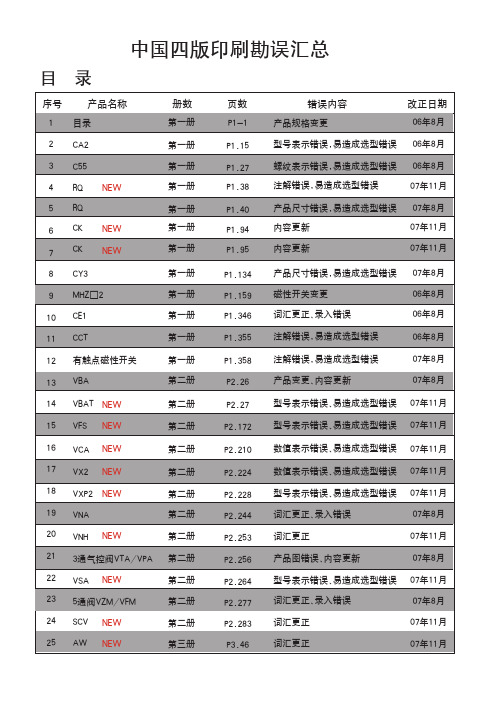
错误内容 产品规格变更
改正日期 06年8月
型号表示错误,易造成选型错误 06年8月
螺纹表示错误,易造成选型错误 06年8月
注解错误,易造成选型错误
07年11月
产品尺寸错误,易造成选型错误 07年8月
内容更新
07年11月
内容更新
07年11月
产品尺寸错误,易造成选型错误 磁性开关变更 词汇更正、录入错误
CAT.ES20-152B CAT.ES20-177A CAT.E256A CAT.ES20-179B CAT.E216B CAT.ES20-95B CAT.ES20-157B P-1991-6 CAT.ES20-160A CAT.E204A CAT.ES20-159A CAT.ES20-159A CAT.ES20-159A CAT.ES20-147A
9
f
B1
h+
□C
ZZ + + 行程
□B
A KF N H
S + 行程 ZZ + 行程
N M
(mm)
缸径 行程范围 (mm)
A AL □B B1 □C D E F G H1
J
(mm) 无防护套 带防护套
无防护套
带防护套
K KA M MM N P S
H ZZ e f h
信号发生器MFG-2000使用手册(中)
多通道函数信号发生器MFG-2000系列使用手册固纬料号NO.82MF32K000EF1ISO-9001认证企业2015.07本手册所含资料受到版权保护,未经固纬电子实业股份有限公司预先授权,不得将手册内任何章节影印、复制或翻译成其它语言。
本手册所含资料在印制之前已经过校正,但因固纬电子实业股份有限公司不断改善产品,所以保留未来修改产品规格、特性以及保养维修程序的权利,不必事前通知。
固纬电子实业股份有限公司台湾台北县土城市中兴路7-1号目录安全说明 (7)产品介绍 (11)主要特点 (12)面板介绍 (14)显示 (24)设置信号发生器 (25)快速操作 (27)如何使用数字输入 (29)如何使用帮助菜单 (30)顯示區域的分配 (32)选择波形 (33)调制 (35)扫描 (44)脉冲串 (46)ARB (48)工具栏 (52)菜单树 (53)默认设置 (71)操作 (73)CH1/CH2通道 (75)RF通道 (89)Pulse 通道 (100)功率放大器 (111)3调制 (114)幅值调制(AM) (117)幅移键控(ASK) (124)频率调制(FM) (130)频移键控(FSK) (137)相位调制(PM) (143)相移键控(PSK) (150)脉冲宽度调制(PWM) (155)总和调制(SUM) (161)频率扫描 (168)脉冲串模式 (177)辅助系统功能设置 (187)存储和调取 (188)选择远程接 (192)系统和设置 (196)信道功能设置 (200)双通道操作 (204)任意波形 (209)插入内置波形 (210)显示任意波形 (212)编辑任意波形 (219)输出任意波形 (228)存储/调取任意波形 (230)远程接口 (239)确立远程连接 (240)4网络浏览器控制界面 (245)指令列表 (253)系统指令 (257)状态寄存器指令 (261)接口设置指令 (264)应用指令 (265)输出指令 (272)脉冲设置指令 (282)幅值调制(AM)指令 (286)振幅键控(ASK)指令 (291)频率调制(FM)指令 (294)频移键控(FSK)指令 (299)相位调制(PM)指令 (302)相位键控(PSK)指令 (306)总和调制(SUM)指令 (309)脉宽调制(PWM)指令 (314)频率扫描(Sweep)指令 (318)脉冲串模式(Burst)指令 (328)任意波形(ARB)指令 (339)计频器(Counter)指令 (347)相位 (Phase)指令 (349)耦合(Couple)指令 (350)存储和调取指令 (353)错误信息 (355)SCPI状态寄存器 (368)附录 (374)MFG-2000系列规格 (374)EC符合性声明书 (384)GLOBL HEADAQARTERS (385)5任意波内建波形 (386)索引 (398)67安全说明本章节包含操作和存储信号发生器时必须遵照的重要安全说明。
SMC中文四版电子样本第一册(执行元件)2of6
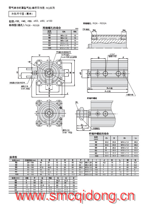
杆侧 气缸通口TP
⑦
⑧
⑥
R□LQB 缸径 -B□ 后退方向锁,右侧配管(虚线为左侧配管) . . = = .TH .TH ⑤ ① ④ ② ③
= .Max. T1
杆侧 气缸通口TP
无杆侧 气缸通口TP
⑥ ⑧ ⑦
= .Max. T2
= .T3
.
.
.
带旁通管路气缸的构成
序号 1 2 3 4 5 6 7 8 名 称 带锁带气缓冲的薄型气缸 PT弯头 节流阀 PT三通 金属体速度控制阀 弯头 旁通管 防火花罩 数量 1 1 1 1 2 2 1 2 型号
47.5 57.5 67.5
19 26 26
!"#$ !"=E
%/ F
!": RQ
安装件型号 CQ-L032
RQL·RDQL
63 80 100
CQ-L040 CQ-L050 CQ-L063 CQ-L080 CQ-L100 30~100 40~100 40~100 81.2 95 111 55 63.5 76 29 33.5 42 18 20 22 43.5 53.5 53.5 11 13 13
旁通配管 无记号 无
R
带旁通配管右配管 (防止落下)
L 带旁通配管左配管 (防止落下)
(
外形尺寸图 (毫米) ¿32(非常停止)
两端螺孔/R□LQA32
PL锁开放通口 加压状态下锁开放 55 22.5 9
锁方向 F 前进方向锁 B 后退方向锁
非 常 停 止
*配管的左右,是从杆侧观察。
*1台气缸应订购2只脚座。 *脚座型、法兰型附本体安装螺钉。 *双耳环型附耳环用销轴,弹性挡圈, 本体安装螺钉及垫圈。
双杆式气帘机技术数据表说明书

Pneumatic Specifications Imperial Metric Pressure Operating Range 40-100 psi 3-7 bar Cylinder Type Double ActingDynamic Seals Internally Lubricated Buna-N Valve Required to Operate 4-way, 2-position Air Quality RequirementsAir Filtration 40 Micron or Better Air Lubrication Not Necessary *Air Humidity Low Moisture Content (dry)Temperature Operating RangeBuna-N Seals (standard) -30°~180° F -35°~80° C Viton ®Seals (optional) -20°~300° F -30°~150° C Maintenance Specifications Expected LifeNormal Application 5 million cycles w/ Preventative Maintenance 10+ million cycles *Field Repairable Yes Seal Repair Kits Available Yes -W Option Shaft Wiper SpecificationsWiper Material 90 Durometer Urethane Temperature Rating (Wiper Only) -65°~275° F -54°~135° C Compatible Chemicals water, coolant, petroleum oils, silicone, lubricants, dilute acids & alkalis, hydraulic fluid, transmission fluid Non-Compatible Chemicals Ozone, ketones, strong acids, brake fluidExample Applications Grinding dust, machine chips & coolant, paper dust, washdown Application RestrictionsApplications where mechanism lubricant could cause contamination (use -W Shaft Wiper Option in this case)*Addition of lubrication will greatly increase service lifeTechnical Specifications:Grippers can be mounted & operated in any directionFingers attach with screws and locate on jaws withdowel pinsMounting Information:Parallel Grippers-DPW DIRECTCONNECT ™Wide Body SeriesG• DIRECTCONNECT ™Connectivity:DIRECTCONNECT ™Tapped and Dowel mounting on body.• Large or Wide Parts:Wide body design provides secure gripping of large & wide parts.•Multiple air port positions:Tapped air ports on top and front are standard.• Manifold Air Porting:Top air ports can be manifold o-ring sealed.• Inductive Sensor Flexibility:Mount either 3mm or 4mm Inductive sensors with the same bracket (3mm only on DPW-250).• M agnetoresistive Sensing:Full range adjustable Magnetoresistive Sensors. Magnet supplied standard.• Long Finger Applications:Jaw support thru the length of the body allows for long fingers to be attached to jaws.• Thru Jaw Mounting:Offers a wider variety of mounting applications for jaws.• Shaft Wiper Option:Rugged urethane shaft wipers seal the unit against harsh environments. Designed to be used in machine coolant and metal chip environment applications.• Multiple Strokes: All gripper sizes are available in 2 different strokes.• Non-synchronous motion: The unit can be made non-synchronous providing independent jaw motion allowing the gripper to pick or place at a point other than its center.Thru mounting on inside of jaws to allow for alternatefinger mounting Jaw design allows for simplified mounting of fingersBody mounts on top with screws and locates with slip fit dowel pin holes for accuracySymmetrical mounting pattern on jaws allows for multiplefinger orientation1.196D P W SE R I E STMC o u r t e s y o f C M A /F l o d y n e /H y d r a d y n e ▪ M o t i o n C o n t r o l ▪ H y d r a u l i c ▪ P n e u m a t i c ▪ E l e c t r i c a l ▪ M e c h a n i c a l ▪ (800) 426-5480 ▪ w w w .c m a f h .c o m1.197D P W SE R I E SSealed Design (-W option)Urethane shaft wipers prevent against dirty environments (machining chips & coolant, grinding dust, paper millenvironments, etc.)Thru-Jaw MountingC’bores on inside of jaws for thru mounting to increase range ofapplicationsSensorMounting SlotsStandard mounting slots for magneto resistive and inductive sensors (sensors sold separately)Square-Faced JawsAllow for a symmetrical, multi-positional mounting pattern for simplified finger design and increased range of applicationsMultiple Air Port Locations2 standard airport location(front & top)Quality ComponentsHardened precision stainless steel shafting for wear resistance andlong lifeSuperior Jaw SupportEach jaw is supported by 2 shafts that extend the entire length of the body and are guided by 2 oil impregnated bronze bushings pershaftMagneto ResistiveSensorsAn alternative option to inductive sensors (magnets supplied standard)Dowel HolesSlip fit dowel pin holes in body and jawsSimplified Finger MountingLarge jaw configuration allows for simplified finger mountingOptional Non-SynchronousOperation• Two shafts, one with a rack cut into it, are securely fastened to each of the jaws and ARE supported through the length of the body.• Two double acting opposed pistons provide power to the jaws.• The rack shafts of each jaw slide in opposite directions of one another and are synchronized by a piston gear.• This gripper is suitable for internal or external gripping and can be mounted in any orientation.Pressure ExhaustOpen PositionProduct FeaturesOperating PrincipleU.S Patent #5,163,729 Designed, manufactured and assembled in the USAPressureExhaust End PlateJawBodyUrethane Shaft Wipers(-W Option)PistonBearingPinion Gear and Radial BearingRack ShaftClosed PositionMounting PatternsDIRECTCONNECT ™Tapped & Dowel mounting surfaceon top of bodyEnd of Stroke CushionsReduce shock of fully open and close strokesHigh TemperatureOptional Viton ®seals are available for high temperature applicationsSee Page1.198Style -DPW Parallel GripperSize -250M-1 250M-1Stroke: 0.75 in. 19.1 mmGrip Force: 50 lbs. 222 NWeight: 0.662 lbs. 0.30 KgSee Page1.200Style -DPW Parallel GripperSize -250M-2Style: 250M-2Stroke: 1.25 in. 31.8 mmGrip Force: 50 lbs. 222 NWeight: 0.856 lbs. 0.39 KgSee Page1.202Style -DPW Parallel GripperSize -375M-1Style: 375M-1Stroke: 1.00 in. 25.4 mmGrip Force: 100 lbs. 445 NWeight: 1.80 lbs. 0.81 KgSee Page1.204Style -DPW Parallel GripperSize -375M-2Style: 375M-2Stroke: 2.00 in. 50.8 mmGrip Force: 100 lbs. 445 NWeight: 2.66 lbs. 1.20 KgSee Page1.206Style -DPW Parallel GripperSize -500M-1Style: 500M-1Stroke: 1.50 in. 38.1 mmGrip Force: 180 lbs. 800 NWeight: 3.27 lbs. 1.48 KgStyle -DPW Parallel GripperSize -500M-2Style: 500M-2Stroke: 2.50 in. 63.5 mmGrip Force: 180 lbs. 800 NWeight: 4.39 lbs. 2.0 KgShown with -W Shaft Wiper OptionShown with -W Shaft Wiper OptionShown with -W Shaft Wiper OptionShown with -W Shaft Wiper OptionShown with -W Shaft Wiper OptionShown with -W Shaft Wiper OptionPiston ShaftShaftMagnetManifold Air PortsTop air ports can be O-Ring manifold sealed to eliminateair linesCombined 3mm and 4mm Inductive SensorMountingAllows for either 3 or 4mmInductive sensors (3mm only on DPW-250)See Page1.208C o u r t e s y o f C M A /F l o d y n e /H y d r a d y n e ▪ M o t i o n C o n t r o l ▪ H y d r a u l i c ▪ P n e u m a t i c ▪ E l e c t r i c a l ▪ M e c h a n i c a l ▪ (800) 426-5480 ▪ w w w .c m a f h .c o m1.198.3759.5[M3 X 5 DP.][[M3 X 5 DP.](CLOSE PORT)10.52X .166 4.2SENSOR ENTRANCE SLOT 7.92X .227 5.82X .246C L[M4 X 8DP.][4 H7 X 5DP.]37.6PARALLEL GRIPPERS DPW-250M-1DIRECTCONNECT WIDE BODY SERIESNOTE: DIRECTCONNECT DIMENSIONS ARE SHOWN IN BLUEC o u r t e s y o f C M A /F l o d y n e /H y d r a d y n e ▪ M o t i o n C o n t r o l ▪ H y d r a u l i c a t i c ▪ E l e c t r i c a l ▪ M e c h a n i c a l ▪ (800) 426-5480 ▪ w w w .c m a f h .c o m1.199D P W SE R I E SPARALLEL GRIPPERS DPW-250M-1DIRECT CONNECT WIDE BODY SERIESSpecifications Total Rated Grip Force F @ 100 psi, 7 bar............. 50 lbs. 222 N Stroke...................................................................... 0.75 in. 19.1 mm Pressure Range....................................................... 40-100 psi 3-7 bar Cylinder Bore Ø....................................................... 0.625 in. 15.9 mm Displacement.......................................................... 0.023 in 3. 3.8 cm 3Weight..................................................................... 0.662 lbs. 0.30 Kg Temperature Range: Standard Seals...................... -30°~180° F -35°~80° C Viton ® Seals........................... -20°~300° F -30°~150° C Actuation ................................................................ 0.12 sec. 0.12 sec.Accuracy................................................................. ±0.003 in. ±0.08 mm Repeatability............................................................ ±0.001 in. ±0.03 mm Valve required to actuate........................................ 4-way, 2-positionMaximum Tensile T 60 lbs. [267 N ] 12 lbs. [53 N] Maximum Compressive C 60 lbs. [267 N] 12 lbs. [53 N]Maximum Moment M x 120 in.-lbs. [14 Nm] 24 in.-lbs. [3 Nm]Maximum Moment M y 180 in.-lbs.[20 Nm] 36 in.-lbs.[4 Nm]Maximum Moment M z 120 in.-lbs.[14 Nm] 24 in.-lbs.[3 Nm]Capacities are per set of jaws and are not simultaneous111896745220N EFFECTIVE FINGER LENGTH - LF I NG E R F O R C E - F /2255075102127 mmGRIP FORCE PER FINGERC o u r t e s y o f C M A /F l o d y n e /H y d r a d y n e ▪ M o t i o n C o n t r o l ▪ H y d r a u l i c a t i c ▪ E l e c t r i c a l ▪ M e c h a n i c a l ▪ (800) 426-5480 ▪ w w w .c m a f h .c o m1.200.3759.5[(CLOSE PORT)16.9(JAW)2X .166 4.2 SENSOR ENTRANCE SLOT7.92X .2897.3.24 6C L[M4 X 8DP.][37.6PARALLEL GRIPPERS DPW-250M-2DIRECTCONNECT WIDE BODY SERIESNOTE: DIRECTCONNECT DIMENSIONS ARE SHOWN IN BLUEC o u r t e s y o f C M A /F l o d y n e /H y d r a d y n e ▪ M o t i o n C o n t r o l ▪ H y d r a u l i c a t i c ▪ E l e c t r i c a l ▪ M e c h a n i c a l ▪ (800) 426-5480 ▪ w w w .c m a f h .c o m1.201D P W SE R I E SPARALLEL GRIPPERS DPW-250M-2DIRECT CONNECT WIDE BODY SERIESTotal Rated Grip Force F @ 100 psi, 7 bar............. 50 lbs. 222 N Stroke...................................................................... 1.25 in. 31.8 mm Pressure Range....................................................... 40-100 psi 3-7 bar Cylinder Bore Ø....................................................... 0.625 in. 15.9 mm Displacement.......................................................... 0.383 in 3. 6.3 cm 3Weight..................................................................... 0.856 lbs. 0.39 Kg Temperature Range: Standard Seals...................... -30°~180° F -35°~80° C Viton ® Seals........................... -20°~300° F -30°~150° C Actuation ................................................................ 0.14 sec. 0.14 sec.Accuracy................................................................. ±0.003 in. ±0.08 mm Repeatability............................................................ ±0.001 in. ±0.03 mm Valve required to actuate........................................ 4-way, 2-positionMaximum Tensile T 60 lbs. [267 N ] 12 lbs. [53 N] Maximum Compressive C 60 lbs. [267 N] 12 lbs. [53 N]Maximum Moment M x 120 in.-lbs. [14 Nm] 24 in.-lbs. [3 Nm]Maximum Moment M y 180 in.-lbs.[20 Nm] 36 in.-lbs.[4 Nm]Maximum Moment M z 120 in.-lbs.[14 Nm] 24 in.-lbs.[3 Nm]Capacities are per set of jaws and are not simultaneous111896745220N F I N G E R F O R C E - F /2255075102127 mmGRIP FORCE PER FINGERC o u r t e s y o f C M A /F l o d y n e /H y d r a d y n e ▪ M o t i o n C o n t r o l ▪ H y d r a u l i c a t i c ▪ E l e c t r i c a l ▪ M e c h a n i c a l ▪ (800) 426-5480 ▪ w w w .c m a f h .c o m1.20219.1[M5 X 7 DP.][5 H7 X 5 [M5 X 7 DP.](CLOSE PORT)13.04X .166 4.2 SENSOR ENTRANCE SLOT17.82X .262 6.7[M3 X 4 DP.].18 5C L[54.0PARALLEL GRIPPERS DPW-375M-1DIRECTCONNECT WIDE BODY SERIESNOTE: DIRECTCONNECT DIMENSIONS ARE SHOWN IN BLUEC o u r t e s y o f C M A /F l o d y n e /H y d r a d y n e ▪ M o t i o n C o n t r o l ▪ H y d r a u l i c a t i c ▪ E l e c t r i c a l ▪ M e c h a n i c a l ▪ (800) 426-5480 ▪ w w w .c m a f h .c o m1.203D P W SE R I E SPARALLEL GRIPPERS DPW-375M-1DIRECT CONNECT WIDE BODY SERIESSpecifications Total Rated Grip Force F @ 100 psi, 7 bar............. 100 lbs. 445 N Stroke...................................................................... 1.00 in. 25.4 mm Pressure Range....................................................... 40-100 psi 3-7 bar Cylinder Bore Ø....................................................... 0.938 in. 23.8 mm Displacement.......................................................... 0.690 in 3. 11.3 cm 3Weight..................................................................... 1.80 lbs. 0.81 Kg Temperature Range: Standard Seals...................... -30°~180° F -35°~80° C Viton ® Seals........................... -20°~300° F -30°~150° C Actuation ................................................................ 0.16 sec. 0.16 sec.Accuracy................................................................. ±0.003 in. ±0.08 mm Repeatability............................................................ ±0.001 in. ±0.03 mm Valve required to actuate........................................ 4-way, 2-positionMaximum Tensile T 120 lbs. [534 N ] 24 lbs. [107 N] Maximum Compressive C 120 lbs. [534 N] 24 lbs. [107 N]Maximum Moment M x 210 in.-lbs.[24 Nm] 42 in.-lbs.[5 Nm]Maximum Moment M y 300 in.-lbs.[34 Nm] 60 in.-lbs.[7 Nm]Maximum Moment M z 210 in.-lbs.[24 Nm] 42 in.-lbs.[5 Nm]Capacities are per set of jaws and are not simultaneous223 178 134 89 45 0lbs.N F I N G E R F O R C E - F /2 GRIP FORCE PER FINGER 02550178 mmWARNING!102 12715376 C o u r t e s y o f C M A /F l o d y n e /H y d r a d y n e ▪ M o t i o n C o n t r o l ▪ H y d r a u l i c a t i c ▪ E l e c t r i c a l ▪ M e c h a n i c a l ▪ (800) 426-5480 ▪ w w w .c m a f h .c o m1.20419.1[(CLOSE PORT)4X .166 4.2SENSORENTRANCESLOT2X .46211.7.18 5C L5 H7 X 5 DP.]54.0 PARALLEL GRIPPERS DPW-375M-2DIRECTCONNECT WIDE BODY SERIESNOTE: DIRECTCONNECT DIMENSIONS ARE SHOWN IN BLUECourtesyofCMA/Flodyne/Hydradyne▪MotionControl▪Hydraulicatic▪Electrical▪Mechanical▪(8)426-548▪www.cmafh.co m1.205D P W SE R I E SSpecifications Total Rated Grip Force F @ 100 psi, 7 bar............. 100 lbs. 445 N Stroke...................................................................... 2.00 in. 50.8mm Pressure Range....................................................... 40-100 psi 3-7 bar Cylinder Bore Ø....................................................... 0.938 in. 23.8 mm Displacement.......................................................... 1.382 in 3. 22.6 cm 3Weight..................................................................... 2.66 lbs. 1.20 Kg Temperature Range: Standard Seals...................... -30°~180° F -35°~80° C Viton ® Seals........................... -20°~300° F -30°~150° C Actuation ................................................................ 0.20 sec. 0.20 sec.Accuracy................................................................. ±0.003 in. ±0.08 mm Repeatability............................................................ ±0.001 in. ±0.03 mm Valve required to actuate........................................ 4-way, 2-positionPARALLEL GRIPPERS DPW-375M-2DIRECT CONNECT WIDE BODY SERIESMaximum Tensile T 120 lbs. [534 N ] 24 lbs. [107 N] Maximum Compressive C 120 lbs. [534 N] 24 lbs. [107 N]Maximum Moment M x 210 in.-lbs.[24 Nm] 42 in.-lbs.[5 Nm]Maximum Moment M y 300 in.-lbs.[34 Nm] 60 in.-lbs.[7 Nm]Maximum Moment M z 210 in.-lbs.[24 Nm] 42 in.-lbs.[5 Nm]Capacities are per set of jaws and are not simultaneous223 178 134 89 45 0lbs.N F I N G E R F O R C E - F /2 GRIP FORCE PER FINGER 02550178 mmWARNING!102 12715376 C o u r t e s y o f C M A /F l o d y n e /H y d r a d y n e ▪ M o t i o n C o n t r o l ▪ H y d r a u l i c a t i c ▪ E l e c t r i c a l ▪ M e c h a n i c a l ▪ (800) 426-5480 ▪ w w w .c m a f h .c o m1.206[5 H7 X 5 [M5 X 5 DP.](CLOSE PORT)19.119.24X .166 4.2 SENSOR SLOT18.8.47512.1(OPEN PORT).20 5C L[M6 X 13 DP.][6 H7 X8 DP.]51.00PARALLEL GRIPPERS DPW-500M-1DIRECTCONNECT WIDE BODY SERIESNOTE: DIRECTCONNECT DIMENSIONS ARE SHOWN IN BLUEC o u r t e s y o f C M A /F l o d y n e /H y d r a d y n e ▪ M o t i o n C o n t r o l ▪ H y d r a u l i c a t i c ▪ E l e c t r i c a l ▪ M e c h a n i c a l ▪ (800) 426-5480 ▪ w w w .c m a f h .c o m1.207D P W SE R I E SPARALLEL GRIPPERS DPW-500M-1DIRECT CONNECT WIDE BODY SERIESMaximum Tensile T 600 lbs. [2668 N ] 60 lbs. [267 N] Maximum Compressive C 600 lbs. [2668 N] 60 lbs. [267 N]Maximum Moment M x 600 in.-lbs.[68 Nm] 60 in.-lbs.[7 Nm]Maximum Moment M y 900 in.-lbs.[102 Nm] 90 in.-lbs.[10 Nm]Maximum Moment M z 600 in.-lbs.[68 Nm] 60 in.-lbs.[7 Nm]Capacities are per set of jaws and are not simultaneousSpecifications Total Rated Grip Force F @ 100 psi, 7 bar............. 180 lbs. 800 N Stroke...................................................................... 1.50 in. 38.1 mm Pressure Range....................................................... 40-100 psi 3-7 bar Cylinder Bore Ø....................................................... 1.250 in. 31.8 mm Displacement.......................................................... 1.841 in 3. 30.2 cm 3Weight..................................................................... 3.27 lbs. 1.48 Kg Temperature Range: Standard Seals...................... -30°~180° F -35°~80° C Viton ® Seals........................... -20°~300° F -30°~150° C Actuation ................................................................ 0.20 sec. 0.20 sec.Accuracy................................................................. ±0.003 in. ±0.08 mm Repeatability............................................................ ±0.001 in. ±0.03 mm Valve required to actuate........................................ 4-way, 2-position40035631226722317813489450lbs.NF I NG E R F O R C E - F /2GRIP FORCE PER FINGER517676102127330mm203229254279305152178C o u r t e s y o f C M A /F l o d y n e /H y d r a d y n e ▪ M o t i o n C o n t r o l ▪ H y d r a u l i c a t i c ▪ E l e c t r i c a l ▪ M e c h a n i c a l ▪ (800) 426-5480 ▪ w w w .c m a f h .c o m1.208(CLOSE PORT)19.131.918.8(OPEN PORT)C L[M6 X 13 DP.][ 6 H7 X 8 DP.]51.00PARALLEL GRIPPERS DPW-500M-2DIRECTCONNECT WIDE BODY SERIESNOTE: DIRECTCONNECT DIMENSIONS ARE SHOWN IN BLUEC o u r t e s y o f C M A /F l o d y n e /H y d r a d y n e ▪ M o t i o n C o n t r o l ▪ H y d r a u l i c a t i c ▪ E l e c t r i c a l ▪ M e c h a n i c a l ▪ (800) 426-5480 ▪ w w w .c m a f h .c o m1.209D P W SE R I E SPARALLEL GRIPPERS DPW-500M-2DIRECT CONNECT WIDE BODY SERIESMaximum Tensile T 600 lbs. [2668 N ] 60 lbs. [267 N] Maximum Compressive C 600 lbs. [2668 N] 60 lbs. [267 N]Maximum Moment M x 600 in.-lbs.[68 Nm] 60 in.-lbs.[7 Nm]Maximum Moment M y 900 in.-lbs.[102 Nm] 90 in.-lbs.[10 Nm]Maximum Moment M z 600 in.-lbs.[68 Nm] 60 in.-lbs.[7 Nm]Capacities are per set of jaws and are not simultaneousTotal Rated Grip Force F @ 100 psi, 7 bar............. 180 lbs. 800 N Stroke...................................................................... 2.50 in. 63.5 mm Pressure Range....................................................... 40-100 psi 3-7 bar Cylinder Bore Ø....................................................... 1.250 in. 31.8 mm Displacement.......................................................... 3.068 in 3. 50.3 cm 3Weight..................................................................... 4.39 lbs. 2.0 Kg Temperature Range: Standard Seals...................... -30°~180° F -35°~80° C Viton ® Seals........................... -20°~300° F -30°~150° C Actuation ................................................................ 0.28 sec. 0.28 sec.Accuracy................................................................. ±0.003 in. ±0.08 mm Repeatability............................................................ ±0.001 in. ±0.03 mm Valve required to actuate........................................ 4-way, 2-position40035631226722317813489450lbs.NF I NG E R F O R C E - F /2GRIP FORCE PER FINGER517676102127330mm203229254279305152178C o u r t e s y o f C M A /F l o d y n e /H y d r a d y n e ▪ M o t i o n C o n t r o l ▪ H y d r a u l i c a t i c ▪ E l e c t r i c a l ▪ M e c h a n i c a l ▪ (800) 426-5480 ▪ w w w .c m a f h .c o m1.210DPW SERIES EXPLODED VIEWItem Qty Name01 1 Body02 8 Bushing, Oil Impregnated Bronze 03 2 End Cap 04 2 Jaw05* 2 Guide Shaft, Rack06* 2 Guide Shaft (Qty 4 for -NS)07 2 Piston Rod08 2 Piston 09 1 Cap, Gear 10* 1 Gear11* 1 Bearing, Radial12* 2 Piston Rod Wiper (Shaft Wiper"-W" option only)13* 8 Shaft Wiper (Shaft Wiper "-W" option only)14 2 Piston Bumper 15 2 Piston O-ring 16 2 Teflon Ring 17* 2 Body O-ring 18 2 U-cup19 2 Jaw Bumper 20 1 Gear Cap O-ring 21 1 Retaining Ring 22 1 Magnet23 8 End Cap Mntg Screw 24 4 Guide Shaft Mntg Screw 25 4 Piston Shaft Mntg Screw 26* 2 Guide Shaft Alignment Dowel 27 2 Manifold Port Plug28 8 Retainer Ring (Shaft Wiper "-W" Option only)29 2 Retainer Ring (Shaft Wiper "-W" Option only)30* 4 End Cap Mntg Screw 31 4 End Cap Dowel Pins*Notes:1) Contact the Robohand Sales Department for a complete spare parts list with order numbers and prices.2) Q uantity of #6 is 4 when ordering a Non-synchronous gripper.3)Items #5, #10, #11, and #26 are for synchronous grippers only.4) Items #12 and #13 are for –W option only.5) Item #17 (Body O-ring) shown in body groove.6) Item #23 Quantity is 6 for 375-1 and 375-2 only.7) Item #30 is only used in 375-1 and 375-2.Assembly Procedure:1) Lubricate and install seals on piston.2) Install pistons and shafts.3) Mount end caps to enclose piston assembly.4) Install tooling plates and shafts.5) Place bearing, shaft, and gear into body and install cap and retaining ring for sync version.a) For disassembly, use magnet to pull gear out of body.b) Install 2 gear shafts with teeth facing syncing gear. Use dowel to align gear shafts in correct position.-W Option Assembly Procedure:1) Take out guide shaft and piston rod mounting screws.2) Remove jaws from guide shafts and piston rods.3) Take out end cap mounting screws and pull off end caps. Take out piston.4) Slide out shafts and press wipers in pockets thru front side. Install retaining rings.5) Replace shafts, pistons, and end caps.6) Be sure to apply thread locker to mounting screws. The gripper now has shaft wipers.C o u r t e s y o f C M A /F l o d y n e /H y d r a d y n e ▪ M o t i o n C o n t r o l ▪ H y d r a u l i c a t i c ▪ E l e c t r i c a l ▪ M e c h a n i c a l ▪ (800) 426-5480 ▪ w w w .c m a f h .c o m1.211D P W SE R I E S M A I N T E N A N C EDPW SERIES ASSEMBLED VIEWAccessory Installation & Adjustment InstructionsItem Qty Name01 1 Body02 8 Bushing, Oil Impregnated Bronze 03 2 End Cap 04 2Jaw05* 2 Guide Shaft, Rack06* 2 Guide Shaft (Qty 4 for NS)07 2 Piston Rod 08 2 Piston 09 1 Cap, Gear 10* 1 Gear11* 1 Bearing, Radial12* 2 Piston Rod Wiper (Shaft Wiper“-W” option only)13* 8 Shaft Wiper (Shaft Wiper "-W" option only)14 2 Piston Bumper 15 2 Piston O-Ring 16 2 Teflon Ring 17* 2 Body O-Ring 18 2 U-cup19 2 Jaw Bumper 20 1 Gear Cap O-ring 21 1 Retaining ring 22 1 Magnet23 8 End Cap Mntg Screw 24 4 Guide Shaft Mntg Screw 25 4 Piston Shaft Mntg Screw 26* 2 Guide Shaft Alignment Dowel 27 2 Manifold Port Plug28 8 Retainer Ring (Shaft Wiper "-W" Option only)29 2 Retainer Ring (Shaft Wiper "-W" Option only)30* 4 End Cap Mntg Screw 31 4 End Cap Dowel Pinsis lost.Magneto-Resistive Sensors:1) Insert sensors #28 or #29 into the opening at the end of the profile slot and lock the sensor into position with the integrated screw.Inductive Sensors:1)Mount inductive sensor target (#32) to jaw using mounting screw (#36).2) Insert sensor bracket (#33) into slot of body.3) Insert sensor (#30 or #31) into appropriate 3mm or 4mm opening in bracket and adjust sensor depth so that sensor light indicates target (#32).4) Tighten sensor locking screw (#34).5) Position sensor bracket for desired stroke detection.6) T ighten sensor bracket with set screw (#35) to lock stroke detection position.1) Contact the Robohand Sales Department for a complete spare parts list with order numbers and prices.2) Q uantity of #6 is 4 when ordering a Non-synchronous gripper.3)Items #5, #10, #11, and #26 are for synchronous grippers only.4) Items #12 and #13 are for –W option only.5) Item #17 (Body O-ring) shown in body groove.6) Item #23 Quantity is 6 for 375-1 and 375-2 only.7) Item #30 is only used in 375-1 and 375-2.Item Qty Name28 1,2 Magneto Resistive Sensor (short barrel) w/Qk. Disconnect 29 1,2 Magneto Resistive Sensor (90° barrel) w/Qk. Disconnect 30 1,2 Inductive Sensor (3mm) w/Qk. Disconnect 31 1,2 Inductive Sensor (4mm) w/Qk. Disconnect(DPW-375 & 500 only)39 1,2 Adjustable Flow Control (Imperial) #10-32 elbow - 1/4" ODPush-in Style40 1,2 Adjustable Flow Control (Metric) M5 elbow - 6mm ODPush-in Style37 1 Fail Safe Valve (Imperial) #10-3238 1 Fail Safe Valve (Metric) M5C o u r t e s y o f C M A /F l o d y n e /H y d r a d y n e ▪ M o t i o n C o n t r o l ▪ H y d r a u l i c a t i c ▪ E l e c t r i c a l ▪ M e c h a n i c a l ▪ (800) 426-5480 ▪ w w w .c m a f h .c o m1.212DPW SERIES SPECIALSSmaller or Larger BoresMetallic Rod ScrapersExtended StrokesAlternate Materialsand more…Drawings are for concept only.Contact Robohand Tech Supportwith project requirements.Extended StrokeFixed JawCustom JawsPurge PortMulti-Positioning Sensing Spring AssistCourtesyofCMA/Flodyne/Hydradyne▪MotionControl▪Hydraulicatic▪Electrical▪Mechanical▪(8)426-548▪www.cmafh.co m。
莱宝产品手册

目录阀门与附件概述莱宝真空阀 3 产品“微型”阀门综述 6 角阀和直通阀,波纹管密封,多种驱动器7 ISO - KF法兰真空阀综述9 DN 16 ISO-KF 到DN 50 ISO-KF角阀,波纹管密封,手动操作10 直通阀,波纹管密封,手动操作11 角阀,波纹管密封(电磁)气动12 直通阀,波纹管密封(电磁)气动14 角阀和直通阀,电磁操作16 ISO - K法兰真空阀综述18 DN 63 ISO-K 到DN 160 ISO-K角阀,波纹管密封手动操作19 电磁气动操作21 DN 250 ISO-K角阀,波纹管密封,电磁气动操作23 DN 400 到DN 1000大角阀25 ISO - KF / ISO - K / CF 法兰真空阀综述27 DN 10 ISO-KF 到DN 40 ISO-KF or ISO-KSECUVAC真空安全阀28抗干扰抑制套件30 泄压阀31 断电破空阀,电磁32 粗调可变漏率阀,无隔离阀33 带隔离阀的可变漏率阀34 破空阀手动操作35 电磁气动操作36 真空锁和密封阀37 球阀39 电磁气动操作阀附件先导阀40 干扰抑制套件40 DN 250 ISO - K电磁线圈41涡轮分子泵特殊阀42 DN 16 CF 到DN 63 CFUHV全金属角阀UHV全金属角阀,两侧都带活套法兰44 UHV全金属可变漏率阀45 插板阀,配ISO - KF/CF/ISO - F法兰综述46 微型插板阀,ISO - KF,手动操作(活节杆)47 微型UHV插板阀,ISO - KF和CF手动操作(手轮)49 电磁气动操作51 HV插板阀,ISO - F手动操作53 电磁气动操作55 UHV插板阀,CF,手动操作57 UHV插板阀,电磁气动操作ISO - F法兰59 CF法兰61 法兰和真空连接件63 穿通密封接头64莱宝真空概述莱宝真空阀莱宝真空旨在通过提供各种隔离元所有应用都有以下共同要求:根据各种用途选择和设计的阀门与件和阀门满足客户与该类元件设计有关 真空保护元件体现了莱宝真空长期以来 - 轻巧地打开,振动很小 在真空工程方面的经验。
大众数据流
大众/奥迪汽车维修技术手册—故障码分析—数据流分析—基本调整—匹配前言随着环保的要求以及电喷车的普及,对广大的维修技术人员的要求越来越高,如何用现代的检测技术对电喷车进行全面的故障诊断,是维修人员迫切需要掌握的诊断技术,本技术手册告诉你如何使用解码器对大众/奥迪汽车的电控系统如:发动机系统、自动变速箱、ABS系统、空调、防盗系统等进行故障诊断,以及故障排除方法等。
目前在我国常见的大众—奥迪系列的车型有:A6、V6、桑塔纳2000(包括GLI 和GSI),奥迪100(包括2.6L和2.8L、1、8T),奥迪200,捷达王,高尔夫,帕萨特及一汽开发的红旗。
由于这些车型使用的控制系统不同,其显示的数据参数和显示位置会不同。
但这些车型均可使用大众—奥迪的专用仪器英文1552或金奔腾中英文1552对发动机系统、自动变速箱、ABS系统、空调等电控进行综合测试。
该仪器具有以下功能;1、读电脑版本型号:读取所测电控系统的电脑版本型号,系统类型,发动机类型,适用配置的设定号及服务站代码等。
2、读取故障码:读取电脑控制系统存储的故障码及故障码内容。
3、测试执行元件:驱动执行元件单独工作,检测执行元件工作是否正常。
4、基本调整:电控系统某些基本运行参数的设定。
5、清除故障码:清除控制电脑中记忆的故障码。
6、控制单元编码:根据车辆使用的国家、地区和发动机、变速器及其他配置输入适当的设定号(CODINGNUMBER控制单元编码)。
7、读取数据流:读取控制电脑的运行数据(以数据组形式显示)。
8、读取独立通道数据:读取控制电脑的运行数据(以单通道数据显示)。
9、通道匹配:根据厂方要求和实际需要修改和输入某些设定值。
10、登录。
11、设定服务站代码。
在使用解码器以上功能对大众/奥迪系列汽车进行故障诊断时,由于不同车型配备的系统不同,以及不同系统配备的控制电脑型号不同,因此使用解码器前应仔细阅读操作说明书及技术手册。
由于V.A.G1551/2或金奔腾中英文1552在显示数据时,仅分区域显示数值(有时有单位),有关数据的含义和所显示的区域位置会因车型不同而有所变化。
四川埃姆克伺服主轴选型手册v1.0

额定功率 (kW)
2.2 3.7 5.5 3.7 5.5 7.5 7.5 11 15
额定转矩 (Nm)
7 11.7 17.5 11.7 17.5 24 24 35 48
适配电机 功率(kw)
1.5 2.2 3.7 5.5 7.5 11 15 15 18.5 22 30 37 45 55 75 90
额定输出 电流(A)
3.5 5 8 13 17 25 32 38 39 45 60 75 90 110 150 178
额定输出 容量(KVA)
2.5 3.8 5.6 8.6 11 17 20 25 26 30 40 50 60 72 99 125
5
伺服主轴电机
伺服主轴电机型号说明
DH
10 – 3 – 48 – 7.5/11 – 1500 GHG: 高速型 DHS: 双基速
机座号 10
长度代号 3
额定转矩 48Nm
电机功率
7.5kW连续 11kW过载
额定转速 1500rpm
轴伸键 G:光轴 J:键轴
分度定位;C轴功能 螺纹切削,电子齿轮,绞孔,摆动控制 输出电流大于额定输出电流的200%以上
输出转矩超过过载报警值 输出电流大于预设值 内置电机热保护接口
功率模块温度高于预设值 电机编码器故障
主回路直流母线电压高于800V 主回路直流母线电压低于400V 避免阳光直射,无灰尘,无腐蚀、可燃性气体
-10℃~+45℃ 5~90%RH,不允许凝露 0~3000米,1000米以上须降额使用 20Hz以下:9.8m/s2;20~50Hz:2m/s2
SD-S4T1P5 SD-S4T2P2 SD-S4T3P7 SD-S4T5P5 SD-S4T7P5 SD-S4T011 SD-S4T015L SD-S4T015 SD-S4T018 SD-S4T022 SD-S4T030 SD-S4T037 SD-S4T045 SD-S4T055 SD-S4T075 SD-S4T090
中国康复理论与实践
肽 分 子 信 号 7 这 类 分 子 信 号 ,也 可 能 具 有 不 同 的 功 能 , 一种信号多肽也可能被另一种信号所阻断7生物膜的 形成对长期使用导尿管的老年人或有体内植入物者是
一种潜在的危险7早期拔除导尿管是去除细菌生物膜 的 有 效 方 法,而 抑 制 细 菌 间 的 [@<E<C A>UA>UKA>KUF=, 阻断它们间 的信 息交流 或使用 P>C R 疫苗,将 为消 除
机 体 对 感 染 的 防 御 主 要 依 靠 先 天 性 免 疫 系 统"由 巨 噬 细 胞 %树 突 状 细 胞 及 中 性 粒 细 胞 承 担 !先 天 性 免 疫 系 统 还 包 括 它 所 产 生 的 多 肽 抗 生 素 及 补 体 系 统"感 染 后 即 刻 被 激 活 "能 很 快 地 控 制 感 染 !而 继 承 免 疫 系 统 的 )细胞与 *细胞常需在 +,-天后"通过先天性免疫细 胞 的 激 活 才 能 发 生 效 应 "所 以 "先 天 性 免 疫 系 统 在 宿 主 的防御机制中具有极为重要的作用!
细菌生 物膜 是近年 来研 究 的 热 点,将 近 ’19的 院 内 感 染 均 有 细 菌 生 物 膜 存 在,常 发 生 在 导 管 与 体 内 植 入 物 3>C?=FUW5上,亦 常 见 于 肺 部 感 染,尤 其 是 先 天 性 肺囊性纤维化3;YAW>;B>DE<A>A5的患者 7 "/#
在 生 物 膜 的 三 维 特 殊 结 构 中,可 包 括 不 同 种 的 细 菌 7不 同 的 细 菌 有 不 同 的 分 工 ,不 同 部 位 细 菌 的 基 因 表 达 也 不 相 同,生 物 膜 中 有 管 道 相 通,既 可 汲 取 营 养,也 可 向外排出代谢 产物,故有 人将 细菌生 物膜比 作3DF;2
