西门子电源(SPSC)协议转换
PLC和西门子MICROMASTER 420变频器通讯详解

PLC和西门子MICROMASTER 420变频器通讯详解一、西门子变频器通讯协议介绍西门子变频器采纳西门子的USS通讯协议,依据西门子变频器说明书与通讯有关的主要参数如下:P0003:=3用户访问级(专家级)P0700:=5 选择命令源(通过COM 链路的USS 设置)P1000:=5 频率设定值的选择(通过COM 链路的USS 设定)P2023:=1 USS 规格化,使能规格化假如P2023 设置为1,数值是以肯定十进制数的形式发送,即4000(十进制)(=0FA0hex)等于40.00Hz。
P2023:=6 USS 波特率(9600 波特)P2023:=1 USS 地址,为变频器指定一个唯一的串行通讯地址。
P2023:=2 USS 协议的PZD (过程数据)长度(这个长度和R2023数据有关)P2023:=127 USS 协议的PKW 长度,可变长度二、通讯报文的结构每条报文都是以字符STX(=02hex)开头,接着是长度的说明(LGE)和地址字节(ADR)。
然后是采纳的数据字符。
报文以数据块的检验符(BCC)结束。
STX LGE ADR 1 2 … ……. N BCC|采纳的数据字符|这种通讯结构是变频器自己定义的数据格式,类似于仪表通讯,国产plc与这样的格式通讯一般是AXCII通讯或者自由口通讯,也就是自己根据通讯格式组织针通讯。
三、报文写入数据定义系统默认写入数据在R2023的【0】、【1】、【2】、【3】都有定义,可以修改成自己想要的地址。
四、报文读取数据定义系统默认PLC读回数据在R2023的【0】、【1】、【2】、【3】都有定义,可以修改成自己想要的地址。
通过修改R2023和R2023内部地址,就可以根据使用需求进行PLC 和西门子MICROMASTER 420变频器数据交换了。
四、PLC和西门子MICROMASTER 420变频器通讯程序案例这个是通过永宏PLC通讯读取变频器的模拟量采集数据,里面没有备注,图一和图二接起来就是,认真看是能看明白的。
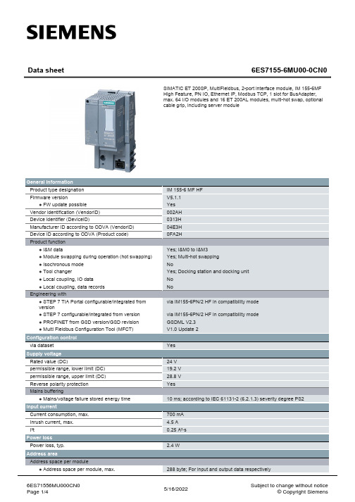
西门子ET200SP多协议接口模块数据手册说明书
PROFINET with 100 Mbit/s full duplex (100BASE-TX) No Yes; PROFINET with 100 Mbit/s full duplex (100BASE-TX) Yes Yes
Yes
16
No Yes No No
Data sheet
6ES7155-6MU00-0CN0
SIMATIC ET 200SP, MultiFieldbus, 2-port interface module, IM 155-6MF High Feature, PN IO, Ethernet IP, Modbus TCP, 1 slot for BusAdapter, max. 64 I/O modules and 16 ET 200AL modules, multi-hot swap, optional cable grip, including server module
via IM155-6PN/2 HF in compatibility mode GSDML V2.3 V1.0 Update 2
Yes
24 V 19.2 V 28.8 V Yes
10 ms; according to IEC 61131-2 (6.2.1.3) severity degree PS2
connection method / header ET-Connection ● via BU/BA Send
Mechanics/material
6ES71556MU000CN0 Page 3/4
1
Yes Yes Yes No
500 byte; (246 byte outputs / 500 byte inputs) 250 byte; (246 byte outputs / 250 byte inputs)
思普电源 三相 ASCII通讯协议
思普电源ASCII通讯协议
拟制: 2015-11-5
审核:
标准化:
批准:
更改信息登记表
1. 接口方式
RS485或RS232接口:异步,半双工,最低有效位优先发送。
默认数据格式:8-N-1(8位数据位、无校验、一位停止位),
9600 bps
2. 协议格式
ASCII 命令举例如下:
写入220.0V 电源的电压控制寄存器如下表:
3.功能解释
** “PSWAP”和“P RES”指令对相位的影响会在重新打开输出时生效。
4.通讯控制举例
说明:下文中出现的“□”代替空格
**发送5byte数据,读回8byte数据
**发送5byte数据,读回6byte数据
**读回频率为51.0HZ
**读回电压为60.0V
**读回电压为1.00A
**发送11byte数据,读回14byte数据
**设置输出电压为220.0V
**发送9byte数据,读回12byte数据
**设置输出频率为60.0HZ
**发送8byte数据,读回11byte数据
**激活485地址为2的从机,如果没有收到读回数据,则可能数据丢包,需要重发,或者没有这个地址号的485从机,这条指令只对485接口有效!。
西门子S系列PLC控制步进电机进行正反转的方法
西门子S系列PLC控制步进电机进行正反转的方法
S系列PLC是西门子公司生产的一种工业自动化控制设备,可以用于
控制和监测各种电气设备,包括步进电机。
步进电机是一种特殊的电机,
可以精确地控制位置和速度,广泛应用于工业自动化领域。
控制步进电机进行正反转可以使用以下步骤:
1.配置PLC软件:首先需要通过PLC软件配置相应的输入输出(I/O)模块。
根据实际情况,将步进电机的控制信号连接到PLC的输出模块上。
2.编写控制程序:使用PLC软件编写控制程序,控制步进电机的正反转。
PLC软件通常提供了图形化编程界面,可以通过拖拽和连接各种功能
块来搭建程序。
在程序中,可以通过设置输出信号的状态(如ON或OFF)来控制步进电机的正反转。
3.添加控制逻辑:根据步进电机的正反转逻辑,可以使用逻辑功能块
来实现控制。
比如,可以使用一个计时器来控制电机的转动时间,或者使
用一个翻转触点来实现电机的正反转切换。
4.设置步进电机的驱动器:步进电机通常需要配合驱动器使用。
驱动
器是一种电子设备,可以将PLC输出的信号转换为步进电机的工作推力。
根据具体的步进电机型号和驱动器型号,需要根据驱动器的相关规格设置
驱动工作方式,如设置电机的转动方向和步距等。
控制步进电机进行正反转的方法并不复杂,但需要确保PLC软件的配
置和编写程序的正确性。
此外,也需要根据具体的步进电机型号和驱动器
型号,了解其工作规格和特性,以便正确设置和操作。
西门子PLC扩展模块配置电源的方法
1.写入器的选择为了防止因干扰使锂电池电压变化等原因破坏RAM中的用户和程序,可选用EPROM写入器,通过它将用户程序固化在EPROM中。
现在有些西门子PLC或其编程器本身就具有EPROM写入器的功能。
2.电源模块的选择电源模块的选择较为简单,只需考虑电源的额定输出电流就可以了。
电源模块的额定电流必须大于CPU模块、I/O模块、及其它模块的总消耗电流。
电源模块选择仅对于模块式结构的西门子PLC而言,对于整体式PLC不存在电源的选择。
3.编程器的选择对于小型控制系统或不需要在线编程的西门子PLC系统,一般选用价格便宜的简易编程器。
对于由中、高档西门子PLC构成的复杂系统或需要在线编程的PLC 系统,可以选配功能强、编程方便的智能编程器,但智能编程器价格较贵。
如果有现成的个人计算机,可以选用PLC的编程软件包,在个人计算机上实现编程器的功能。
艾驰商城是国内最专业的MRO工业品网购平台,正品现货、优势价格、迅捷配送,是一站式采购的工业品商城!具有 10年工业用品电子商务领域研究,以强大的信息通道建设的优势,以及依托线下贸易交易市场在工业用品行业上游供应链的整合能力,为广大的用户提供了传感器、图尔克传感器、变频器、断路器、继电器、PLC、工控机、仪器仪表、气缸、五金工具、伺服电机、劳保用品等一系列自动化的工控产品。
如需进一步了解相PLC表产品的选型,报价,采购,参数,图片,批发等信息,请关注艾驰商城。
西门子 SIMATIC ET 200SP 数字量输出模块 DQ 8x24VDC 0.5A ST (6
SIMATICET 200SP数字量输出模块DQ 8x24VDC/0.5A ST (6ES7132-6BF01-0BA0) 设备手册Siemens AG Digital Industries Postfach 48 4890026 NÜRNBERG A5E03574579-AFⓅ 04/2019 本公司保留更改的权利Copyright © Siemens AG 2012 - 2019. 保留所有权利法律资讯警告提示系统为了您的人身安全以及避免财产损失,必须注意本手册中的提示。
人身安全的提示用一个警告三角表示,仅与财产损失有关的提示不带警告三角。
警告提示根据危险等级由高到低如下表示。
危险表示如果不采取相应的小心措施,将会导致死亡或者严重的人身伤害。
警告表示如果不采取相应的小心措施,可能导致死亡或者严重的人身伤害。
小心表示如果不采取相应的小心措施,可能导致轻微的人身伤害。
注意表示如果不采取相应的小心措施,可能导致财产损失。
当出现多个危险等级的情况下,每次总是使用最高等级的警告提示。
如果在某个警告提示中带有警告可能导致人身伤害的警告三角,则可能在该警告提示中另外还附带有可能导致财产损失的警告。
合格的专业人员本文件所属的产品/系统只允许由符合各项工作要求的合格人员进行操作。
其操作必须遵照各自附带的文件说明,特别是其中的安全及警告提示。
由于具备相关培训及经验,合格人员可以察觉本产品/系统的风险,并避免可能的危险。
按规定使用 Siemens 产品请注意下列说明:警告Siemens 产品只允许用于目录和相关技术文件中规定的使用情况。
如果要使用其他公司的产品和组件,必须得到 Siemens 推荐和允许。
正确的运输、储存、组装、装配、安装、调试、操作和维护是产品安全、正常运行的前提。
必须保证允许的环境条件。
必须注意相关文件中的提示。
商标所有带有标记符号 ® 的都是 Siemens AG 的注册商标。
西门子 KAS KAP 旁路隔离自动转换开关手册说明书
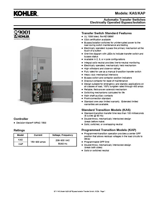
Automatic Transfer SwitchesElectrically Operated Bypass/IsolationModels:KAS/KAPControllerD Decision-Maker r MPAC1500RatingsModel Current Voltage,FrequencyKAS150-600amps 208-600VAC 50/60HzKAP Transfer Switch Standard FeaturesD UL1008listed,file#E108981D CSA certification availableD Bypass/isolation switches for uninterrupted power to the load during switch maintenance and testingD Electrically operated:bypass the primary mechanism at the touch of a buttonD One-line diagram with LEDs to indicate transfer switch and bypass statusD Available in2,3,or4pole configurationsD Integral solid neutral provides line-to-neutral monitoringD Electrically operated,mechanically held mechanismD High withstand and close-on ratingsD Fully rated for use as a manual3-position transfer switchD Heavy duty mechanical interlocksD Bypass switch and contactor position indicatorsD Drawout contactor for ease of maintenanceD Design suitable for emergency and standby applications on all classes of load,100%tungsten rated through400amps D Reliable,field-proven solenoid mechanismD Switching mechanisms lubricated for lifeD Main shaft auxiliary contactsD Front-connection standardD Standard one-year limited warranty.Extended limited warranties are available.Standard Transition Models(KAS)D Standard-transition transfer time less than100milliseconds (6cycles@60Hz)D Double-throw,mechanically interlocked design(break before make)D Solid,switched,or overlapping neutralProgrammed Transition Models(KAP)D Programmed-transition operation provides a center OFF position that allows residual voltages in the load circuits to decayD Programmable OFF timeD Double-throw,mechanically interlocked design(break both sides)D Solid or switched neutralHigh visibility alarmand operating mode indicators A simple one-line diagram indicates real-time switch and bypass statusPermitted and restricted operations indicated Single button bypass operationManual engine start controlsA single handle connects and isolates transfer switch for inspection,testing,or serviceSimple Bypass OperationAutomatic Transfer Switch ControllerThe Decision-Maker r MPAC 1500Automatic Transfer Switch Controller is used on bypass/isolation transfer switch models.Decision-Maker r MPAC 1500ControllerD LCD display,4lines x 20characters,backlitD Complete programming and viewing capability at the door using the keypad and LCD display D LED indicators:Source available,transfer switch position,service required (fault),and “not in auto”D Programmable voltage and frequency pickup and dropout settings D Programmable time delays D Programmable generator exerciser D Time-based load controlD Current-based load control (current sensing kit required)D Two programmable inputs and two programmable outputs D Up to four I/O extension modules available D Modbus communication is standard D RS-485communication standard D Ethernet communication standard D Three-source system D Prime powerFor more information about Decision-Maker r MPAC 1500features and functions,see specification sheet G11-128.Codes and StandardsThe ATS meets or exceeds the requirements of the following specifications:D CSA C22.2No.178certification available,file #LR58301D EN61000-4-4Fast Transient Immunity Severity Level 4D EN61000-4-5Surge Immunity Class 4(voltage sensing and programmable inputs only)D IEC Specifications for EMI/EMC Immunity:d CISPR 11,Radiated Emissions d IEC 1000-4-2,Electrostatic Discharged IEC 1000-4-3,Radiated Electromagnetic Fields d IEC 1000-4-4,Electrical Fast Transients (Bursts)d IEC 1000-4-5,Surge Voltaged IEC 1000-4-6,Conducted RF Disturbances d IEC 1000-4-8,Magnetic Fieldsd IEC 1000-4-11,Voltage Dips and Interruptions D IEEE Standard 446,IEEE Recommended Practice for Emergency and Standby Power Systems for Commercial and Industrial Applications D IEEE 472(ANSI C37.90A)Ring Wave TestD NEMA Standard ICS 10-2005,Electromechanical AC Transfer Switch Equipment D NFPA 70,National Electrical CodeD NFPA 99,Essential Electrical Systems for Health Care Facilities D NFPA 110,Emergency and Standby Power Systems D Underwriters Laboratories UL 508,Standard for Industrial Control Equipment D Underwriters Laboratories UL 1008,Standard for Automatic Transfer Switches for Use in Emergency Standby Systems,file #E108981Application DataEnvironmental Specifications Operating T emperature-20q C to70q C(-4q F to158q F) Storage Temperature-40q C to85q C(-40q F to185q F) Humidity5%to95%noncondensingAuxiliary Position Indicating Contacts(rated10amps@32VDC/250VAC)Switch Rating,Amps Number of Contacts Indicating Normal,EmergencyKAS KAP150-6008,87,7Input and Output Connection Specifications Component Wire Size RangeMain board I/O terminals#12-24AWGI/O module terminals#14-24AWGCable SizesUL-Listed Solderless Screw-Type Terminalsfor External Power ConnectionsSwitchRating,AmpsRange of Wire Sizes,Copper or Aluminum*Normal,Emergency,and LoadTerminals Per Phase and Neutral Ground150-400(1)#4AWG to600KCMIL or(2)1/0AWG to250KCMIL(3)600KCMIL 600(2)#2AWG to600KCMIL(6)600KCMIL *Use75_C minimum Cu/Al wire for power connections.Weights and DimensionsNote:Weights and dimensions are provided for reference only.Always use the transfer switch dimension drawing for planning and installation.Weights and dimensions may vary for different configurations.See your local distributor for dimension drawings.Weights and dimensions are shown for bypass/isolation transfer switches in NEMA type1enclosures.See the transfer switch dimension drawings for other enclosure types.Model AmpsDimensions mm(in.)Weight kg(lb.)*DimensionDrawing Height Width Depth2-Pole3-Pole4-PoleKAS KAP 150-2602162(85.1)864(34)711(28)**431(950)431(950)431(950)ADV-9230 150-600w/12”pull box[2162(85.1)1168(46)711(28)**431(950)431(950)431(950)150-600w/15”pull box[2162(85.1)1245(49)711(28)**431(950)431(950)431(950)*Approximate weights[Pull box is required for bottom cable entry on400-600amp units;optional on150-260amp units.**Transfer switch carriage manual crank handle can be removed.Also note that the transfer switch carriage manual crank handle can be left in place and folded down.Recommended front clearance is32in.minimum.Withstand and Close-On Ratings(WCR)Maximum current in RMS symmetrical amperes when coordinated with customer-supplied fuses or circuit breakers.All values are available symmetrical RMS amperes and tested in accordance with the withstand and close-on requirements of UL1008.Application requirements may permit higher withstand ratings for certain size switches.Contact the factory for assistance.Note:For specific breaker ratings,refer to the next table.Switch Rating, AmpsWithstand Current Ratings in RMS Symmetrical Amperes Short Time Ratings(sec.)]Current-Limiting Fuses Time-Based Rating*480V Max.600V Max. Amps@480VAmps@600VAmps,Max.FuseClassAmps@240VAmps@480VAmps@600V.13.2.3.5.1.13.3.5150225 260 400 600200kA200kA600J65kA42kA[35kA7500A——800L*Based on0.050seconds(approximately3cycles).Applicable to breakers with instantaneous trip elements.[Applicable to2-pole,3-pole,and conventional4-pole switches only.Overlapping neutral switches have“any”breaker ratings of35kA, 0.050seconds at480V.]Short time ratings are provided for applications involving breakers that utilize trip delay settings for system selective coordination.Ratings with Specific Manufacturers’Circuit BreakersThe following charts list power switching device withstand and close-on ratings(WCR)in RMS symmetrical amperes for circuit breakers from specific manufacturers.Ratings apply to both open-and programmed-transition models.Circuit breakers are supplied by the customer.Switch Rating, ampsMolded-Case Circuit BreakersWCR,amps RMSVoltage,Max.Manufacturer TypeMax.Size,amps150 22565,000240GETHQMV225SGL1,SGL4,SGL6,SGP1,SGP4,SGP6600 Eaton/Cutler Hammer LDC,CLDC,HLD,CHLD600Siemens/ITE HLD6,HLXD6600Square D QG,QJ250 100,000Square DLJ(current limiting)600 125,000LL(current limiting)600200,000LR(current limiting)600 Eaton/Cutler HammerPD2(current limiting)225PD3(current limiting)60050,000480Eaton/Cutler HammerHFDE,FDC,FDCE225NHH250JDC,JGU,JGX350HKD,CHKD,KDC,HKDB,CHKDB,LHH400HLD,CHLD,LDC,CLDC,LGH*,LGC*,LGU*,LGX*600HMDLB,CHMDLB800 GESEL,SEP150SFL,SFP,FEN,FEH250TBC4400FGN,FGH,FGL,FGP,SGL1,SGL4,SGL6,SGP1,SGP4,SGP6.TJL4V,TJL1S-6S,TBC6600TB8800 Siemens/ITEHDG,LDG150HFD,HFD6,HFXD,HFXD6,HHFD6,HHFXD6,CFD6,HFG,LFG250HJD,HJD6,HJXD,HJXD6,SHJD,SHJD6,HHJD6,HHJXD6,CJD6,SCJD6,HJG,LJG,LLG400HLD6,HLXD6,HHLD6,HHLXD6,CLD6,SHLD6,SCLD6,HLG600 Square DHJ,HL150KC,KI,CF250L,NSF250250CK400N,CK400NN,CK400H,CK400HH,CJ400L,NSJ400400LC,DJ,DL,LI,NSJ600600MasterPact STR28D,PK,PJ,PL800 65,000JJ(current limiting)250LJ(current limiting)600 100,000JL(current limiting)250LL(current limiting)600 Eaton/Cutler HammerPD2(current limiting)225PD3(current limiting)600 200,000Square DJR(current limiting)250LR(current limiting)60042,000600Eaton/Cutler HammerJGU,JGX,JGH250KDC400LDC,CLDC600 GETBC4400SGL1,SGL4,SGL6,SGP1,SGP4,SGP6,FGP600 Siemens/ITEHJD,CFD6250HHJD6,HHJXD6,CJD6,SCJD6400HHLD6,HHLXD6,CLD6,SCLD6,LNG,LPG,LGC*,LGU*,LGX*600 Square DHJ,HL,HG150KI,JJ,JL,JR,CF250L250CK400H,CK400HH,CJ400L400LI,MasterPact STR28D,PK600 50,000LL(current limiting)60065,000Eaton/Cutler Hammer PD3(current limiting)600 100,000Square D LR(current limiting)600*With Digitrip310+LS or LSG Inst.Override set to12X.Switch Molded-Case Circuit BreakersRating, ampsMax.Size,ampsTypeManufacturerVoltage,Max.WCR,amps RMS260 26065,000240GETHQMV225SGL1,SGL4,SGL6,SGP1,SGP4,SGP6600 Eaton/Cutler Hammer LDC,CLDC,HLD,CHLD600 65,000Siemens/ITE HLD6,HLXD6600Square DQG,QJ250 100,000LJ(current limiting)600 125,000LL(current limiting)600200,000LR(current limiting)600 Eaton/Cutler HammerPD2(current limiting)225PD3(current limiting)60050,000480Eaton/Cutler HammerHFDE,FDCE,HFD,FDC,LHH225JDC,JGH,JGC,JGU,JGX250HKD,HKDB,CHKD,CHKDB,KDC400HLD,CHLD,LDC,CLDC,LGH*,LGC*,LGU*,LGX*,NHH600MDL,CMDL,HMDL,CHMDL,NGS,NGH,NGC,MDLB,CMDLB,HMDLB,CHMDLB800 GESFL,SFP,FEN,FEH250TBC4400TBC6,TJL4V,TJL1S-6S,SGL1,SGL4,SGL6,SGP1,SGP4,SGP6,FGN,FGH,FGL,FGP600TBC8,TKL4V,TKH8S-12S,TKL8S-12S,SKH8,SKL8,SKP8,TB8800 Siemens/ITEHFD6,HFXD6,HHFD6,HHFXD6,CFD6,HFG,LFG250HJD6,HJXD6,SHJD6,HHJD6,HHJXD6,CJD6,SCJD6,HJG,LJG,LLG400HLD6,HLXD6,SHLD6,HHLD6,HHLXD6,CLD6,SCLD6,HLG600LMD,LMD6,LMXD,LMXD6,HLMD,HLMD6,HLMXD,HLMXD6,MD,MD6,MXD6,HMG,HMD6,HMXD6,SMD6,SHMD6,CMD6,SCMD6,LMG,MG800 Square DKI,KC,CF250L,NSF250250CK400N,CK400NN,CK400H,CK400HH,CJ400L,NSJ400400LC,DJ,DL,LJ,LL,LR,LI,NSJ600600CK800N,CK800NN,CK800H,CK800HH,MasterPact STR28D,MJ,PK,PJ,PL800CK1000HL1000CK1200NN,CK1200HH1200 65,000JJ(current limiting)250LJ(current limiting)600 100,000JL(current limiting)250LL(current limiting)600 200,000JR(current limiting)250LR(current limiting)600 Eaton/Cutler HammerPD2(current limiting)225PD3(current limiting)60042,000600Eaton/Cutler HammerJGU,JGX250KDC400LDC,CLDC600 GETBC4400TBC6,SGL1,SGL4,SGL6,SGP1,SGP4,SGP6,FGP600TBC8,TKL4V,TKL8S-12S,SKL8,SKP8800 Siemens/ITEHJD,CFD6250HHJD6,HHJXD6,CJD6,SCJD6400HHLD6,HHLXD6,CLD6,SCLD6600HLMD6,HLMXD6,HMXD6,SHMD6,HMD6,CMD6,SCMD6,LMG,LNG,LPG,LGC*,LGU*,LGX*800 Square DKI,JL,JR,JJ,CF250L250CK400H,CK400HH,CJ400L400LI600CK800H,CK800HH,MasterPact STR28D,PK800 50,000LL(current limiting)60065,000Eaton/Cutler Hammer PD3(current limiting)600 100,000Square D LR(current limiting)600*With Digitrip310+LS or LSG Inst.Override set to12X.Switch Molded-Case Circuit BreakersRating, ampsMax.Size,ampsTypeManufacturerVoltage,Max.WCR,amps RMS40065,000240GETHQMV225SGL1,SGL4,SGL6,SGP1,SGP4,SGP6600Eaton/Cutler HammerLDC,CLDC,HLD,CHLD600 200,000PD2(current limiting)225PD3(current limiting)600 65,000Siemens/ITE HLD6,HLXD6600Square DQG,QJ250 100,000LJ(current limiting)600 125,000LL(current limiting)600 200,000LR(current limiting)60050,000480Eaton/Cutler HammerJGH,JGC,NHH250HKD,CHKD,KDC,HKDB,CHKDB,LHH400CHLD,LDC,CLDC,LGH*,LGC*,LGU*,LGX*600MDL,CMDL,HMDL,CHMDL,NGS,NGH,NGC,MDLB,CMDLB,HMDLB,CHMDLB800NGU1600 GETBC4400TBC6,TJL4V,TJL1S-6S,SGL1,SGL4,SGL6,SGP1,SGP4,SGP6,FGN,FGH,FGL,FGP600TBC8,TKL4V,TKH8S-12S,TKL8S-12S,SKH8,SKL8,SKP8,TB8800 Siemens/ITEHFD6,HFXD6,HFG,LFG250HJD6,HJXD6,SHJD6,HHJD6,HHJXD6,CJD6,SCJD6,HJG,LLG,LJG400HLD6,HLXD6,SHLD6,HHLD6,HHLXD6,CLD6,SCLD6,HLG600LMD6,LMXD6,HLMD6,HLMXD6,MD6,MXD6,HMD6,HMXD6,SMD6,SHMD6,CMD6,SCMD6,HMG,LMG800 Square DCK400N,CK400NN,CK400H,CK400HH,CJ400L,NSJ400400LC,DJ,DL,LJ,LL,LR,LI,NSJ600600CK800N,CK800NN,CK800H,CK800HH,MJ800CK1000HH1000PK,PJ,PL,MH,MasterPact STR28D,CK1200HH1200 65,000LJ(current limiting)600 100,000LL(current limiting)600 200,000LR(current limiting)600100,000Eaton/Cutler Hammer PD3(current limiting)600 42,000600Eaton/Cutler HammerKDC400LDC,CLDC,LGC*,LGU*,LGX*600 65,000PD3(current limiting)60042,000GETBC4400TBC6,SGL1,SGL4,SGL6,SGP1,SGP4,SGP6,FGP600TBC8,TKL4V,TKL8S-12S,SKL8,SKP8800 Siemens/ITEHHJD6,HHJXD6,CJD6,SCJD6400HHLD6,HHLXD6,CLD6,SCLD6600HLMD6,HLMXD6,HMXD6,SHMD6,HMD6,CMD6,SCMD6,LMG800LNG,LPG1200 Square DCK400H,CK400HH,CJ400L400LI600CK800H,CK800HH800MasterPact STR28D,PK1200 50,000LL(current limiting)600 100,000LR(current limiting)600*With Digitrip310+LS or LSG Inst.Override set to12X.Switch Molded-Case Circuit BreakersRating, ampsMax.Size,ampsTypeManufacturerVoltage,Max.WCR,amps RMS60065,000240GETHQMV225SGL1,SGL4,SGL6,SGP1,SGP4,SGP6600 Siemens/ITE HLD6,HLXD6600Eaton/Cutler Hammer LDC,CLDC,HLD,CHLD600Square DQG,QJ250 100,000LJ(current limiting)600 125,000LL(current limiting)600200,000LR(current limiting)600 Eaton/Cutler HammerPD2(current limiting)225PD3(current limiting)60050,000480Eaton/Cutler HammerJGH,JGC,HFG,LFG250HLD,CHLD,LDC,CLDC,LGH*,LGC*,LGU*,LGX*600MDL,CMDL,HMDL,CHMDL,NGS,NGH,NGC,NGU,MDLB,CMDLB,NF800 GETBC6,TJL4V,TJL1S-6S,SGL1,SGL4,SGL6,SGP1,SGP4,SGP6,FGN,FGH,FGL,FGP600TBC8,TKL4V,TKH8S-12S,TKL8S-12S,SKH8,SKL8,SKP8,TB8800SKL12,SK12P1200 Siemens/ITEHLD6,HLXD6,SHLD6,HHLD6,HHLXD6,CLD6,SCLD6,HLG,LLG600LMD6,LMXD6,HLMD6,HLMXD6,MD6,MXD6,HMD6,HMXD6,SMD6,SHMD6,CMD6,SCMD6,HMG,LMG800HND6,HNXD6,SND6,SHND6,ND6,NXD6,HNG,LNG,CND61200 Square DLC,DJ,DL,LI,NSJ600600CK800N,CK800NN,MJ800MH,CK1200N,CK1200NN,CK1200H,CK1200HH,NT-H,NT-L1,NT-L,NT-LF,PK,PJ,PL1200CM2000HH2000CM2500HH2500 85,000PL12001200 65,000LJ(current limiting)600 100,000LL(current limiting)600 200,000LR(current limiting)600100,000Eaton/Cutler Hammer PD3(current limiting)60042,000600Eaton/Cutler HammerJGC250TBC4400LDC,CLDC600 GETBC6,SGL1,SGL4,SGL6,SGP1,SGP4,SGP6,FGP600TBC8,TKL4V,TKL8S-12S,SKL8,SKP8800SKL12,SKP121200 Siemens/ITEHHLD6,HHLXD6,CLD6,SCLD6600HLMD6,HLMXD6,HMXD6,SHMD6,HMD6,CMD6,SCMD6,LMG800HND6,HNXD6,HNG,LNG,SHND61200 Square DLI600CK800H,CK800HH800CK1000HL1000CK1200H,CK1200HH,NT-H,NT-L,NT-LF,NT-L1,MasterPact STR28D,PK1200 50,000LL(current limiting)60065,000Eaton/Cutler Hammer PD3(current limiting)600 100,000Square D LR(current limiting)600*With Digitrip310+LS or LSG Inst.Override set to12X.Controller AccessoriesSee the controller specification sheet for more information. -Accessory ModulesD Alarm ModuleD External Battery Supply ModuleD Input/Output ModuleD High-Power Input/Output Module-Controller Disconnect Switch-Current Sensing Kit-Padlockable User Interface Cover-Supervised Transfer Control SwitchTransfer Switch Accessories Accessories are available either factory-installed or as loose kits,unless otherwise noted.-CSA Certification-Digital MeterD Measure and display voltage,current,frequency,andpowerD35programmable alarmsD LCD display,67x62.5mm(2.65x2.5in.)D Pushbutton operationD Password-protected programming menusD Two digital inputsD Two digital outputsD Two Form A relay outputsD Serial port for optional network connectionsD Data loggingD Factory-installed-Engine Start Circuit MonitorSee Specification Sheet G6-165.-Export Packaging-Extended Limited WarrantiesD2-year basicD5-year basicD5-year comprehensiveD10-year major components-Heater,Anti-CondensationD Hygrostat-controlled120VAC strip heater(customer-supplied voltage source required)D100or250watts(sized for enclosure)D Protective15Amp circuit breaker -Literature KitsD Production literature kit(one kit is included with each transfer switch)D Overhaul literature kit-Load Shed KitD Forced transfer from Emergency to OFF forprogrammed-transition modelsD Customer-supplied signal(contact closure)is required forthe forced transfer to OFF functionD Factory-installed only-Pull BoxesD Required for bottom cable entry on400-600amp unitsD Optional for150-260amp unitsD Available in305and381mm(12and15inch)widths-RSA III Remote Serial AnnunciatorD Monitors the generator setD Monitors Normal and Emergency source status andconnectionD Monitors ATS common alarmD Allows remote testing of the ATSD For more information,see specification sheet G6-139.-Surge Protection Device(SPD)D SPD available for the normal source supplyD Surge protection reduces transient voltages to harmlesslevelsD Protection modes:L-L/L-N/L-G/N-GD Replaceable phase and neutral cartridges for serviceD Frequency:50-60HzD Operating Temperature Range:-40to176_F(-40to80_C)D Remote contacts for customer-supplied status indicators:Contacts:1NO,1NCMin Load:12VDC/10mAMax.Load:250VAC/1AWire Size(max.):16AWGD Fuse protection:30amps/600VD UL1449,3rd Edition for Type2applicationsD IEC61-643-1,2nd Edition T2/11D See additional SPD specifications belowSPD SpecificationsNominal Voltage (V15%)Max.DischargeCurrent(kA)Phase PolesUL VPR3rd Ed(L-N/N-G/L-G)(kV)Limiting Voltage,(L-N/N-G/L-G)(kV)Short CircuitWithstandCurrent(kA)MaximumContinuousOperatingVoltage(VAC)at3kAmps at10kAmp240/12040Split30.6/1.2/0.70.6/0.4/0.60.8/0.7/0.8200175/350 208/12040Wye40.6/1.2/0.70.6/0.4/0.60.8/0.7/0.8200175/350 480/27740Wye4 1.0/1.2/1.1 1.0/0.4/1.0 1.2/0.7/1.2200320/640 240/12040HLD4 1.0/1.2/1.1 1.0/0.4/1.0 1.2/0.7/1.2200320/640 600/34740Wye4 1.3/1.2/1.4 1.3/0.4/1.3 1.5/0.7/1.5200440/880Availability is subject to change without notice.Kohler Co.reserves the right to change the design or specifications without notice and without any obligation or liability whatsoever.Contact your local Kohler r Power Systems distributor for availability.DISTRIBUTED BY:¤2021Kohler Co.All rights reserved.Model DesignationRecord the transfer switch model designation in the boxes.The transfer switch model designation defines characteristics and ratings as explained below.Sample Model Designation:KAS-DMVA-0400SKOHLER CO.,Kohler,Wisconsin 53044USA Phone 920-457-4441,Fax 920-459-1646For the nearest sales and service outlet in the US and Canada,phone Model K:KohlerMechanism A:Electrically Operated Bypass/IsolationTransition S:Standard P:ProgrammedController D:Decision-Maker r MPAC 1500,AutomaticVoltage/Frequency C:208Volts /60Hz K:440Volts/60Hz D:220Volts /50Hz M:480Volts/60Hz F:240Volts/60Hz N:600Volts/60Hz G:380Volts /50Hz P:380Volts/60Hz H:400Volts /50Hz R:220Volts/60Hz J:416Volts /50HzS:400Volts/60HzNumber of Poles/Wires N:2Poles /3Wires,Solid Neutral T :3Poles /4Wires,Solid Neutral V:4Poles/4Wires,Switched NeutralW:4Poles /4Wires,Overlapping Neutral (KAS only)Enclosure A:NEMA 1C:NEMA 3RCurrent,Amps01500225026004000600Connections S:Standard Note:Some selections are not available on all models.Contactyour Kohler distributor for availability.。
实现西门子,欧姆龙、三菱,AB等PLC之间数据交换的协议转换方案
1 需求背景工控项目中经常遇到西门子、三菱、欧姆龙、AB 等不同的PLC ,有时候需要实现这些PLC 之间的信息交换。
但是这些PLC 之间的通信协议并不兼容,不能实现两个品牌的PLC 之间的直接通信。
在此需求下,使用协议转换网关,可轻松实现不同plc 之间的数据交换,并且不需要更改plc 里的程序。
2 工作原理如下图所示,网关设备作为一个桥梁连接在西门子PLC 和AB PLC 之间。
工作原理是网关分别和两种PLC进行通信。
用户可以在onker 网关里进行配置,建立两个PLC 设备之间的数据对应关系。
数据变化后,则网关会自动把变化的数据发送给对应的PLC 中。
同样,通过网关也可以实现其他品牌的PLC 之间的数据交换。
3 设备连接网关和西门子,三菱、欧姆龙、AB PLC 进行网线连接,这些设备可以在同一个网段,也可以在不同的网段。
4 使用方法1. 下面以西门子PLC 和AB PLC 为例说明如何把一个PLC 里的数据传递给另外一个PLC 。
2. 首先在网关中添加一个采集设备,采集AB PLC 的数据。
西门子PLC 总线AB PLC总线网关3.4.添加采集PLC中B3:0/0(标签AB1),B3:0/1(标签AB2)的数据标签。
读写控制为“读”。
5.6.再新建一个采集设备,采集西门子PLC的数据7.8.建好设备后,新增两个Q0.0和Q0.1的数据标签。
读写控制为“读写”。
9.10.此时需要把AB PLC中的B3:0/0,B3:0/1的值写到西门子1200的Q0.0和Q0.1寄存器中。
11.点击SE(1),再双击SE1(2),在弹出的窗口中点击(3),12.13.点击下图(4),在弹出的对话框中选择对应的变量。
14.15.设置完成后,如下图所示。
16.17.配置完成后,下载的网关中运行,连接好AB,西门子PLC,就可以实现AB PLC中B3:0/0,B3:0/1的值写到西门子1200的Q0.0和Q0.1寄存器中。
西门子SIMATIC系列直接开关电源电机启动器3RK1308-0AE00-0CP0的数据手册说明书

Main circuit Number of poles for main current circuit Design of the switching contact Adjustable pick-up value current of the currentdependent overload release Minimum load [%] Type of the motor protection Operating voltage ● rated value Relative symmetrical tolerance of the operating voltage Operating frequency 1 rated value Operating frequency 2 rated value Relative symmetrical tolerance of the operating frequency Relative positive tolerance of the operating frequency Relative negative tolerance of the operating frequency Operating current ● at AC at 400 V rated value Ampacity when starting maximum Operating power for three-phase motors at 400 V at 50 Hz
3 Hybrid 4 ... 12 A
50 %; from smallest adjustable rated current solid-state
48 ... 500 V 10 %
50 Hz 2.2 ... 5.5 kW
西门子电子有限公司电力传输与分发控制器升级说明书
SCustomer Service Department Power Transmission Division***********************MJXtra 2.0 Firmware Upgrage Program********************* Date: March 1, 2003From: Robert ChampionSubject: Firmware Upgrade Notes for Siemens MJX and MJXL Regulator Controls================================================================**************************MJX CONTROLS*******************************1. For some older controls, first identify the PROM.Go to the “Configure” Menu, go down the menu to the “Version” line item. The possible entries would be 1.9 through 2.52. If the entry is 2.41 or higher, the control has anEEProm inside that can be programmed through the front panel data port using the MJXtra Program.NOTE: If the version is 1.9 through 2.30, the control has a UVProm inside and CANNOT be programmed through the front data port. If the prom is replaced with a EEProm, then the unit CAN be reprogrammed through the front data port. The prom is socketed and can be replaced with a EEprom purchased from the factory.Using the MJXtra 2.0 program on the CD, you are able to upgrade Version 2.41 or higher to the latest version. The upload process will take 12 to 15 minutes per control panel.THE CONTROL OR THE COMPUTER MUST NOT POWER DOWN DURING THE UPLOAD PROCESS.*****The latest released version for the MJX Control is 2.52.*****=================================================================**************************MJXL CONTROLS******************************* 1. First identify the “BOOT” version.With the control powered down, turn the control power on and note the Boot Versionnumber that appears on the display. The possible numbers would be 1.0001, 1.0002,1.0003, or 1.0004. If 1.0003 or 1.0004 appears, the control CAN be reprogrammedthrough the front data port using the MJXtra program. If 1.0001 appears it CANNOTbe reprogrammed through the front data port. If the 1.0002 number appears, it may ormay not be done. This is where, what is referred as the “A” chip, may be. If you choose to verify the chip (“A” Chip, or NOT an “A” Chip), refer to the pictures on the Hand-Out CD, or the attached copies of the pictures. DO NOT ATTEMPT AN UPGRADE WITH THE “A” CHIPNOTE: The chip is not easily replaceable because it is not socketed. For now, ifreprogramming is desired, it is recommended that the control be returned to the factoryfor reprogramming. In the near future, the upgrading program for the earlier BootVersions should be available for field upgrading.page 1 of 2Siemens Power Transmission & Distribution Inc. P.O. Box 6289, Jackson, MS 39288-6289444 Highway 49 South, Richland, MS 39218 Tel. 601 936-9153 Cell 601 940 7161 Fax 601 936 9151*********************************SNext, go to the “Configure” menu and note the “Version” number (3.02, 3.0211 or 3.04).If the version is 3.02 or 3.0211, using the MJXtra 2.0 program, first install 3.04. This will take approximately 12 to 15 minutes. After 3.04 is installed, then repeat the process and install 3.06. This will also take 12 to 15 minutes. Once the installation is complete, the control will automatically reboot and display “METER”. Using the power switch, turn the control off and then back on and verify/set the “Configure” menu line items.THE CONTROL OR THE COMPUTER MUST NOT POWER DOWN DURING THE UPLOAD PROCESS***** The latest released version for the MJXL Control is 3.06.*****================================================================= The latest firmware releases for the MJX and the MJXL Controls will add a few additional line items in the “Configure” menus of each control. Attached is a list of the complete menu listings after an upgrade has been completed.The additional programming in these New Firmware versions (MJX 2.52, and MJXL 3.06) are for enhancements to the “Tap Tracking” issues of the past, as well as other enhancements. The additions are not listed in the Control Panel ManualThe complete “Configure” menu line items will be discussed during this training class.The Engineering Release Notes for the MJX 2.52 and MJXL 3.06 are attached.================================================================= To load the MJXtra 2.0 program to your computer from the CD:1.Left click on the “MJXtra” heading of the front page.2.On the left hand side of the page, Left Click on “MJXtra Install”3.The program will autoload. (Entering company name will be required)**Moving the following firmware versions to the MJXtra Program from the CD may benecessary, IF, they are not already present. To do this:1. Return to “My Computer”, Right Click on “CD Drive”, Left Click on “Open”2. Identify the following folder: “’D’ Files-Firmware Versions”, Left Click on the Folder.3. Save the following Firmware versions to “My Documents”:MP 2.52.s19 (MJX)MP 3.04.s19 (MJXL)MP 3.06.s19 (MJXL)3. Next, move each of the .s19 files from “My Documents” to the MJXtra 2.0 program that you have loaded into the program files of your computer. (i.e. “Drag and Drop, Cut and Paste, etc.)The MJXtra 2.0 Program will then be ready to use.****Refer to File #A9 Folder (Communication Settings) on the Front Page, for communicating to the controls with MJXtra and MJXplorer.Page 2 of 2 Siemens Power Transmission & Distribution Inc.。
西门子指令一览表
1 位逻辑指令1、1 -||- 常开接点(地址)1、2 -|/|- 常闭接点(地址)1、3 XOR 位异或1、4 -|NOT|- 信号流反向1、5 -( ) 输出线圈1、6 -(#)- 中间输出1、7 -(R) 线圈复位1、8 -(S) 线圈置位1、9 RS 复位置位触发器1、10 RS 置位复位触发器1、11 -(N)- RLO下降沿检测1、12 -(P)- PLO上升沿检测1、13 -(SAVE) 将RLO存入BR存储器1、14 MEG 地址下降沿检测1、15 POS 地址上升沿检测2 比较指令2、1 CMP?I 整数比较2、2 CMP?D 双整数比较2、3 CMP?R 实数比较3 转换指令3、1 BCD_IBCD码转换为整数3、2 I_BCD 整数转换为BCD码3、3 I_DINT 整数转换为双整数3、4 BCD_DIBCD码转换为双整数3、5 DI_BCD 双整数转换为BCD码3、6 DI_REAL 双整数转换为浮点数3、7 INV_I 整数得二进制反码3、8 INV_DI 双整数得二进制反码3、9 NEG_I 整数得二进制补码3、10 NEG_DI 双整数得二进制补码3、11 NEG_R 浮点数求反3、12 ROUND 舍入为双整数3、13 TRUNC 舍去小数取整为双整数3、14 CEIL 上取整3、15 FLOOR 下取整4 计数器指令4、1 S_CUD 加减计数4、2 S_CU 加计数器4、3 S_CD 减计数器4、4 -(SC) 计数器置初值4、5 -(CU) 加计数器线圈4、6 -(CD) 减计数器线圈5 数据块指令5、1 -(OPN) 打开数据块:DB或DI6 逻辑控制指令6、1 -(JMP) 无条件跳转6、2 -(JMP) 条件跳转6、3 -(JMPN) 若非则跳转6、4 LABEL 标号7 整数算术运算指令7、1 ADD_I 整数加法7、2 SUB_I 整数减法7、3 MUL_I 整数乘法7、4 DIV_I 整数除法7、5 ADD_DI 双整数加法7、6 SUB_DI 双整数减法7、7 MUL_DI 双整数乘法7、8 DIV_DI 双整数除法7、9 MOD_DI 回送余数得双整数8 浮点算术运算指令8、1 基础指令8、1、1 ADD_R 实数加法8、1、2 SUB_R 实数减法8、1、3 MUL_R 实数乘法8、1、4 DIV_R 实数除法8、1、5 ABS 浮点数绝对值运算8、2 扩展指令8、2、1 SQR 浮点数平方8、2、2 SQRT 浮点数平方根8、2、3 EXP 浮点数指数运算8、2、4 LN 浮点数自然对数运算8、2、5 SIN 浮点数正弦运算8、4、6 COS 浮点数余弦运算8、2、7 TAN 浮点数正切运算8、2、8 ASIN 浮点数反正弦运算8、2、9 ACOS 浮点数反余弦运算8、2、10ATAN 浮点数反正切运算9 赋值指令9、1 MOVE 赋值10 程序控制指令10、1 -(Call) 从线圈调用FC/SFC(无参数) 10、2 CALL_FB 从方块调用FB10、3 CALL_FC 从方块调用FC10、4 CALL_SFB 从方块调用SFB10、5 CALL_SFC 从方块调用SFC10、7 -(MCR>) 主控继电器断开10、8 -(MCRA) 主控继电器启动10、9 -(MCRD) 主控继电器停止10、10 -(RET) 返回11 移位与循环指令11、1 移位指令11、1、1 SHR_I 整数右移11、1、2 SHR_DI 双整数右移11、1、3 SHL_W 字左移11、1、4 SHR_W 字右移11、1、5 SHL_DW 双字左移11、1、6 SHR_DW 双字右移11、2 循环指令11、2、1 ROL_DW 双字左循环11、2、2 ROR_DW 双字右循环12 状态位指令12、1 OV -||- 溢出异常位12、2 OS -||- 存储溢出异常位12、3 UO -||- 无序异常位12、4 BR -||- 异常位二进制结果12、5 ==0-||- 结果位等于"0"12、6 <>0-||- 结果位不等于"0"12、7 >0-||- 结果位大于"0"12、8 <0-||- 结果位小于"0"12、9 >=0-||- 结果位大于等于"0"12、10 <=0-||- 结果位小于等于"0"13 定时器指令13、1 S_PULSE 脉冲S5定时器13、2 S_PEXT 扩展脉冲S5定时器13、3 S_ODT 接通延时S5定时器13、4 S_ODTS 保持型接通延时S5定时器13、5 S_OFFDT 断电延时S5定时器13、6 -(SP) 脉冲定时器线圈13、7 -(SE) 扩展脉冲定时器线圈13、8 -(SD) 接通延时定时器线圈13、9 -(SS) 保持型接通延时定时器线圈13、10 -(SF) 断开延时定时器线圈14 字逻辑指令14、1 WAND_W 字与字相"与"14、2 WOR_W 字与字相"或"14、3 WAND_DW 双字与双字相"与"14、4 WOR_DW 双字与双字相"或"14、5 WXOR_W 字与字相"异或"14、6 WXOR_DW 双字与双字相"异或。
西门子PLC转换指令

西门⼦PLC转换指令
西门⼦PLC转换指令
转换指令是指对操作数的类型进⾏转换,包括数据的类型转换、码的类型
转换以及数据和码之间的类型转换。
⼀、数据类型转换(⼀)字节与整数
1、字节到整数
BTI,字节转换为整数指令。
使能输⼊有效时,将字节输⼊数据IN 转换成整
数类型,并将结果送到OUT 输出。
字节型是⽆符号的,所以没有符号扩展。
使能流输出ENO 断开的出错条件:SM4.3 (运⾏时间);0006 (间接寻址)。
指令格式:BTI IN, OUT
例:BTI VB0, AC0
2、整数到字节
ITB,整数转换字节指令。
使能输⼊有效时,将整数输⼊数据IN 转换成字节
类型,并将结果送到OUT 输出。
输⼊数据超出字节范围(0~255)则产⽣溢出。
移位指令影响的特殊存储器位:SM1.1(溢出)。
使能流输出ENO 断开的出错
条件:SM1.1(溢出);SM4.3(运⾏时间);0006(间接寻址)。
指令格式:ITB IN, OUT
例:ITB AC0, VB10
(⼆)整数与双整数
1、双整数到整数
DTI,双整数转换为整数指令。
使能输⼊有效时,将双整数输⼊数据IN 转换
成整数类型,并将结果送到OUT 输出。
输⼊数据超出整数范围则产⽣溢出。
移位指令影响的特殊存储器位:SM1.1(溢出)。
使能流输出ENO 断开的出错。
西门子指令一览表

1 位逻辑指令-||- 常开接点地址-|/|- 常闭接点地址XOR 位异或-|NOT|- 信号流反向- 输出线圈-- 中间输出-R 线圈复位-S 线圈置位RS 复位置位触发器RS 置位复位触发器-N- RLO下降沿检测-P- PLO上升沿检测-SAVE 将RLO存入BR存储器 MEG 地址下降沿检测POS 地址上升沿检测2 比较指令CMP I 整数比较CMP D 双整数比较CMP R 实数比较3 转换指令BCD_IBCD码转换为整数I_BCD 整数转换为BCD码I_DINT 整数转换为双整数BCD_DIBCD码转换为双整数DI_BCD 双整数转换为BCD码 DI_REAL 双整数转换为浮点数 INV_I 整数的二进制反码INV_DI 双整数的二进制反码 NEG_I 整数的二进制补码NEG_DI 双整数的二进制补码 NEG_R 浮点数求反ROUND 舍入为双整数TRUNC 舍去小数取整为双整数 CEIL 上取整FLOOR 下取整4 计数器指令S_CUD 加减计数S_CU 加计数器S_CD 减计数器-SC 计数器置初值-CU 加计数器线圈-CD 减计数器线圈5 数据块指令-OPN 打开数据块:DB或DI 6 逻辑控制指令-JMP 无条件跳转-JMP 条件跳转-JMPN 若非则跳转LABEL 标号7 整数算术运算指令ADD_I 整数加法SUB_I 整数减法MUL_I 整数乘法DIV_I 整数除法ADD_DI 双整数加法SUB_DI 双整数减法MUL_DI 双整数乘法DIV_DI 双整数除法MOD_DI 回送余数的双整数8 浮点算术运算指令基础指令8.1.1 ADD_R 实数加法SUB_R 实数减法MUL_R 实数乘法DIV_R 实数除法ABS 浮点数绝对值运算扩展指令SQR 浮点数平方SQRT 浮点数平方根EXP 浮点数指数运算LN 浮点数自然对数运算SIN 浮点数正弦运算COS 浮点数余弦运算TAN 浮点数正切运算ASIN 浮点数反正弦运算ACOS 浮点数反余弦运算浮点数反正切运算9 赋值指令MOVE 赋值10 程序控制指令-Call 从线圈调用FC/SFC无参数 CALL_FB 从方块调用FBCALL_FC 从方块调用FCCALL_SFB 从方块调用SFBCALL_SFC 从方块调用SFC-MCR< 主控接通-MCR> 主控继电器断开-MCRA 主控继电器启动-MCRD 主控继电器停止-RET 返回11 移位和循环指令移位指令SHR_I 整数右移SHR_DI 双整数右移SHL_W 字左移SHR_W 字右移SHL_DW 双字左移SHR_DW 双字右移循环指令ROL_DW 双字左循环ROR_DW 双字右循环12 状态位指令OV -||- 溢出异常位OS -||- 存储溢出异常位UO -||- 无序异常位BR -||- 异常位二进制结果==0-||- 结果位等于"0"<>0-||- 结果位不等于"0">0-||- 结果位大于"0"<0-||- 结果位小于"0">=0-||- 结果位大于等于"0"<=0-||- 结果位小于等于"0"13 定时器指令S_PULSE 脉冲S5定时器S_PEXT 扩展脉冲S5定时器S_ODT 接通延时S5定时器S_ODTS 保持型接通延时S5定时器 S_OFFDT 断电延时S5定时器-SP 脉冲定时器线圈-SE 扩展脉冲定时器线圈-SD 接通延时定时器线圈-SS 保持型接通延时定时器线圈 -SF 断开延时定时器线圈14 字逻辑指令WAND_W 字和字相"与"WOR_W 字和字相"或"WAND_DW 双字和双字相"与"WOR_DW 双字和双字相"或"WXOR_W 字和字相"异或"WXOR_DW 双字和双字相"异或。
电源转换模块 欧标

电源转换模块欧标
电源转换模块在电子领域中扮演着至关重要的角色,因为它可以将一个电源的电压转换成另一个电源的电压以满足电子设备运行所需的电能。
在欧洲地区,欧标是一种非常常见的电源标准,因此在使用欧洲标准的设备中,需要使用欧标电源转换模块来将电压转换成符合需求的电压。
下面分步骤来介绍一下欧标电源转换模块的使用方法:
1.选择合适的欧标电源转换模块。
在选择电源转换模块之前,需要先确定欧洲地区常见的电源标准为220V,因此需要选择将80V-240V AC输入转换成220V AC输出的欧标电源转换模块。
此外,还需要根据设备的功率和电流选择合适的电源转换模块。
2.插入插头。
将欧标插头插入到欧标电源转换模块的插座中,确保插头完全插入并安全牢固。
3.连接设备。
将需要使用的设备插入欧标电源转换模块的输出插座中,确保设备接线无误并与电源转换模块连接紧密。
4.开启电源。
在确认所有接线无误后,按下电源转换模块上的电源开关按钮,确保设备已经正确地接通电源。
5.使用设备。
现在,电源转换模块已经成功将电源的电压转换成符合设备运行需要的欧标电压,可以放心使用设备。
综上所述,欧标电源转换模块是在欧洲地区使用电子设备时必不可少的电力配件。
通过正确选择、插入、连接以及开启电源,欧标电源转换模块可以将电源的电压转换成符合欧洲电源标准的电压,保证设备正常工作。
如果您也需要在欧洲使用设备,一定要记得购买并使用欧标电源转换模块。
电气控制及SPLC应用技术SPLC扩展指令

•SPLC基础介绍•SPLC扩展指令详解•SPLC在电气控制中的应用•SPLC扩展指令在电气控制中的应用•总结与展望目•参考文献录SPLC定义及特点SPLC定义及特点维护方便:SPLC的软件可以通过修改程序实现控制逻辑的改变,无需改变硬件结构。
SPLC编程语言概述SPLC的编程语言包括指令列表(IL)、结构化文本(ST)、梯形图(LADDER)等。
SPLC编程语言IL语言ST语言LADDER语言IL语言是一种类似于汇编语言的低级语言,适合于编写控制逻辑。
ST语言是一种类似于高级语言的抽象语言,适合于描述控制逻辑。
LADDER语言是一种图形化语言,适合于描述控制流程。
SPLC的基本结构扩展指令种类及功能概述1. 算术运算指令:用于进行基本的算术运算,如加、减、乘、除等。
2. 逻辑运算指令:用于进行逻辑运算,如与、或、非等。
SPLC扩展指令包括多种类型,每一种都具有特定的功能。
以下是几种常见的SPLC扩展指令及其功能概述3. 移位指令4. 跳转指令5. 输入/输出指令6. 中断指令扩展指令种类及功能概述指令格式及参数说明SPLC扩展指令的格式和参数因指令类型而异。
以下是一些常见指令的格式和参数说明1. 算术运算指令:格式为“操作符 操作数1, 操作数2, 结果”。
例如,“ADD R1, R2, R3”表示将R2和R3中的值相加,并将结果存储在R1中。
2. 逻辑运算指令:格式为“操作符 操作数1, 操作数2, 结果”。
例如,“AND R1, R2, R3”表示将R2和R3中的值进行与运算,并将结果存储在R1中。
格式为“移位操作符 操作数1, 位数”。
例如,“SHL R1, 2”表示将R1中的值向左移动两位。
3. 移位指令指令格式及参数说明格式为“跳转指令 目标地址”。
例如,“JMP 0x1000”表示无条件跳转到地址为0x1000的程序段。
4. 跳转指令格式为“输入/输出指令 端口号, 数据”。
例如,“IN R1, 0x10”表示从端口号为0x10读取数据,并将结果存储在R1中。
西门子4杆低压变压器切换设备用户指南说明书
Selection and Application Guide/switchgear4 pole breakers provide the neutral isolation capability that is advantageous for low voltage switchgearapplications where multiple separately derived power sources are individually grounded.In a typical 3 phase 4 wire Main-Main or Main-Tie-Main low voltage switchgear application the neutral is solidly connected throughout the equipment.Additionally the neutral is grounded (bonded) at each incoming source and this provides multiple paths for ground fault and normal neutral current to flow. If a 34 Pole WL Low Voltage Switchgearpole breaker is used in conjunction with traditional residual or zero sequence ground fault, nuisance ground fault tripping and/or failure to trip on ground fault can occur.With a 4 pole main breaker the neutral is disconnected (isolated) when the breaker is open and provided that only one main breaker is closed at a time, the problem with multiple neutral grounding points and multiple paths for ground fault and normal neutral current is eliminated.2a Maintenance means: replacing main contacts and arc chutes (see operating instructions).3a Maintenance means: replacing main contacts and arc chutes (see operating instructions).bDo not apply switch or breaker rated at 635VAC to a system with fault current > 85kA RMS.44 Pole Main/Tie Section800 – 5000A Breakers*Contact factory for 3200A feeder breaker application guidelines.5*Contact factory for 3200A feeder breaker application guidelines.4 Pole Main/TieSection 6000A Breaker4 Pole Feeder Section 800 - 3200A Breakers67Siemens Industry, Inc.5400 Triangle ParkwayNorcross, GA 300921-800-241-4453*******************Order No. PDSA-4PSWG-0915 | Printed in USA | © 2015, Siemens Industry, Inc.The information provided in this selection and application guide contains merely general descriptions or characteristicsof performance which in case of actual use do not always apply as described or which may change as a result of further development of the products. An obligation to provide the respective characteristics shall only exist if expressly agreed in the terms of contract.All product designations may be trademarks or product names of Siemens AG or supplier companies whose use by third parties for their own purposes could violate the rights of the owners./switchgear。
Moxa TCC-80 80I系列端口电源RS-232到RS-422 485转换器(可选2.5kV隔
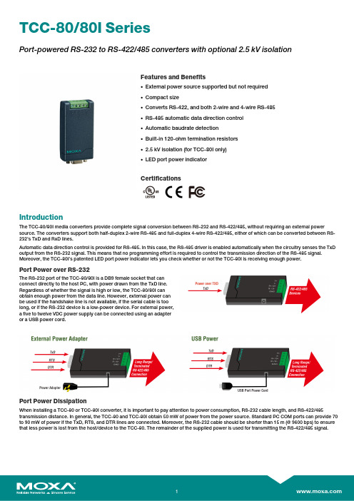
TCC-80/80I SeriesPort-powered RS-232to RS-422/485converters with optional2.5kV isolationFeatures and Benefits•External power source supported but not required•Compact size•Converts RS-422,and both2-wire and4-wire RS-485•RS-485automatic data direction control•Automatic baudrate detection•Built-in120-ohm termination resistors•2.5kV isolation(for TCC-80I only)•LED port power indicatorCertificationsIntroductionThe TCC-80/80I media converters provide complete signal conversion between RS-232and RS-422/485,without requiring an external power source.The converters support both half-duplex2-wire RS-485and full-duplex4-wire RS-422/485,either of which can be converted between RS-232’s TxD and RxD lines.Automatic data direction control is provided for RS-485.In this case,the RS-485driver is enabled automatically when the circuitry senses the TxD output from the RS-232signal.This means that no programming effort is required to control the transmission direction of the RS-485signal. Moreover,the TCC-80I’s patented LED port power indicator lets you check whether or not the TCC-80I is receiving enough power.Port Power over RS-232The RS-232port of the TCC-80/80I is a DB9female socket that canconnect directly to the host PC,with power drawn from the TxD line.Regardless of whether the signal is high or low,the TCC-80/80I canobtain enough power from the data line.However,external power canbe used if the handshake line is not available,if the serial cable is toolong,or if the RS-232device is a low-power device.For external power,a five to twelve VDC power supply can be connected using an adapteror a USB power cord.Port Power DissipationWhen installing a TCC-80or TCC-80I converter,it is important to pay attention to power consumption,RS-232cable length,and RS-422/485 transmission distance.In general,the TCC-80and TCC-80I obtain50mW of power from the power source.Standard PC COM ports can provide70 to90mW of power if the TxD,RTS,and DTR lines are connected.Moreover,the RS-232cable should be shorter than15m(@9600bps)to ensure that less power is lost from the host/device to the TCC-80.The remainder of the supplied power is used for transmitting the RS-422/485signal.Port Power and Optical IsolationThe RS-232port of the TCC-80/80I is a DB9female socket that canconnect directly to the host PC,with power drawn from the TxD line.Electrical2.5kV isolation for the TCC-80I is achieved with a photocoupler that transforms the electrical signal into light,and then re-transforms the light back into an electrical signal on the other side.Inthis way,the two electrical circuits are completely isolated from eachother.This also protects the devices from ground loop currents,reduces damage caused by data loss,and prevents damage to thecommunication interfaces.LED Port Power IndicatorIt’s easy enough to test the serial device with a multimeter todetermine that the serial device will provide enough power to themedia converter.However,it’s even easier to let the TCC-80I test thedevice for you.Simply connect the TCC-80I to the device’s RS-232port and set the SW4switch to Test mode.If the patented port powerLED indicator lights up,the TCC-80I is receiving enough power.If theLED does not light up,you will need to attach an external powersource to the TCC-80I.SpecificationsSerial InterfaceConnector TCC-80-DB9/80I-DB9:DB9maleTCC-80/80I:Terminal blockNo.of Ports2Serial Standards RS-232,RS-422,RS-485Baudrate50bps to921.6kbps(supports non-standard baudrates) Isolation TCC-80I/80I-DB9:2kVRS-485Data Direction Control ADDC®(automatic data direction control)Terminator for RS-485N/A,120ohms,120kilo-ohmsSerial SignalsRS-232TxD,RxD,RTS,CTS,DTR,DSR,DCD,GNDRS-422Tx+,Tx-,Rx+,Rx-,GNDRS-485-4w Tx+,Tx-,Rx+,Rx-,GNDRS-485-2w Data+,Data-,GNDPower ParametersInput Current TCC-80:10mA@5VDCTCC-80-DB9:10mA@5VDCTCC-80I:20mA@5VDCTCC-80I-DB9:20mA@5VDCInput Voltage5to12VDCNo.of Power Inputs1Overload Current Protection SupportedPower Consumption TCC-80/80-DB9:10mA@5VDCTCC-80I/80I-DB9:20mA@5VDCSource of Input Power Power input jackPhysical CharacteristicsHousing Plastic top cover,metal bottom plateIP Rating IP30Dimensions TCC-80/80I:42x80x22mm(1.65x3.15x0.87in)TCC-80-DB9/80I-DB9:42x91x23.6mm(1.65x3.58x0.93in) Weight50g(0.11lb)Installation DesktopEnvironmental LimitsOperating Temperature0to60°C(32to140°F)Storage Temperature(package included)-20to75°C(-4to167°F)Ambient Relative Humidity5to95%(non-condensing)Standards and CertificationsEMC EN55032/24EMI CISPR32,FCC Part15B Class AEMS IEC61000-4-2ESD:Contact:4kV;Air:8kVIEC61000-4-3RS:80MHz to1GHz:3V/mIEC61000-4-4EFT:Power:1kVIEC61000-4-5Surge:Power:1kVIEC61000-4-6CS:150kHz to80MHz:3V/m;Signal:3V/mIEC61000-4-8PFMFEnvironmental Testing IEC60068-2-1IEC60068-2-2IEC60068-2-3Safety EN60950-1,IEC60950-1Vibration IEC60068-2-6MTBFTime2,781,161hrsStandards Telcordia(Bellcore),GBWarrantyWarranty Period5yearsDetails See /warrantyPackage ContentsDevice1x TCC-80/80I Series converterCable1x USB power cord,50cmDocumentation1x quick installation guide1x warranty cardDimensions TCC-80TCC-80ITCC-80-DB9,TCC-80I-DB9Ordering InformationModel Name Isolation Serial ConnectorTCC-80–Terminal BlockTCC-80I✓Terminal BlockTCC-80-DB9–DB9TCC-80I-DB9✓DB9 Accessories(sold separately)CablesCBL-USBAP-50USB A male/2.1mm DC Jack cable,50cmConnectorsADP-RJ458P-DB9F DB9female to RJ45connectorMini DB9F-to-TB DB9female to terminal block connectorPower AdaptersPWR-12050-WPAU-S2Non-locking barrel plug,12VDC,0.5A,100-240VAC,Australia(AU)plug,0to40°C operatingtemperaturePWR-12050-WPCN-S2Non-locking barrel plug,12VDC,0.5A,100-240VAC,China(CN)plug,0to40°C operatingtemperaturePWR-12050-WPEU-S2Non-locking barrel plug,12VDC,0.5A,100-240VAC,Continental Europe(EU)plug,0to40°Coperating temperaturePWR-12050-WPUK-S2Non-locking barrel plug,12VDC,0.5A,100-240VAC,United Kingdom(UK)plug,0to40°C operatingtemperaturePWR-12050-WPUSJP-S2Non-locking barrel plug,12VDC,0.5A,100-240VAC,United States/Japan(US/JP)plug,0to40°Coperating temperature©Moxa Inc.All rights reserved.Updated Nov12,2018.This document and any portion thereof may not be reproduced or used in any manner whatsoever without the express written permission of Moxa Inc.Product specifications subject to change without notice.Visit our website for the most up-to-date product information.。
SDP-2210 2405 2603 可编程切换模式 DC 电源说明书

Remote ProgrammingSwitching Mode DC Regulated Power Supply SDP - 2210 / 2405 / 2603All values are based on the Standard ambient Temperature 25°C and Pressure 0.1Mpa.* SPECIFICATIONS ARE SUBJECT TO CHANGE WITHOUT PRIOR NOTICE *26DescriptionThis is a series of cos effective Switching Mode programmable power supplies wit full remote programming and data logging functionality.A programmable cyclic sequence of up to 20 sets of operational periods, voltage, & limiting current level can be set at the unit's keypad or by remote PC (Personal Computer) interface.Groups of control settings and cyclic sequence can be stored in the PC and input to selected power supply via RS232/RS485.With our supplied software , all the collected data of output voltage & current from each power supplies during operation can be stored as XLS (Excel™) file format in the PC.When using RS-485 , one personal computer can control and data log as many as 31 power supplies of different models of the same series.In addition to our supplied software, Command Sets and Labview® driver are supplied with the unit so that users can integrate with their own software .In the stand alone operation, the informative LCD display guides users for various functions such as preset output, programmable cyclic sequence operation.In addition to the tracking OVP (Over output Voltage Protection), there is an upper output voltage limit which prevents voltage setting over the preset limit .The output upper voltage limit is user preset.This feature prevents damage to voltage sensitive load.t h Main Features•Full remote programming and data logging.•Local or remote programmable cyclic run up to 20 sets of V , I,operational period.•Built in RS-232/485 interface which controls up to 31 units.•Supplied with software, command sets and Labview® driver.•9 user preset outputs at keypad•CC & CV indicators with auto-cross over.• 4 digit ammeter, voltmeter and power meter display.•T racking OVP and user preset max. output voltage.T ypical ApplicationsR&D works, Quality control, Production especially in applications which require groups of different settings of output voltage , current limit levels for various cyclic operation period and records of outputs readings with dynamic loading during tests.It is ideal for applications with multiple power supplies at various locations with one centralized PC control.SpecificationsSDP - 2210SDP - 2405SDP - 2603Output Voltage 1 - 20Vdc 1 - 40Vdc 1 - 60Vdc Output Current0 - 10A 0 - 5A 0 - 3A Output Rated Power200W Ripple & Noise ( Peak to Peak )30mV p-p Load Regulation 300mV 200mV 150mV Line Regulation 10mVInput Voltage 100 - 240Vac , 50Hz~ / 60Hz~Input Power 285W Power Factor ≥0.9Display Meter 4 digits - Display LCD Ammeter, Voltmeter and Power meter Meter Accuracy (±1% +5 counts for range V<5V , I<0.5A)(±1% +2 counts for range V ≥5V , I ≥0.5A)LCD Dimension 48 x 66mmCooling SystemThermostatic Control Fan Operating T emperature 0 - 40°CProtections T racking OVP (Over Voltage Protection), Current Limiting, Over T emp. Protection ApprovalsCE EMC : EN 55011 , LVD : EN 61010Dimensions (WxHxD)193 x 98 x 215mm / 7.6 x 3.9 x 8.5inch Weight3kgs / 6.6lbs®® AccessoriesUser Manual, Application Software for Windows , Labview Driver, VB Driver,Command Set, RS-232 Cable, RS-485, Connector and one 120ohm Resistor Optional Accessory RS-232 to RS-485 Adapter ( ATR-2485 )RemarkAdjustable Upper Voltage Limit, Power Factor Correction Remote Programming Specifications Communication InterfaceRS-232 and RS-485 ( up to 31 Power Supplies )Remote Programming Functionality Full control of power supply functions and data read-back Data logging Y es, with supplied software Baud Rate9600bps。
西门子 SIRIUS 3SB3 到 SIRIUS ACT 产品迁移指南说明书

Siemens SIRIUS 3SB3 to SIRIUS ACT Product Migration GuideSiemens has started the final period of the phase-out of their SIRIUS 3SB3 push button and signallingdevice range.From October 2019 SIRIUS 3SB3 will no longer beavailable. Change to SIRIUS ACT now!SIRIUS ACT – Performance in ActionSiemens SIRIUS ACT (3SU1) is the new range of push buttons, indicator lights and switches that are the perfect synergy of style, intelligence, and physical toughness. It is available in four different design lines: plastic, plastic with metal front ring, metal shiny and metal matte.An innovative snap-on concept makes the task of installing very easy – can be even done with one hand. All devices are extremely robust and provide reliable operation in the harshest environments. The various communicationoptions enable simple combinations of push buttons, signalling devices, HMI touch screens and industrial PCs.Reasons to changeNew product line SIRIUS ACT Former product line SIRIUS 3SB3Design4 modern design lines available• Plastic, black, 22mm Ø• Metal, shiny, 22mm Ø• Plastic, with matte metal front ring, 22mm Ø• Metal, matte, flat, 30mm Ø2 design lines available • Plastic, black, 22mm Ø• Metal, shiny, 22mm ØMounting• Fast, one-handed installation thanks to retentive actuator • Alignment arrows for secure connection• No special tools required• Innovative snap-on concept with clear module slots, modules cascadable• Simple, self-explanatory holder installation up to 6mm thick front plate • Actuator installation requires two hands• No clear installation marking• Special tool required for disassembling contact modules• Special adapter required for attaching 3 modules, modules not cascadable• The holder must be used differently depending on thefront plate thicknessRuggedness• Rugged and durable, even in a tough environment:–Very high resistance to water, dust and temperature thanks to IP69K degree of protection throughout (incl. IP66, IP67, IP69)–High media resistance, for example, to oils, aggressive vapors and caustic solutions• Certified for the food and beverage industry • Only a few special versions are resistant to oil • Degrees of protection:IP66 for plastic series, IP67 for metal series •No certificationReasons to changeNew product line SIRIUS ACT Former product line SIRIUS 3SB3Product portfolio• New products – complementing the standard portfolio, e.g. ID key-operated switches, sensor switches, palm push buttons, potentiometers, toggle switches, “traffic light” LEDs, EMERGENCY STOP with integrated lighting, 4-way selector switches, USB and RJ45 interfaces, adapters for standard rail mounting, locking devices for actuators and much more • Contact module characteristics:–Stackable design, possible to mount in first and second row, max. 6 contact modules• Standard portfolio only• Contact block equipping: only possible in first row, max. 3 contact modulesIO-Link, AS-i and PROFINET• Communication-capable devices available with IO-Link, AS-i or PROFINET/PROFIsafe• Only AS-i solutions availableTools• Intuitive online configurator with image-based product selection and user-friendly documentation options• Easy identification for specific configurations, thanks to unique CIN number for easy reordering • Interface to TIA Selection Tool• Comprehensive documentation in a variety of languages, e.g. data sheets, photos, dimension drawings, circuit diagrams, system manuals, operating instructions, certificates, approvals and much more• No configurator• Complex ordering process for customer-specific enclosures • Basic documentationDon't wait too long – Time is tickingTest the new communication solutions for the field and control panel with the SIRIUS ACT PROFINET starter kits:Standard starter kitSIRIUS ACT with PROFINET RS Stock No: 173-6875 Article No: 3SU1900-0XA10-0AA0Contents:Safety starter kitSIRIUS ACT with PROFINET RS Stock No: 173-6876 Article No: 3SU1900-0XB10-0AA0Contents:• 1 standard interface module • 3 terminal modules • 4 holders • 1 selector• 1 illuminated push button • 1 button• 1 indicator light • screwdriver • pair of scissors • flat ribbon cable• 1 fail-safe interface module • 3 terminal modules • 4 holders• 1 EMERGENCY STOP push button • 1 illuminated push button• 1 button• 1 indicator light • screwdriver • pair of scissors • flat ribbon cableSIRIUS ACT websiteDesignSparkSIRIUS ACT on RS Online SIRIUS 3SB3 on RS Online RS cross reference list Siemens conversion toolUseful linksVideo: Don't wait too long Video: Modern Design Video: Easy to use Video: Extremely rugged Video: Flexible communication。
- 1、下载文档前请自行甄别文档内容的完整性,平台不提供额外的编辑、内容补充、找答案等附加服务。
- 2、"仅部分预览"的文档,不可在线预览部分如存在完整性等问题,可反馈申请退款(可完整预览的文档不适用该条件!)。
- 3、如文档侵犯您的权益,请联系客服反馈,我们会尽快为您处理(人工客服工作时间:9:00-18:30)。
主
104
模块1处于慢速过压状态
1
次
106
模块1处于欠压状态
1
主
107
模块1温度不正常
1
主
108
模块1市电第一相不正常
1
主
109
模块1市电第二相不正常
1
主
110
模块1市电第三相不正常
1
主
114
模块1开关闭合
1
无
115
模块1故障
1
116…131
模块2
1
132…147
模块3
1
148…163
模块4
1
164…179
模块5
1
180…195
模块6
1
196…111
模块7
1
112…127
模块8
1
128…143
模块9
1
144…159
模块10
1
2、遥测量(以下遥测量,系数均为0.1)
点位
量名
系数
备注
0
系统电压
0.1
1
蓄电池1#电压
0.1
2
蓄电池2#电压
0.1
3
系统温度
0.1
4
电池温度
0.1
5
系统电流
0.1
6
电池电流
0.1
7
市电L1电压
0.98
进口交流板为市电L1电流
8
市电L2电压
0.98
进口交流板为市电L2电流
9
市电L3电压
0.98
进口交流板为市电L2电流
10
市电L1电流(大多数板读不出此值)
0.98
11
市电L2电流(大多数板读不出此值)
0.98
12
市电L3电流(大多数板读不出此值)
0.98
20
模块1电压
0.98
21
35
模块6电流
1.42
36
模块7电流
1.42
37
模块8电流
1.42
38
模块9电流
1.42
39
模块10电流
1.42
动态库程序:FEP_38_SIM.dll
A42故障
1
主
76
监控程序激活
1
无
77
1个模块关闭
1
次
78
m个模块关闭
1
次
79
所有模块关闭
1
主
80
所有模块故障
1
主
81
m个模块市电故障
1
主
82
所有模块市电故障
1
主
83
模块数据无法采集
1
主
100
模块1输出电压正常
0
次
101
模块1处于浮冲电状态
1
无
102
模块1处于均充状态
1
无
103
模块1处于快速过压状态
1
无
29
K10切换控制
1
无
30
模块关闭
1
主
31
模块均充
1
无
32
模块直接供给
1
次
33
服务
1
次
34
市电快速故障
1
主
35
告警取消
1
次
61
F9故障
1
主
62
F10故障
1
主
63
K10故障
1
主
69
1个模块故障
1
主
70
m个模块故障
1
主
71
模块过热
1
主
72
1个模块市电故障
1
主
73
市电故障
1
主
74
RS 485故障
1
主
75
西门子电源协议转换
一工作原理
7,8自环,9600,n,8,1
二监控量列表(
1、遥信量
序号
量名
01告警
告警等级
5
AD转换器故障
1
主
6
SPSC内部电池欠压
1
主
7
RAM数据丢失
1
主
13
1#温度传感器故障
1
主
14
2#温度传感器故障
1
主
25
SVA紧急故障信号
主
26
SVB市电故障
1
主
27
快速市电故障
1
主ቤተ መጻሕፍቲ ባይዱ
28
浮充2.33V/C
模块2电压
0.98
22
模块3电压
0.98
23
模块4电压
0.98
24
模块5电压
0.98
25
模块6电压
0.98
26
模块7电压
0.98
27
模块8电压
0.98
28
模块9电压
0.98
29
模块10电压
0.98
30
模块1电流
1.42
31
模块2电流
1.42
32
模块3电流
1.42
33
模块4电流
1.42
34
模块5电流
1.42
