std_8193
MIL-STD-1916抽样标准介绍

如在抽样阶段发现严重品质特性的不合格件,自上次合格件后的所有产品,均应执行
100%检验.
第11页,共17页。
MIL-STD-1916抽样水准转换法则
Ⅱ
55 83 116 155 228
37645 1/34 1/48 1/68 1/96
Ⅰ
27 36 53 73 96
1/34 1/48 1/68 1/96 1/136
减量
NA NA NA NA NA
1/48 1/68 1/96 1/136 1/192
第8页,共17页。
MIL-STD-1916各项抽样标准执行说明
计数值的检验结果,并不保证与计量值的检验结果具有一致性.
b.计量值抽样结果若属允收,除必须所有样本的测量结果均在规格之内,且符合表3的K法 (不良率的估计)或F法(过程变异量占公差的百分比)的判定准则,若上述两者无
法同时满足则拒收.
1) K法:适合单边规格与双边规格的产品 ·单边规格:若(U-Xbar)/δ≥K或(Xbar-L)/δ≥K,则产品允收 ·双边规格:若(U-Xbar)/δ≥K且(Xbar-L)/δ≥K,则产品允收
B
C
D
E
E
E
E
9217-17408
C
D
E
E
E
E
E
17409-30720
D
E
E
E
E
E
E
≥30721
E
E
E
E
E
E
E
第5页,共17页。
可靠性仿真在鱼雷产品上的应用
可靠性仿真在鱼雷产品上的应用王斗辉 1, 陈 欢 2, 郭 君 2, 吴 斌 2(1. 工业和信息化部 电子第五研究所, 广东 广州, 615123; 2. 中国船舶集团有限公司 第705研究所, 陕西 西安, 710077)摘 要: 针对传统可靠性试验耗时长、成本高的问题, 给出了可靠性仿真的基本内容和工作流程, 针对鱼雷产品中的典型电子组件开展可靠性仿真建模、热应力和振动应力仿真分析、故障预计和可靠性评估, 以得到产品设计薄弱环节、潜在故障信息和平均首发故障时间等。
分析结果表明, 可靠性仿真能够确保在鱼雷产品设计早期消除故障源, 从而提高鱼雷产品的鲁棒性和故障预测能力。
关键词: 鱼雷; 可靠性; 电子组件; 仿真建模; 应力分析中图分类号: TJ630 文献标识码: A 文章编号: 2096-3920(2024)01-0166-08DOI: 10.11993/j.issn.2096-3920.2023-0030Application of Reliability Simulation in Torpedo ProductsWANG Douhui1, CHEN Huan2, GUO Jun2, WU Bin2(1. CEPRI, Guangzhou 615123, China; 2. The 705 Research Institute, China State Shipbuilding Corporation Limited, Xi’an 710077, China)Abstract: The traditional reliability test is time-consuming and requires high cost. Therefore, this article provided the basic content and workflow of reliability simulation and conducted reliability simulation modeling, thermal stress simulation analysis, vibration stress simulation analysis, fault prediction, and reliability evaluation for typical electronic components in a certain torpedo product, so as to obtain weak links in product design, potential fault information, and average first failure time. The analysis results show that the reliability simulation can ensure the elimination of fault sources in the early stage of torpedo product design and thus improve torpedo product robustness and fault prediction ability.Keywords: torpedo; reliability; electronic components; simulation modeling; stress analysis0 引言随着技术的发展, 对装备可靠性水平的要求越来越高, 但对研制和生产周期的要求则越来越短,完全按传统的典型环境仿真方法对装备进行可靠性试验, 对于可靠性指标要求较高的产品, 无论是时间还是试验费用等都难以保证, 为此需要找到一种在研制初期即可针对仿真模型, 在开展建模仿真的基础上进行可靠性设计及评价的新途径。
B737-32-314 勤务前起落架、左右主起落架减震支柱
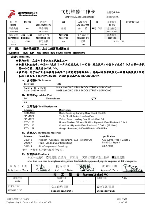
深圳航空有限责任公司 Shenzhen Airlines飞机维修工作卡 注册号/REG :MAINTENANCE JOB CARD 维修站/STA :机 型 MODELB737NG适用性 APPLICABILITY ALL ATA 章节 ATA CHAPTER32工卡编号 TC NO. B737-32-314维修类别 CATEGORYSVC 维修间隔 INTERVAL 按需 必 检 RII ■是 □否定检检号 CHECK NO. 依据文件 REFERENCE □MS □HT ■OTHERS 依据文件号 REFERENCE NO. R2006-01 R2007-05 文件版次号 VERSION NO.成本编号 COST NO.专业 SKILL AIRPL 接近盖板 ACCESSN/A区域 ZONE713 734 744标 题: 勤务前起落架、左右主起落架减震支柱SUBJECT: NLG, LEFT AND RIGHT MLG SHOCK STRUT SERVICING说明/Comments :★执行时间:在每年冬季来临前执行本工卡。
★如果飞机在换季工作指令下发前1个月内已经完成1个C 检,或在换季工作指令下发后1个月内预计要执行一个C 检,则无需执行此工作。
★在深圳、南宁和广州基地执行本换季工卡进行起落架勤务时,需要把起落架减震支柱的镜面高度在上限的基础上再加充1英寸(25.4MM)。
详细内容请参见M737-32-0702。
A 、 参考资料/ReferencesReference Title AMM12-15-31/301 MAIN LANDING GEAR SHOCK STRUT - SERVICING AMM12-15-41/301NOSE LANDING GEAR SHOCK STRUT - SERVICINGB 、 航材/Expendable PartP/N Nomenclature QTY N/AC 、 工具设备/Tool EquipmentReference Description COM-1532 Cart - Servicing, Landing Gear Shock Strut Oil SPL-1521 Tool - Strut Inflation, Landing Gear SPL-1829 Valve - Drain, Landing Gear Shock Strut Oil STD-1103 Hose - Flexible, 5/8 Inch ID, Oil or Hydraulic Fluid Resistant, 6 foot STD-1110 Container - Hydraulic Fluid Resistant, 5 Gallon (19 Liters) STD-1157 Gauge - Pressure, 0-3000 PSIG (0-20685 KPa)D 、 消耗品/Consumable MaterialReference Description SpecificationG00018 Nitrogen - Gaseous, Pressurizing, 99.5 Percent Pure A-A-59503, Type I, Grade B D00467 Fluid - Landing Gear Shock Strut BMS3-32, Type II G02314Air - Compressed, BreathingBB-A-1034说明:外场配备的氮气瓶符合要求。
模拟器件ADVFC32电压转频 频率转电压转换器使用手册说明书
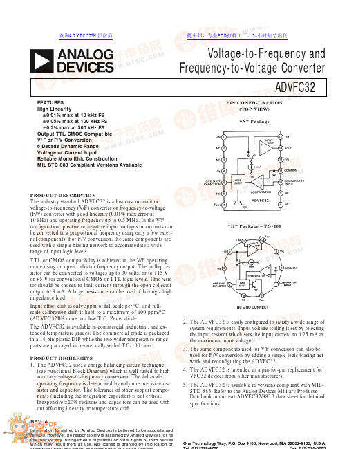
REV.AInformation furnished by Analog Devices is believed to be accurate and reliable. However, no responsibility is assumed by Analog Devices for its use, nor for any infringements of patents or other rights of third parties which may result from its use. No license is granted by implication oraVoltage-to-Frequency and Frequency-to-Voltage ConverterADVFC32One Technology Way, P.O. Box 9106, Norwood, MA 02062-9106, U.S.A.FEATURES High Linearity؎0.01% max at 10 kHz FS ؎0.05% max at 100 kHz FS ؎0.2% max at 500 kHz FS Output TTL/CMOS Compatible V/F or F/V Conversion 6 Decade Dynamic Range Voltage or Current InputReliable Monolithic ConstructionMIL-STD-883 Compliant Versions AvailablePRODUCT DESCRIPTIONThe industry standard ADVFC32 is a low cost monolithic voltage-to-frequency (V/F) converter or frequency-to-voltage (F/V) converter with good linearity (0.01% max error at 10 kHz) and operating frequency up to 0.5 MHz. In the V/F configuration, positive or negative input voltages or currents can be converted to a proportional frequency using only a few exter-nal components. For F/V conversion, the same components are used with a simple biasing network to accommodate a wide range of input logic levels.TTL or CMOS compatibility is achieved in the V/F operating mode using an open collector frequency output. The pullup re-sistor can be connected to voltages up to 30 volts, or to +15 V or +5 V for conventional CMOS or TTL logic levels. This resis-tor should be chosen to limit current through the open collector output to 8 mA. A larger resistance can be used if driving a high impedance load.Input offset drift is only 3ppm of full scale per °C, and full-scale calibration drift is held to a maximum of 100 ppm/°C (ADVFC32BH) due to a low T.C. Zener diode.The ADVFC32 is available in commercial, industrial, and ex-tended temperature grades. The commercial grade is packaged in a 14-pin plastic DIP while the two wider temperature range parts are packaged in hermetically sealed TO-100 cans.PRODUCT HIGHLIGHTS1.The ADVFC32 uses a charge balancing circuit technique (see Functional Block Diagram) which is well suited to high accuracy voltage-to-frequency conversion. The full-scale operating frequency is determined by only one precision re-sistor and capacitor. The tolerance of other support compo-nents (including the integration capacitor) is not critical.Inexpensive ±20% resistors and capacitors can be used with-out affecting linearity or temperature drift.PIN CONFIGURATION(TOP VIEW)“N” Package“H” Package – TO-100NC = NO CONNECT2.The ADVFC32 is easily configured to satisfy a wide range of system requirements. Input voltage scaling is set by selecting the input resistor which sets the input current to 0.25 mA at the maximum input voltage.3.The same components used for V/F conversion can also be used for F/V conversion by adding a simple logic biasing net-work and reconfiguring the ADVFC32.4.The ADVFC32 is intended as a pin-for-pin replacement for VFC32 devices from other manufacturers.5.The ADVFC32 is available in versions compliant with MIL-STD-883. Refer to the Analog Devices Military Products Databook or current ADVFC32/883B data sheet for detailed specifications.查询ADVFC32SH供应商捷多邦,专业PCB打样工厂,24小时加急出货ADVFC32–SPECIFICATIONS (typical @ +25؇C with V S= ؎15 V unless otherwise noted)Specifications shown in boldface are tested on all production units at final electrical test. Results from those tests are used to calculate outgoing quality levels. All min and max specifications are guaranteed,although only those shown in boldface are tested on all production units.ADVFC32KADVFC32BADVFC32SModelMin TypMax Min TypMax Min TypMax Units DYNAMIC PERFORMANCE Full Scale Frequency Range 050005000500kHz Nonlinearity 1f MAX = 10 kHz –0.01±0.01–0.01+0.01–0.01+0.01%f MAX = 100 kHz –0.05+0.05–0.05+0.05–0.05+0.05%f MAX = 0.5 MHz–0.20±0.05+0.20–0.20±0.05+0.20–0.20±0.05+0.20%Full-Scale Calibration Error (Adjustable to Zero)±5±5±5%vs. Supply(Full Scale Frequency = 100 kHz)–0.015+0.015–0.015+0.015–0.015+0.015%of FSR%vs. Temperature(Full Scale Frequency = 10 kHz)±75–100+100+150+150ppm/°CDYNAMIC RESPONSEMaximum Settling Time for Full Scale Step Input1 Pulse of New Frequency Plus 1 µs 1 Pulse of New Frequency Plus 1 µs 1 Pulse of New Frequency Plus 1 µs Overload Recovery Time 1 Pulse of New Frequency Plus 1 µs 1 Pulse of New Frequency Plus 1 µs 1 Pulse of New Frequency Plus 1 µsANALOG INPUT AMPLIFIER (V/F Conversion)Current Input Range 0+0.250+0.250+0.25mA Voltage Input Range–100–100–10V 20.250.250.25mA× R IN 3× R IN 3× R IN 3Differential Impedance 300 k Ω||10 pF 2 M Ω||10 pF 300 k Ω||10 pF 2 M Ω||10 pF 300 k Ω||10 pF 2 M Ω||10 pF Common-Mode Impedance 300 M Ω||3 pF750 M Ω||3 pF 300 M Ω||3 pF 750 M Ω||10 pF300 M Ω||3 pF 750 M Ω||10 pFInput Bias Current Noninverting Input 402504025040250nA Inverting Input –100±8+100–100±8+100 –100±8+100nA Input Offset Voltage(Trimmable to Zero)2, 3444mV vs. Temperature (T MIN to T MAX )303030µV/°CSafe Input Voltage±V S±V S±V SCOMPARATOR (F/V Conversion)Logic “0” Level –V S –0.6–V S –0.6–V S –0.6V Logic “1” Level +1+V S+1+V S+1+V S V Pulse Width Range 40.10.15/f MAX0.10.15/f MAX0.10.15/f MAX µsInput Impedance 50 k Ω||10 pF250 k Ω50 k Ω||10 pF250 k Ω50 k Ω||10 pF250 k ΩOPEN COLLECTOR OUTPUT (V/F Conversion)Output Voltage in Logic “0”I SINK = 8 mA0.40.40.4V Output Leakage Current in Logic “1”111µA Voltage Range+300+300+30V Fall Times (Load = 500 pF and I SINK = 5 mA)400400400ns AMPLIFIER OUTPUT (F/V Conversion)Voltage Range (0 mA ≤I O ≤7 mA)0+100+100+10V Source Current (0≤V O ≤7 V)101010mA Capacitive Load (Without Oscillation)100100100pF Closed Loop Output Impedance 111ΩPOWER SUPPLY Rated Voltage ±15±15±15V Voltage Range ±9±18±9±18±9±18V Quiescent Current 686868mA TEMPERATURE RANGE Specified Range 0+70–25+85–55+125°C Operating Range –25+85–55+125–55+125°C Storage –25+85–65+150–65+150°CPACKAGE OPTIONS Plastic DIP (N-14)ADVFC32KNTO–100 (H-10A)ADVFC32BH ADVFC32SHNOTES 1Nonlinearity defined as deviation from a straight line from zero to full scale, expressed as a percentage of full scale.2See Figure 3.3See Figure 1.4f MAX expressed in units of MHz.Specifications subject to change without notice.ADVFC32UNIPOLAR V/F, POSITIVE INPUT VOLTAGEWhen operated as a V/F converter, the transformation from voltage to frequency is based on a comparison of input signal magnitude to the 1 mA internal current source.A more complete understanding of the ADVFC32 requires a close examination of the internal circuitry of this part. Consider the operation of the ADVFC32 when connected as shown inFigure 1. At the start of a cycle, a current proportional to theFigure 1.Connection Diagram for V/F Conversion,Positive Input Voltageinput voltage flows through R3 and R1 to charge integration capacitor C2. As charge builds up on C2, the output voltage of the input amplifier decreases. When the amplifier output volt-age (Pin 13) crosses ground (see Figure 2 at time t 1), thecomparator triggers a one shot whose time period is determinedFigure 2.Voltage-to-Frequency Conversion Waveformsby capacitor C1. Specifically, the one shot time period (in nano-seconds) is:t OS ≅ (C l + 44 pF ) × 6.7 k ΩDuring this period, a current of (1 mA – I IN ) flows out of the in-tegration capacitor. The total amount of charge depleted during one cycle is, therefore (1 mA – I IN ) × t OS . This charge is replacedduring the remainder of the cycle to return the integrator to its original voltage. Since the charge taken out of C2 is equal to the charge that is put on C2 every cycle,(1 mA – I IN ) × t OS = I IN ×1FOUT–t OSor, rearranging terms,F OUT =I IN1mA ×t OS The complete transfer equation can now be derived by substi-tuting I IN = V IN /R IN and the equation relating C1 and t OS . The final equation describing ADVFC32 operation is:V II N /R IN1mA ×C 1+44pF ()×6.7k ΩComponents should be selected to optimize performance over the desired input voltage and output frequency range using the equations listed below:3.7×10⁷pF /secF OUT FS –44pFC 2 =10–4Farads /secF OUT FS1000pF minimum ()R IN =V IN FS 0.25mA R 2 ≥+V LOGIC 8mABoth R IN and C 1 should have very low temperature coefficients as changes in their values will result in a proportionate change in the V/F transfer function. Other component values and tem-perature coefficients are not critical.CAUTIONESD (electrostatic discharge) sensitive device. Electrostatic charges as high as 4000V readily accumulate on the human body and test equipment and can discharge without detection.Although the ADVFC32 features proprietary ESD protection circuitry, permanent damage may occur on devices subjected to high energy electrostatic discharges. Therefore, proper ESD precautions are recommended to avoid performance degradation or loss of functionality.ORDERING GUIDEPartGain Tempco Temp Range Package Number 1ppm/؇C ؇C Option ADVFC32KN ±75 typ 0 to +7014-Pin Plastic DIP ADVFC32BH ±100 max –25 to +85TO-100ADVFC32SH±150 max–55 to +125TO-100NOTE 1For details on grade and package offerings screened in accordance withMIL-STD-883, refer to the Analog Devices Military Products Databook or current ADVFC32/883B data sheet.Table I. Suggested Values for C 1, R IN and C 2V IN FS F OUT FS C 1R IN C 21 V 10 kHz 3650 pF 4.0 k Ω0.01 µF 10 V 10 kHz 3650 pF 40 k Ω0.01 µF 1 V 100 kHz 330 pF 4.0 k Ω1000 pF 10 V100 kHz330 pF40 k Ω1000 pFADVFC32F/V CONVERSIONAlthough the mathematics of F/V conversion can be very com-plex, the basic principle is easy to understand. Figure 4 shows the connection diagram for F/V conversion with TTL input logic levels. Each time the input signal crosses the comparator threshold going negative, the one shot is activated and switches 1 mA into the integrator input for a measured time period (de-termined by C1). As the frequency increases, the amount of charge injected into the integration capacitor increases propor-tionately. The voltage across the integration capacitor is stabi-lized when the leakage current through R1 and R3 equals the average current being switched into the integrator. The net re-sult of these two effects is an average output voltage which is proportional to the input frequency. Optimum performance can be obtained by selecting components using the same guidelinesand equations listed in the V/F conversion section.Figure 4.Connection Diagram for F/V Conversion, TTL InputDECOUPLINGDecoupling power supplies at the device is good practice in any system, but absolutely imperative in high resolution applica-tions. For the ADVFC32, it is important to remember where the voltage transients and ground currents flow. For example,the current drawn through the output pulldown transistor origi-nates from the logic supply, and is directed to ground through Pin 11 (Pin 8 of TO-100). Therefore, the logic supply should be decoupled near the ADVFC32 to provide a low impedance re-turn path for switching transients. Also, if there is a separate digital ground it should be connected to the analog ground at the ADVFC32. This will prevent ground offsets that could be created by directing the full 8 mA output current into the analog ground, and subsequently back to the logic supply.Although some circuits may operate satisfactorily with the power supplies decoupled at only one location on each board,this practice is not recommended for the ADVFC32. For best results, each supply should be decoupled with 0.1 µF capacitor at the ADVFC32. In addition, a larger board level decoupling capacitor of 1 µF to 10 µF should be located relatively close to the ADVFC32 on each power supply.COMPONENT TEMPERATURE COEFFICIENTSThe drift specifications of the ADVFC32 do not include tem-perature effects of any of the supporting resistors or capacitors.The drift of the input resistors R1 and R3 and the timing ca-pacitor C1 directly affect the overall temperature stability. In theInput resistance R IN is composed of a fixed resistor (R1) and a variable resistor (R3) to allow for initial gain error compensa tion.To cover all possible situations, R3 should be 20% of R IN , and R1 should be 90% of R IN . This allows a ±10% gain adjustment to compensate for the ADVFC32 full-scale error and the toler-ance of C1.If more accurate initial offset is required, the circuit of R4 and R5 can be added. R5 can have a value between 10 k Ω and 100 k Ω, and R4 should be approximately 10 M Ω. The amount of current required to trim zero offset will be relatively small, so the temperature coefficients of these resistors are not critical. If large offsets are added using this circuit, temperature drift of both of these resistors is much more important.BIPOLAR V/FBy adding another resistor from Pin 1 (Pin 2 of TO-100 can) to a stable positive voltage, the ADVFC32 can be operated with a bipolar input voltage. For example, an 80 k Ω resistor to +10 V causes an additional current of 0.125 mA to flow into the inte-grator so that the net current flow to the integrator is positive even for negative input voltages. At negative full-scale input voltage, 0.125 mA will flow into the integrator from V IN cancel-ling out the 0.125 mA from the offset resistor, resulting in an output frequency of zero. At positive full scale, the sum of the two currents will be 0.25 mA and the output will be at its maxi-mum frequency.UNIPOLAR V/F, NEGATIVE INPUT VOLTAGEFigure 3 shows the connection diagram for V/F conversion of negative input voltages. In this configuration full-scale output frequency occurs at negative full-scale input, and zero outputfrequency corresponds to zero input voltage.Figure 3.Connection Diagram for V/F Conversion,Negative Input VoltageA very high impedance signal source may be used since it only drive the noninverting integrator input. Typical input imped-ance at this terminal is 250 M Ω or higher. For V/F conversion of positive input signals the signal generator must be able to source 0.25 mA to properly drive the ADVFC32, but for nega-tive V/F conversion the 0.25 mA integration current is drawn from ground through R1 and R3.Circuit operation for negative input voltages is very similar to positive input unipolar conversion described in the previous sec-tion. For best operating results use component equations listedADVFC32100 ppm/°C capacitor may result in a maximum overall circuit gain drift of:100 ppm/°C (ADVFC32BH) + 100 ppm/°C (C1)+ 10 ppm/°C (R IN ) = 210 ppm/°CAlthough R IN and C1 have the most pronounced effect on tem-perature stability, the offset circuit of resistors R4 and R5 may also have a slight effect on the offset temperature drift of the cir-cuit. The offset will change with variations in the resistance of R4 and supply voltage changes. In most applications the offset adjustment is very small, and the offset drift attributable to this circuit will be negligible. In the bipolar mode, however, both the positive reference and the resistor used to offset the signal range will have a pronounced effect on offset drift. A high quality reference and resistor should be used to minimize offset drift errors.Other circuit components do not directly influence temperature performance as long as their actual values are not so different from nominal value as to preclude operation. This includes integration capacitor C2. A change in the capacitance value of C2 results in a different rate of voltage change across C2, but this is compensated by an equal effect when C2 is discharged by the switched 1 mA current source so that no net effect occurs.The temperature effects of the components described above are the same when the ADVFC32 is configured for negative or bi-polar input ranges, or F/V conversion.OTHER CIRCUIT CONSIDERATIONSThe input amplifier connected to Pins 1, 13, and 14 is not a standard operational amplifier. Although it operates like an op amp in most applications, two key differences should be noted.First, the bias current of the positive input is typically 40 nAwhile the bias current of the inverting input is ±8 nA. Therefore,any attempt to cancel input offset voltage due to bias currents by matching input resistors will create worse offsets. Second, the output of this amplifier will sink only 1 mA, even though it will source as much as 10 mA. When used in the F/V mode, the am-plifier must be buffered if large sink currents are required.MICROPROCESSOR OPERATED A/D CONVERTERWith the addition of a few external components the ADVFC32can be used as a ±10 V A/D microprocessor front end. Although the nonlinearity of the ADVFC32 is only 0.05% maximum (0.01% typ), the resolution is much higher, allowing it to be used in 16-bit measurement and control systems where a mono-tonic transfer function is essential. The resolution of the circuit shown in Figure 5 is dependent on the amount of time allowed to count the ADVFC32 frequency output. Using a full scale fre-quency of 100 kHz, an 8-bit conversion can be made in about 10 ms, and a 2 second time period allows a 16-bit measurement,including offset and gain calibration cycles.As shown in Figure 5, the input signal is selected via the AD7590input multiplexer. Positive and negative references as well as a ground input are provided to calibrate the A/D. This is very im-portant in systems subject to moderate or extreme temperature changes since the gain temperature coefficient of the ADVFC32is as high as ±150 ppm/°C. By using the calibration cycles, the A/D conversion will be as accurate as the references provided.The AD542 following the input multiplexer provides a high im-pedance input (1012 ohms) and buffers the switch resistance from the relatively low impedance ADVFC32 input.If higher linearity is required, the ADVFC32 can be operated at 10 kHz, but this will require a proportionately longer conver-sion, time. Conversely, the conversion time can be decreased at the expense of nonlinearity by increasing the maximum fre-quency to as high as 500 kHz.HIGH NOISE IMMUNITY, HIGH CMRR ANALOG DATA LINKIn many applications, a signal must be sensed at a remote site and sent through a very noisy environment to a central location for further processing. In these cases, even a shielded cable may not protect the signal from noise pickup. The circuit of Figure 6provides a solution in these cases. Due to the optocoupler andFigure 5.High Resolution, Self-Calibrating, Microprocessor Operated A/D Convertervoltage-to-frequency conversion, this data link is extremelyinsensitive to noise and common-mode voltage interference. For even more protection, an optical fiber link substituted for the HCPL2630 will provide common-mode rejection of more than several hundred kilovolts and virtually total immunity to electri-cal noise. For most applications, however, the frequency modu-lated signal has sufficient noise immunity without using an opticalADVFC32C 754c –5–2/89P R I N T E D I N U .S .A.Figure 6.High Noise Immunity Data Linkfiber link, and the optocoupler provides common-mode isolation up to 3000 V dc.The data link input voltage is changed in a frequency modulated signal by the first ADVFC32. A 42.2 k Ω input resistor and a 100 k Ω offset resistor set the scaling so that a 0 V input signal corresponds to 50 kHz, and a 10 V input results in the maxi-mum output frequency of 500 kHz. A high frequency opto-coupler is then used to transmit the signal across any common-mode voltage potentials to the receiving ADVFC32. The opto-coupler is not necessary in systems where common-mode noise is either very small or a constant low level dc voltage. In systems where common-mode voltage may present a problem, the con-nection between the two locations should be through the opto-coupler; no power or ground connections need to be made.The output of the optocoupler drives an ADVFC32 hooked up in the F/V configuration. Since the reconstructed signal at Pin 10 has a considerable amount of carrier feedthrough, it is desir-able to filter out any frequencies in the carrier range of 50 kHz to 500 kHz. The frequency response of the F/V converter is only 3 kHz due to the pole made by the integrator, so a second 3 kHz filter will not significantly limit the bandwidth. With the simple one pole filter shown in Figure 6, the input to output 3 dB point is approximately 2 kHz, and the output noise is less than15 mV. If a lower output impedance drive is needed, a two pole active filter is recommended as an output stage.Although the F/V conversion technique used in this circuit is quite simple, it is also very limited in terms of its frequency re-sponse and output ripple. The frequency response is limited by the integrator time constant and while it is possible to decrease that time constant, either signal range or output ripple must be sacrificed. The performance of the circuit of Figure 6 is shown in the photograph below. The top trace is the input signal, the middle trace is the frequency-modulated signal at theoptocoupler’s output, and the bottom trace is the recoveredsignal at the output of the F/V converter.OUTLINE DIMENSIONSDimensions shown in inches and (mm).14-Pin Plastic DIP PackageTO-100 Package。
mil-std-1916(中文版)

一、前言为强调过程品管与持续不断改进的重要性,美军于1996年推出新版的抽样标准:MIL-STD-1916,用以取代MIL-STD-105E作为美军采购时主要选用的抽样标准。
本标准的目的在鼓励供应商建立品质系统与使用有效的过程控制程序,以取代最终产品的抽样方式,希望供应商远离以AQL(Acceptable Quality Level)为主的抽样计划,而以预防性的品质制度代替它,故本标准之愿景在建立不合格过程改进之制度,而非最终检验品质之水准。
MTL-STD-1916与MIL-STD-105E抽样标准不同之处,主要有以下几点:1、抽样计划以单次抽样(含加严、正常及减量)为主,删除双次与多次抽样,抽样以“0收1退”(ZBA Zero Based Acceptance)当做判定标准,强调不允许不良品之存在。
2、建立持续不断改善之品质系统制度与善用多项品质改善工具。
3、以预防代替检验,在过程中执行统计过程品管(SPC)。
4、对计数、计量及连续性抽样作业均可适用(分别有三种抽样表),不再像以往MIL-STD-105E仅限于计数值抽样,MIL-STD-414仅限于计量值抽样与MIL-STD-1235仅限于连续性抽样(以上标准美军均已废止)。
5、把抽样视为一种浪费的行为,如供应商可提出不同产品的接收计划,如获顾客同意后,则可按约定的接收方式办理验收。
6、MIL-STD-1916强调供应商品质系统的建立,以预防为主,而MIL-STD-105E强调顾客的抽样技术,避免接收不合格件。
此外,以往最常用的MIL-STD-105E抽样标准,使用的查检表上就有加严、正常及减量等对应查检表数十个,在运用上并不是很方便,而MIL-STD-1916所使用的表格(含计数、计量及连续性抽样),就只有4个,在使用的简便性上,已有大大的改善。
二、适用范围1、本标准所提供的品质计划与程序,不能减轻供应商满足顾客需求的责任,供应商必须建立品质系统,包括制造程序,品管监控等作业,用以生产符合顾客品质要求的产品。
MIL-STD-1916 抽样计划简介

MIL-STD-1916
二、MIL-STD-1916與MIL-STD-105E不同之處有下列幾項:
1. 抽樣計劃以單次為主(含加嚴、正常、減量) ,刪除雙次與多次抽樣,抽 樣以「0收1退」(ZBA,Zero Based Acceptance)當做判定標準,強調不允 許不良品存在。 2. 於計數、計量、連續性抽樣作業均可適用(分別有三種抽樣表,不再像以 往MIL-STD-105E僅限於計數值抽樣計劃、MIL-STD-414僅限於計量值抽 樣計劃、MIL-STD-1235僅限於連續性抽樣。 3. 以前最常用的MIL-STD-105E抽樣標準,使用之查檢表就分正常、加嚴、 減量等十數個表格,在運用上不是很方便,而MIL-STD-1916所使用之表 格(含計數、計差、連續抽樣)就只分4種,在使用之簡便性上,已有很大 的改善。 4. MIL-STD-1916強調供應商品質系統之建立,要以預防為主,而 MIL-STD-105E強調顧客之抽樣計劃,避免接收不合格件
3. 品質系統之建立,可依據ISO 9000,MIL-Q-9858等標準加以規劃,無論選擇那一種 標準,品質系統必須以預防為主體,且需符合下列之目標:
(1) (2) (3) (4) 。 (5) (6) 影響品質之工作者必須瞭解品質系統之運作程序。 產品必須符合或超越顧客需求。 強調預防性之製程差異性分析與不良率分析。 當疪病產生時,必須立即尋找失效之發生原因與疪病來源,且採取有效的矯正措施 使用統計方法與問題解析手法,用以降低製程變異量,改善製程能力與產品品質。 保存紀綠,用以證實品質計劃與製程管制的有效性。
各類抽樣計劃均不允許不良品之發生,如發生則處理方式如下: (1) (2) 5. 計量及計數型抽樣計劃,該批拒收,且需即進行矯正及預防措施。 連續型抽樣計劃,該批拒收,並應執行全數篩選與即進行矯正及預防措施。 抽樣方法:
MIL-STD-1916计量型抽样检查方案

标题:MIL-STD-1916计量型抽样检查方案
1、目的:明确MIL-STD-1916计量型抽样作业方法,并通过抽样检查的结果来监视产品质量情况。
2、适用范围:用于检验批用计量质量指标表示其质量状况的场合。
3、定义:
1.验证水平(VL):顾客对产品品质所需求的“重要性水准"或“品质特性有效性"的陈述,是一种对生产者品质保证努力的衡量方式,表示质量保证的努力程度。共有Ⅰ、Ⅱ、Ⅲ、Ⅳ、Ⅴ、Ⅵ、Ⅶ七个水平。
3.对抽样产品的质量特性进行测量,并对抽样检查结果进行判定:
a)若发现1个或1个以上的不合格品(测量结果超出其允许公差范围的产品),则该批产品“拒收”。
b)若没有发现不合格品,则需采用“K法”(不良率的估计)或“F法”(过程变异量占公差的百分比)的作进一步判定,若这两种判定准则同时都满足(同时判定为“允收”)则该批产品“允收”,若仅一种满足或两种都无法满足则“拒收”。具体判定方法如下:
113
87
64
44
29
18
9
4
备注:
1)当批量比样本量小则全检。
2)正常检验的样本量大小即产品验证水平(VL)与样本代码(CL)对应位置的数值。
3)加严检验的样本量大小即产品验证水平(VL)与样本代码(CL)对应位置左边的数值。
4)减量检验的样本量大小即产品验证水平(VL)与样本代码(CL)对应位置右边的数值。
c)加严转换正常:当下列两个件均符合时,则由加严检验转换正常检验。
1不合格件的疵病原因已完成纠正;
2且连续5批被允收。
d)正常转换减量:当下列三条件均符合时,则由正常检验转换减量检验(即样本量选择为“表-2”中产品验证水平(VL)与样本代码(CL)对应位置右边的数值)。
铁舾装标准
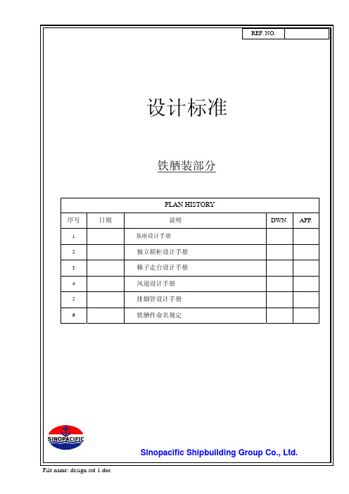
PAGE NO. 2REF. NO目录DATE 序号DESCRIPTION 页次1 设计标准(基座设计手册) 3 - 132 设计标准(独立箱柜设计手册)14 - 153 设计标准(梯子走台设计手册)26 - 414 设计标准(风道设计手册)42 - 615 设计标准(排烟管设计手册)62 - 736 STRUCTURE NAME 制定规定 74 - 81File name: design std-1.doc1. 考虑到振动,下列的主机和辅助机械,在船体设计当中主要依赖于基座设置。
DATE4. 对于基座的加强筋的设置,应延长加固到强结构构件。
5.除去特殊情况以外,角钢的螺栓孔距离如下所示.6. 下列主机和辅机除图中已标记外,螺栓孔应随着螺栓直径的使用改变如下:螺栓尺寸 螺栓孔 螺栓尺寸 螺栓孔 M6 7Ø (M22) 25 ØM8 9.5 Ø M24 27 ØM10 12 Ø (M27) 30 ØM12 14 Ø M30 33 Ø (M14) 17 Ø (M33) 37 ØM16 19 Ø M36 39 ØM20 23 Ø M42 45 ØL L1 L250 30 2065 35 3075 45 30100 55 45130 70 60150 80 707. 螺栓的长度在和螺母连接以后应给出8. 所有的螺栓和螺母除了标记了制造厂图提供的特殊的材料以外 ,Q235-A 9. 下列设备安装使用单螺母,其它的用双螺母。
1)备用螺旋桨轴2-3个 螺齿2-3个 螺齿弹簧垫圈设计标准(基座设计手册)REF. NO.DATE11. 连接在舷侧的基座的支撑腿尽可能连到船体结构,同时满足船级社的要求。
12.如果是钢板形式基座,为了焊接,基座的里面应设置人孔 .13. 为使管路不碰基座,管系布置时要研讨商议,基座设计也要跟管子设计商议,然后确定。
北京常规标准玻璃仪器cas号
北京常规标准玻璃仪器CAS号1. 介绍北京常规标准玻璃仪器是一种用于实验室、生产线和工业场所的玻璃仪器。
它具有优良的耐腐蚀性能,适用于化学反应、蒸馏、萃取等操作。
为了对这些玻璃仪器进行准确的鉴定和识别,国际化学品标识系统对其进行了统一的CAS号编码。
CAS号是化学抽象服务号,是国际化学文摘号(Chemical Abstracts Service)分配的一种号码,用于标识化学物质的唯一编号,方便科研人员快速准确地查询和识别化学物质。
2. CAS号的作用CAS号作为一种全球通用的化学物质标识号,具有重要的作用。
它可以唯一地标识同一种化学物质,避免了因命名不统一或者名称重复而导致的混淆。
CAS号可以快速准确地进行数据库查询,帮助科研人员获取相关化学物质的详细信息,如物理性质、化学性质、危险性等。
CAS号还是全球化工行业的贸易凭证和进出口报关的必备信息,对于推动全球化工品质量和安全生产具有重要意义。
3. 北京常规标准玻璃仪器CAS号的查询方法3.1 在线查询目前,有多种化学物质数据库提供CAS号查询的在线服务,如美国化学文摘社(CAS)、化学工业出版社(ACD)等。
用户可以通过输入化学品名称或结构式等信息,即可获取CAS号。
另外,一些商业化学品供应商全球信息湾也提供CAS号查询功能,用户可以通过输入商业化学品名称或编码,即可获取CAS号。
3.2 实验室实测对于一些特殊的北京常规标准玻璃仪器,其CAS号可能并未在数据库中记录,这时需要通过实验室的分析测试手段来获取CAS号。
一般来说,可以通过质谱仪、红外光谱仪等仪器对化学物质进行鉴定,并结合相关的识别技术,最终获得CAS号。
4. 北京常规标准玻璃仪器CAS号的重要性北京常规标准玻璃仪器CAS号的准确获取和使用具有重要的意义。
它可以帮助科研人员快速了解所使用的化学试剂的性质和风险,避免了使用错误试剂导致的实验失败或者安全事故。
它是国际合作与交流的桥梁,通过CAS号的统一标识,实现了全球范围内对化学物质信息的快速传递和共享,促进了全球化工行业的发展和合作。
铽镝铁磁致伸缩材料-最新国标
铽镝铁大磁致伸缩材料1范围本文件规定了铽镝铁大磁致伸缩材料的牌号、要求、试验方法、检验规则和包装、标志、运输、贮存及随行文件。
本文件适用于定向凝固工艺生产的铽镝铁大磁致伸缩材料。
2规范性引用文件下列文件对于本文件的应用是必不可少的。
其中,凡是注日期的引用文件,仅注日期的版本适用于本文件。
凡是不注日期的引用文件,其最新版本(包括所有的修改单)适用于本文件。
GB/T2828.1—2012计数抽样检验程序第1部分:按接受质量限(AQL)检索的逐批检验抽样计划GB/T7314金属材料室温压缩试验方法GB/T8170数值修约规则与极限数值的表示和判断GB/T9637电工术语磁性材料与元件GB/T13012软磁材料直流磁性能的测量方法GB/T17803稀土产品牌号表示方法GB39176稀土产品的包装、标志、运输和贮存3术语和定义GB/T9637界定的以及下列术语和定义适用于本文件。
3.1磁致伸缩系数magnetostrictive coefficient在外磁场作用下产生的尺寸相对变化量(应变),用λ表示。
测量方向与外加磁场方向平行时所测得的磁致伸缩系数为平行磁致伸缩系数,用λ∥表示。
3.2动态磁致伸缩系数dynamic magnetostrictive coefficient平行磁致伸缩系数随磁场变化的变化率称为动态磁致伸缩系数,用d33表示,单位为m/A。
33=B∥∕d3.3磁致伸缩温度系数temperature coefficient of magnetostriction在一定磁场与预压应力下,平行磁致伸缩系数随温度变化的变化率,用αλ表示,单位为1/℃。
=B∥∕d3.4磁致伸缩不均匀度nonuniformity of magnetostriction一定匀强磁场下,磁致伸缩材料不同位置的平行磁致伸缩系数(λ∥N )与其平均值(∥ =(λ∥1+λ∥2+λ∥3+……+λ∥N )/N )的偏离程度,用N表示。
银瓷杯中银及有害元素的检测研究
银瓷杯中银及有害元素的检测研究收稿日期:2023-11-01;修回日期:2023-12-29基金项目:山东省计量科学研究院科技项目(sdimkj202218)作者简介:刘雪松(1987—),男,高级工程师,硕士,从事贵金属饰品检测及材料性能研究;E mail:lxs_198618@163.com刘雪松1,2,黄 准2,3,李桂华1,2,孔祥冰2,4,潘 臖1,刘海彬1,2,祝培明1,2(1.山东省计量科学研究院;2.国家黄金钻石制品质量检验检测中心;3.山东省计量检测中心;4.山东省社会公正计量行)摘要:银瓷杯作为一种新产品,款式和风格多样,满足了人们的特色需求,得到市场的青睐。
实验采用X射线荧光光谱法、ICP光谱法、电位滴定法、显微摄影系统对银瓷杯进行了分析测试和观察。
结果表明:银瓷杯因表面银层较薄,X射线荧光光谱法难以获得准确检测结果,可选用电位滴定法进行测试。
银瓷杯中常检测到铅,为降低产品中铅含量,建议使用无铅釉料。
关键词:银瓷杯;银;有害元素;X射线荧光光谱法;ICP光谱法;溶出量 中图分类号:TD926.3 文章编号:1001-1277(2024)02-0099-04文献标志码:Adoi:10.11792/hj20240220引 言陶瓷是中国的传统文化元素,在历史上对世界文明发展做出了重要贡献。
随着时代的发展,陶瓷因其极好的力学性能、抗高温特性和耐化学腐蚀性,广泛用于日常生活中。
人民生活水平的提高和对健康生活品质的追求,对陶瓷制品提出了更高要求。
将银与陶瓷相结合,制作成银瓷杯,作为一种新产品,因其款式和风格多样,满足了人们的特色需求,越来越得到人们的青睐。
但是,经黏接或镶嵌的银瓷杯,在温度和湿度变化的使用环境中,银容易从陶瓷制品上脱落,影响银瓷杯的整体装饰效果,降低了银瓷杯的观赏价值和收藏价值,因此加工工艺还需要继续改进。
此外,生产销售企业及消费者越来越关注该产品是否含有害元素及其是否对人体有危害[1-2]。
HD FIRE PROTECT PVT. LTD. 水桶火灾保护系统预制水桶装载系统-竖直 水平类型

BLADDER TANK PROPORTIONING SYSTEM PRE-PIPEDTANK MOUNTING Vertical or Horizontal TYPECONCENTRATEFor Vertical Tank:STORAGE CAPACITY 140 litres to 7500 litres (36 TO 2000 gallon (US))For Horizontal Tank: 140 litres to 15000 litres(36 to 4000 gallon (US))WORKING 30 psi (2.1 bar) to PRESSURE 175 psi (12 bar)OPERATING 35.6˚F (2˚C) to TEMPERATURE 167˚F (75˚C)FACTORY HYDRO As per ASME codeTEST PRESSURE FLOW Refer Ratio ControllerProduct Data Sheet-HD 263VESSELCarbon Steel as per ASME CONSTRUCTION Code Section VIII Div 1, forunfired pressure vessels CE MarkOptional ASME “U” STAMP Optional BLADDERBuna-NEXTERNAL PIPING Water side: Carbon Steel Seamless Pipe Sch.40 Foam Concentrate side:Stainless Steel Sch.40RATIOWafer type with Stainless CONTROLLER Steel 304/CF8 standard supply Optional: Stainless Steel 316/CF8M or BronzeOptional - Flanged Type VENT AND DRAIN Ball valveAPPROVALS UL-Listed or FM Approved OPTIONAL SUPPL Y Refer to page 3FINISH Red RAL 3001ORDERING S pecify:INFORMATION 1. Tank type, vertical or horizontal2. Storage capacity3. Model number , size of ratio controller with flow and pressure4. Type of foam concentrate to be used and percentage of induction required5. Optional items6. UL or FM ApprovalRequirementTECHNICAL DATAAPPLICATIONThe Bladder Tank Foam Proportioning System utilises water pressure to inject foam concentrate into water supply and automatically proportions foam concentrate over wide range of flow and pressure, with very low pressure drop. This system does not require a foam concentrate supply pump.SPECIFICATIONThe Bladder Tank Foam Proportioning Systems are available with vertical and horizontal bladder tanks. The carbon steel tanks are designed and constructed in accordance with ASME Code Section Vlll Div.1 for unfired pressure vessels.The maximum working pressure is 12 bar (175 psi). The vertical tank assembly is supported by legs welded to tank with provision for anchoring. The horizontal tanks are supported by two saddles welded to the tank and drilled for anchoring. Tank is provided with lifting lugs.The system is supplied with pressure vessel, bladder , fill and drain valve for water and foam concentrate, ratio controller and vent valve.Note: The above images are for representative purpose, actual product may vary depending on the required accessories & specifications.Ladder and sight gauge assembly are supplied as optional items on request.All valves are labeled showing normal working position and function. All tanks are oversized for allowing thermal expansion of the foam concentrate, if any. PRINCIPLE OF OPERATIONThe instructions for filling are provided with the equipment. Once the main water flow is established and water inlet and foam outlet valves are opened, the water enters the area between vessel wall and bladder, applying pressure to the bladder. The foam concentrate is forced out of the bladder through the foam concentrate outlet pipe and into the ratio controller through metering orifice. The concentrate pressure and water inlet pressure at ratio controller will be same, as the main water supply pressure is utilised to expel the foam from the bladder. The water flowing through the ratio controller jet creates a low pressure area for foam concentrate. This injects the concentrate in to the ratio controller through an accurate sized orifice proportioned to water venturi. This ensures correct proportioning over a wide range of flow condition.The bladder tank proportioning system operates on same principle as that of a balance pressure proportioning system. In bladder system, the bladder is used as diaphragm to separate the water and foam concentrate within the tank. The foam concentrate is injected into the ratio controller utilising water pressure.The system is also supplied with foam concentrate control valve as an optional item. The valve allows concentrate flow only when minimum of 2.1 kg/ sq.cm water pressure is established in the system. For pressure drop and flow characteristics refer catalogue of ratio controller.HD FIRE Bladder tanks and proportioners are UL Listed and FM Approved with various HD foam concentrates, refer individual listing and approval data.“U’ stamp (The American Society of Mechanical Engineers- ASME) code stamp. This ASME certification is optional.Bladder tanks 900 Liters and larger are CE marked on conformance with the European Pressure Equipment Directives. CE marking is optional. SELECTION OF HORIZONTAL/ VERTICAL BLADDER TANKSAdvantages of Horizontal bladder tanks(i) Better stability than vertical tank in earthquakeprone area(ii) Easier to refill than vertical tanks(iii) Easy to transport, store and install(iv) Large Capacity Advantages of Vertical bladder tanks(i) Require less floor space than horizontal tanks INSTALLATION, INSPECTION AND MAINTENANCEAn installation, inspection and maintenance manual is packed with each unit. The manual provides detail schematic, initial procedure,inspection and maintenance procedures. The instruction manual must be read carefully and followed during installation and commissioning of the system.After few initial successful tests an authorised person must be trained to perform inspection and testing of the system. It is recommended to carry out physical inspection of the system regularly, the inspector should verify that no damages have taken place to any component and all the valves are in their proper position as per the system requirement. The system should be fully tested at least once in a year and in accordance with applicable NFPA code or in accordance to the guidelines of the organisation having local jurisdiction.Do not turn off the system or any valve to repair or test the system, without placing a roving Fire Patrol in the area covered by the system. The patrol should continue until the system is put back in service. Also inform the local security personnel and the control room so that a false alarm is not signalled. CAUTION1) Do not weld on the tank as it may damage thebladder fitted inside the tank.2) Release pressure before an inspection andmaintenance of the system.3) Sight gauge is not pressure tight, so beforetaking concentrate level reading, tank pressure must be released.4) The bladder tank is to be installed under a shedto avoid direct sunlight on the equipment.5) While designing a foam system, step shall be takento allow for removal of the internal centre tube(s).The centre tubes are full length and/or height of the bladder tank.6) ASME Code may require over pressure protectionbefore pressurising the system. HD FIRE does not supply an over pressure relief valve with the tanks. It shall be the owner’s responsibility to provide over pressure protection for the tank in accordance to ASME Code.7) Foam concentrate filling procedure mustbe followed. Incorrect filling procedure may damage the bladder. HD product have limited warranty and incorrect fill procedure will void the warranty.NOTE1) The foam concentrate is to be filled in the bladdervery carefully to avoid rupture of bladder.The filling guidelines provided with the equipment must be strictly adhered.2) Air supply with regulator (0 to 1.0 kg/sq.cm)required during filling procedure, to be arranged by installer / user.3) Water supply at 0-1.5 kg/sq.cm required fortank filling during commissioning, to be arranged by installer / user.4) Concentrate fill pump is to be arranged byinstaller / user.5) A minimum length of 5 (five) times the pipediameter of unobstructed straight pipeline should be provided at the inlet and outlet of the ratio controller, where pipe diameter is the nominal size of the ratio controller.6) FM Approval of the Bladder tank is applicableas per FM Approved Low Expansion System, where FM Approved Foam Concentrate, Bladder tank, Ratio Controller/Foam Proportioner, Foam Discharge Devices/ Foam-Water Sprinklers are installed in the system.7) Foam Concentrate Control Valve is requirementfor FM Approval and is not permited by UL.Hence Tanks will be either UL Listed or FM Approved.8) Multiple Ratio Controllers cannot be used if it isUL Listed Bladder tank.9) FM Approved Bladder tank can have maximum oftwo Ratio Controllers, two installed on different sides.10) Each tank is designed & tested for specifictype of foam concentrate, hence specify in order the concentrate type to be used.11) The systm is to be designed in accordance withlatest standard of NFPA11, standard for Low, Medium and High Expansion Foam.OPTIONAL SUPPLY• Sight gauge with shut off and drain valve (glass or polycarbonate material)• Ladder• Pressure Gauges• Concentrate control valve• Filling kit with foam concentrate filling pump• Stainless steel pipe for water supply side • Stainless steel pipe & valve standard supply SS304/CF8. Optional is SS316/CF8M or SS316L/ CF3M• Painting as per specific requirement• Seismic designed tanks• Custom design for higher rating, material and dimension• Internal surface is epoxy painted as standard supply, or any other paint as per customer requirement• Ratio controller material Bronze, Stainless steel CF8M• Relief valve is not included in standard supply it is optional as per specific customer requirement • Tank design as per specific corrosion allowance.RELIEF VALVE (OPTIONAL SUPPLY)(i) Thermal Relief valve(ii) Full flow, as per ASME(iii) Full flow, ASME “U” StampedLISTING & APPROVAL1) Bladder tank proportioning system is UL Listedor FM Approved as pre-piped system.2) Listing and Approval is valid only when used inthe manner as outlined in the applicable Listing and Approval.3) Foam Concentrate Control Valve is standard supplywith FM Approved Bladder tank.4) CE marking is optional.5) ASME “U“ stamp is optional.SHIPPING DETAILSi) All the tank openings will be plugged for shipping. ii) All pre-piped pipes, valves, pressure gauges, sight gauge etc will be packed separately for shipping. iii) Tank will be mounted on pallet with crate all over as standard packing system of HD FIRE. For any custom packing requirement contact HD Sales.VERTICAL BLADDER TANK WITH TWO RATIO CONTROLLERSHORIZONTAL BLADDER TANK WITH TWO RATIO CONTROLLERCAPACITY & DIMENSIONAL CHART FOR VERTICAL BLADDER TANKSR.NO.DESCRIPTION MATERIAL SPECIFICATION 1TANKSA 516 GR.70 (OR EQUIVALENT)2BLADDER FILL/ DRAIN VAL VE BRASS3RATIO CONTROLLER **SS 304 / BRONZE / SS 3164BLADDER BUNA-N5SIGHT GLASSPOL YCARBONATE 6FOAM CONC. SHUT OFF VAL VE SS 3047PRESSURE GAUGE STD. 0 TO 300 PSI 8TANK DRAIN VAL VE BRASS9SPOOL PIECEA106 SEAMLESS, SCH.4010WATER SHUT OFF VAL VE SS 30411TANK VENT VAL VEBRASS12TANK SAFETY VAL VE (THERMAL)BRASS 13SADDLE/ ANGLE LEGS SUPPORT C.S.14WATER INLET LINEA106 SEAMLESS, SCH.4015FOAM CONCENTRATE LINE SS 304, SCH.4016CHECK VAL VESS 30417BLADDER VENT VAL VEBRASSHORIZONTAL BLADDER TANKWITHOUT CONCENTRATE CONTROL VAL VEWITH CONCENTRATE CONTROL VAL VESECTION - `X-X'FOUNDATION PLAN (200 L TO 1700 L)FOUNDATION PLAN (1800 L TO 15000 L)* GROOVED - STANDARD SUPPL Y, FLANGED - OPTIONAL ** WAFER TYPE STANDARD SUPPL Y, FLANGED - OPTIONALNOTE: CONCENTRATE CONTROL VAL VE IS MANDATORY WITH FM APPROVED PRODUCTLIMITED WARRANTYHD FIRE PROTECT PVT. L TD. hereby referred to as HD FIRE warrants to the original purchaser of the fire protection products manufactured by HD FIRE and to any other person to whom such equipment is transferred, that such products will be free from defect in material and workmanship under normal use and care, for two (2) years from the date of shipment by HD FIRE. Products or Components supplied or used by HD FIRE, but manufactured by others, are warranted only to the extent of the manufacturer’s warranty. No warranty is given for product or components which have been subject to misuse, improper installation, corrosion, unauthorized repair , alteration or un-maintained. HD FIRE shall not be responsible for system design errors or improper installation or inaccurate or incomplete information supplied by buyer or buyer’s representatives.HD FIRE will repair or replace defective material free of charge, which is returned to our factory, transportation charge prepaid, provided after our inspection the material is found to have been defective at the time of initial shipment from our works. HD FIRE shall not be liable for any incidental or consequential loss, damage or expense arising directly or indirectly from the use of the product including damages for injury to person, damages to property and penalties resulting from any products and components manufactured by HD FIRE. HD FIRE shall not be liable for any damages or labour charges or expense in making repair or adjustment to the product. HD FIRE shall not be liable for any damages or charges sustained in the adaptation or use of its engineering data & services. In no event shall HD Fire’s product liability exceed an amount equal to the sale price.The foregoing warranty is exclusive and in lieu of all other warranties and representation whether expressed, implied, oral or written, including but not limited to, any implied warranties or merchantability or fitness for a particular purpose. All such other warranties and representations are hereby cancelled.NOTICE :The equipment presented in this bulletin is to be installed in accordance with the latest publication standards of NFPA or other similar organisations and also with the provision of government codes or ordinances wherever applicable.The information provided by us is to the best of our knowledge and belief, and consist of general guidelines only. Site handling and installation control is not in our scope. Hence we give no guarantee for result and take no liability for damages, loss or penalties whatsoever , resulting from our suggestion, information, recommendation or damages due to our product.Product development is a continuous programme of HD FIRE PROTECT PVT. L TD. and hence the right to modify any specification without prior notice is reserved with the company.D-6/2, ROAD NO. 34, WAGLE INDUSTRIAL ESTATE, THANE 400 604, INDIA.• TEL: + (91) 22 2158 2600 • FAX: +(91) 22 2158 2602•EMAIL:***************• WEB: HD FIRE PROTECT PVT . LTD.Protecting What Matters Most to YouNOTE:1. All dimensions are approximate and may vary slightly.2. Ratio Controller supplied is wafer type, flanged end will be optional.Stainless Steel CF8 (SS304) is standard supply. Bronze or CF8M (SS316) is optional supply.3. For space requirement of Bladder Tank, provision must be made for removal of internal piping and bladder .There are dimensions as marked and given in dimensional chart.4. Manhole cover is not considered in standard supply and can be supplied at additional cost.5. For tank exceeding shipping crate or container size, piping will be supplied in disassembled condition.6. Level indicator is always supplied disassembled.7. Large capacity Bladder Tank may require high roof or open roof for loading and unloading. Check will salesfor details.8. Optional sight glass level check may not indicate correct level with AR-AFFF foam concentrate.9. Foam filling kit needs to be ordered separately.。
光谱委托单
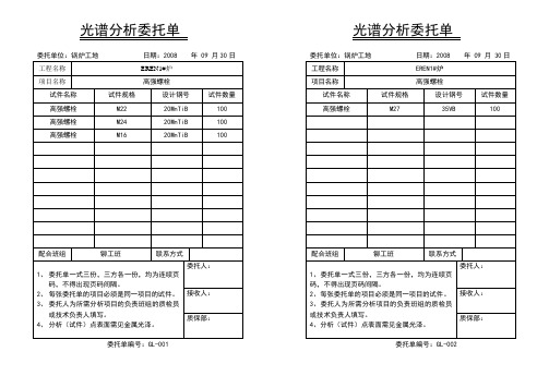
委托单位:锅炉工地日期:2008 年 09 月30日委托单编号:GL-001委托单位:锅炉工地日期:2008 年 09 月 30日委托单编号:GL-002委托单位:锅炉工地日期:2006 年 02 月 21日委托单编号:GL-003委托单位:锅炉工地日期:2006 年 02 月 21日委托单编号:GL-004委托单位:锅炉工地日期:2006 年 02 月 21日委托单编号:GL-005委托单位:锅炉工地日期:2006 年 02 月 21日委托单编号:GL-006委托单位:锅炉工地日期:2006 年 02 月 21日委托单编号:GL-007委托单位:锅炉工地日期:2006 年 02 月 21日委托单编号:GL-008光谱分析委托单委托单位:锅炉工地日期:2006 年 02 月 21日委托单编号:GL-009光谱分析委托单委托单编号:GL-028光谱分析委托单委托单编号:GL-029光谱分析委托单委托单编号:GL-030光谱分析委托单委托单编号:GL-031光谱分析委托单委托单编号:GL-032光谱分析委托单委托单编号:GL-033光谱分析委托单光谱分析委托单委托单位:锅炉工地日期:2006 年 03月 11日光谱分析委托单委托单编号:GL-050光谱分析委托单委托单编号:GL-051光谱分析委托单委托单位:锅炉工地 日期:2006 年 03月 11日 委托单编号:GL-052委托单位:锅炉工地 日期:2006 年 03月 11日委托单编号:GL-053委托单位:锅炉工地 日期:2006 年 02月 19日委托单编号:GL-054委托单位:锅炉工地日期:2006 年03月16日委托单编号:GL-055委托单位:锅炉工地日期:2006 年03月16日委托单编号:GL-056委托单位:锅炉工地 日期:2006 年03月17日委托单编号:GL-057委托单位:锅炉工地 日期:2006 年03月18日委托单编号:GL-058委托单位:锅炉工地日期:2006 年03月23日委托单编号:GL-059委托单位:锅炉工地日期:2006 年03月24日委托单编号:GL-060委托单位:锅炉工地日期:2006 年03月23日委托单编号:GL-061委托单位:锅炉工地日期:2006 年03月24日委托单编号:GL-062委托单位:锅炉工地日期:2006 年04月01日委托单编号:GL-063委托单位:锅炉工地日期:2006 年04月02日委托单编号:GL-064委托单位:锅炉工地日期:2006 年04月10日委托单编号:GL-065委托单位:锅炉工地日期:2006 年04月11日委托单编号:GL-066委托单位:锅炉工地日期:2006 年04月13日委托单编号:GL-067委托单位:锅炉工地日期:2006 年04月15日委托单编号:GL-068委托单位:锅炉工地日期:2006 年04月13日委托单编号:GL-069委托单位:锅炉工地日期:2006 年04月15日委托单编号:GL-070委托单位:锅炉工地日期:2006 年04月15日委托单编号:GL-071委托单位:锅炉工地日期:2006 年04月15日委托单编号:GL-072委托单位:锅炉工地日期:2006 年05月4日委托单编号:GL-073委托单位:锅炉工地日期:2006 年5月4日委托单编号:GL-074委托单位:锅炉工地日期:2006 年05月4日委托单编号:GL-075委托单位:锅炉工地日期:2006 年05月4日委托单编号:GL-076委托单位:锅炉工地日期:2006 年05月4日委托单编号:GL-077委托单位:锅炉工地日期:2006 年05月4日委托单编号:GL-078委托单位:锅炉工地 日期:2006 年05月4日委托单编号:GL-079委托单位:锅炉工地 日期:2006 年05月4日 委托单编号:GL-080委托单位:锅炉工地日期:2006 年05月4日委托单编号:GL-081委托单位:锅炉工地日期:2006 年04月25日委托单编号:GL-082委托单位:锅炉工地日期:2006 年04月25日委托单编号:GL-083委托单位:锅炉工地日期:2006 年04月25日委托单编号:GL-084委托单位:锅炉工地日期:2006 年04月25日委托单编号:GL-085委托单位:锅炉工地日期:2006 年04月25日委托单编号:GL-086委托单位:锅炉工地日期:2006 年03月25日委托单位:锅炉工地日期:2006 年04月25日委托单位:锅炉工地日期:2006 年03月25日委托单位:锅炉工地日期:2006 年03月25日委托单位:锅炉工地日期:2006 年04月25日委托单位:锅炉工地日期:2006 年04月25日委托单位:锅炉工地日期:2006 年04月25日委托单位:锅炉工地日期:2006 年04月25日委托单位:锅炉工地日期:2006 年04月25日委托单位:锅炉工地日期:2006 年04月25日委托单位:锅炉工地日期:2006 年04月25日委托单位:锅炉工地日期:2006 年04月25日委托单位:锅炉工地日期:2006 年04月25日委托单位:锅炉工地日期:2006 年04月25日。
第三章_第二节_TRIBON M1舾装设备的编码

第二节 Tribon M1舾装设备的编码设备、部件、管系、电缆、通风以及铁舾装件是舾装生产数字化设计中重要组成部分。
通过向设计完成的船体数字空间中调用设备及铁舾件,按设计规范进行布置,再通过在同一场景下按系统设计和规范要求进行管、风、电的布放,完成船舶舾装的数字化放样设计。
但是,几何元素的布置并不能满足企业对于生产信息提取、组织、集配的需要。
在大的空间中设备和各种舾装件的布置许多是基于约束条件或基于特征映射的装配过程。
上述这些信息,必须通过信息处理器加以整理,进入Tribon 系统。
Tribon 系统为用户提供了Components 信息处理器,它通过编码的形式,由用户将各类相关的信息加以整理输入到计算机中供系统和用户的查询、调用,使数字化设计的虚拟船舶成为具有PIM(Product Information Model)的产品信息模型。
一、 C omponents 的调用和生成在Windows 下点取:开始→程序→Tribon M1→Outfitting →Components →如图3-10。
图3-10 Tribon 系统Components 界面 图3-11 按专业划分的附件的目录树在文件管理器中包含了管子、设备、电器、风道、舱室、机座、电缆,支架、绝缘、固定支架、家具、梯子、构件、其它等,如图3-11。
(一) 部件的制作用鼠标点取Pipe 将出现管部件的子项,再用鼠标选取其下General Piping Comp 项,然后,点取鼠标的右键,选取New ,出现用户定义类型码对话框,如图3-12。
输入定义的类型码的后三位,系统将进入部件参数对话框,如图3-13。
输入部件的分组号,材料号,部件名称,系统将进入部件编写器表格界面,如图3-14。
部件编写器表格包含“一般信心、管子几何定义信息、管子连接几何约束定义信息、P&ID 符号定义信息、投影图形参数信息、安装范围和重心参数信息、相关部件信息、用户自定义信息”等,用户逐一按表格提供的管理项目填入正确的数据,就可以形成对应的部件,并保存在数据库中,供系统装配数字化船舶和整理托盘时调用。
C#和C++的速度大比拼

一。一般这种差别可以忽略不计。
int main(int argc, char* argv[]) {
if (argc != 2) {
std::cerr << "Usage:\tdb [rows]\n"; return 1; };
::CoInitialize(NULL); int NUM = atoi(argv[1]); DWORD dw = ::GetTickCount(); _ConnectionPtr conptr(__uuidof(Connection));
当今应用程序服务器往往都要用到数据库,所以我觉得用 来测试 C#的数据库存 取性能与用常规 ADO 测试 Visual C++的数据库存取性能进行比较是很能说明问题的一个好方 法。 XML 测试
XML 是一种最新的并且是流行的技术。因此许多人都会对用 C# 和 Visual C++解析 XML 的性能感兴趣。
Visual C++是 Win32 平台上性能最好的编译器之一,我想这已经成为一种共识。.NET 是 微软提供的一种新的应用平台。
首先我说明一下自己机器的软硬件环境: 硬件环境:Dell Inspiron 3800 G700GT 笔记本电脑 CPU/PIII/700,ROM/128MB, HD/12GB。 软件环境:Windows 2000 + SP2,.NET 平台 + Visual ,Office XP。 所有的测试均是在命令行状态下以 RELEASE 模式编译程序,而非 Visual Studio IDE 集成开 发环境,并在命令行状态下执行程序。没有对编译过程进行任何优化。 本 文 的 测 试 由 四 个 部 分 组 成 。 其 中 包 括 用 著 名 的 埃 拉 托 色 尼 过 滤 算 法 ( Sieves of Eratosthenes)进行的测试及其它的单项测试,单项测试主要的考察.NET 框架中特定项目的 性能:
MIL-STD-1916s

▪ SPC与持续改善等必需训练之记录:例如训练课程 之时数与内容;品质计划中律定各层级需接受之 个别训练课程;讲师之资格评定;管理阶层参与 训练之证明等。
▪ 明订各部门涉及SPC与品质改进之权责与编组运作
品质系统施行与有效性之要求
▪ 使用管制图时,设定合理样本数与抽样频率 之理由;决定管制界限或修正界限之程序书; 超出管制界限之判定准则。
▪ 1.代字表; ▪ 2.计数型抽样表; ▪ 3.计量型抽样表; ▪ 4.连续型抽样表,共四种表。
分别满足计数值、计量值及连续生产型之抽样 方式。除去105E之双次、多次抽样,均为单次 抽样。
判定标准不以AQL百分不良率为允收水准,是 「0收1退」不含任何不良之允收。
使用要求事项
MIL-STD-1916抽样表特别声明:
品质系统施行与有效性之要求
列举制程改善之证据:
▪ 制造流程图上标示管制点,在该点位置配有防止 不合格制造之动作。
▪ 使用制程改善技术与工具之证据,例如:PDCA管 理循环、FMEA失效模式与效应分析、柏拉图分 析、要因分析等。
▪ 评量之工具,例如:趋势分析、品质成本、减少 周期循环及不良率、六标准差之制程能力等。
▪ 使用各种制程改善工具之成果 ▪ 借重实验计划,以降低制程机遇原因之变异,改
善生产力之成果。
品质系统施行与有效性之要求
ቤተ መጻሕፍቲ ባይዱ 列举制程管制之证据:
▪ 制程管制技术之使用,例如:SPC统计制程管制、 自动化、量具管理、预防保养、目视检验等。
▪ 制程管制计划,包括:SPC之各项改进目标,及管 理阶层之承诺声明。
一般要求
为核准【替代允收方法】,合约中应包含评鉴 计划,以便于定期查证制程稳定性、制程能力 以及在【替代允收方法】发展时的其它情况。 制程能力最低要求为
- 1、下载文档前请自行甄别文档内容的完整性,平台不提供额外的编辑、内容补充、找答案等附加服务。
- 2、"仅部分预览"的文档,不可在线预览部分如存在完整性等问题,可反馈申请退款(可完整预览的文档不适用该条件!)。
- 3、如文档侵犯您的权益,请联系客服反馈,我们会尽快为您处理(人工客服工作时间:9:00-18:30)。
中国工程建设标准化协会标准钢制电缆桥架工程设计规范主编单位中国工程建设标准化协会电气工程委员会批准单位中国工程建渗标准化协会批准日期年月日前言电缆桥架技术是我国化工轻工等部门在年代和改变了过给全塑型塑料电缆密集的电缆回路布线对电缆线路的并带来特别是近年来国内专业性或目前已有上百个厂中国工程建设标准化协会电气委员会电缆反复征求有关现批准并推请将意见及有关资料寄交北京良乡中国工程建设标准化协会电气委员会中国工程建设标准化协会年月日目次第一章总则第二章桥架第一节结构类型及品种第二节型号及规格第三节技术要求第四节试验第五节检验第六节标志贮存第三章桥架工程设计第一节桥架型式及品种选择第二节梯架规格选择第三节荷载等级选择第四节表面防腐处理方式选择第五节吊架配置第六节防火第七节接地第八节桥架系统设计内容附录一桥架结构强度的计算方法附录二桥架荷载试验附录三热浸镀锌附着量试验方法附录四热浸镀锌层均匀性试验方法附录五热浸镀锌层附着性锤击试验方法附录六接头导电性试验附录七环境条件等级附录八本规范用词说明附加说明第一章总则第条钢制电缆桥架制造必须贯彻执行国家有关技术方针政策应做到技安全适用第条试验和第条桥架产品应经国家的桥架专业质量检测机构检第条除应按照本规范执第二章桥架第一节结构类型及品种第条附件以用以支承电缆的具有连续的刚性结构系统的第条桥架可包含下列结构类型有孔托盘无孔托盘是由底板与侧边构成的或由整块钢板弯制成梯架组装式托盘是由适于工程现场任意组合的有孔部件用第条桥架可包含下列结构品种直线段是指一段不能改变方向或尺寸的用于直接承托电弯通是指一段能改变方向或尺寸的用于直接承托电缆的可包含下列品种水平弯通分梯架的部件分变宽两种水平四通在同一水平面以梯架的部件变宽两种分分梯架的部件变宽两种梯架的部件变宽两种变径直通梯第条直线段与弯通之间的连接以构成连续性刚性的桥架系统所必需的连接固定或补直线连接板铰链连接板连续铰连板变宽连接板变高连接板伸缩连接板转弯连接板上下连接板分隔板紧第条可托臂分立柱异吊架悬吊托盘梯架的刚性部件异型钢其它固定支架第二节型号及规格条防腐层类别名称规托梯架的直线段和弯通依次标明宽吊架标明一个或几个主要技术特性的尺荷载等级防腐层类别涂漆或烤漆电镀锌喷涂粉末热浸镀锌电镀锌后喷涂粉末热镀锌后涂漆其它其中可用文第条梯架的宽度与高度常用规格尺寸系列可见表条梯架常用规格表注符号第条梯架弯通常用的内侧弯曲半径如下为第条不宜大于底部总面积的第条直线段梯架横档中心间距和梯架弯通横档长度处的中心间距均为横档宽度为条条第三节技术要求第条在满足强度要求的条件下其材质应符合钢并符合普通碳素钢标第条梯架允许最小板材厚度可见表梯架允许最小板材厚度表第条表面防腐层材料应符合国家现行有关标准的规第条标宜用第条普通螺栓材质应符合钢铆钉等紧固件材料应符合第条吊架跨距为按简支梁的条件下梯架的额定均布荷载分为四级详见表托盘梯架的荷载等级表第条刚第条应按第条荷载试验的使桥架最初产生永久变形时的荷载除以安全系数第条梯架相应第条梯托臂等本体结构强度相第条梯架的不同跨距与允许均布荷载的关系条梯架在承受额定均布荷载时的相对挠度不应大于条不应大于条梯架在不第条应符合第第条应符合表热浸镀锌技术质量指标第条电镀锌防腐处理的技术质应符合表和表电镀锌技术质量指标第条应符合表和表喷涂粉末技术质量指标第条应符合表和表的涂漆技术质量指标第条镀锌后再喷涂粉末或涂漆的复合防腐处理的其应符合表涂漆层应分别符合表及表第条对镀锌镍合金高钝化等其它防腐处理的桥应按第并应具有明确的技术质量指条料的机械性能不得有漏焊弧坑等缺陷并应达到标第条梯架几何尺寸极限偏差长度级宽度不得大于级高度不得大于第条螺栓孔径与孔距的允许偏差螺栓孔径可比螺杆公称直径大或螺栓孔精度不应低螺栓连接孔的孔距同一组内相邻两孔间同一组内任意两孔间橡邻两组的端孔间第条应按第不得大于第四节试验第条荷载试验第条防腐层人工环境试验可按表人工环境试验项目及周期表周期其余按为周期第条应符合下列要求厚度按附录三重量法或按覆盖层厚度测量覆盖层厚度测量附着力除板厚大于的按附录五锤击法测定其余都按标准规定的划格法测三第条涂层性能试验应符合下列要求厚度按或上非磁性覆盖层厚度测量附着力柔韧性冲击强度耐标准的规第条梯架连接电阻测试应按附录六的规第五节检验第条产品出厂应检验项目为外观质量尺寸精度防腐层厚度及附着力焊接表面质量热浸锌层均匀性第条正式生产后工艺有较大改变产品停产国家质量检测机构或认证组织要求对该产品进行型式检第条四节有关检第条产品抽样及判定样本应为随机抽样抽检数量为每批产品的但不宜少于件允许荷载试验样本仅取每批产品样本中有可抽取同批产品第二样本进行检验防腐层质量可允许直接对产品或对同一材料相同工艺第六节贮存第条梯架的直线段宜按单位长度计价第条其内容可包含第条产品名称出厂日期工程项第条标志应清条产品包装应能防止在运输过程中受到机械损并应根据运输方式及部件规格如包装箱宜便于吊装搬也可按用户要求采取分类或工程区第条产品合格证书及出第条应避免受到含第条桥架各部件宜分类堆放层间要有适当软垫物第三章桥架工程设计第一节桥架型式及品种选择第条或有防护外部影应选用有盖无第条宜选用组装式托第条除第可用有孔型第条选用第应满足第条至第第条第条在公共通底层梯架上宜第条低压动力电缆与控制电缆共用同一托盘或梯架相互间宜设置隔板梯架分支引下处宜有适当的弯通因受空间条件限制不便装设弯通或有特殊要求时可选用软接板铰接板连接两段不同宽度第条吊架应按工程布置条件第二节梯架规格选择第条应按下列要求选择动力电缆可取控制电缆可取且宜预留应符合第第工作均布荷载下的相对挠度不宜大于第条可按单件标准长度条第条第三节荷载等级选择第条工作均布荷载不应大于所选荷载等级的额定均吊架的实际跨距不等于则工作均布荷载应满足式中第条工作均布荷载的确定工安装或检修可能有工作均布荷载按电附加集中荷载的等效均布值可由下列公式换算式中可按第条第条对跨距大于户外风雪作用等特殊荷载的应按工稳定性的计算或试验验第四节表面防腐处理方式选择第条耐久性和技术经济性等因素第条一般情况宜按表选择适于工程环境条件第五节吊架配置第条应满足第第条吊架配置一当半径不大于应在距非直线段与直线段接合处的直线段侧设置一个支当半径大于时在非直第条梯架层间距离以及配置层数要当需采用与本标准第应指第条梯架直线段每隔应预留伸缩缝表表面防腐处理方式选择注符号表示推荐防腐类别第六节防火第条梯架添加具并在桥架表面涂刷符合的防火涂层等措施其整体耐火性还应符合国第七节接地第条条应符合下列要求梯架端部之间连接电阻不应大于接地第条每段条对于振动场所在接地部位的连接处应装置弹第八节桥架系统设计内容第条桥架系统工程设计应与建筑结构工艺以及有关专业密切配吊架规格附录一桥架结构强度的计算方法梯架的强度计算如附图所示弯矩如附图所示其表达式为式中作用在托盘梯架结构的最大弯曲正应力式中可取梯架横截面形心如附图所示满足托盘梯架强度要求的条件是式中即为材料的屈服极限除以安全系数对钢取梯架按简支梁计算跨中最大挠度为式中在侧边上翼宽度远远小于跨距值托梯架稳定性临界均布荷载值的近似公式LMmaxq(a)(b)YmaxO附图托盘梯架荷载及弯矩图附图托盘梯架横截面式中整板折弯托盘侧边形心到翻边中面的距离如附图梯架侧边或非整板折弯托盘拆边形心到翻边中面的距离如附图支承条件和初曲率等影响因素引起的修正系数其值取稳定性许用均布荷载值为式中建议取(a)(b)Mmax(a)(b)附图梯架侧边或整板折弯侧边截面附图梯架中横档荷载及弯矩图梯架的横档强度计算在中间如附图其弯矩如附图最大弯矩在跨中其值为式中横档的最大弯曲应力应满足式中如附图托臂的强度计算梯X附图托臂横截面附图托盘梯架作用于托臂的总支承力如附图其弯矩如附图式中按两跨超静定梁时如附图所示值为式中作用在托盘梯架上的额定均布荷载最大弯曲应力应满足式中到最远点的垂直如附如附图最大弯曲应力应满足式中该坐标系的坐标原点必须立柱结构如附图所示在强度计算时将它看成压弯杆或其最大应力为式中梯架对称轴到立柱形心轴之间的距离为满足压弯构件的刚度和稳定性要求立柱的长细比还应符合下列关系附图立柱结构附图受拉螺栓群式中受剪螺栓连接的强度计算螺栓群配置方式如附图各螺栓均匀受剪力为式中每个螺栓的受力方向是垂直于螺栓与螺栓群中心根据这一假设可以导出下列关系式由于力所承受的轴方向的分力螺栓由于力所承受的轴方向螺栓群中心的距离在受剪螺栓满足强度的条件为式中螺栓的容许剪应力钢制成的螺栓取式中由螺栓挤压所决定的抗挤压能力钢制成的螺栓取当当受拉螺拉连接的强度计算作用下的强度计算作如下假设对接面绕即按附图根据以上基本假设式中螺栓坐标受拉螺栓满足强度的条件为式中式中材料的容许拉应力钢取注若承载能力的计算值大于按本标准附录二试验验证确定的值应以后者为准附录二桥架荷载试验横档或底板与侧边的连接或任何部件的外形不同对每一种结构的托盘支承型式与跨距梯架两端及两侧不受任何约支承跨距按款支架如附图圆钢焊接在底座附图试验用支架形钢条开有深试样定位字形钢条支撑两个圆钢荷载材料钢条可用厚宽长度不大于其它荷载材料宽度不大于长度不大于最大重量不超过允许用厚长度不大于的荷载材料之间及荷载与拆边距离均为加载至少分允许均布荷载的确定在试样上逐步加载直至使梁的跨度中点产生跨距的或者当翻边或侧边出现绉折现象时的均布荷载除以安全系数布荷不宜超过额定荷载的梯架的挠度测量量具精度不低于测点位于跨距中每次加载后即为该荷载下的挠度值荷载特性及挠度曲线的建立应根据不少于种跨距长度跨距宜从可按间隔可将款吊架试验对每种型规格的支吊架吊吊架固定体及试样定位参见附图附图附图所示附图吊架固定体及定位方式吊架固定体吊架或立柱式中系数取吊架相邻两侧等跨布置时的跨距梯架的额定均布荷载梯架及盖板附件自重取按托盘荷载可吊试验时不应少于次加载以各层托臂同时承受各自测量与检查每次加载后处的位移或变形量量具精度不低于卡接式托臂附录三热浸镀锌附着量试验方法试件准备材料规格产品形状等选取有代表性的应与产品在同一工艺条件下镀将镀锌后的试样两端各切去三段试样附着量的平均值每段测试面积不应小于脱层溶液配制溶解三氧化锑或三氯化二锑于比重的浓盐酸中用蒸馏水稀释至试验方法试样用四清除表面油污然后以流净布擦干再以乙醇洗净称量段试样估计锌层重量的按试样表面每平方厘米不少于将称量后的试样放入脱层液中直至锌层完全溶解用以称重后测量试样的表面积附着量计算式中镀锌层近似厚度式中取值为附录四热浸镀锌层均匀性试验方法试样准备应与产品在同一工艺条件下镀在试样上切取长如试样过大钢板试样尺寸为以净布擦干后再浸入比重的硫酸以将试样两端露出基硫酸铜溶液配制方法化学纯硫酸铜溶于加热溶解后冷却至室温加入氢氧化铜或碳酸铜溶液加入静止以上然后过滤或吸出上面该溶液在比重应为否则应以浓硫酸铜溶液试验准备容器应使硫酸铜溶又能使试样与容器壁保持不小于硫酸铜溶液的数量按被试面积每不小于四试验方法置于此时不许搅动溶液亦不得移动试样以流水每次配制的硫酸铜溶液可浸蚀经上述试验后试样上出现红色的金属铜时为试样达到浸如铜的下边仍有金下列情形不作为浸蚀终点试样端部镀锌后划伤附录五热浸镀锌层附着性锤击试验方法锤击试验装置试验面应保持与锤锤击试验装置如附图试验规则试件应置于水平锤头面向台架中心锤柄与底座平面垂直以的间隔平行打击打击点离端部以外打击处不得同时打击附图锤击试验装置注号钢锤刃硬度肖氏锤柄用橡木底座钢板厚长附录六接头导电性试验试样每个试样应包括两个长度为的侧边及连接板或连接试验方法用的直流电流通过试样在接头两边相距处的两个点上测量电压降由测量得到的电压降与通过试样的电流计附录七环境条件等级气候环境条件等级见附表化学活性物质环境条件等级见附表当缺乏化学活性物质的定量释放数据时可按附表来划分气候环境条件等级附表化学活性物质环境条件等级附表续附表属于该等级平均值是长期数值的平均最大值是在每天不超过期间的极限值或峰值如超过则应提高等级盐雾条件只作定性规定的数值换算而来附表腐蚀环境划分的参考依据附录八本规范用词说明同的用词说明如下正面词采用反面词采用正面词采用反面词采用或样作的用词正面词采用反面词采用执行或非必须按照所指定的标准和规范执行的写法为附加说明和主要起草人名单主编单位中国工程建设标准化协会电气委员会参加单位中国建筑西南设计院能源部华东列车电站基地能源部西南电力设计院能源部华东电力渗计院能源部华北电力渗计院刘培仁李熙谋陈茹会李树平。
