7219中文资料
MAX7219
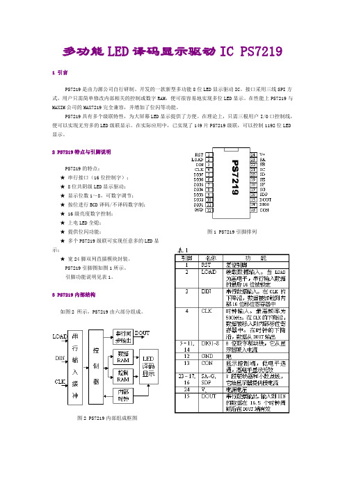
多功能LED译码显示驱动IC PS7219 1 引言PS7219是由力源公司自行研制、开发的一款新型多功能8位LED显示驱动IC。
接口采用三线SPI方式,用户只需简单修改内部相关的控制或数字RAM,便可很容易地实现多位LED显示。
在性能上PS7219与MAXIM 公司的MAX7219完全兼容,并增加了位闪等功能。
PS7219具有多个级联特性,为大屏幕LED显示提供了方便。
在理论上,只需三根用户I/O口控制线,便可以实现无穷多的LED级联显示。
在实际应用中,已实现了149片PS7219级联,可以控制1192位LED 显示。
2 PS7219特点与引脚说明PS7219的特点:★ 串行接口(16位控制字);★ 8位共阴级LED显示驱动;★ 显示位数1~8,可数字调节;★ 按位进行BCD译码/不译码数字制;★ 16级亮度数字控制;★ 上电LED全熄;★ 提供位闪功能;★ 多个PS7219级联可实现任意多的LED显示;★ 宽24脚双列直插模块封装。
PS7219引脚图如图1所示。
引脚功能说明见表1。
3 PS7219内部结构如图2 所示,PS7219由六部分组成。
图2 PS7219内部组成框图图1 PS7219引脚排列3.1 串行输入缓冲部分主要功能是与外部控制信号接口,将控制命令串行读入,并进行串并转换,供控制器读取。
3.2 控制器是整个IC的核心部分。
它先将输入缓冲部分的控制字读入处理,根据其地址值送到相应的控制RAM或数字RAM,同时将数据送入串行同步输出部分,以便在下一个控制字输入周期,将其串行输出。
3.3 控制RAM数据RAM这两部分一起控制LED译码显示部分,实现不同功能及字符的显示。
控制RAM包括:空操作寄存器,译码模式控制寄存器,亮度控制寄存器,掉电控制寄存器,闪烁控制寄存器,测试控制寄存器和扫描界线寄存器。
数据RAM包括:数据1—8寄存器。
3.4 LED译码显示根据控制RAM和数据RAM的不同值,来实现相应的显示功能。
tlc1543—10位ADC中文资料
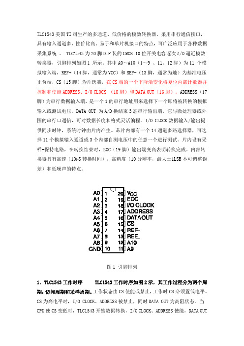
TLC1543美国TI司生产的多通道、低价格的模数转换器。
采用串行通信接口,具有输入通道多、性价比高、易于和单片机接口的特点,可广泛应用于各种数据采集系统。
TLC1543为20脚DIP装的CMOS 10位开关电容逐次A/D逼近模数转换器,引脚排列如图1 所示。
其中A0~A10(1~9 、11、12脚)为11 个模拟输入端,REF+(14脚,通常为VCC)和REF-(13脚,通常为地)为基准电压正负端,CS(15脚)为片选端,在CS端的一个下降沿变化将复位内部计数器并控制和使能ADDRESS、I/O CLOCK (18脚)和DATA OUT(16脚)。
ADDRESS(17脚)为串行数据输入端,是一个1的串行地址用来选择下一个即将被转换的模拟输入或测试电压。
DATA OUT 为A/D换结束3态串行输出端,它与微处理器或外围的串行口通信,可对数据长度和格式灵活编程。
I/O CLOCK数据输入/输出提供同步时钟,系统时钟由片内产生。
芯片内部有一个14通道多路选择器,可选择11个模拟输入通道或3个内部自测电压中的任意一个进行测试。
片内设有采样-保持电路,在转换结束时,EOC(19脚)输出端变高表明转换完成。
内部转换器具有高速(10µS转换时间),高精度(10分辨率,最大±1LSB不可调整误差)和低噪声的特点。
图1 引脚排列1.TLC1543工作时序TLC1543工作时序如图2示,其工作过程分为两个周期:访问周期和采样周期。
工作状态由CS使能或禁止,工作时CS必须置低电平。
CS 为高电平时,I/O CLOCK、ADDRESS被禁止,同时DATA OUT为高阻状态。
当CPU 使CS变低时,TLC1543开始数据转换,I/O CLOCK、ADDRESS使能,DATA OUT脱离高阻状态。
随后,CPU向ADDRESS提供4位通道地址,控制14个模拟通道选择器从11个外部模拟输入和3个内部自测电压中选通1 路送到采样保持电路。
947中文资料
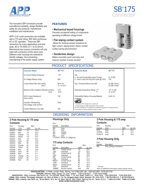
Anderson Power Products®HEADQUARTERS: 13 Pratts Junction Road, Sterling, MA 01564-2305 USA T:978-422-3600 F:978-422-3700EUROPE: Rathealy Road, Fermoy Co. Cork, Ireland T:353-(0)25-32277 F:353-(0)25-32296ASIA/PACIFIC: IDEAL Anderson Asia Pacific Ltd., Unit 922-928 Topsail Plaza, 11 On Sum Street, Shatin N.T., Hong Kong T:852-2636-0836 F:852-2635-9036CHINA: IDEAL Anderson T echnologies (Shenzhen) Ltd., Block A8 T antou W. Ind. Par, Songgang Baoan District, Shenzhen, PR. China 51810 T: 86-755-2768-2118 F: 86-755-2768-2218TAIWAN: IDEAL Anderson Asia Pacific Ltd., Taiwan Branch, 4F.-2, No.116, Dadun 20th St., Situn District, Taichung City 407, Taiwan (R.O.C.) T: 886-4-2310-6451 F:886-4-2310-6460SB ®175ConnectorPRODUCT SPECIFICATIONSThe innovative SB ® connectors provide cost-effective reliability, design flexibility and safety for your products' manufacture, installation and maintenance.APP's 2 & 3 pole connectors are availablewith a 175 amp rating, 600 Volts continuousAC or DC operation. There are SB ®connectors for many applications and wire sizes, #4 to 1/0 AWG (21.1 to 53.5mm²). Mechanical keys ensure connectors will only mate with connectors of the same color. Different color housings are selected to identify voltages, thus preventingmismatching of the power supply system.11111111116325G6 Gray #4 21.16326G6 Blue #4 21.16327G6 Orange #4 21.16328G6 Yellow #4 21.16329G6 Red #4 21.1111382 Individual 1/0 53.5947 Contact set (2) #2 33.61383 Individual #2 33.6948 Contact set (2) #4 21.11384 Individual #4 21.2948G 1* Contact set (2) #6 13.31348* Individual #6 13.3944G 1Contact set (2) #142.41347 Individual #1 42.4180BBS Bus bar contact N/A N/AFEATURES• Mechanical keyed housingsPrevents accidental mating of componentsoperating at different voltage levels • Flat wiping contact systemAllows for minimal contact resistance at high current, wiping action cleans contact surface during disconnection• Genderless designMakes assembly quick and easy and reduces number of parts stocked11* Thin wallNote: For additional colors please contact customer serviceAnderson Power Products®HEADQUARTERS: 13 Pratts Junction Road, Sterling, MA 01564-2305 USA T:978-422-3600 F:978-422-3700EUROPE: Rathealy Road, Fermoy Co. Cork, Ireland T:353-(0)25-32277 F:353-(0)25-32296ASIA/PACIFIC: IDEAL Anderson Asia Pacific Ltd., Unit 922-928 Topsail Plaza, 11 On Sum Street, Shatin N.T., Hong Kong T:852-2636-0836 F:852-2635-9036CHINA: IDEAL Anderson Technologies (Shenzhen) Ltd., Block A8 T antou W. Ind. Par, Songgang Baoan District, Shenzhen, PR. China 51810 T : 86-755-2768-2118 F: 86-755-2768-2218TAIWAN: IDEAL Anderson Asia Pacific Ltd., Taiwan Branch, 4F.-2, No.116, Dadun 20th St., Situn District, Taichung City 407, Taiwan (R.O.C.) T: 886-4-2310-6451 F:886-4-2310-6460SB ®175 ConnectorORDERING INFORMATION & DIMENSIONSTEMPERATURE RISE CHARTAccessoriesPartNumber Description 995G1 Handle, hardware & lock washers - Gray 995G3 Handle, hardware & lock washers - Red 923 Manual release, locking half with clamps and hardware 924 Manual release, mounting half with clamps and hardware110G56 Lock nut for use with Bus bar contact SB175-lockout Safety lockout 111197G1 Charger key 134G2 Dust cover945 Cable clamps 945G3 Cable clamps-2 single conductor with hardware. Use with "A" frame only.946G1 Cable clamps-1 twin conductor with hardware. Use with "A" frame only.BushingsPart WireNumber Description AWG sq. mm 5648 Use with 944 1/0 to #10 53.5 to 5.15663 Use with 944 1/0 to #6 53.5 to 13.35687 Use with 944 1/0 to #1 53.5 to 42.45690 Use with 944 1/0 to #2 53.5 to 33.65693Use with 944 1/0 to #4 53.5 to 21.2ToolingPartNumber Description 1368 Hand tool for 1/0 to #1 (53.5/42.4)1387G 1Pneumatic tool1388G3 - die for 1/0 to #1 (53.5/42.4)1388G5 - die for #41389G5 - locator for #41389G3 - locator for 1/0 to #1 (53.5/42.4)1303G4 - die for 1/0 to #4 (53.5/21.1)1304G4- locator for 1/0 to #4 (53.5/21.1)020*******800100012000.528321285122048SB175Pulse Current CapabilityDuration of Current (seconds)A m p e r e s01020304040801201602001/01 AWG 2 AWG 4 AWGSB175Temperature Rise at Constant CurrentAmperes AppliedT e m p e r a t u r e (°C)1/01 AWG 2 AWG 4 AWGContactsPart -A--B- -C- -D- Bus Bar LayoutPart - J - - K - - L- - M -Number mm in. mm in. mm in. mm in.180BBS26.8 1.05 26.8(min) 1.05(min) 9.53 0.375 3.43 0.135Mounting DimensionsHousingBus Bar Mounting TablePart - E - - F - Number mm in. mm in. 180BBS88.9 3.50 10.2 0.40Part - J -Number mm in.[53.1]2.09[25.4]1.0DS-SB175 REV05。
ps7219
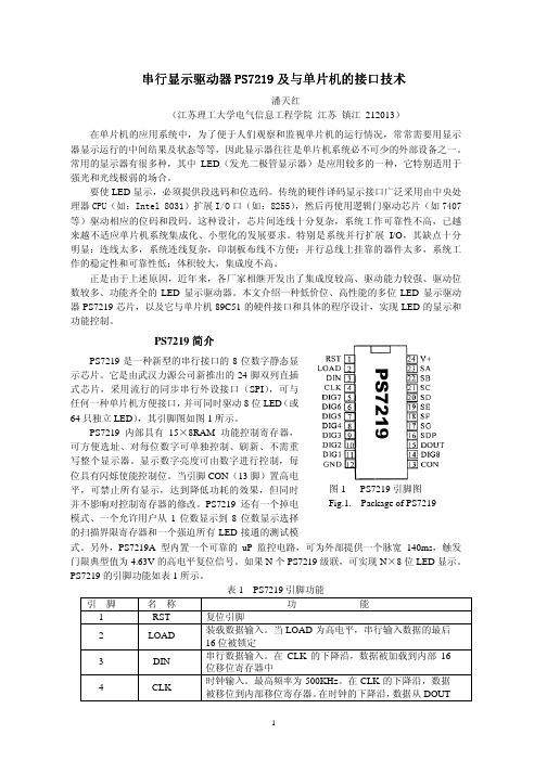
地址,地址编码如表 2 所示。D7~D0 为5个控制寄存器命令字或 8 个 LED 数码管待显示的
数据。因为控制寄存器与显示数据寄存器均独立编址,所以可以通过程序单独对每个寄存器
进行操作。一般情况下,程序先送控制命令,后向显示寄存器送数据,但必须注意,每 16 位
为一组,从高位地址字节最高位开始送起,直到低位数据字最后一位为止。
未用 测试控制
×
0
10 1
×5
×
0
11 0
×6
×
0
11 1
×7
×
1
00 0
×8
×
1
00 1
×9
×
1
01 0
×A
×
1
01 1
×B
×
1
10 0
×C
×
1
10 1
×D
×
1
11 0
×E
×
1
11 0
×F
PS7219 按 5 个控制寄存器规定的方式对待显示的数字自动扫描显示,所以有必要对各控 制寄存器的功能有所了解,现分述如下:
图 2 为 PS7219 工作时序图。由图 2 可知,DIN 是串行数据输入端,在 CLK 的上升沿,
一位数据被加载到内部 16 位移位寄存器中,CLK 端最高输入频率可达 500KHz,在输入时钟
信号的每个上升沿,均有1位数据由 DIN 移入到内部寄存器中,LOAD 用来装载数据,在 LOAD
的上升沿,16 位串行输入数据被锁存到数字或控制寄存器中。LOAD 必须在第 16 个时钟上
3
图 3 PS7219 和 89C51 的接口电路
实际上,数码管的位数可在 1~8 之间任意选择,这可由写入的扫描界线寄存器的命令字 决定。注意:为了使由峰值数字驱动器电流引起的纹波减到最小,需要在 V+和 GND 之间尽 可能靠近芯片的地方外接一个 10μF 的电解电容和一个 0.1μF 的瓷片电容。PS7219 应放在 紧靠 LED 显示器的地方,且连线尽可能短,两个 GND 引脚都必须连接到地线上。
2SC2879A中文资料
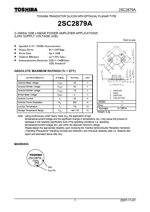
TOSHIBA TRANSISTOR SILICON NPN EPITAXIAL PLANAR TYPE2SC2879A2~30MHz SSB LINEAR POWER AMPLIFIER APPLICATIONS (LOW SUPPLY VOLTAGE USE)z Specified 12.5V, 28MHz Characteristics z Output Power : Po = 100W PEP z Power Gain : Gp = 13dB z Collector Efficiency: ηC = 35% (Min.)z Intermodulation Distortion : IMD = −24dB(Max.)(MIL Standard)ABSOLUTE MAXIMUM RATINGS (Tc = 25°C)CHARACTERISTIC SYMBOL RATING UNITCollector-Base Voltage V CBO 45 V Collector-Emitter Voltage V CES45 V Collector-Emitter Voltage V CEO 18 V Emitter-Base Voltage V EBO 4 V Collector CurrentI C 25 ACollector Power Dissipation P C 250 WJunction Temperature T j 175 °C Storage Temperature RangeT stg−65~175 °CNote: Using continuously under heavy loads (e.g. the application of hightemperature/current/voltage and the significant change in temperature, etc.) may cause this product to decrease in the reliability significantly even if the operating conditions (i.e. operating temperature/current/voltage, etc.) are within the absolute maximum ratings.Please design the appropriate reliability upon reviewing the Toshiba Semiconductor Reliability Handbook (“Handling Precautions”/“Derating Concept and Methods”) and individual reliability data (i.e. reliability test report and estimated failure rate, etc).MARKINGDot Lot No.JEDEC — EIAJ— TOSHIBA2–13B1AWeight: 5.2gUnit in mmELECTRICAL CHARACTERISTICS (Tc = 25°C)CHARACTERISTIC SYMBOL TEST CONDITION MIN. TYP. MAX.UNITCollector-Emitter Breakdown Voltage V (BR) CEO I C = 100mA, I B = 0 18 — — V Collector-Emitter Breakdown Voltage V (BR) CES I C = 100mA, V EB = 0 45 — — V Emitter-Base Breakdown Voltage V (BR) EBOI E = 1mA, I C = 0 4 — — V DC Current Gainh FE V CE = 5V, I C = 10A 10—150Collector Output Capacitance C obV CB = 12.5V, I E = 0f = 1MHz— 700 — pFPower Gain G p 13.0 15.2 — dBInput Power Pi — 6 10 W PEP Collector Efficiency ηC 35 — — % Intermodulation DistortionIMDV CC = 12.5V, f 1 = 28.000MHzf 2 = 28.001MHzI idle = 100mA Po = 100W PEP .(Fig.)— — −24dB Series Equivalent Input Impedance Z in — 1.45−j0.95 — ΩSeries Equivalent Output ImpedanceZ out V CC = 12.5V, f = 28MHzΔf = 1kHz, Po = 100W PEP — 1.45−j1.0— ΩFig. Pi TEST CIRCUITCAUTIONThese are only typical curves and devices are not necessarily guaranteed at these curves.RESTRICTIONS ON PRODUCT USE20070701-EN GENERAL •The information contained herein is subject to change without notice.•TOSHIBA is continually working to improve the quality and reliability of its products. Nevertheless, semiconductor devices in general can malfunction or fail due to their inherent electrical sensitivity and vulnerability to physical stress. It is the responsibility of the buyer, when utilizing TOSHIBA products, to comply with the standards of safety in making a safe design for the entire system, and to avoid situations in which a malfunction or failure of such TOSHIBA products could cause loss of human life, bodily injury or damage to property.In developing your designs, please ensure that TOSHIBA products are used within specified operating ranges as set forth in the most recent TOSHIBA products specifications. Also, please keep in mind the precautions and conditions set forth in the “Handling Guide for Semiconductor Devices,” or “TOSHIBA Semiconductor Reliability Handbook” etc.• The TOSHIBA products listed in this document are intended for usage in general electronics applications (computer, personal equipment, office equipment, measuring equipment, industrial robotics, domestic appliances, etc.).These TOSHIBA products are neither intended nor warranted for usage in equipment that requires extraordinarily high quality and/or reliability or a malfunction or failure of which may cause loss of human life or bodily injury (“Unintended Usage”). Unintended Usage include atomic energy control instruments, airplane or spaceship instruments, transportation instruments, traffic signal instruments, combustion control instruments, medical instruments, all types of safety devices, etc.. Unintended Usage of TOSHIBA products listed in his document shall be made at the customer’s own risk.•The products described in this document shall not be used or embedded to any downstream products of which manufacture, use and/or sale are prohibited under any applicable laws and regulations.• The information contained herein is presented only as a guide for the applications of our products. No responsibility is assumed by TOSHIBA for any infringements of patents or other rights of the third parties which may result from its use. No license is granted by implication or otherwise under any patents or other rights of TOSHIBA or the third parties.• Please contact your sales representative for product-by-product details in this document regarding RoHS compatibility. Please use these products in this document in compliance with all applicable laws and regulations that regulate the inclusion or use of controlled substances. Toshiba assumes no liability for damage or losses occurring as a result of noncompliance with applicable laws and regulations.。
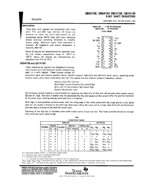
74199中文资料
元器件交易网IMPORTANT NOTICETexas Instruments and its subsidiaries (TI) reserve the right to make changes to their products or to discontinueany product or service without notice, and advise customers to obtain the latest version of relevant informationto verify, before placing orders, that information being relied on is current and complete. All products are soldsubject to the terms and conditions of sale supplied at the time of order acknowledgement, including thosepertaining to warranty, patent infringement, and limitation of liability.TI warrants performance of its semiconductor products to the specifications applicable at the time of sale inaccordance with TI’s standard warranty. Testing and other quality control techniques are utilized to the extentTI deems necessary to support this warranty. Specific testing of all parameters of each device is not necessarilyperformed, except those mandated by government requirements.CERTAIN APPLICATIONS USING SEMICONDUCTOR PRODUCTS MAY INVOLVE POTENTIAL RISKS OFDEATH, PERSONAL INJURY, OR SEVERE PROPERTY OR ENVIRONMENTAL DAMAGE (“CRITICALAPPLICATIONS”). TI SEMICONDUCTOR PRODUCTS ARE NOT DESIGNED, AUTHORIZED, ORWARRANTED TO BE SUITABLE FOR USE IN LIFE-SUPPORT DEVICES OR SYSTEMS OR OTHERCRITICAL APPLICATIONS. INCLUSION OF TI PRODUCTS IN SUCH APPLICATIONS IS UNDERSTOOD TOBE FULLY AT THE CUSTOMER’S RISK.In order to minimize risks associated with the customer’s applications, adequate design and operatingsafeguards must be provided by the customer to minimize inherent or procedural hazards.TI assumes no liability for applications assistance or customer product design. TI does not warrant or representthat any license, either express or implied, is granted under any patent right, copyright, mask work right, or otherintellectual property right of TI covering or relating to any combination, machine, or process in which suchsemiconductor products or services might be or are used. TI’s publication of information regarding any thirdparty’s products or services does not constitute TI’s approval, warranty or endorsement thereof.Copyright © 1998, Texas Instruments Incorporated。
BY721资料

Fig.4
Maximum permissible average forward current as a function of ambient temperature.
Fig.5
Maximum permissible average forward current as a function of ambient temperature.
Very fast high-voltage soft-recovery rectifiers
BY715 to BY724
SYMBOL IF(AV)
PARAMETER average forward current BY715 BY716 BY717 BY718 BY719 BY720 BY721 BY722 BY723 BY724
BY715 to BY724
MIN. − − − − − − − − − − − − − − − − − − − − − − − − − − − − − − 5 6
MAX.
UNIT kV kV kV kV kV kV kV kV kV kV kV kV kV kV kV kV kV kV kV kV kV kV kV kV kV kV kV kV kV kV
元器件交易网
Philips Semiconductors
Product specification
Very fast high-voltage soft-recovery rectifiers
FEATURES • Glass passivated • High maximum operating temperature • Low leakage current • Excellent stability • Soft-recovery switching characteristics • Compact construction. APPLICATIONS • For high-voltage rectification up to 75 kHz • High-voltage applications for: – Multipliers – Slot-wound diode-split-transformers.
JANTXV2N7219U中文资料

Note: Corresponding Spice and Saber models are available on the G&S Website. For footnotes refer to the last page
2
元器件交易网
IRFN240
—
Rise Time
—
Turn-Off Delay Time
—
Fall Time
—
Total Inductance
—
Ciss
Input Capacitance
—
Coss
Output Capacitance
—
Crss
Reverse Transfer Capacitance
—
Typ Max Units —— V 0.29 — V/°C
3
元器件交易网
IRFN240
Fig 5. Typical Capacitance Vs. Drain-to-Source Voltage
13a & b
Fig 6. Typical Gate Charge Vs. Gate-to-Source Voltage
Fig 7. Typical Source-Drain Diode Forward Voltage
5
元器件交易网
IRFN240
15V
VDS
L
D R IV E R
RG
210 V tp
D.U .T. IA S
0.01Ω
+ - VDD
A
Fig 12a. Unclamped Inductive Test Circuit
V (B R )D S S tp
max7219中文资料

max7219中文资料1、MAX7219介绍MAX7219是一种高集成化的串行输入/输出共阴极显示驱动器,可实现微处理器与7段码的接口,可以显示8位或64位单一LED。
芯片上包括BCD码译码器、多位扫描电路、段驱动器、位驱动器、内含8&TImes;8位静态RAM,用于存放显示数据。
只需外接一个电阻就可为所有的LED提供段电流。
MAX7219的三线串行接口适用于所有微处理器,单一位数据可被寻址和修正,无需重写整个显示器。
MAX7219具有软件译码和硬件译码两种功能,软件译码是根据各段笔划与数据位的对应关系进行编码,硬件译码采用BCD码(简称B码)译码。
MAX7219工作模式包括150μA低压电源关闭模式、模拟数字亮度控制、限扫寄存器(允许用户从第1位数字显示到第8位)及测试模式(点亮所有LED)。
2、MAX7219引脚功能MAX1279引脚排列如图1所示,图1 MAX1279引脚排列图引脚功能:DIN:串行数据输入端。
当CLK为上升沿时,数据存入内部的16位寄存器DOUT:串行数据输出端,用于级连扩展LOAD:装载数据输入,在装载的上升沿,串行输入的最后一个16位数据被锁存。
CLK:串行时钟输入,其最大工作频率可达10MHz。
时钟上升沿是数据输入,时钟下降时数据从串行数据输出口输出DIG0~DIG7:8位LED位选线,从共阴极LED中吸入电流SEGA~SEGGDP7段驱动和小数点驱动ISET:通过一个10k电阻和Vcc相连,设置段电流GND:地线V+:电源3、MAX7219的功能框图图2 MAX7219的功能框图串行输入数据在时钟上升沿时移入内部的16位移位寄存器,在装载的上升沿时数据被锁存在每一位或寄存器中。
装载信号必须在第16个时钟上升沿发生时或之后达到高电平,但要在下一个时钟的上升沿和数据丢失之前到达。
串行输入数据通过移位寄存器传输,在以后数据输出的16.5个时钟循环出现,数据在时钟的下降沿记录下来。
1911172资料
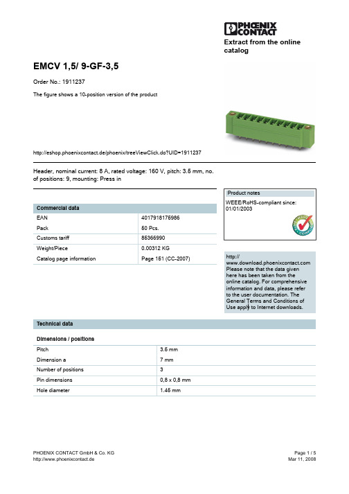
Extract from the onlinecatalogEMCV 1,5/ 9-GF-3,5Order No.: 1911237The figure shows a 10-position version of the producthttp://eshop.phoenixcontact.de/phoenix/treeViewClick.do?UID=1911237Header, nominal current: 8 A, rated voltage: 160 V, pitch: 3.5 mm, no. of positions: 9, mounting: Press inhttp://Please note that the data givenhere has been taken from theonline catalog. For comprehensiveinformation and data, please referto the user documentation. TheGeneral Terms and Conditions ofUse apply to Internet downloads. Technical dataDimensions / positionsPitch 3.5 mmDimension a7 mmNumber of positions3Pin dimensions0,8 x 0,8 mmHole diameter 1.45 mmTechnical dataInsulating material group IIIaRated surge voltage (III/3) 2.5 kVRated surge voltage (III/2) 2.5 kVRated surge voltage (II/2) 2.5 kVRated voltage (III/2)160 VRated voltage (II/2)250 VConnection in acc. with standard EN-VDENominal current I N8 ANominal voltage U N160 VMaximum load current8 AInsulating material PBTInflammability class acc. to UL 94V0Certificates / ApprovalsApproval logoCULNominal voltage U N300 VNominal current I N8 AULNominal voltage U N300 VNominal current I N8 ACertification CUL, GOST, ULAccessoriesItem Designation DescriptionAssembly1877258EMC 1,5-SH Stamp holder, for upper and lower stamp1877274EMCV 1,5-SS 1Stamp set, consisting of upper and lower stamp for 3.81 mm pitch,2 to 16-pos.Marking0804073SK 3,5/2,8:FORTL.ZAHLEN Marker card, printed horizontally, self-adhesive, 10-section markerstrip, 14 identical decades marked 1-10, 11-20 etc. up to 91-100,sufficient for 140 terminal blocksPlug/Adapter1734634CP-MSTB Coding profile, is inserted into the slot on the plug or invertedheader, red insulating materialAdditional productsItem Designation DescriptionGeneral1847068MC 1,5/ 3-STF-3,5Plug component, nominal current: 8 A, rated voltage: 160 V, pitch:3.5 mm, no. of positions: 3, type of connection: Screw connection 1863314MCVR 1,5/ 3-STF-3,5Plug component, nominal current: 8 A, rated voltage: 160 V, pitch:3.5 mm, no. of positions: 3, type of connection: Screw connection 1863013MCVW 1,5/ 3-STF-3,5Plug component, nominal current: 8 A, rated voltage: 160 V, pitch:3.5 mm, no. of positions: 3, type of connection: Screw connection DrawingsDrilling diagramDimensioned drawingAddressPHOENIX CONTACT GmbH & Co. KGFlachsmarktstr. 832825 Blomberg,GermanyPhone +49 5235 3 00Fax +49 5235 3 41200http://www.phoenixcontact.de© 2008 Phoenix ContactTechnical modifications reserved;。
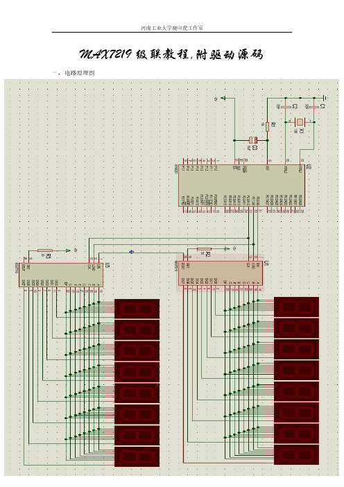
MAX7219级联教程
河南工业大学爬山虎工作室
DIN=1; else DIN=0; Dat <<= 1; CLK = 1; _nop_(); _nop_(); CLK = 0; } for(i=0;i<Num_Addr;i++) { for(j=0;j<16;j++) { CLK = 0; DIN = 0; CLK = 1; _nop_(); _nop_(); CLK = 0; } } LOAD = 1; } void Initialise7219()//初始化 { //第 0 个 7219 初始化 Write(0x00,0x09,0xff); //编码模式 Write(0x00,0x0b,0x07); //全部扫描 Write(0x00,0x0c,0x01); //正常模式:1,掉电模式:0 Write(0x00,0x0a,0x07); //消隐时间设为 T/2 //第 1 个 7219 初始化 Write(0x01,0x09,0xff); //编码模式 Write(0x01,0x0b,0x07); //全部扫描 Write(0x01,0x0c,0x01); //正常模式 Write(0x01,0x0a,0x07); //消隐时间设为 T/2 } void main() { u8 i; Initialise7219(); DelayMS(1); for(i=0;i<8;i++) {
河南工业大学爬山虎工作室
MAX7219 级联教程,附驱动源码
一、电路原理图
河南工业大学爬山虎工作室
二、 级联程序
#include <reg52.h> #include <intrins.h> #define u8 unsigned char #define uint unsigned int sbit DIN = P2^0; sbit LOAD = P2^1; sbit CLK = P2^2; u8 Disp_Buffer[8]={2,0,0,9,10,8,10,9}; //软件延时函数,延时 xms void DelayMS(uint x) { u8 t; while(x--) { for(t=120;t>0;t--); } } //向第 Num_Addr 片 7219 的 Addr 寄存器写入一个 Dat 数据 //Num_Addr:7219 地址(0~255) //Addr:7219 数显寄存器地址(1~8) //Dat:要显示的数据(0~15)(含字母) void Write(u8 Num_Addr,u8 Addr,u8 Dat) { u8 i,j; LOAD = 0; for(i=0;i<8;i++) { CLK = 0; if(Addr&0x80) DIN=1; else DIN=0; Addr <<= 1; CLK = 1; _nop_(); _nop_(); CLK = 0; } for(i=0;i<8;i++) { CLK = 0; if(Dat&0x80)
7219芯片资料

X 54 205
,一
小 Pl P12 P13 P14 PIS 川
遥 透 睡
等等来定义
由于 P7 1 29的 S
翻
P 21 57 9 2 -, 1通 15 ]6 1, 15 1, 110 1朴 1佗
朴
Rsl 咖 DIN 盯 叫 耀 沁归 呻 呻 圳即 仲心 哪 即 ,, , , : 5^
叹
匕 片 嚷
一 可禁止所有显示. 达到降低功耗的效果, 但同时并不影响对控 一 制寄存器的修改 P7 9 S 2 还有一个掉电模式, 1 一个允许用户从 一 位数显示到 8 1 位数显小选择的扫描界限寄存器和 个强迫 所有 E LD接通的测试模式. 另外 P71A型内置一个可靠的 S 29 林 P监控电路 可为外部提供一个脉宽 1 m , 0 45 触发门限典型值 为43 6V的高电平复位信号.如果 N 171 级联, . 个 七2 9 可实现 I x 位Lo N s E 显示_ 29 脚功能如表 1 巧71 的引 所示. 1 图2 为巧7 9 1 2 工作时序图 由图2 可知, N是串行数据 I D
动器 本文介绍一种低价位, 高性能的多位 庄D显示驱动器
宝 I,电 电粗出〔 人t_ 的 斟在晒' 七 ) f串撅压 箱 一川, 数 _ 个 v 行致 , ( 气 ) I 据 ) 1
一 时钟周期后在 n 1 l ) ( 襄有效
CL K
仁 OAO
件7 9 1 2 芯片,以及它与单片机8c 的硬件接口和具体的程 9 5 1
}平6 T 3
a - 0H 欣据或随址)-A z t .〔 8 "
PI ( 5 Ld4 D)叫」
() 5 显示测试寄存器: 其中D 一 1 7 D 位可任意; O 0 , D 二0
max7219使用详解
Max7219驱动程序一般的MCU因IO脚驱动能力不够,再加之MCU IO口资源有限,产品开发中通常是通过专门的驱动IC来驱动数码管。
7.1 学会看DatasheetMAX7219就是一款可以同时驱动8个数码管的IC。
下图是其引脚图及典型应用电路:我们的CPU只须三根线就可以控制MAX7219,这三根线是:DIN(第一脚),CS(第12脚),CLK(第13脚)。
DIN是数据输入脚,我们要显示的数据就是通过这根线发送到MAX7219的;CS是片选脚,MCU通过把该脚电平拉低来选中MAX7219,或者说MAX7219通过判断该引脚是否为低电平来使能该芯片。
CLK是时钟引脚,该时钟频率是MCU给到MAX7219的,MCU与7219之间的通信频率就根据该信号做基准。
7.2 MAX7219数据格式我们要让8个数码管显示"12345678",这个过程是怎么实现的呢?首先,要搞清楚MAX7219的数据格式,看图:MAX7219是以16位数据接收和发送的,也就是MCU传给MAX7219的数据必须是16位。
下面分析这16位数据格式:D15~D12为X:表示可以为任意值,因为这四位MAX7219目前还用不到。
D11~D8为ADDRESS:表示MAX7219的地址。
D7~D0为DATA,并且位7为高位(最先发送),位0位低位(最后发送)。
也就是当MCU向MAX7219发送一个16位数据时,其中的D11~D8表示选择MAX7219哪个地址,即数据D7~D0是送到该地址的。
7.3 地址译码MAX7219可以挂8个数码管,MCU是怎么把数据显示到指定的数码管的呢?这就要理解MAX7219的地址译码原理。
下图为MAX7219的地址映射图:D15~12以X表示,代表可为0,也可为1。
Digit0~7对应到8个数码管的地址。
Decode Mode:解码模式寄存器,其地址用16进制表示为0x09;Intensity:亮度调节寄存器,其地址用16进制表示为0x0A;Scan Limit:扫描范围寄存器,其地址用16进制表示为0x0B;Shutdown:省电模式,其地址用16进制表示为0x0C;Display Test:测试寄存器,其地址用16进制表示为0x0F;如果,我们要让第一个数码管显示,那么我们这里送到MAX7219的16位数据中的D11~8应该为0001。
