Actel_APB3总线使用
安美乐TCP(TC) 控制电源模块安全使用说明说明书

目 录 (01)关于说明书 (02)TCP(TC)控制电源模块安全使用说明 (02)涉及的其它说明书 (02)安全警示说明 (03)免责声明 (03)第一章产品说明 (04)1.1 产品简介 (04)1.2 设计及功能 (05)1.3 性能指标 (06)1.4 订货资料 (06)第二章安装连接 (07)2.1 TCP控制电源模块的安装连接 (07)2.1.1 连接TCP-100、TCP-240控制电源模块和TD驱动模块 (07)2.1.2 D15外控通讯接口 (07)2.1.3 连接供电电源 (08)2.1.4 安装环境要求 (08)2.2 TC-100控制模块的安装连接 (08)2.2.1 连接TC-100控制模块和TD驱动模块 (08)2.2.2 D15外控通讯接口 (09)2.2.3 安装环境要求 (09)第三章 操作方法 (10)3.1 TCP控制电源模块的操作方法 (10)3.1.1 连接TCP-100、TCP-240控制电源模块和TD驱动模块 (10)3.1.2 操作与显示 (10)3.2 TC-100控制模块的操作方法 (14)3.2.1 连接TC-100控制模块和TD驱动模块 (14)3.2.2 操作与显示 (14)第四章售后服务 (15)产品保修单 (16)关于说明书TCP(TC)控制电源模块安全使用说明在安装与使用TCP(TC)控制电源模块前,操作人员都应仔细阅读本说明书,并按照说明书中规定的条款安装与操作,以免造成人员伤害与设备损坏。
本说明书适用于TC-100控制模块、TCP-100和TCP-240控制电源模块及其后续改进型号。
因上述产品技术改进或说明书改版等原因导致的内容更新,本公司恕不另行通知,敬请谅解。
相关信息可登录中科科仪官方网站查询,网址:,或与本公司联系!本说明书版权及由本说明书引起、产生和包含的与“KYKY”相关知识产权归北京中科科仪股份有限公司所有,任何单位或个人未经授权不得擅自使用。
grlib说明文档中文版
5GRLIB design concept5.1introductionGRLIB是一个可重用IP Core的集合,并分成了多个VHDL库。
每一个库提供了特定厂商的元件或者一系列共享的功能或接口。
在GRLIB设计中使用的数据结构和元件声明都是通过库指定的VHDL包来输出的。
GRLIB是基于AMBA AHB和APB片上总线的,并把该总线用作标准的互联接口。
AHB/APB总线的实现是与AMBA-2.0相兼容的,并附加了额外的“sideband”(边带)信号。
这些边带信号的有三个用途:automatic address decoding,interrupt steering和device identification(a.k.a plug&play support)。
根据AHB/APB 信号的功能,GRLIB的库把这些信号以VHDL records的形式组合在一起。
GRLIB AMBA包的源文件在lib/grlib/amba/下。
所有的GRLIB core都使用同样的data structures来声明AMBA接口,这样相互之间的连接就很容易了。
GRLIB库还包含了一个AHB bus controller和一个AHB/APB bridge,借助这两个模块,可以很快组装成一个全功能的AHB/APB的系统。
下面的部分将描述AMBA总线是怎么实现的以及怎样用GRLIB来建一个SOC设计。
5.2AMAB AHB on-chip bus5.2.1General(概述)AMBA Advanced High-performance Bus(AHB)是一个multi-master的总线,可以以high data rate and/or variable latency的形式来互连各单元。
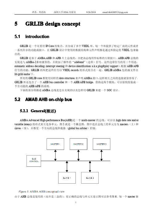
图5就是一个概念图。
图中连在总线上的单元分为masters(主)和slaves(客),并都受一个全局的总线仲裁器(global bus arbiter)控制。
jtagapb用法

jtagapb用法摘要:一、JTAGAPB简介1.JTAG简介2.JTAGAPB的作用二、JTAGAPB的连接方式1.硬件连接2.软件连接三、JTAGAPB的编程方法1.使用JTAGAPB工具进行编程2.使用编程器进行编程四、JTAGAPB的应用领域1.嵌入式系统开发2.物联网设备开发五、JTAGAPB的发展趋势1.在新技术中的运用2.未来发展方向正文:JTAGAPB是Joint Test Action Group-Advanced Package Bus的缩写,中文意为联合测试行动组-先进封装总线,它是一种用于芯片测试和编程的标准接口。
通过JTAGAPB,可以实现对芯片内部寄存器的访问和控制,从而对芯片进行测试和编程。
在嵌入式系统开发和物联网设备开发等领域中,JTAGAPB被广泛应用。
JTAGAPB的连接方式主要有硬件连接和软件连接两种。
硬件连接是通过JTAG测试接口将JTAGAPB与目标芯片连接起来,从而实现对芯片的访问。
软件连接则是通过在开发环境中配置JTAGAPB的相关参数,实现与目标芯片的通信。
在编程方面,可以使用JTAGAPB工具或编程器进行编程。
JTAGAPB工具通常提供了一个图形化的界面,方便用户进行编程操作。
编程器则需要用户通过命令行的方式进行编程。
无论使用哪种方法,都可以实现对目标芯片的编程。
随着科技的不断发展,JTAGAPB在新技术中的运用也越来越多。
例如,在物联网设备开发中,JTAGAPB可以用于对传感器节点进行编程和测试,从而提高开发效率。
此外,随着集成电路封装技术的进步,JTAGAPB也在不断发展和完善,以满足更高的技术要求。
总之,JTAGAPB作为一项成熟的技术,在嵌入式系统开发和物联网设备开发等领域具有广泛的应用前景。
AMBA_3_APB协议规范

AMBA_3_APB协议规范AMBA(高级微处理器总线)是一种用于系统级互连的开放标准协议,它由ARM公司开发,被广泛应用于嵌入式系统中。
AMBA_3_APB(高级微处理器总线第3代-高性能总线)是AMBA协议的一部分,它定义了一种高性能、低功耗的片内总线协议,用于连接处理器和外设。
1.信号:AMBA_3_APB协议规范定义了一系列信号,包括时钟信号、复位信号、总线控制信号、数据传输信号等。
时钟信号主要包括时钟线以及时钟使能信号,用于控制数据传输的时序。
复位信号用于重置外设以及总线控制器的状态。
总线控制信号用于控制总线的访问权限以及传输模式等。
数据传输信号用于在总线上传输数据。
2.传输:AMBA_3_APB协议规范定义了四种传输类型,分别是单个传输、设置传输、清除传输以及数据传输。
单个传输用于传输单个数据项,例如读取外设的寄存器值。
设置传输用于设置外设的寄存器值,例如写入配置信息。
清除传输用于清除外设的寄存器值,例如重置外设。
数据传输用于传输大量数据,例如读取或写入外设的缓冲区。
3.协议:AMBA_3_APB协议规范定义了一套协议,包括方法、地址空间、读写传输、保持传输、错误传输以及确认传输。
方法用于指示执行的操作类型,包括读、写等。
地址空间用于指定外设的寄存器地址。
读写传输用于实现读取或写入寄存器的操作。
保持传输用于在外设的寄存器繁忙时保持总线传输。
错误传输用于指示总线传输过程中的错误信息。
确认传输用于确认总线传输的完成。
4.时序:AMBA_3_APB协议规范定义了一套时序要求,包括时钟周期、数据有效性以及总线传输的顺序。
时钟周期用于控制数据传输的时序,包括时钟上升沿和下降沿的作用周期。
数据有效性用于指示数据在总线上的有效时间段,以及数据的采样时间。
总线传输的顺序用于指示多个传输之间的先后顺序,以及传输的优先级。
总结起来,AMBA_3_APB协议规范是一种用于连接处理器和外设的高性能、低功耗的片内总线协议。
Actel+FPGA的PWM+IP的应用

脉冲宽度调制(PWM)是英文“Pluse Width Modulation”的缩写,简称脉宽调制。
它是利用微处理器的数字输出来对模拟电路进行控制的一种非常有效的技术,根据相应的载荷的变化来调制晶体管栅极或基极的偏置,来实现开关稳压电源输出晶体管或晶体管导通时间的改变。
这种方式能使电源的输出电压在工作条件变化时保持恒定,广泛应用于测量、通信、功率控制与变化等许多领域。
Actel公司免费提供PWM IP核:Core PWM。
Core PWM是基于APB总线形式的,它的优点是可以连接到Core8051或者是CortexM1处理器上,方便用户进行SoC设计,本文将主要介绍Core PWM的原理与应用。
1. Core PWM介绍(1) PWM的控制方法采样控制理论中有一个重要结论:量相等而形状不同的窄脉冲加在具有惯性的环节上时,效果基本相同。
PWM控制技术就是以该结论为理论基础,对半导体开关器件的导通和关断进行控制,使输出端得到一系列幅值相等而宽度不相等的脉冲,用这些脉冲来代替正弦波或其他所需要的波形。
按一定的规则对各脉冲的宽度进行调制,既可改变逆变电路输出电压的大小,也可改变输出频率。
现在,PWM控制技术主要有8种,分别为:相电压控制PWM、线电压控制PWM、电流控制PWM、空间电压矢量控制PWM、矢量控制PWM、直接转矩控制PWM、非线性控制PWM和谐振软开关PWM。
在这里要重点介绍一下相电压控制PWM中的等脉宽PWM法。
VVVF(Variable Voltage Variable Frequency)装置在早期是采用PAM(Pulse Amplitude Modulation)控制技术来实现的,其逆变器部分只能输出频率可调的方波电压而不能调压,等脉宽PWM法正是为了克服PAM法的这个缺点发展而来的,是PWM法中最为简单的一种,它是把每一脉冲的宽度均相等的脉冲列作为PWM波,通过改变脉冲列的周期可以调频,改变脉冲的宽度或占空比可以调压,采用适当控制方法即可使电压与频率协调变化,相对于PAM法,该方法的优点是简化了电路结构,提高了输入端的功率因数,但同时也存在输出电压中除基波外,还包含较大的谐波分量。
Actel FPGA FlashROM 应用教程
3.4 FROM 的读写
FROM 只能通过 JTAG 进行写操作,不过可以通过 JTAG 接口、UJTAG 接口或者 FPGA 内核进行读操作,如果 FROM 进行了加密操作以防止通过 JTAG 回读 FROM 内容时,那只 能通过 FPGA 内核或 UJTAG 来读取,表 1 是各种模式的读写访问情况。
表 1 不同接口的访问情况
访问模式 JTAG UJTAG FPGA core
FROM 读 可以 可以 可以
FROM 写 可以 否 否
产品应用手册
Date: 2007/06/24
V1.00
©2007 Guangzhou ZHIYUAN Electronics CO., LTD.
3.1 FROM 结构 ........................................................................................................................3 3.2 FROM 的应用场合 ............................................................................................................3 3.3 FROM 的保密特性 ............................................................................................................3 3.4 FROM 的读写 ....................................................................................................................4 3.5 FROM 的时序特性 ............................................................................................................6 4. FROM 的设计流程 ......................................................................................................................6 4.1 实例化 FROM ...................................................................................................................7 4.2 ModelSim 仿真.................................................................................................................10 4.3 FROM 编程 ......................................................................................................................10 5. 特别注意事项............................................................................................................................13 5.1 Read From File 的文件格式.............................................................................................13 6. 总结............................................................................................................................................14 7. 参考资料....................................................................................................................................15 8. 免责声明....................................................................................................................................16 9. 销售与服务网络........................................................................................错误!未定义书签。
6410时钟控制逻辑框架分析
【裸机开发笔记】6410的系统时钟设置(上)---6410时钟控制逻辑框架分析本文主要介绍6410内核和AHB、APB总线的时钟设置。
6410的时钟逻辑结构还是比较清晰的,配置起来并不难(曾让笔者极度抓狂的是Freescale Kinetis系列的片子,系统时钟配置起来很麻烦,有好多种时钟模式)。
下面先来看一下6410的时钟构成。
这里可以看到,6410的时钟控制逻辑主要产生三个重要的CLK,分别是ARMCLK(内核用),HCLK(AXI/AHB总线用)和PCLK(APB总线用)。
还有一个重要的信息,就是6410内部共有三个锁相环,分别是APLL,MPLL和EPLL(上图中还未提到)。
其中APLL专门为ARMCLK提供时钟源,MPLL则为HCLK和PCLK提供时钟源,本文下面就会对这两个PLL 进行设置。
至于EPLL,它主要是为音频设备等特殊外设服务,现在笔者还没有用到,所以暂不做过多介绍。
关于AXI/AHB,APB这几种总线,它们上面会挂接不同的外设,下面是6410的Manual中给出的图示:上面的图表很好地体现了6410内部不同总线与外设间的对应关系。
图表上的文字部分是说,6410X的内核主要由ARM1176处理器、几个多媒体和图像协处理器(MFC等模块)以及各种常用的外设IP核(如PWM、UART之类)组成。
ARM1176处理器通过64位的AXI总线与一些存储控制器(DDRAM控制器,NAND控制器等)连接,这样可以满足带宽的需求。
多媒体与图像协处理器被分成了六个单元,这六个单元可以独立供电,在某个模块用不上时可以单独地停止对其的电源供应而降低系统损耗。
要设置这几种总线的时钟频率,只需设置HCLK和PCLK即可。
各种时钟信号之间的依赖和选择关系总图见6410 User Manual的3-3页中的图表。
图片太大,这里不便贴出。
下面来看下时钟结构图中三个锁相环的部分。
下图中的蓝色方框圈出了三个复选单元,这三个复选单元分别负责输出MOUT(APLL)、MOUT(MPLL)、MOUT(EPLL),这三个时钟为下一级时钟提供源。
AMBA 3 APB协议规范
AMBA 3 APB 协议规范关于该规范该规范使用于AMBA 3 APB 协议,引用自AMBA 3 (不适用AMBA 2 或更早版本)使用范围该规范用来帮助硬件或软件工程师设计使用APB协议的系统或模块使用该规范该规范按照以下章节进行组织:Chapter 1 简介Chapter 2 传输Chapter 3 操作状态Chapter 4 信号描述目录第一章简介 (2)1.1 关于AMBA 3 APB (2)1.2 AMBA 3 APB 协议规范v1.0修改 (2)第二章传输 (3)2.1 写传输 (3)2.1.1 无等待状态 (3)2.1.2 有等待状态 (3)2.2 读传输 (4)2.2.1 无等待状态 (4)2.2.2 有等待状态 (4)2.3 错误响应 (5)2.3.1 写传输 (5)2.3.2 写传输 (6)2.3.3 PSLVERR映射 (6)第三章操作状态 (7)3.1 操作状态 (7)第四章信号描述 (8)4.1 AMBA 3 APB 信号 (8)1.1 关于AMBA 3 APBAPB属于AMBA 3 协议系列,它提供了一个低功耗的接口,并降低了接口的复杂性。
APB接口用在低带宽和不需要高性能总线的外围设备上。
APB是非流水线结构,所有的信号仅与时钟上升沿相关,这样就可以简化APB 外围设备的设计流程,每个传输至少耗用两个周期。
APB可以与AMBA高级高性能总线(AHB-Lite) 和AMBA 高级可扩展接口(AXI)连接。
1.2 AMBA 3 APB 协议规范v1.0修改该版本包括:• 一个准备好信号PREADY, 来扩展APB传输• 一个错误信号PSLVERR, 来指示传输失败2.1 写传输写传输包括两种类型:• 无等待状态• 有等待状态2.1.1 无等待状态图2-1 显示了一个基本的无等待状态的写传输。
图2-1 无等待的写传输地址、写入数据、写入信号和选择信号都在时钟上升沿后改变。
艾特顿199031电源速调器说明书

Eaton 199031Eaton Moeller® series Rapid Link - Speed controllers, 8.5 A, 4 kW, Sensor input 4, Actuator output 2, 400/480 V AC, PROFINET, HAN Q4/2, with fanAllgemeine spezifikationEaton Moeller® series Rapid Link Speed controller199031195 mm270 mm 220 mm 3.64 kgIEC/EN 61800-5-1 UL approval CE RoHS UL 61800-5-14015081970896RASP5-8424PNT-4120001S1Product NameCatalog NumberProduct Length/Depth Product Height Product Width Product Weight Certifications Catalog Notes EANModel Code3 fixed speeds and 1 potentiometer speedcan be switched over from U/f to (vector) speed control Connection of supply voltage via adapter cable on round or flexible busbar junction480 VIs the panel builder's responsibility. The specifications for the switchgear must be observed.400 V AC, 3-phase480 V AC, 3-phaseMeets the product standard's requirements.4 kW500 VMeets the product standard's requirements.-40 °C380 VIGBT inverterKey switch position OFF/RESETControl unitInternal DC linkKey switch position AUTOKey switch position HANDPTC thermistor monitoringThermo-click with safe isolationPC connectionSelector switch (Positions: REV - OFF - FWD)FanTwo sensor inputs through M12 sockets (max. 150 mA) for quick stop and interlocked manual operation2 Actuator outputs0 Hz200 %, IH, max. starting current (High Overload), For 2 seconds Generation Change RA-SP to RASP5Elektromagnetische Verträglichkeit (EMV)Generationentausch RAMO4 zu RAMO5Generationswechsel RASP4 zu RASP5Generation Change RASP4 to RASP5Firmware Update RASP 4.0Anschluss von Frequenzumrichtern an Generatornetze Generationentausch RA-SP zu RASP4.0Generationenwechsel RA-SP zu RASP5Generation change from RA-MO to RAMO 4.0Configuration to Rockwell PLC Rapid Link 5 Generationentausch RA-MO zu RAMO4.0Configuration to Rockwell PLC for Rapid LinkGeneration change RAMO4 to RAMO5Generation change from RA-SP to RASP 4.0MN034004_DEMN040003_DERapid Link 5 - brochureDA-SW-USB Driver DX-COM-STICK3-KITDA-SW-Driver DX-CBL-PC-3M0DA-SW-drivesConnectDA-SW-drivesConnect - installation helpDA-SW-drivesConnect - InstallationshilfeDA-SW-USB Driver PC Cable DX-CBL-PC-1M5Material handling applications - airports, warehouses and intra-logistics ETN.RASP5-8424PNT-4120001S1.edzIL034093ZUDE | Rapid Link 5Sortimentskatalog Antriebstechnik-DEMains voltage - max10.11 Short-circuit ratingRated operational voltage10.4 Clearances and creepage distancesOutput at quadratic load at rated output voltage - max Output voltage - max10.2.3.1 Verification of thermal stability of enclosures Ambient storage temperature - minMains voltage - minFitted with:Output frequency - minStarting current - max Anmerkungen zur AnwendungBenutzerhandbücherBroschüreneCAD model Installationsanleitung InstallationsvideosKatalogeevery 20 seconds, Power section10 kA40 °CPROFINET, optional5 HP500 Hz8 kHz, 4 - 32 kHz adjustable, fPWM, Power section, Main circuitParameterization: drivesConnectParameterization: FieldbusInternal and on heat sink, temperature-controlled Fan Parameterization: drivesConnect mobile (App) Parameterization: Keypad-10 °C≤ 0.6 A (max. 6 A for 120 ms), Actuator for external motor brakeDoes not apply, since the entire switchgear needs to be evaluated.8.5 ADoes not apply, since the entire switchgear needs to be evaluated.Does not apply, since the entire switchgear needs to be evaluated.Speed controller ramo5_v36.dwgrasp5_v36.stpeaton-bus-adapter-rapidlink-speed-controller-dimensions.eps eaton-bus-adapter-rapidlink-speed-controller-dimensions-003.eps eaton-bus-adapter-rapidlink-speed-controller-dimensions-002.eps eaton-bus-adapter-rapidlink-speed-controller-dimensions-004.epsRated conditional short-circuit current (Iq)Ambient operating temperature - maxCommunication interfaceAssigned motor power at 115/120 V, 60 Hz, 1-phase Output frequency - maxSwitching frequencyFeaturesAmbient operating temperature - minBraking currentNumber of HW-interfaces (serial TTY)10.6 Incorporation of switching devices and components Nominal output current I2N10.2.6 Mechanical impact10.3 Degree of protection of assembliesProduct category mCAD model ZeichnungenRadio interference classC1: for conducted emissions onlyC2, C3: depending on the motor cable length, the connected load, and ambient conditions. External radio interference suppression filters (optional) may be necessary.Heat dissipation capacity Pdiss0 WRated control voltage (Uc)24 V DC (-15 %/+20 %, external via AS-Interface® plug) 400/480 V AC (external brake 50/60 Hz)Assigned motor power at 460/480 V, 60 Hz, 3-phase5 HPNumber of HW-interfaces (RS-422)Mains current distortion120 %ProtocolPROFINET IO10.9.2 Power-frequency electric strengthIs the panel builder's responsibility.Overvoltage categoryIIIDegree of protectionNEMA 12IP65Ambient storage temperature - max70 °CRated impulse withstand voltage (Uimp)2000 VConnectionPlug type: HAN Q4/2Overload currentAt 40 °CFor 60 s every 600 sFunctionsFor actuation of motors with mechanical brake3 fixed speeds1 potentiometer speedOutput at linear load at rated output voltage - max4 kWMains voltage tolerance380 - 480 V (-10 %/+10 %, at 50/60 Hz)Leakage current at ground IPE - max3.5 mAConverter typeU converter10.2.2 Corrosion resistanceMeets the product standard's requirements.Supply frequency50/60 Hz10.2.4 Resistance to ultra-violet (UV) radiationMeets the product standard's requirements.10.2.7 InscriptionsMeets the product standard's requirements.Shock resistance15 g, Mechanical, According to IEC/EN 60068-2-27, 11 ms, Half-sinusoidal shock 11 ms, 1000 shocks per shaftApplication in domestic and commercial area permittedYesNumber of inputs (analog)Number of phases (output)310.12 Electromagnetic compatibilityIs the panel builder's responsibility. The specifications for the switchgear must be observed.10.2.5 LiftingDoes not apply, since the entire switchgear needs to be evaluated.Number of HW-interfaces (RS-485)1Number of HW-interfaces (industrial ethernet)Efficiency98 % (η)System configuration typeCenter-point earthed star network (TN-S network)AC voltagePhase-earthed AC supply systems are not permitted.10.8 Connections for external conductorsIs the panel builder's responsibility.ProtectionFinger and back-of-hand proof, Protection against direct contact (BGV A3, VBG4)Braking voltage400/480 V AC -15 % / +10 %, Actuator for external motor brakeApplication in industrial area permittedYesClimatic proofingIn accordance with IEC/EN 50178< 95 %, no condensation10.9.3 Impulse withstand voltageIs the panel builder's responsibility.Overload current IL at 150% overload12.7 AInput current ILN at 150% overload7.8 ANumber of HW-interfaces (RS-232)Number of inputs (digital)4Current limitationAdjustable, motor, main circuit0.8 - 8.5 A, motor, main circuitCable lengthC2 ≤ 5 m, maximum motor cable lengthC3 ≤ 25 m, maximum motor cable lengthC1 ≤ 1 m, maximum motor cable length10.5 Protection against electric shockDoes not apply, since the entire switchgear needs to be evaluated.Mounting positionVerticalMains switch-on frequencyMaximum of one time every 60 seconds10.13 Mechanical functionThe device meets the requirements, provided the information in the instruction leaflet (IL) is observed.10.9.4 Testing of enclosures made of insulating materialIs the panel builder's responsibility.Heat dissipation per pole, current-dependent Pvid0 WElectromagnetic compatibility1st and 2nd environments (according to EN 61800-3)Resolution0.1 Hz (Frequency resolution, setpoint value)Assigned motor power at 460/480 V, 60 Hz5 HPRelative symmetric net voltage tolerance10 %Rated operational current (Ie)8.5 A at 150% overload (at an operating frequency of 8 kHz and an ambient air temperature of +40 °C)Number of outputs (analog)Rated operational power at 380/400 V, 50 Hz, 3-phase4 kWNumber of HW-interfaces (USB)Operating modeU/f controlSynchronous reluctance motorsPM and LSPM motorsBLDC motorsSensorless vector control (SLV)Rated frequency - min45 HzDelay time< 10 ms, On-delay< 10 ms, Off-delayNumber of outputs (digital)2Power consumption95 W10.2.3.2 Verification of resistance of insulating materials to normal heatMeets the product standard's requirements.10.2.3.3 Resist. of insul. mat. to abnormal heat/fire by internal elect. effectsMeets the product standard's requirements.Number of HW-interfaces (other)Rated frequency - max66 HzVibrationResistance: 10 - 150 Hz, Oscillation frequencyResistance: 57 Hz, Amplitude transition frequency on accelerationResistance: According to IEC/EN 60068-2-6Resistance: 6 Hz, Amplitude 0.15 mmShort-circuit protection (external output circuits)Type 1 coordination via the power bus' feeder unit, Main circuit10.7 Internal electrical circuits and connectionsIs the panel builder's responsibility.Braking torque≤ 30 % (I/Ie)Adjustable to 100 % (I/Ie), DC - Main circuitRelative symmetric net frequency tolerance10 %10.10 Temperature riseThe panel builder is responsible for the temperature rise calculation. Eaton will provide heat dissipation data for the devices.Number of HW-interfaces (parallel)Assigned motor power at 230/240 V, 60 Hz, 1-phase5 HPInterfacesSpecification: S-7.4 (AS-Interface®)Max. total power consumption from AS-Interface® power supply unit (30 V): 250 mANumber of slave addresses: 31 (AS-Interface®)Number of phases (input)3Eaton Konzern plc Eaton-Haus30 Pembroke-Straße Dublin 4, Irland © 2023 Eaton. Alle Rechte vorbehalten.Eaton ist eine eingetragene Marke.Alle anderen Warenzeichen sind Eigentum ihrer jeweiligenBesitzer./socialmedia51.6 W at 25% current and 0% speed 53.8 W at 25% current and 50% speed 60.9 W at 50% current and 0% speed 64 W at 50% current and 90% speed 65.4 W at 50% current and 50% speed 85.1 W at 100% current and 0% speed 94 W at 100% current and 50% speed 95.3 W at 100% current and 90% speed 2Max. 2000 mAbove 1000 m with 1 % performance reduction per 100 mHeat dissipation at current/speed Number of interfaces (PROFINET)Altitude。
微型快动3位码自适应流量控制杆说明书
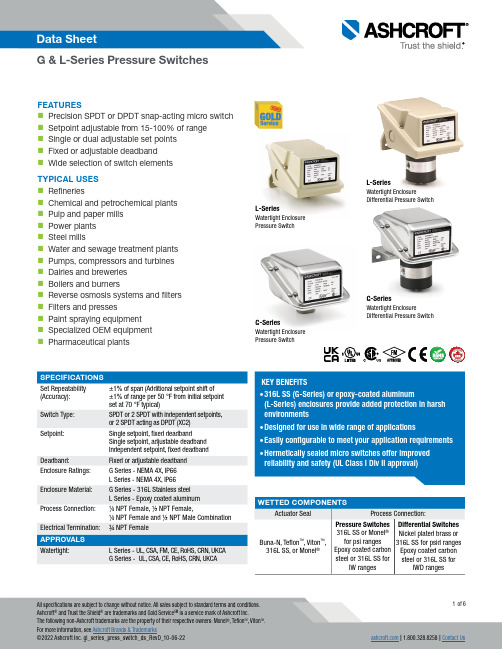
FEATURESPrecision SPDT or DPDT snap-acting micro switch Setpoint adjustable from 15-100% of range Single or dual adjustable set points Fixed or adjustable deadband Wide selection of switch elements TYPICAL USES RefineriesChemical and petrochemical plants Pulp and paper mills Power plants Steel millsWater and sewage treatment plants Pumps, compressors and turbines Dairies and breweries Boilers and burnersReverse osmosis systems and filters Filters and pressesPaint spraying equipment Specialized OEM equipment Pharmaceutical plantsSet Repeatability (Accuracy):±1% of span (Additional setpoint shift of±1% of range per 50 °F from initial setpoint set at 70 °F typical)Switch Type:SPDT or 2 SPDT with independent setpoints,or 2 SPDT acting as DPDT (XC2)Setpoint:Single setpoint, fixed deadbandSingle setpoint, adjustable deadband Independent setpoint, fixed deadbandDeadband:Fixed or adjustable deadband Enclosure Ratings:G Series - NEMA 4X, IP66 L Series - NEMA 4X, IP66Enclosure Material:G Series - 316L Stainless steelL Series - Epoxy coated aluminumProcess Connection:1/4 NPT Female, 1/2 NPT Female,1/4 NPT Female and 1/2 NPT Male CombinationElectrical Termination: ¾ NPT Female Watertight:L Series - UL, CSA, FM, CE, RoHS, CRN, UKCA G Series - UL, CSA, CE, RoHS, CRN, UKCAKEY BENEFITS• environments• • • L-SeriesWatertight EnclosureDifferential Pressure SwitchL-SeriesWatertight Enclosure Pressure SwitchG-SeriesWatertight EnclosureDifferential Pressure SwitchG-SeriesWatertight Enclosure Pressure Switch100# - 100 psi100#®PRESSURE SWITCH – PSI RANGES PRESSURE SWITCH –INCHES OF WATER RANGESDIFFERENTIAL PRESSURE SWITCH –INCHES OF WATER RANGES DIFFERENTIAL PRESSURE SWITCH –PSI DIFFERENTIAL RANGES6.094.12//70A2033 - L-Series D.P. ˝ H2O For reference only, consult Ashcroft for specific dimensional drawingsPRESSURE SWITCH – PSI RANGES PRESSURE SWITCH –INCHES OF WATER RANGESDIFFERENTIAL PRESSURE SWITCH –INCHES OF WATER RANGESDIFFERENTIAL PRESSURE SWITCH –PSI DIFFERENTIAL RANGES70A2113 G Series D.P., psid70A2114 G-SERIES ˝ H2OHIGH PRESSURE PORTLOW PRESSURE PORTFor reference only, consult Ashcroft for specific dimensional drawings。
智能设计MSS如何创建AMBA APB3设计(MSS主机模式)指南说明书

SmartDesign MSS How to Create a MSS and Fabric AMBA APB3 Design(MSS Master Mode)Table of Contents1Configuration and Connectivity . . . . . . . . . . . . . . . . . . . . . . . . . . . . . . . . . . . . . . . . . . . . . . . . . . . . . . . 3 MSS Configuration . . . . . . . . . . . . . . . . . . . . . . . . . . . . . . . . . . . . . . . . . . . . . . . . . . . . . . . . . . . . . . . . . . . . . . . . . . 3 Create the FPGA Fabric and AMBA Subsystem . . . . . . . . . . . . . . . . . . . . . . . . . . . . . . . . . . . . . . . . . . . . . . . . . . . 42Memory Map Computation. . . . . . . . . . . . . . . . . . . . . . . . . . . . . . . . . . . . . . . . . . . . . . . . . . . . . . . . . . . 7 General Formula . . . . . . . . . . . . . . . . . . . . . . . . . . . . . . . . . . . . . . . . . . . . . . . . . . . . . . . . . . . . . . . . . . . . . . . . . . . 7 Memory Map View . . . . . . . . . . . . . . . . . . . . . . . . . . . . . . . . . . . . . . . . . . . . . . . . . . . . . . . . . . . . . . . . . . . . . . . . . . 7A Product Support. . . . . . . . . . . . . . . . . . . . . . . . . . . . . . . . . . . . . . . . . . . . . . . . . . . . . . . . . . . . . . . . . . . 9Customer Service . . . . . . . . . . . . . . . . . . . . . . . . . . . . . . . . . . . . . . . . . . . . . . . . . . . . . . . . . . . . . . . . . . . . . . . . . . 9 Customer Technical Support Center . . . . . . . . . . . . . . . . . . . . . . . . . . . . . . . . . . . . . . . . . . . . . . . . . . . . . . . . . . . . 9 Technical Support . . . . . . . . . . . . . . . . . . . . . . . . . . . . . . . . . . . . . . . . . . . . . . . . . . . . . . . . . . . . . . . . . . . . . . . . . . 9 Website . . . . . . . . . . . . . . . . . . . . . . . . . . . . . . . . . . . . . . . . . . . . . . . . . . . . . . . . . . . . . . . . . . . . . . . . . . . . . . . . . . 9 Contacting the Customer Technical Support Center . . . . . . . . . . . . . . . . . . . . . . . . . . . . . . . . . . . . . . . . . . . . . . . . 9 ITAR Technical Support . . . . . . . . . . . . . . . . . . . . . . . . . . . . . . . . . . . . . . . . . . . . . . . . . . . . . . . . . . . . . . . . . . . . . 101 – Configuration and ConnectivityThe SmartFusion Microcontroller Subsystem enables you to naturally extend the AMBA Bus into theFPGA fabric. You can configure the AMBA fabric interface as either APB3 or AHBLite depending on yourdesign needs. A master and a slave bus interface is available in each mode.This document provides the essential steps to creating an MSS-FPGA fabric AMBA APB3 system usingthe MSS configurator available in the Libero® IDE software.APB peripherals are connected to the MSS using CoreAPB3 version 4.0.100 or greater.The following steps connect APB3 peripherals implemented in the FPGA fabric to the MSS.MSS ConfigurationStep 1. Select the MSS FCLK (GLA0) to fabric clock clock ratio.Select the FAB_CLK divisor in the MSS Clock Management Configurator as shown Figure1-1. You mustperform post-layout static timing analysis to ensure that the design meets the timing requirementsdefined in the Clock Management Configurator. You may have to adjust the clock ratio between the MSSand the fabric to get a functional design.Figure1-1 • Select the MSS FCLK (GLA0/FCLK) to Fabric Clock (FAB_CLK) Clock RatioStep 2. Select the MSS AMBA mode.Select the AMBA APB3 Interface Type in the MSS Fabric Interface Configurator as shown in Figure 1-2. Click OK to continue.The AMBA and FAB_CLK are promoted to Top automatically and are available to any SmartDesign that instantiates the MSS.Create the FPGA Fabric and AMBA SubsystemThe fabric AMBA subsystem is created into a regular SmartDesign component, and then the MSS component is instantiated into that component (as shown in Figure 1-5).Step 1. Instantiate and configure CoreAPB3.APB Master Data Bus Width - 32-bit; the same width of the MSS AMBA data bus.Address Configuration - Varies depending on your slot size; see Table 1-1 for the correct values.Allocate Memory Space to Combined Region Slave - Choose slave slots as necessary.Figure 1-2 •AMBA APB3 Interface SelectedTable 1-1 • Address Configuration Values 64KB Slot Size, upto 11 Slaves4KB Slot Size, up to 16 Slaves 256 Byte Slot Size, up to 16 Slaves 16 Byte Slot Size, up to 16 Slaves Number of address bitsdriven by the master 2016128Position in slave address of upper 4 bits of master address [19:16] (Ignored if master address width >= 24 bits)[15:12] (Ignored ifmaster addresswidth >= 20 bits)[11:8] (Ignored if master address width >= 16 bits)[7:4] (Ignored if master address width >= 12 bits)Indirect Addressing Not in UseEnabled APB Slave Slots - Disable slots that you do not plan to use for your application.The number of slots available for the design is a function of the slot size selected. For 64KB only slots 5 to 15 are available due to fabric visibility from MSS memory map (from 0x4005000 to 0x400FFFFF). For smaller slot sizes, all slots are available. See the "Memory Map Computation" on page 7 for more details about slot sizes and slave/slot connection.Testbench - UserLicense - RTLStep 2. Instantiate and configure AMBA APB peripherals in your design.Step 3. Connect the subsystem together. This can be done automatically or manually. Automatic Connection - The SmartDesign auto-connect feature (available from the SmartDesign Menu, or by right-clicking the Canvas) automatically connects the subsystem clocks and resets and presents you with a Memory Map editor where you can assign the APB slaves to the proper addresses (Figure 1-4).Figure 1-3 •Configure CoreAPB3 to Correspond to your Slot SizeNote that the auto-connect feature performs the clock and reset connections only if the FAB_CLK and M2F_RESET_N port names have not been changed on the MSS component.Manual Connection - Connect the subsystem as follows:•Connect the CoreAPB3 mirrored-master BIF to the MSS Master BIF (as shown in Figure 1-5). •Connect the APB slaves to the proper slots as per your memory map specification.•Connect FAB_CLK to PCLK of all APB peripherals in your design.•Connect M2F_RESET_N to PRESET of all APB peripherals in your design.Figure 1-4 •APB3 Memory MapFigure 1-5 • Manual Connections in SmartDesign Slave Connections2 – Memory Map ComputationOnly the following slot sizes are supported for MSS:•64 KB•4KB and belowGeneral FormulaFor slot size equal to 64K, base address of client peripheral is:0x40000000 + (slot number * slot size)For slot size less than 64K, base address of client peripheral is:0x40050000 + (slot number * slot size)The base address for the fabric is fixed at 0x4005000, but to simplify the memory map equation we showthe base address as different in 64KB case.Note the slot size defines the number of addresses for that peripheral (i.e. 1k means there are 1024addresses).Example 1: 64KB byte slot size64KB slots = 65536 slots (0x10000).If the peripheral is at slot number 7, then, its address is:0x40000000 + ( 0x7 * 0x10000 ) = 0x40070000Example 2: 4KB byte slot size4KB slots = 4096 slots (0x1000)If the peripheral is at slot number 5, then, its address is:0x40050000 + ( 0x5 * 0x800 ) = 0x40055000Memory Map ViewYou can view the system memory map by using the Reports feature (from the Design menu chooseReports). For example, Figure2-1 is a partial memory map generated for the subsystem shown inFigure1-5 on page6.Figure2-1 • Memory MapA – Product SupportMicrosemi SoC Products Group backs its products with various support services, including CustomerService, Customer Technical Support Center, a website, electronic mail, and worldwide sales offices.This appendix contains information about contacting Microsemi SoC Products Group and using thesesupport services.Customer ServiceContact Customer Service for non-technical product support, such as product pricing, product upgrades,update information, order status, and authorization.From North America, call 800.262.1060From the rest of the world, call 650.318.4460Fax, from anywhere in the world, 408.643.6913Customer Technical Support CenterMicrosemi SoC Products Group staffs its Customer Technical Support Center with highly skilledengineers who can help answer your hardware, software, and design questions about Microsemi SoCProducts. The Customer Technical Support Center spends a great deal of time creating applicationnotes, answers to common design cycle questions, documentation of known issues, and various FAQs.So, before you contact us, please visit our online resources. It is very likely we have already answeredyour questions.Technical SupportVisit the Customer Support website (/soc/support/search/default.aspx) for moreinformation and support. Many answers available on the searchable web resource include diagrams,illustrations, and links to other resources on the website.WebsiteYou can browse a variety of technical and non-technical information on the SoC home page, at/soc.Contacting the Customer Technical Support CenterHighly skilled engineers staff the Technical Support Center. The Technical Support Center can becontacted by email or through the Microsemi SoC Products Group website.EmailYou can communicate your technical questions to our email address and receive answers back by email,fax, or phone. Also, if you have design problems, you can email your design files to receive assistance.We constantly monitor the email account throughout the day. When sending your request to us, pleasebe sure to include your full name, company name, and your contact information for efficient processing ofyour request.The technical support email address is **********************.© 2013 Microsemi Corporation. All rights reserved. Microsemi and the Microsemi logo are trademarks of Microsemi Corporation. All other trademarks and service marks are the property of their respective owners.Microsemi Corporation (NASDAQ: MSCC) offers a comprehensive portfolio of semiconductor solutions for: aerospace, defense and security; enterprise and communications; and industrial and alternative energy markets. Products include high-performance, high-reliability analog and RF devices, mixed signal and RF integrated circuits, customizable SoCs, FPGAs, and complete subsystems. Microsemi is headquartered in Aliso Viejo, Calif. Learn more at .Microsemi Corporate HeadquartersOne Enterprise, Aliso Viejo CA 92656 USAWithin the USA: +1 (949) 380-6100Sales: +1 (949) 380-6136Fax: +1 (949) 215-4996My CasesMicrosemi SoC Products Group customers may submit and track technical cases online by going to My Cases .Outside the U.S.Customers needing assistance outside the US time zones can either contact technical support via email (**********************) or contact a local sales office. Sales office listings can be found at /soc/company/contact/default.aspx.ITAR Technical SupportFor technical support on RH and RT FPGAs that are regulated by International Traffic in Arms Regulations (ITAR), contact us via ***************************. Alternatively, within My Cases , select Yes in the ITAR drop-down list. For a complete list of ITAR-regulated Microsemi FPGAs, visit the I TAR web page.。
小凡模拟器教程

现在新手学cisco的,基本都在用Dynamips和PT ,但是很多新手不会使用Dynamips,或许你看了这篇文章之后,至少会对Dynamips有点认识,应该基本都会用了。
Now,Follow Me 。
看图说话:按照图中用数字标出的序号来解释该区域:区域1:这里是选择路由器和交换机的个数的,这个地球人应该都知道吧。
区域2:这里可以选择一些不需要Cisco IOS的模拟设备。
如:FrameRelay交换机ATM交换机。
区域3:这里是选择设备类型的,以上都是Dynamips目前所支持的设备类型。
区域4:这里是选择设备类型、IOS存放路径、idle-pc值、NPE类型、虚拟内存(表示虚拟设备的RAM所占的内存大小,因为dynamips在模拟时候需要将主机的物理内存模拟成模拟设备的RAM)、寄存器。
区域5:这里是配置分布式的dynamips的设置区域区域6:这里是设置可以和主机(就是你的物理机)通信的。
区域7:可以直接读取真实设备里的NVRAM里的配置文件(.ini格式)区域8:输入目录是指生成的bat文件保存路径,自己建立哦。
下面根据拓扑来介绍:根据这个拓扑,需要模拟出3个路由器和1个交换机。
下面我们用DynamipsGUI 来配置脚本文件。
(Ps:DynamipsGUI和Dynamipsee都是可视化的写Dynamips的脚本程序。
不是模拟器!!真正的模拟器是Dynamips 。
)下面模拟上面的拓扑全过程:1.打开DynamipsGUI。
然后在[区域1]那里选择3个路由器和1个交换机。
并且选择[桥接到PC](桥接到PC的作用就是用物理机telnet到模拟出来的设备,然后就可以对设备进行配置),在这里路由器我用的IOS是7200的,交换机用的是3640的(IOS网上很多,可以自己去找。
),所以总的来说我只需要2个IOS文件既可,所以在设备类型这里我只需要勾选7200和3640这2个复选框既可。
如图:2.接着就是在[区域2]那里选择设备的类型和IOS文件路径,选择好之后,需要计算idle值,点击[计算idle]按钮(idle-pc只是为了解决在开启模拟设备的时候不至于你的物理机CPU占有率达到100%,所以这个值很重要)3.点击[计算idle]按钮之后,会弹出一个提示,选择确定即可:4.接着就会弹出一个窗口。
CoreSPI_HB
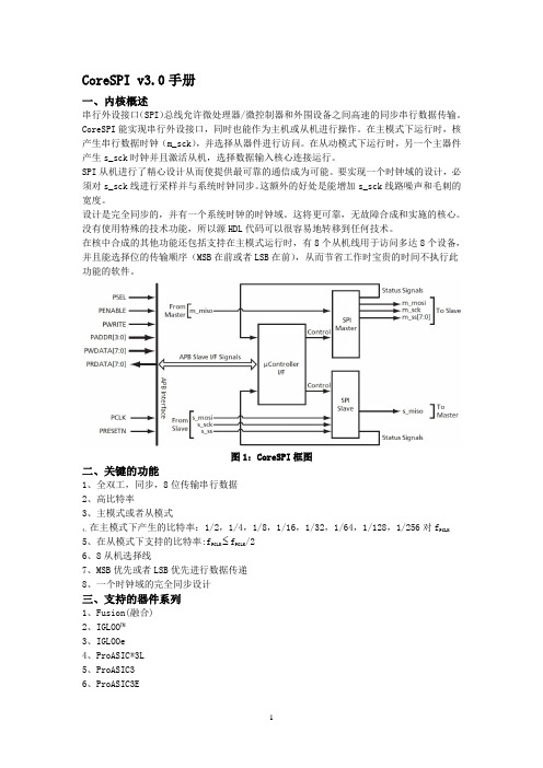
CoreSPI v3.0手册一、内核概述串行外设接口(SPI)总线允许微处理器/微控制器和外围设备之间高速的同步串行数据传输。
CoreSPI能实现串行外设接口,同时也能作为主机或从机进行操作。
在主模式下运行时,核产生串行数据时钟(m_sck),并选择从器件进行访问。
在从动模式下运行时,另一个主器件产生s_sck时钟并且激活从机,选择数据输入核心连接运行。
SPI从机进行了精心设计从而使提供最可靠的通信成为可能。
要实现一个时钟域的设计,必须对s_sck线进行采样并与系统时钟同步。
这额外的好处是能增加s_sck线路噪声和毛刺的宽度。
设计是完全同步的,并有一个系统时钟的时钟域。
这将更可靠,无故障合成和实施的核心。
没有使用特殊的技术功能,所以源HDL代码可以很容易地转移到任何技术。
在核中合成的其他功能还包括支持在主模式运行时,有8个从机线用于访问多达8个设备,并且能选择位的传输顺序(MSB在前或者LSB在前),从而节省工作时宝贵的时间不执行此功能的软件。
图1:CoreSPI框图二、关键的功能1、全双工,同步,8位传输串行数据2、高比特率3、主模式或者从模式4、在主模式下产生的比特率:1/2,1/4,1/8,1/16,1/32,1/64,1/128,1/256对f PCLK5、在从模式下支持的比特率:f PCLK f PCLK/26、8从机选择线7、MSB优先或者LSB优先进行数据传递8、一个时钟域的完全同步设计三、支持的器件系列1、Fusion(融合)2、IGLOO™3、IGLOOe4、ProASIC®3L5、ProASIC36、ProASIC3E四、设备利用率和性能CoreSPI可以在任何Actel的设备上实现。
CoreSPI各种设备的利用率和性能的总结在表1到表3中列出。
用于布局的速度等级如下:IGLOO系列:STD,融合:-2,ProASIC3 / E:-2,ProASIC PLUS®:STD,Axcelerator®:-2,RTAX - S:-1。
Actel-APB3总线使用

APB3总线实用心得本心得是基于SmartFusion的学习心得, 主要是关于APB3总线的使用。
在此以示例说明1.创建新项目, 在此不做详细说明;2、配置Cortex-M3内核功能, 可以根据工程项目需求配置相应的模块, 需要保留的模块勾选上, 不需要的去掉勾选项, 如图1所示;图1 模块选择示图3.由于使用了APB3总线, 在此必须配置“Fabric Interface”模块, 如图2所示;图2 总线功能模块4.在此实例中Cortex-M3内核模块作为Master模式使用, 在配置的时候, 几口类型“Interface Type”有两种, AHB总线是多“Master”多“Slave”的总线形式, APB3是单一“Master”多“Slave”的总线形式。
两种中线器基本原理相同, 但是APB3总线使用相对简单一些, 在此选择APB3总线。
另外总线接口有“Master”和“Slave”两种, 其中“Master”的功能是具有主动控制的功能, 凸显主动模性;“Slave”的功能是被动功能, 凸显被动性。
在此选择“Master”接口, 即在整个工程中的作用是使Cortex-M3内核能够读写控制FPGA。
配置图如图3所示。
图3 总线配置图图4 功能5.根据功能配置好Cortex-M3内核之后, 更新该模块, 更新后的模块如图4所示。
6.用VHDL(Verilog)语言添加具有Slave接口的模块, 在此添加一个计数器模块, 接口如图5所示。
除去最后一个接口信号, 其他为APB3标准接口信号, 必须添加, 其他的信号可以根据功能需求添加。
为做简化, 添加另外两个计数器模块, 除实体定义名称不同, 其功能完全一样, 在此不做说明。
图5 实体信号示例图7、创建模块总线。
首先, 选择项目选项卡, 如图6所示。
图6 项目选项卡其次, 创建模块核, 如图7, 图8所示, 右键首次创建核的文件, 选择“Create Core from HDL..”, 如果出现确认对话框, 选择“Yes”即可。
apb协议 pmaster信号

APB协议Pmaster信号1. 介绍APB(Advanced Peripheral Bus)协议是一种由ARM公司开发的,用于连接处理器和外设的串行总线协议。
Pmaster信号是APB协议中的一种重要信号,用于控制总线的访问和数据传输。
2. APB协议概述APB协议是一种简单、低功耗、低成本的总线协议,适用于连接处理器和外设的通信。
它允许外设以低速访问处理器的寄存器和内存,提供了一种灵活的通信方式。
3. Pmaster信号作用Pmaster信号是APB协议中的一个重要信号,用于控制总线的访问和数据传输。
它由处理器发出,用于向外设发送请求和控制信号。
3.1 Pmaster信号的类型Pmaster信号包括以下几种类型: - PADDR:指定要访问的地址; - PSEL:指定要访问的外设; - PENABLE:使能信号,表示进行访问操作; - PWRITE:写使能信号,表示进行写操作; - PWDATA:写数据信号,用于传输写入的数据; - PRDATA:读数据信号,用于传输读取的数据; - PREADY:准备好信号,表示外设已经准备好进行数据传输; - PSLVERR:总线错误信号,表示发生了总线错误。
3.2 Pmaster信号的时序Pmaster信号的时序如下: 1. 处理器发出PADDR信号,指定要访问的地址; 2. 处理器发出PSEL信号,指定要访问的外设; 3. 处理器发出PENABLE信号,使能访问操作; 4. 若进行写操作,处理器同时发出PWRITE信号和PWDATA信号,传输写入的数据; 5. 外设通过PREADY信号表示已经准备好进行数据传输; 6. 外设通过PRDATA信号传输读取的数据; 7. 若发生总线错误,外设通过PSLVERR信号进行错误报告。
4. APB协议操作流程APB协议的操作流程如下所示:1.处理器发出PADDR信号,指定要访问的地址;2.处理器发出PSEL信号,指定要访问的外设;3.处理器发出PENABLE信号,使能访问操作;4.若进行写操作,处理器同时发出PWRITE信号和PWDATA信号,传输写入的数据;5.外设接收到PENABLE信号后,开始处理请求;6.若发生总线错误,外设发出PSLVERR信号进行错误报告;7.外设通过PREADY信号表示已经准备好进行数据传输;8.外设通过PRDATA信号传输读取的数据;9.外设完成数据传输后,处理器接收到PREADY信号,表示数据传输完成。
apb协议 pmaster信号

apb协议pmaster信号摘要:1.APB 协议简介2.PMaster 信号的作用3.PMaster 信号的工作原理4.PMaster 信号的应用场景5.总结正文:1.APB 协议简介APB(Advanced Peripheral Bus)协议是一种先进的外围总线协议,常用于连接微控制器(MCU)和其外围设备,如存储器、传感器和驱动器等。
APB 协议的主要特点是传输速度快、总线负载能力强以及支持多主控制器结构。
在APB 协议中,数据传输可以通过两种方式进行:同步传输和异步传输。
2.PMaster 信号的作用PMaster 信号是APB 协议中的一个重要信号,主要用于控制数据传输的时序。
在APB 总线上,有一个或多个主设备(Master)负责发起和控制数据传输过程。
PMaster 信号可以使得主设备在不同的时钟周期中控制数据传输的不同阶段,如数据发送、数据接收和传输结束等。
3.PMaster 信号的工作原理PMaster 信号的工作原理与APB 协议的数据传输过程密切相关。
在APB 总线上,数据传输过程可以分为多个时钟周期。
在每个时钟周期中,PMaster 信号会根据APB 协议的时序要求,控制主设备的数据传输行为。
具体来说,PMaster 信号会通过控制传输使能(TXE)、传输请求(TREQ)和数据有效(DV)等信号,使得主设备在正确的时序节点上进行数据发送、接收和确认。
4.PMaster 信号的应用场景PMaster 信号在APB 协议中具有广泛的应用。
在实际的嵌入式系统中,PMaster 信号通常用于以下场景:(1)控制数据传输:PMaster 信号可以控制主设备在APB 总线上进行数据传输,使得数据能够在各个设备之间高效地传输和共享。
(2)时序控制:PMaster 信号可以根据APB 协议的时序要求,对数据传输过程进行精确的时序控制,保证数据传输的稳定性和可靠性。
(3)多主设备协同:在多主设备结构中,PMaster 信号可以使得不同的主设备在APB 总线上协同工作,实现高效的数据传输和共享。
Eaton Moeller B3三相总线连接器说明书

Eaton 063961Eaton Moeller® series B3 Three-phase busbar link, Circuit-breaker:2, 90 mm, For PKZM0-... or PKE12, PKE32 without side mountedauxiliary contacts or voltage releasesGeneral specificationsEaton Moeller® series B3 AccessoryThree-phase busbar link063961401508063961990 mm34 mm11 mm0.035 kgCSA-C22.2 No. 14UL File No.: E36332CSA File No.: 98494UL Category Control No.: NLRV CEIEC/EN 60947-4-1CSAUL 508CSA Class No.: 3211-06UL For parallel power feed to several motor-protective circuit-breakers on terminals 1, 3, 5Product Name Catalog NumberEANProduct Length/Depth Product Height Product Width Product Weight Certifications Catalog Notes63 AIs the panel builder's responsibility. The specifications for the switchgear must be observed.Meets the product standard's requirements.Is the panel builder's responsibility. The specifications for the switchgear must be observed.Does not apply, since the entire switchgear needs to be evaluated.Meets the product standard's requirements.Is the panel builder's responsibility.6 KV0 kA45 mm55 °C0 mm²Black5Insulated0 W DA-DC-00004887.pdfDA-DC-00004951.pdfDA-DC-00004892.pdfDA-DC-00004883.pdfDA-DC-00004884.pdfDA-DC-00004944.pdfDA-DC-00004962.pdfDA-DC-00004914.pdfDA-DC-00004921.pdfDA-DC-00004917.pdfDA-DC-00004945.pdfDA-DC-00004891.pdfDA-DC-00004888.pdfDA-DC-00004890.pdfDA-DC-00004879.pdfDA-DC-00004911.pdfDA-DC-00004920.pdfDA-DC-00004918.pdfeaton-manual-motor-starters-busbar-b3-accessory-dimensions-006.eps eaton-manual-motor-starters-busbar-b3-accessory-3d-drawing-002.epsDA-CE-ETN.B3.0_2-PKZ0DA-CD-b3_0_2_pkz0DA-CS-b3_0_2_pkz0DA-DC-00004109.pdfDA-DC-00004245.pdfDA-DC-00004544.pdfDA-DC-00004601.pdfRated operational current for specified heat dissipation (In) 10.11 Short-circuit rating10.4 Clearances and creepage distances10.12 Electromagnetic compatibility10.2.5 Lifting10.2.3.1 Verification of thermal stability of enclosures10.8 Connections for external conductorsRated surge voltageRated conditional short-circuit current (Iq)Pitch dimensionsAmbient operating temperature - maxCross sectionColorNumber of modular spacingsFeaturesStatic heat dissipation, non-current-dependent Pvs10.9.3 Impulse withstand voltage Declarations of conformityDibujoseCAD modelmCAD modelReportes de certificacionesIs the panel builder's responsibility.Number of polesThree-poleAmbient operating temperature - min-25 °C10.6 Incorporation of switching devices and componentsDoes not apply, since the entire switchgear needs to be evaluated.10.5 Protection against electric shockDoes not apply, since the entire switchgear needs to be evaluated.Used withPKZ0PKE12PKE32Rated uninterrupted current (Iu)63 AElectric connection typeFork10.13 Mechanical functionThe device meets the requirements, provided the information in the instruction leaflet (IL) is observed.10.2.6 Mechanical impactDoes not apply, since the entire switchgear needs to be evaluated.10.9.4 Testing of enclosures made of insulating materialIs the panel builder's responsibility.10.3 Degree of protection of assembliesDoes not apply, since the entire switchgear needs to be evaluated.Heat dissipation per pole, current-dependent Pvid1 WProduct categoryAccessoriesEquipment heat dissipation, current-dependent Pvid3 WHeat dissipation capacity Pdiss0 WSuitable for2 Circuit-breakersSuitable for number of devices210.2.3.2 Verification of resistance of insulating materials to normal heatMeets the product standard's requirements.10.2.3.3 Resist. of insul. mat. to abnormal heat/fire by internal elect. effectsMeets the product standard's requirements.Number of phases310.9.2 Power-frequency electric strengthIs the panel builder's responsibility.Overvoltage categoryIIIRated short-time withstand current (Icw)0 kARated operational voltage (Ue) at AC - max690 VPollution degree310.7 Internal electrical circuits and connectionsIs the panel builder's responsibility.Rated impulse withstand voltage (Uimp)6000 V AC10.10 Temperature riseThe panel builder is responsible for the temperature rise calculation. Eaton will provide heat dissipation data for the devices.FunctionsCan be extended by rotating installation10.2.2 Corrosion resistanceMeets the product standard's requirements.10.2.4 Resistance to ultra-violet (UV) radiationMeets the product standard's requirements.10.2.7 InscriptionsMeets the product standard's requirements.Eaton Corporation plc Eaton House30 Pembroke Road Dublin 4, Ireland © 2023 Eaton. Todos los derechos reservados. Eaton is a registered trademark.All other trademarks areproperty of their respectiveowners./socialmedia690 V 45 mmRated operational voltage (Ue) - max Mounting width。
ELAC PB30-S 3-Outlet Slim Surge Protector 使用指南说明书
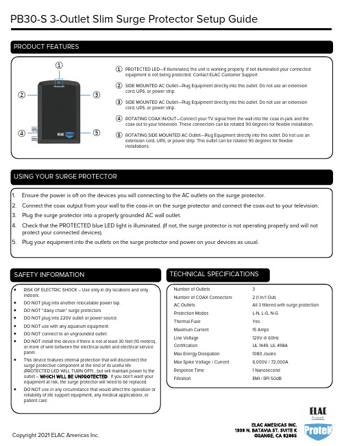
PB30-S 3-Outlet Slim Surge Protector Setup Guide① PROTECTED LED—If illuminated, the unit is working properly. If not illuminated your connectedequipment is not being protected. Contact ELAC Customer Support.② SIDE MOUNTED AC Outlet—Plug Equipment directly into this outlet. Do not use an extensioncord, UPS, or power strip.③ SIDE MOUNTED AC Outlet—Plug Equipment directly into this outlet. Do not use an extensioncord, UPS, or power strip.④ ROTATING COAX IN/OUT—Connect your TV signal from the wall into the coax in-jack and thecoax out to your television. These connectors can be rotated 90 degrees for flexible installation.⑤ ROTATING SIDE MOUNTED AC Outlet—Plug Equipment directly into this outlet. Do not use anextension cord, UPS, or power strip. This outlet can be rotated 90 degrees for flexible installations.①③② 1. Ensure the power is off on the devices you will connecting to the AC outlets on the surge protector.2. Connect the coax output from your wall to the coax-in on the surge protector and connect the coax-out to your television.3. Plug the surge protector into a properly grounded AC wall outlet.4. Check that the PROTECTED blue LED light is illuminated. (If not, the surge protector is not operating properly and will notprotect your connected devices). 5. Plug your equipment into the outlets on the surge protector and power on your devices as usual.• RISK OF ELECTRIC SHOCK – Use only in dry locations and only indoors.• DO NOT plug into another relocatable power tap. • DO NOT “daisy chain” surge protectors. • DO NOT plug into 220V outlet or power source. • DO NOT use with any aquarium equipment. • DO NOT connect to an ungrounded outlet.• DO NOT install this device if there is not at least 30 feet (10 meters), or more of wire between the electrical outlet and electrical service panel.•This device features internal protection that will disconnect the surge protective component at the end of its useful life(PROTECTED LED WILL TURN OFF) , but will maintain power to the outlet – WHICH WILL BE UNPROTECTED . If you don’t want your equipment at risk, the surge protector will need to be replaced. •DO NOT use in any circumstance that would affect the operation or reliability of life support equipment, any medical applications, or patient care.Number of Outlets3Number of COAX Connectors 2 (1 In/1 Out)AC Outlets All 3 filtered with surge protection Protection Modes L-N, L-G, N-G Thermal Fuse Yes Maximum Current 15 Amps Line Voltage 120V @ 60Hz CertificationUL 1449, UL 498A Max Energy Dissipation 1080 Joules Max Spike Voltage / Current 6,000V / 72,000A Response Time 1 Nanosecond FiltrationEMI / RFI 50dB⑤④ELAC Americas Inc. warrants to the original purchaser that this product be free from defects and or workmanship for lifetime of this product from the original date of purchase. During this time period, repair or replacement will be free of charge to the original owner (See below limitations). Shipping to and return from the repair center will be the responsibility of the original purchaser. Limitations• Warranty begins on the date of original purchase from an authorized ELAC Americas Inc. dealer. Products purchased from an unauthorized reseller will not be honored.• Product is warranted only if used in home applications within the rated specifications of this product. Commercial use of this product is not warranted.• Product that has been modified or altered in anyway will not be warranted.• Product that has been abused or subjected to faulty equipment will not be warranted.• Products with defaced or removed serial numbers will not be warranted.If service is requiredIntheeventthatserviceisrequired,*************************************************************************** return authorization and to arrange for service or replacement. Whether the product will be serviced or replaced is at ELAC’s discretion. You will be responsible to provide proof of purchase (Copy or original sales receipt). Shipping to and from our repair center will be the responsibility of the original purchaser.This surge protector is designed to protect your electronic equipment from AC power surges up to its rated specifications only. If an electrical surge above the rated specifications of this surge protector enter this device, connected devices may not be protected. Please understand that electrical surges can enter electronics devices through any interconnected conductive connections. These interconnections can include coax lines, phone lines, ethernet lines, AV connections and any other conductive material.。
Actel推出FPGA上电解决方案
Actel推出FPGA上电解决方案
无
【期刊名称】《电子测试:新电子》
【年(卷),期】2005(000)011
【摘要】Actel公司日前公布最新的实验结果,表明其非挥发性FPGA的上电响应速度比以SRAM为基础的同类型产品快4,000倍,成功为可编程逻辑业界带来高速上电性能。
上电即行(Live At Power—Up.LAPU)单芯片FPGA无需额外的上电和初始化电路,因此能降低整体系统成本。
非挥发性FPGA技术的LAPU 特性使其成为汽车、消费电子、医疗、军品以及那些需要即时进入操作状态应用的理想方案,同时能降低整体系统成本。
【总页数】1页(P106)
【作者】无
【作者单位】无
【正文语种】中文
【中图分类】TN791
【相关文献】
1.Actel推出基于IGLOO FPGA的便携控制解决方案 [J],
2.FPGA嵌入式微处理器软核迎向开放时代Actel推出专为FPGA而优化的32位ARM软核系列 [J], 任苙萍
3.Actel推出第三代以Flash为基础器件为业界奠下最低价FPGA解决方案的标准[J],
4.ACTEL欢迎新设计服务公司加盟解决方案合作伙伴计划——合作伙伴的设计服务、硬件和工具软件与Actel的FPGA产品相辅相成 [J],
5.Actel推快速FPGA上电进一步调低整体成本 [J],
因版权原因,仅展示原文概要,查看原文内容请购买。
- 1、下载文档前请自行甄别文档内容的完整性,平台不提供额外的编辑、内容补充、找答案等附加服务。
- 2、"仅部分预览"的文档,不可在线预览部分如存在完整性等问题,可反馈申请退款(可完整预览的文档不适用该条件!)。
- 3、如文档侵犯您的权益,请联系客服反馈,我们会尽快为您处理(人工客服工作时间:9:00-18:30)。
APB3总线实用心得
本心得是基于SmartFusion的学习心得,主要是关于APB3总线的使用。
在此以示例说明
1、创建新项目,在此不做详细说明;
2、配置Cortex-M3内核功能,可以根据工程项目需求配置相应的模块,需要保留的模块勾选上,不需要的去掉勾选项,如图1所示;
图1 模块选择示图
3、由于使用了APB3总线,在此必须配置“Fabric Interface”模块,如图2所示;
图2 总线功能模块
4、在此实例中Cortex-M3内核模块作为Master模式使用,在配置的时候,几口类型“Interface Type”有两种,AHB总线是多“Master”多“Slave”的总线形式,APB3是单一“Master”多“Slave”的总线形式。
两种中线器基本原理相同,但是APB3总线使用相对简单一些,在此选择APB3总线。
另外总线接口有“Master”和“Slave”两种,其中“Master”的功能是具有主动控制的功能,凸显主动模性;“Slave”的功能是被动功能,凸显被动性。
在此选择“Master”接口,即在整个工程中的作用是使Cortex-M3内核能够读写控制FPGA。
配置图如图3所示。
图3 总线配置图
图4 功能
5、根据功能配置好Cortex-M3内核之后,更新该模块,更新后的模块如图4所示。
6、用VHDL(Verilog)语言添加具有Slave接口的模块,在此添加一个计数器模块,接口如图5所示。
除去最后一个接口信号,其他为APB3标准接口信号,必须添加,其他的信号可以根据功能需求添加。
为做简化,添加另外两个计数器模块,除实体定义名称不同,其功能完全一样,在此不做说明。
图5 实体信号示例图
7、创建模块总线。
首先,选择项目选项卡,如图6所示。
图6 项目选项卡
其次,创建模块核,如图7,图8所示,右键首次创建核的文件,选择“Create Core from HDL..”,如果出现确认对话框,选择“Yes”即可。
图7 创建核与编辑核菜单选项
图8 核编辑界面
8、添加总线,点击图8中的“Add/Edit bus interfaces..”按键,出现如图9所示界面,点击图9中的“Add bus interfaces..”按键,出现如图10所示界面,选择蓝色标注的总线,即APB3总线Slave接口。
图9 总线添加界面
图10 总线接口选择界面
9、建立总线联系,由于FPGA实体接口定义的信号名称和总线接口的名称相同,所以会根据名称自动匹配相关信号,如图11所示,只有一个信号“PSELx”未匹配,在此需要手动选择,如图12所示。
之后点击两次“OK”结束总线配置。
图11 信号匹配图
图12
10、添加具有Slave总线的计数器模块,从左侧选择需要模块,左键拖放至右侧设计窗口,计数器模块如图13所示。
该模块具有BIF_1总线,输入时钟PCLK,复位信号PRESTn,计数器进位信号,同时也作为Cortex-M3的一个GPIO中断输入信号。
按照步骤7-9,添加其他两个计数器模块
图13 计数器模块
11、添加APB3总线模块,选择项目选项卡“Catlog”,如图14所示,从左侧选择“Bus Interfaces”里面的“CoreAPB3”模块,直接左键拖放至右侧设计窗口,如图15所示
图14
图15 APB3总线
12、双击该模块,出现图16所示配置界面。
其中包括数据位宽设置、地址设置区和从节点选择区,按照图16所示设置总线参数。
图16 APB总线配置界面
13、连接总线和模块,如图17所示,按图示蓝色线连接总线和个模块
图17 总线和模块连接图
14、查看地址范围,右键点击总线模块,出现图18所示菜单,并选择“Modify Memory Map”菜单项,查看分配的地址空间,如图19所示。
图中所示地址为每个模块分配的地址空间的基地址,根据之前分配的地址位宽情况可以确定完整的地址空间。
图18
图19 地址空间分配
15、在FPGA程序设计中,计数器模块为从节点,设置地址常数时,地址长度为12位,由于数据位宽为32位,4个字节,所以使用地址,地址数值按4递增。
在ARM程序设计中,地址的分配也是按4递增。
注意:在分配具体的的地址数值时,主节点分配地址必须是地址空间内的完整地址,从节点地址为12位宽度的完整地址。
在ARM程序设计中地址的使用和标准C语言的使用方式一样。
图20 FPGA从节点地址使用
图21 ARM主节点地址使用
对于FPGA设计,当总线操作的时候,首先判断读写控制信号,当PWRITE=1时,此时输入数据,当PWRITE=0时,此时输出数据。
当PWRITE=1时,此时为输入数据。
根据功能判定其他相关的控制信号是否有效,即PSEL = '1' and PENABLE = '1。
当该条件成立时,在判定地址PADDR,根据地址情况获取对应的有效数据。
情况如下:
COUNTERENABLE对应信号CounterEn,获取有效位PWDATA(0)
COUNTERLOADA对应信号Load,获取有效位PWDATA(31 downto 0) 为此,在ARM程序设计中只要改变相应位的数据即可。
当PWRITE=0时,此时为输出数据。
根据功能判定其他相关的控制信号是否有效,即PSEL = '1'。
当该条件成立时,在判定地址PADDR,根据地址情况获
取对应的有效数据,在此不做说明。
以上为APB3总线的基本使用方式。
