REC10-4812SRWZH中文资料
BAC4812 蓄电池充电器 用户手册说明书

BAC4812蓄电池充电器用户手册郑州众智科技股份有限公司ZHENGZHOU SMARTGEN TECHNOLOGY CO.,LTD.目 次前言 (3)1概述 (4)2性能特点 (4)3充电原理 (4)4参数规格 (5)5设置 (6)5.1电压调节 (6)5.2电流调节 (6)6操作说明 (6)7外形及安装尺寸 (7)前 言是本公司的中文商标是本公司的英文商标SmartGen―smart的意思是灵巧的、智能的、聪明的,gen是generator(发电机组)的缩写,两个单词合起来的意思是让发电机组变得更加智能。
不经过本公司的允许,本文档的任何部分不能被复制(包括图片及图标)。
本公司保留更改本文档内容的权利,而不通知用户。
公司地址:中国.河南省郑州市高新技术产业开发区金梭路28号电话:+86-371-67988888+86-371-67981888+86-371-67991553+86-371-67992951+86-371-67981000(外贸)全国免费电话:400-0318-139传真:+86-371-67992952网址://邮箱:*****************表1版本发展历史日期版本内容2016-06-24 1.0开始发布1概述BAC4812系列蓄电池充电器采用最新开关电源器件,专门针对发动机起动用的铅酸蓄电池的充电特性而设计,适合铅酸电池的长期补充充电(浮充)。
此款充电器适用于12V蓄电池组充电,其最大充电电流为3A。
2性能特点产品有以下特点:a)采用开关电源式结构,输入电压范围宽,体积小,重量轻,效率高。
b)采用二阶段充电法(即先恒流后恒压方式)自动充电,充分按照蓄电池充电特性进行充电,可防止铅酸蓄电池过充电,能最大程度提高电池寿命。
c)具有辅助电压输出口,稳定输出-12V电压。
d)+12V输出具有短路及接反保护功能。
e)-12V输出具有短路自恢复功能。
f)充电电压、电流值均可在现场通过电位器调节。
Recom RP100H-RW DC DC 转换器产品说明书
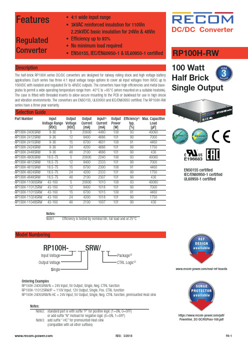
FeaturesRegulated Converter• 4:1 wide input range• 3kVAC reinforced insulation for 110Vin 2.25kVDC basic insulation for 24Vin & 48Vin • Efficiency up to 93%• No minimum load required• EN50155, IEC/EN60950-1 & UL60950-1 certifiedDescriptionThe half-brick RP100H series DC/DC converters are designed for railway rolling stock and high voltage battery applications. Each series has three 4:1 input voltage range options to cover all input voltages from 9VDC up to 160VDC with isolated and regulated 5V to 48VDC outputs. The converters have high efficiencies and metal base-RP100H-RW DC/DC Converter100 Watt Half BrickEN50155 certifiedIEC/EN60950-1 certified UL60950-1 certifiedE196683RP100H-2415SRW 9-36 15 6700 4601 100 91 4460RP100H-2424SRW 9-36 24 4200 4666 101 90 1750RP100H-2448SRW 9-36 48 2100 4666 101 90 430RP100H-4805SRW 16.5-75 5 20000 2240 100 93 40000RP100H-4812SRW 16.5-75 12 8400 2333 101 90 7000RP100H-4815SRW 16.5-75 15 6700 2300 100 91 4460RP100H-4824SRW 16.5-75 24 4200 2333 101 90 1750RP100H-4848SRW 16.5-75 48 2100 2307 101 90 430RP100H-11005SRW 43-160 5 20000 1010 100 93 40000RP100H-11012SRW 43-160 12 8400 1018 101 90 7000RP100H-11015SRW 43-160 15 6700 1015 100 91 4460RP100H-11024SRW 43-160 24 4200 1018 101 90 1750RP100H-11048SRW 43-160 48 2100 1007 101 90 430Ordering ExamplesRP100H-2405SRW/N = 24V Input, 5V Output, Single, Neg. CTRL function RP100H-11012SRW/P = 110V Input, 12V Output, Single, Pos. CTRL functionRP100H-2405SRW/N-HC = 24V Input, 5V Output, Single, Neg. CTRL function, premounted Heat-sinkModel NumberingInput Voltage Output VoltageS ingleRP100H-__ __SRW/_ _Notes:Note2: standard part is with suffix “P” for positive logic (1=ON, 0=OFF) or add suffix “N” instead for negative logic (0=ON, 1=OFF) Note3: add suffix “-HC” for premounted Heat-sink CTRL Logic (2)Package (3)Notes:Note1:Efficiency is tested by nominal Vin, full load and at 25°Chttps:///pdf/Powerline_DC-DC/RSPxxx-168.pdf/eval-ref-boardsSpecifications (measured @Ta = 25°C, resistive load, nominal Vin and rated Iout unless otherwise noted)Specifications (measured @Ta = 25°C, resistive load, nominal Vin and rated Iout unless otherwise noted)RP100H-4805SRW708090100Efficiency vs. Output CurrentPower up Start-up CharacteristicON/OFF Control Start-up Rise CharacteristicSpecifications (measured @Ta = 25°C, resistive load, nominal Vin and rated Iout unless otherwise noted)Efficiency vs. Input Voltage60708090100708010090RP100H-11005SRWEfficiency vs. Output CurrentPower up Start-up CharacteristicSpecifications (measured @Ta = 25°C, resistive load, nominal Vin and rated Iout unless otherwise noted)OUTPUT TRIM Typical Output Ripple and NoisePower up Start-up CharacteristicOutput Voltage TrimmingRP100H-RW converters offer the feature of trimming the output voltage over a certain range around the nominal value by using external trim resistors. The values for trim resistors shown in trim tables below are according to standard E96 values; therefore, the specified voltage may slightly vary; they also can be calculated with below shown equation.TRIM DOWNTRIM UPTRIM-Sense+SenseSpecifications (measured @Ta = 25°C, resistive load, nominal Vin and rated Iout unless otherwise noted)OUTPUT TRIMRP100H-xx05SRWRP100H-xx12SRWRP100H-xx15SRWRP100H-xx24SRWRP100H-xx48SRWTrim Down all Vout‘sTrim up 12345678910%Vout = 5.05 5.10 5.15 5.20 5.25 5.30 5.35 5.4 5.45 5.50Volts R 1 = 30915810578.763.453.646.440.236.533.2kOhms Trim up 12345678910%Vout =12.1212.2412.3612.4812.6012.7212.8412.9613.0813.20Volts R 1 = 88745330122618215413311810595.3kOhms Trim up 12345678910%Vout =15.1515.3015.4515.6015.7515.9016.0516.2016.3516.50Volts R 1 = 1130576383294237196169150137124kOhms Trim up 12345678910%Vout =24.2424.4824.7224.9625.2025.4425.6825.9226.1626.40Volts R U = 1870953634487392324280249226205kOhms Trim up 12345678910%Vout =48.4848.9649.4449.9250.4050.8851.3651.8452.3252.80Volts R 1 = 3830196013001000806681576511464422kOhms Trim down 12345678910%R 2 = 97.647.531.623.217.814.712.110.59.098.06kOhms Trim down 11121314151617181920%R 2 =7.156.345.765.114.644.223.923.573.243.01kOhmsTrim CalculationVout = Output VoltageR 1 =100*Vout+D Vout * Vout)- (100+2D Vout) k Ω D Vout = Output Voltage Trim in %1.225*D Vout D VoutR1 =trim up resistorR2 = trim down resistor R 2 = 100 - 2 k ΩD Vout Practical Example:Trim Up:Vout = 5V, D Vout = 10% (5.5V)R 1 =100*Vout+D Vout * Vout) - (100+2D Vout) k Ω = 100*5 +10*5 - 100+2*10= 44.89 - 12 = 32.9k Ω 1.225*D Vout D Vout 1.225*10 10Trim down:Vout = 5V, D Vout = -10% (4.5V)R 2 = 100 - 2 k Ω = 100 - 2 = 8.06k ΩD Vout 10Specifications (measured @Ta = 25°C, resistive load, nominal Vin and rated Iout unless otherwise noted)REGULATIONSParameter Condition ValueOutput Accuracy±1.0%Line Regulation low line to high line at full load±0.1% Load Regulation0% to 100% load0.1% Transient Response25% load step change200µs typ.; 250µs max.Transient Response to Dynamic Load Change from 100% to 75% to 100% of Full Load at nom.VinRP100H-4805SRWRP100H-2405SRWRP100H-11005SRWSpecifications (measured @Ta = 25°C, resistive load, nominal Vin and rated Iout unless otherwise noted)ENVIRONMENTALParameterCondition ValueOperating Case Temperature Range refer to derating graphMaximum Case Temperature 105°CTemperature Coefficient ±0.02%/°C max.Thermal Impedance vertical direction by natural convection (0.1m/s) without Heat-sink vertical direction by natural convection (0.1m/s) with Heat-sink6.7°C/W 4.7°C/W Operating Humidity 5% - 95% RHPollution Degree PD2Shock according to EN61373 standard Thermal Shock according to MIL-STD-810F standardVibrationaccording to EN61373 standardFire protection on railway vehicles according to EN45545-2, 2013 standardMTBFaccording to MIL-HDBK-217F standard, 25°C408.7 x 103 hoursPROTECTIONSParameterConditionValueShort Circuit Protection (SCP)below 100m Ωcontinuous, automatic recovery Over Voltage Protection (OVP)% of nom. Vout115%-130%, Hiccup Mode Over Load Protection (OLP)% Iout rated24Vin, 48Vin 110Vin120%-150%, Hiccup Mode 150% typ., Hiccup ModeOver Temperature Protection (OTP)+110°C to +120°C Isolation Voltage110VinI/P to O/P I/P or O/P to Case 3kVAC/1minute 1.5kVAC/1minute 24Vin, 48VinI/P to O/P I/P or O/P to Case2.25kVDC/1minute 1.6kVDC/1minuteIsolation Resistance 500 VDC1G Ω min.Isolation Capacitance 2500pF max.Isolation Grade110 Vin 24Vin, 48Vin reinforced insulationbasic insulationThermal CalculationNotes:Note4: Refer to local wiring regulations if input over-current protection is also required. Recommended fuse: T35A slow blow.R thcase-ambient = 6.7°C/W (vertical) T case = Case Temperature R thcase-ambientHC = 4.7°C/W (vertical) T ambient = Environment Temperature P dissipation = Internal lossesR thcase-ambient = T case - T ambientP IN = Input PowerP dissipationP OUT = Output Power h = Efficiency under given Operating ConditionsP dissipation = P IN - P OUT = P OUTapp- P OUTapp R thcase-ambient = Thermal Impedance h Practical Example:Take the RP100H-2405SRW with 9V input Voltage and 50% load. What is the maximum ambient operating temperature? Use converter vertical in application without airflow.Eff min = 91% @ V nomP OUT = 100W P OUTapp = 100 x 0.5 = 50W h = 91% (Efficiency vs. Load Graph)without Heat-sink with Heat-sinkR th = T casemax - T amb --> 6.7°C/W = 105-T amb R thHC = T casemax - T amb--> 4.7°C/W = 105-T amb P dissipation 4.95W P dissipation4.95W T amb = 72°C T ambHC = 82°CSpecifications (measured @Ta = 25°C, resistive load, nominal Vin and rated Iout unless otherwise noted)Specifications (measured @Ta = 25°C, resistive load, nominal Vin and rated Iout unless otherwise noted)DC/DC ConverterSpecifications (measured @Ta = 25°C, resistive load, nominal Vin and rated Iout unless otherwise noted)RP100H-RWSeriesConducted Emission EN55022 Class AConducted Emission EN55022 Class AC4C5C6C7C8Shield PlaneL1C18+V INEMI Filtering according to EN55022/11 Class A and EN50121-1 (110Vin)DC/DC ConverterSpecifications (measured @Ta = 25°C, resistive load, nominal Vin and rated Iout unless otherwise noted)RP100H-RWSeriescontinued on next pageEMI Filtering according to EN55022/11 Class B (24Vin and 48Vin)Shield Plane100-110xxSRW, Class BNNC6C9C8C3C4CaseL2C7C19C20Shield PlaneC12C13C14C10C11C16C2C4L1L2C5C8C6C7C11C3Conducted Emission EN55022 Class ADC/DC ConverterSpecifications (measured @Ta = 25°C, resistive load, nominal Vin and rated Iout unless otherwise noted)RP100H-RWSeriesEMI Filtering according to EN55022/11 Class B (110Vin)C8Shield PlaneShield PlaneC9C1C2C3C11C12C10CaseL1C4C5C8C13C14C17C9C19C3C4L1L2C12C10C11C15C15Shield PlaneC9C10C12Conducted Emission EN55022 Class BSpecifications (measured @Ta = 25°C, resistive load, nominal Vin and rated Iout unless otherwise noted)Specifications (measured @Ta = 25°C, resistive load, nominal Vin and rated Iout unless otherwise noted)The product information and specifications may be subject to changes even without prior written notice.The product has been designed for various applications; its suitability lies in the responsibility of each customer. The products are not authorized for use in safety-critical applications without RECOM’s explicit written consent. A safety-critical application is an application where a failure may reasonably be expected to endanger or cause loss of life, inflict bodily harm or damage property. The applicant shall indemnify and hold harmless RECOM, its affiliated companies and its representatives against any damage claims in connection with the unauthorizeduse of RECOM products in such safety-critical applications.PACKAGING INFORMATIONParameterTypeValuePackaging Dimension traywithout Heat-sink with Heat-sink157.0 x 88.0 x 12.8mm 157.0 x 88.0 x 24.8mmPackaging Quantity 2pcs.Storage Temperature Range -55°C to +125°C Storage Humidity5% - 95% RH。
ZHR-12(P)中文资料(jst)中文数据手册「EasyDatasheet - 矽搜」

线:AWG#32〜#26•适合印刷电路
板厚度:0.6至1.2mm,1.6毫米*符合RoHS.
max.
•紧 凑 ,小 巧 设 计 •外壳撞杆 •可靠接触建设 •失真性结构 •与 ZR绝 缘
位移连接器
PC电路板布局和组装布局
〈通孔式(从焊接侧面观察)
顶装型
*当使用请参照"一般说明及注意事项 端子和连接器",在这个目录结束.
9 B9B-ZR S9B-ZR B9B-ZR-3.4 S9B-ZR-3.4 12.0 15.0 1,000 1,000 1,000 10 B10B-ZR S10B-ZR B10B-ZR-3.4 S10B-ZR-3.4 13.5 16.5 1,000 1,000 1,000
11 B11B-ZR S11B-ZR B11B-ZR-3.4 S11B-ZR-3.4 15.0 18.0 1,000 500 500 12 B12B-ZR S12B-ZR B12B-ZR-3.4 S12B-ZR-3.4 16.5 19.5 1,000 500 500
123 5 6
As the color identification, the following alphabet shall be put in the underlined part. For availability, delivery and minimumorder quantity, contact JST. ex. ZHR-2-oo-
SZH-002T-P0.5
AP-K2N
MKS-L ―
Note: *Strip-crimp applicator.
壳
Applicator Dies
MK/SZH-002-05 ―
SR5012_AP_ZH说明书

AV Surround ReceiverSR5012操作说明书附件8安装电池9遥控器的操作范围9特点10高音效10高性能11简易操作15部件名称与功能16前面板16显示屏19后面板21遥控器25连接方法扬声器安装29连接扬声器36连接扬声器之前36扬声器配置和“放大器分配”设置40连接5.1声道扬声器41连接7.1声道扬声器42连接5.1声道扬声器:前置扬声器的双功放连接48连接5.1声道扬声器:第二对前置扬声器49连接多区域扬声器50连接电视机52连接1:配备了HDMI端子并兼容ARC(Audio Return Channel)的电视机53连接2:配备了HDMI端子且不兼容ARC(Audio Return Channel)的电视机54连接3 : 未配备HDMI端子的电视机55连接播放设备56连接机顶盒(卫星调谐器/有线电视)57连接DVD播放机或蓝光碟片播放机58连接摄像机或游戏机59使用多声道输出端子连接设备60将USB存储设备连接至USB端口61连接FM/AM天线62连接至家庭网络(LAN)64有线LAN64无线局域网65连接外部控制设备66 REMOTE CONTROL插孔66直流输出(DC OUT)插孔67连接电源线68播放基本操作70开启电源70选择输入源70调节音量71暂时关闭声音(静音)71播放DVD播放机/蓝光碟片播放机71播放USB存储设备72播放储存在USB存储设备上的文件73在蓝牙设备上收听音乐76从蓝牙设备播放音乐77与其他蓝牙设备配对78从蓝牙设备重新连接至本机79收听FM/AM广播80收听FM/AM广播81通过输入频率来进行调谐(直接调谐)82更改调谐模式(调谐模式)83自动调谐到电台并进行预设(自动预设记忆)83预设当前广播电台(预设记忆)84收听预设电台84指定预设广播电台的名称(预设名称)85跳过预设的广播电台(跳过预设)86取消跳过预设87收听网络电台88收听网络电台89播放存储在计算机或NAS中的文件90播放存储在计算机或NAS中的文件91获取 HEOS App94 HEOS账户95从流媒体音乐服务播放96在多个房间聆听相同的音乐99 AirPlay功能103从iPhone、iPod touch或iPad播放歌曲104从iTunes播放歌曲104选择多个扬声器(机器)105使用本机的遥控器进行iTunes的播放操作105 QPlay功能106在本机上播放QQ音乐曲目106便捷功能107添加到HEOS最爱收藏108播放HEOS最爱收藏108删除HEOS最爱收藏109调节各声道的音量以与输入源相符(声道电平调节)110调节音调(音调)111音频播放过程中播放所需视频(视频选择)112根据您的观看环境调节图片质量(画面模式)113在所有区域中播放相同的音乐(所有区域立体声)114选择声音模式115选择声音模式116直通播放117纯直通播放117自动环绕播放118声音模式类型介绍119可为每个输入信号选择的声音模式123 HDMI控制功能127设置步骤127智能菜单功能128睡眠定时器功能130使用睡眠定时器131智能选择功能132调用设置133更改设定134面板锁定功能135禁用所有键的按键操作135禁用除VOLUME之外的所有按键操作135取消面板锁定功能136远程锁定功能137禁用遥控器的感应窗功能137启用遥控感应窗功能137 ZONE2(区域2)(分开的房间)中播放138连接ZONE2(区域2)138ZONE2(区域2)播放140设置菜单图142菜单操作146音频147对话音量调节147低音炮音量调节147环绕参数148 M-DAX151音频延迟152音量153 Audyssey®154图形 EQ156视频158画质调整158 HDMI设置160输出设置165屏幕显示169 4K信号格式170 TV格式171输入172输入分配172源重命名174隐藏源175输入源电平175输入选择175扬声器176 Audyssey®设置176扬声器的设定步骤(Audyssey®设置)178出错信息184检索Audyssey®设置设定185手动设置186放大器分配186扬声器配置187距离192电平193交叉194低音195前置扬声器196网络197信息197连接197 Wi-Fi设置198设置200网络控制202友好名称202诊断203HEOS账户204您尚未登录204您已经登录204常规205语言205 ECO205区域2设置208区域重命名209智能选择名称209触发器输出210前显示屏210固件211信息214使用率数据215保存和读取216设置锁定216使用遥控器限制操作区域217提示提示219故障诊断221电源无法开启 / 电源关闭222使用遥控器无法执行操作223本机显示屏不显示内容223不发出声音224所需声音没有发出225声音中断或出现噪音227电视机上不显示视频228菜单屏幕不显示在电视机上230 AirPlay无法播放231USB存储设备无法播放232无法播放蓝牙设备233网络电台无法播放234计算机或NAS上的音乐文件无法播放235无法播放各种在线服务236 HDMI控制功能无效236无法连接至无线LAN网络237更新/升级错误消息238恢复出厂设置239恢复网络设置240保修和修理241附录关于HDMI242视频转换功能245播放USB存储设备247播放蓝牙设备248播放保存在计算机或NAS中的文件249播放网络收音机250个人记忆附加功能250最新功能记忆250声音模式和声道输出251声音模式和环绕参数253输入信号的类型和对应的声音模式256术语解释259商标信息268规格270索引275感谢您选购此Marantz产品。
REC10-4812DRWZH中文资料
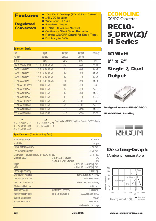
ECONOLINE
DC/DC-Converter
REC10S_DRW(Z)/ H Series
10 Watt 1” x 2” Single & Dual Output
Selection Guide
Part Number 1” x 2” REC10-xx3.3SRW/H REC10-xx05SRW/H REC10-xx12SRW/H REC10-xx15SRW/H REC10-xx24SRW/H REC10-xx3.3SRWZ/H REC10-xx05SRWZ/H REC10-xx12SRWZ/H REC10-xx15SRWZ/H REC10-xx3.3DRWZ/H REC10-xx05DRWZ/H REC10-xx12DRWZ/H REC10-xx15DRWZ/H 2:1 xx = 9-18Vin = 12 xx = 18-36Vin = 24 xx = 36-75Vin = 48 Input Voltage (VDC) 9-18, 18-36, 36-75 9-18, 18-36, 36-75 9-18, 18-36, 36-75 9-18, 18-36, 36-75 9-18, 18-36, 36-75 9-36, 18-75 9-36, 18-75 9-36, 18-75 9-36, 18-75 9-36, 18-75 9-36, 18-75 9-36, 18-75 9-36, 18-75 Output Voltage (VDC) 3.3 5 12 15 24 3.3 5 12 15 ±3.3 ±5 ±12 ±15 Output Current (mA) 2000 2000 830 670 420 2000 2000 830 670 ±1000 ±1000 ±416 ±333 (%) 74-76 80-81 81-84 82-84 81-84 74 77-80 81-82 80-82 74 77-80 81-82 80-82 Efficiency
CDMA BTS 4812T 简介

CDMA BTS 4812T 简介目录1CDMA BTS 4812T 基本介绍 (2)1.1信道处理器机架 (2)1.2信道处理器机架C-CCP的介绍 (2)1.2信道处理器机架 (3)1.2主要控制板卡功能简介 (3)1.3基站顶部的介绍 (8)2BTS基站上电前的准备 (12)2.1基站接地检查 (12)2.2基站上电检查 (12)2.3CSM 系统GPS的跟踪 (13)2.4Span检测 (15)1 CDMA BTS 4812T 基本介绍1.1 信道处理器机架信道处理器机架C-CCP 的介绍1) 信道处理器机架(C-CCP )中安装基站的各种控制板卡,如(图3-1)所示。
图3-1信道处理器机架中各种控制板卡的安装位置示意图2) 处理器机架图信道处理器机架主要由以下控制板卡:a) PS-1,PS-2 - 电源模块 b) GLI2 - 接口板 c) CIO - 输出输入合成板 d) CCD - 时钟处理板 e) HSO - 高稳晶振 f) AMR - 告警板 g) CSM - GPS 接收处理 h) MCC24 – 24路语音处理板 i) MCC8 - 8路语音处理板 j) BBX2 - 宽带收发处理板 k) Switch – 板卡切换控制 l) MPC - 话路预选控制器1.2信道处理器机架主要控制板卡功能简介1)GLI2的功能GLI2的功能相当于整个BTS的控制器。
它提供了话音和信令的路由,对信道处理器机架“C-CCP”中的所有板卡进行管理。
(1)GLI2提供了BTS与CBSC的SPAN的接口。
(2)GLI2提供了BTS与外部设备连接的网口(LAN A和LAN B)。
如LMF的接入端口。
(3)GLI2提供了一个MMI口,用操作系统中的Hyper Terminal可以接入。
且通过MMI,维护人员可以对GLI2和SPAN的各种状态进行监控和设置。
a)GLI2板卡上的指示灯状态及含义在GLI2有五个指示灯,一个“RESET”按钮和一个“MMI”接口。
48VSC4812BTS收集资料

· 双工器(Duplexers) · 接收滤波器(RX Site Filters)
4.1 -48 伏C-CCP 机 4.1 -48伏框C-CCP机框
4.1.1 MCC-24/MCC-8E 4.1.1 MCC-24/MCC-8E
(1) 支持的信道类型有同步信道、寻呼信道、接入信道、 业务信道;
4.04.0 -4-84伏8伏SSCCTTMM44881122T功T功能能模块模块
C-CCP 机框
· 多信道板 MCC-24 / MCC-8E(MCC = Multi-Channel CDMA Card)
· 宽带收发信板(BBX = Broad Band Transceiver) · 群线路接口板(GLI = Group Line Interface) · 组合输入/ 输出板(CIO = Combiner Input/Output) · 时钟同步管理板(CSM = Clock Synchronization Manager Card) · CDMA 时钟分配板(CCD = CDMA Clock Distribution) · 高稳晶振板(HSO = High Stability Oscillator) · 告警、监视、报告板(AMR = Alarm Monitoring and Reporting) · 多路耦合预选器板(MPC = Multicoupler/Preselector Card) · -48伏CCP电源板 · 切换板(SWITCH)
2.21.1 –4–84伏8伏SCSTCMT4M841821T2基T基站站各各部部件件分分布布图图
3.0 48伏SCTM4812T基站功能概述
3.0 -48伏SCTM4812T基站功能概述
· 发射路径 · 接收路径 · 机架内通信 · 站点间通信
REC3-1212SRWH4中文资料
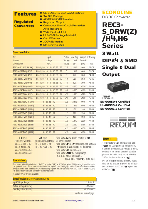
Notes :
1. If the options "/M" for metal case and "/SMD" for SMD pinout are combined, the maximum allowed isolation voltage is 2kVDC because of the shorter distances between pins and the metal case, so only available SMD-option in metal-case is "/H2". DIP-24 through-hole case and SMD-plastic case are not affected and offer the full isolation barriers of 4kVDC for "/H4" option and 6kVDC for "/H6".
3
}
Detailed Information see Application Notes chapter "MTBF"
120 100 80 60 50 40 20 0 -40
Safe Operating Area
0
25
50 75
100 85 105
125
Operating Temperature (°C)
Safe Operating Area
100 50 75 125 80 105 Operating Temperature (°C) 0 25
Output Power (%)
-55°C to +125°C 95% RH Non-Conductive Plastic 20°C/W for metal case 13g 1043 x 10 hours 186 x 103 hours
RP30-4812DEW中文资料
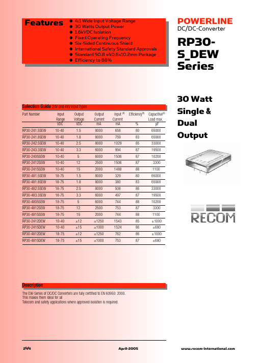
RP30-S_DEW Series
±1% ±10% 0% 10% of FL ±0.5% ±0.5% ±1% ±5% 60mVp-p 75mVp-p 100mVp-p 100mVp-p ±0.02%/°C, max. 300µS 1.5, 1.8, 2.5, 3.3V 5V 12V 15V 3.9V 6.2V 15V 18V 150% typ Hiccup, automatic recovery see „Selection Guide“ table 1.600VDC min. 109 Ω min. 1000pF max. 300kHz typ. EN60950 -40°C to +85°C(with derating) +100°C -55°C to +105°C Natural convection Natural convection with Heat Sink 115°C typ. 10°C/Watt 8.24°C/Watt MIL-STD-810D 10-55Hz, 2G, 30 Min. along X, Y and Z 5% to 95% RH Nickel-Coated copper Non-conductive black plastic Epoxy (UL94-V0) EN55022 EN55022 EN61000-4-2 EN61000-4-3 EN61000-4-4 EN61000-4-5 EN61000-4-6 Class A Class A Perf. Criteria 2 Perf. Criteria 2 Perf. Criteria 2 Perf. Criteria 2 Perf. Criteria 2 continued on next page
50 60 70
飞利浦 DVD播放机 说明书

48目錄語言代碼----------------------------------------------5介紹提供配件--------------------------------------------50清潔光碟--------------------------------------------50設置--------------------------------------------------50連接連接電視機-------------------------------------51-52使用複合視頻插孔(CVBS)...................51使用色差視頻插孔(Y Pb Pr).................51使用RF 調制器配件................................52連接電源線------------------------------------------52選項:連接至多通道接收器---------------------53A/V 功放具有杜比數碼或DTS 解碼功能....................................................................53選項: 連接立體聲系統----------------------------53立體聲有杜比環繞立體聲或左/右Audio In 的插孔....................................................53選項: 連接數碼AV 接收器----------------------54接收器有一個PCM 、杜比數碼 或MPEG 解碼器....................................................54選項:連接至HDMI 的插孔---------------------55使用HDMI(高解析度多媒體介面)插座..............................................................55選項:連接至一個可支持的USB 設備-------56使用USB 插口........................................56功能概覽前后面板--------------------------------------------57遙控器-----------------------------------------------58啟動步驟一:在遙控器裝入電池---------------------59使用遙控器操作本音響系統....................59步驟二:設定電視機-------------------------59-61設定逐行掃描功能(只適用於有逐行掃描電視機)..................................................60選擇對應電視機的制式...........................61步驟三:設置界面語言--------------------------62設定屏幕顯示語言..................................62設定聲音、字幕和碟片菜單語言. (62)光碟操作適合播放的媒體類別-----------------------------63地區編碼--------------------------------------------63播放光碟--------------------------------------------64基本播放控制---------------------------------------64影像播放操作方式(DVD/VCD/SVCD)-----65使用光碟目錄.........................................65放大........................................................65由最后停止的點,恢復播放....................65慢放........................................................65向前∕向后搜索......................................65OSD (在屏幕顯示) (DVD/VCD/SVCD)---66-68使用OSD 選單.......................................66選擇標題∕章節∕曲目...........................66時間搜索.................................................66聲音∕字幕.............................................67角度........................................................67瀏覽功能.................................................67重複播放模式.........................................68個章節∕曲目重複一個段落....................68OSD (在屏幕顯示) (Audio CD)-----------------68盤片時間∕曲目時間∕選擇曲目.............68重複........................................................68DVD 的特殊功能-----------------------------------69標題播放.................................................69改變聲音語言.........................................69多字幕功能.............................................69VCD 與SVCD 的特殊功能----------------------69對於播放控制(PBC).............................69播放DivX 光碟-------------------------------------70從支持的USB 設備播放圖片或音頻文件----71USB 設備的兼容性.................................71播放MP3/WMA/JPEG/Kodak 影像光碟-72-73基本操作.................................................72播放選擇.................................................72瀏覽功能(JPEG)..................................72圖像放大功能(JPEG)...........................73多角度效果播放功能(JPEG)................73同時播放MP3/WMA 音樂與JPEG 影像................................................................73卡拉OK 操作卡拉OK 光碟的播放------------------------------74基本操作.................................................74伴唱........................................................74卡拉OK..................................................74DVP5965K_93_CS(0608)212/21/06, 2:35 PM4849DVD 設定選單項目通用設定頁-------------------------------------75-76光碟收看鎖碼∕取消光碟收看鎖碼.........75降低機器顯示面板的亮度.......................75編程光碟曲目(不適用於CD/MP3/WMA/DivX).................................................75-76OSD 語言...............................................76睡眠........................................................76DivX(R) VOD 注冊碼..............................76音頻設定頁-------------------------------------77-79模擬輸出.................................................77數字音頻設定.........................................77聲音模式.................................................78揚聲器設定.............................................78CD 升頻..................................................78夜間模式啟動∕關閉...............................79視頻設定頁-------------------------------------79-82電視機制式.............................................79屏幕畫面比例.........................................80逐行掃描啟動∕關閉...............................80畫質設定.................................................81高解析度JPEG 影像模式.......................82HDMI 設定..............................................82初期設定頁-------------------------------------82-84聲音、字幕、碟片菜單語言....................82透過設定年齡控制播放...........................83PBC........................................................83MP3/JPEG 選單啟動∕關閉...................83變更密碼.................................................84設置DivX 字幕........................................84恢復原廠設定.........................................84聲音和音量控制設定揚聲器的聲道--------------------------------85故障指南---------------------------------------86-87產品規格--------------------------------------------88詞匯--------------------------------------------------89目錄DVP5965K_93_CS(0608)212/21/06, 2:35 PM4950提供配件複合視頻接線(黃色)音頻接線(白色、紅色)遙控器和兩枚電池介紹清潔光碟如要清潔光碟,使用具有微纖維的清潔軟布,由光碟的中心以直線方向抹至碟邊。
RECOM 电源 RSE 系列 2W 隔离 DC DC 转换器 产品说明书
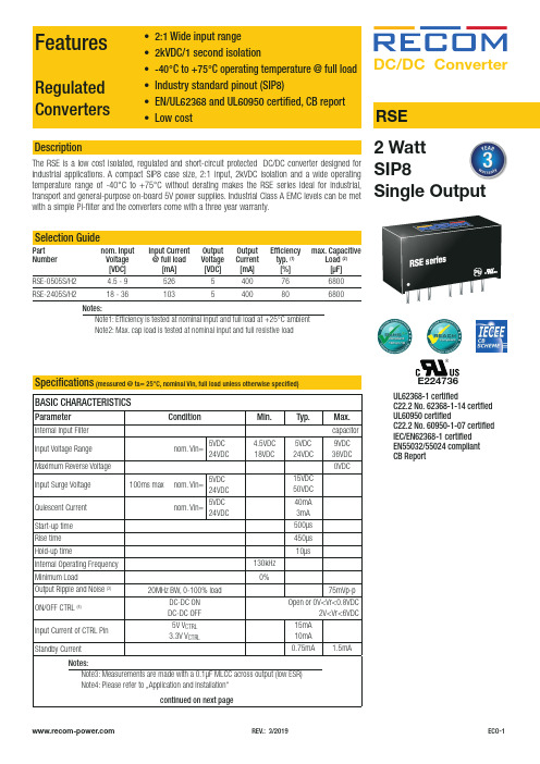
REV.: 3/2019ECO-1Regulated • 2:1 Wide input range • 2kVDC/1 Second isolation• -40°C To +75°C Operating temperature @ full load • Industry standard pinout (SIP8)• EN/UL62368 and UL60950 certified, CB report • Low cost RSEDescriptionThe RSE is a low cost isolated, regulated and short-circuit protected DC/DC converter designed forDC/DC Convert er2 WattE224736UL62368-1 certifiedC22.2 No. 62368-1-14 certfied UL60950 certifiedC22.2 No. 60950-1-07 certified IEC/EN62368-1 certified EN55032/55024 compliant CB ReportFeaturesConverters• 2:1 Wide input range • 2kVDC/1 second isolation -40°C to +75°C operating temperature @ full load • EN/UL62368 and UL60950 certified, CB report • Low costBASIC CHARACTERISTICSParameterCondition Min.Typ.Max.Internal Input Filter capacitor Input Voltage Range nom. Vin=5VDC 24VDC4.5VDC 18VDC5VDC 24VDC9VDC 36VDC Maximum Reverse Voltage 0VDCInput Surge Voltage 100ms max nom. Vin=5VDC 24VDC 15VDC 50VDC Quiescent Current nom. Vin=5VDC 24VDC40mA 3mA Start-up time 500µs Rise time 450µs Hold-up time10µsInternal Operating Frequency 130kHz Minimum Load0%Output Ripple and Noise (3)20MHz BW, 0-100% load75mVp-pON/OFF CTRL (4)DC-DC ON DC-DC OFF Open or 0V<Vr<0.8VDC2V<Vr<6VDC Input Current of CTRL Pin 5V V CTRL 3.3V V CTRL15mA 10mA Standby Current0.75mA1.5mAcontinued on next pageNotes:Note3: Measurements are made with a 0.1µF MLCC across output (low ESR) Note4: Please refer to …Application and Installation“Specifications (measured @ ta= 25°C, nominal Vin, full load unless otherwise specified)REV.: 3/2019ECO-2Specifications (measured @ Ta= 25°C, nominal Vin, full load unless otherwise specified)PROTECTIONSParameterTypeValueShort Circuit Protection (SCP)below 100m Wcontinuous, auto recoveryIsolation Voltage (5)I/P to O/Ptested for 1 second2kVDC Isolation Resistance 1G W min.Isolation Capacitance 100pF max.Insulation Gradefunctionalcontinued on next pageREGULATIONSParameterConditionValueOutput Accuracy 0-100% load ±2.0% max.Line Regulation low line to high line, full load±0.2% max.Load Regulation0% to 100% load±0.5% max.RSE-0505S/H2RSE-2405S/H2Accuracy vs. LoadA c c u r a c y [%]Output Current [A]000.20.10.30.40.50.60.10.20.30.4A c c u r a c y [%]Output Current [A]000.10.20.30.40.50.10.20.30.4REV.: 3/2019ECO-3Specifications (measured @ Ta= 25°C, nominal Vin, full load unless otherwise specified)ENVIRONMENTALParameterConditionValueOperating Temperature Range without derating (see graph)-40°C to +75°CMaximum Case Temperature +105°C Temperature Coefficient ±0.05%/°COperating Altitude 5000mOperating Humidity non-condensing5% - 95% RH max.Pollution Degree PD2MTBF according to MIL-HDBK-217F, G.B.+25°C +75°C2289 x 103 hours 781 x 103 hours VibrationMIL-STD 202G100806040200-4005075100150O u t p u t P o w e r [%]Ambient Temperature [°C]Derating Graph(@ Chamber and natural convection 0.1m/s)SAFETY AND CERTIFICATIONSCertificate Type (Safety)Report / File NumberStandard Information Technology Equipment, General Requirements for Safety E224736-A48UL60950-1, 2nd Edition, 2014CSA C22.2 No. 60950-1-07, 2nd Ed. 2014Audio/Video, information and communication technology equipment - Safety requirementsUL62368-1, 2nd Edition, 2014CSA C22.2 Nr. 62368-1-14, 2nd Ed. 2014Audio/Video, information and communication technology equipment - Safety requirements (CB Scheme)L0339m37-CB-1-B1IEC/EN62368-1, 2nd Edition, 2014RoHS 2+RoHS 2011/65/EU + AM2015/863continued on next pageSpecifications(measured @ Ta= 25°C, nominal Vin, full load unless otherwise specified)DIMENSION and PHYSICAL CHARACTERISTICSParameter Type ValueMaterialcasepottingPCBnon-conductive black plastic (UL94V-0)epoxy (UL94V-0)FR4 (UL94V-0)Dimension (LxWxH)21.8 x 9.2 x 11.1mm Weight 4.7g typ.continued on next pageC3 REV.: 3/2019ECO-4Specifications(measured @ Ta= 25°C, nominal Vin, full load unless otherwise specified)PACKAGING INFORMATIONPackaging Dimension (LxWxH)tube520.0 x 11.2 x 18.2mm Packaging Quantity22pcs Storage Temperature Range-55°C to +125°C Storage Humidity non-condensing5% - 95% RH max.The product information and specifications may be subject to changes even without prior written notice.The product has been designed for various applications; its suitability lies in the responsibility of each customer. The products are not authorized for use in safety-critical applications without RECOM’s explicit written consent. A safety-critical application is an application where a failure may reasonably be expected to endanger or cause loss of life, inflict bodily harm or damage property. The applicant shall indemnify and hold harmless RECOM, its affiliated companies and its representatives against any damage claims in connection with the unauthorizeduse of RECOM products in such safety-critical applications. REV.: 3/2019ECO-5。
4812说明书
简介谢谢您购买绿扬牌YB4812型晶体管特性图示仪。
为保证正确利用,请在利用前认真阅读此说明书.阅毕,请将说明书保留好。
该图示仪依照严格的质量操纵标准生产,元器件进行了全面的挑选老化。
售后效劳:若是显现任何故障,请与咱们的销售部或各维修点联系,以取得快捷而有效的售后效劳。
注意:该仪器必需在规定的工作环境中利用,才能保证其处于最正确工作状态。
警示:电源插头应有接地爱惜,改换保险丝时应断开输入电源。
非专业技术人员请勿打开盖板。
1.概述YB4812型晶体管特性图示仪是一种用于测量各类半导体管特性曲线和静态参数的测量仪器。
本仪器是新一代便携式图示仪,整机采纳新颖电路设计技术,除具有一般图示仪的功能外,还具有外形轻巧、操作简便、性能稳固靠得住、性价比高的特点,能知足大部份半导体器件的测试要求。
适合于工厂生产线、大专院校、仪器修理业等领域。
2.要紧技术指标Y轴系统集电极电流范围(Ic):10μA/div~div,分14档,误差不超过±5%。
扩展×10,误差不超过±10%。
X轴系统集电极电压范围(Vc):div~50V/div,分10档,误差不超过±5%。
基极电压范围(Vbe):~div,分4档,误差不超过±5%。
阶梯信号阶梯电流范围:5μA/div~10mA/div,分11档,误差不超过±5%。
阶梯电压范围:~,分4档,误差不超过±5%。
每簇级数:0~10级持续可调。
串联电阻:0、10kΩ,误差不超过±10%。
集电极扫描电源峰值电压:0~50V、0~500V持续可调。
电流容量:0~50V 2A;0~500V 500mA。
功耗限制电阻:约0~100kΩ持续可调。
容性电流:500V时小于5μA。
其他示波管:15SJ118Y-14(内)。
外型尺寸:430mm×320mm×150mm (D×B×H)。
Richtek RT4812高效增压转换器数据手册说明书

RT4812Copyright © 2022 Richtek Technology Corporation. All rights reserved. is a registered trademark of Richtek Technology Corporation.High Efficiency Boost ConverterGeneral DescriptionThe RT4812 allows systems to take advantage of new battery chemistries that can supply significant energy when the battery voltage is lower than the required voltage for system power ICs. By combining built-in power transistors, synchronous rectification, and low supply current; this IC provides a compact solution for systems using advanced Li-Ion battery chemistries. The RT4812 is a boost regulator designed to provide a minimum output voltage from a single-cell Li-Ion battery, even when the battery voltage is below system minimum. In boost mode, output voltage regulation is guaranteed to a maximum load current of 2.1A. Quiescent current in Shutdown Mode is less than 1 A, which maximizes battery life.Ordering InformationRT4812G : Green (Halogen Free and Pb Free)Note :Richtek products are :④RoHS compliant and compatible with the current requirements of IPC/JEDEC J-STD-020.④Suitable for use in SnPb or Pb-free soldering processes.Features●CMCOT Topology and Small Output Ripple when VIN close VOUT Voltage●Operates from a Single Li-ion Cell : 1.8V to 5.5V ●Adjustable Output Voltage : 1.8V to 5.5V ●PSM Operation ●Up to 96% Efficiency ●Boost Current Limit●Output Over-Voltage Protection●Pin Adjustable Average Output Current Limit Threshold (2 Levels)●Internal Compensation ●Output Discharge ●Output Short Protection ●True Load DisconnectApplications●Single-Cell Li-Ion, LiFePO4 Smart-Phones ●Portable EquipmentMarking Information0L= : Product Code DNN : Date Code0L=DNNSimplified Application CircuitGNDSWVOUTENL1C1VINC2C3FBRT4812R1R2V OUTV ILIMH/LR3RT4812Pin Configuration(TOP VIEW)V I NV O U TP G N DI L I MS WG N DF BE N5346827TSOT-23-8 (FC)Functional Pin DescriptionPin No. Pin Name Pin Function1 VIN Power input. Input capacitor C IN must be placed as close to IC as possible.2 FB Voltage feedback.3 VOUT Boost converter output.4 PGND Power ground.5 GND Analog ground.6 SW Switching node.7 EN Enable input (1 enabled, 0 disabled), must not be floating. 8ILIMAverage output current limit control pin. (H/L)Functional Block DiagramGate DRVAMPPWM CTRLVREFDigital CTRLOSCOTP UVLOOCP+-SW ControlRT4812Copyright © 2022 Richtek Technology Corporation. All rights reserved. is a registered trademark of Richtek Technology Corporation.OperationThe RT4812 combined built-in power transistors, synchronous rectification, and low supply current, it provides a compact solution for system using advanced Li-Ion battery chemistries.In boost mode, output voltage regulation is guaranteed to a maximum load current of 2.1A. Quiescent current in Shutdown mode is less than 1μA, which maximizes battery life. Mode Depiction Condition LINLIN 1 Linear startup 1 V IN > V OUT LIN 2Linear startup 2 V IN > V OUT Soft-Start Boost soft-start V OUT < V OUT(MIN) Boost Boost modeV OUT = V OUT(MIN)LIN StateWhen V IN is rising, it enters the LIN State. There are two parts for the LIN state. It provides maximum current for 1A to charge the C OUT in LIN1, and the other one is for 3A in LIN2. By the way, the EN is pulled high and V IN > UVLO.As the figure shown, if the timeout is over the specification, it will enter the Fault mode.EN = 1, Vin > UVLOLIN 1Soft-StartLIN 2Fault StateBoost modeTimeout < 512μsTimeout > 512μsTimeout > 1024μs Timeout < 1024μsFigure 1. RT4812 State ChartStartup and Shutdown StateWhen V IN is rising and through the LIN state, it will enter the Startup state. If EN is pulled low, any function is turned-off in shutdown mode. Soft-Start StateIt starts to switch in Soft-start state. After the LIN state, output voltage is rising with the internal reference voltage. Fault StateAs the Figure 1 shown, it will enter to the Fault state as below,The timeout of LIN2 is over the 1024μs.It will be the high impedance between the input and output when the fault is triggered. A restart will be start after 20ms. OCPThe converter senses the current signal when the high-side P-MOSFET turns on. As a result, the OCP is cycle-by-cycle current limitation. If the OCP occurs, the converter holds off the next on pulse until inductor current drops below the OCP limit. OTPThe converter has an over-temperature protection. When the junction temperature is higher than the thermal shutdown rising threshold, the system will be latched and the output voltage will no longer beregulated until the junction temperature drops under the falling threshold.Input Voltage POR (Power-On Reset)The RT4812 is implemented POR function. Power-on reset (POR) function is used to reset IC's status todefault. POR function is activated, when VIN is dropped and it should meet POR requirements. POR function may fail if VIN pattern are not meet POR event requirement.POR event requirements are listed below, refer to Figure 2 for the pattern.RT48121. VIN_min < 0.5V2. Width > 20μs3. SR_rising < 1V/μsVINWidthSR_falling SR_risingVIN_minVIN : Input voltageSR_falling : Slew rate for input voltage dropSR_rising : Slew rate for input voltage resumeWidth : Duration of input voltage dropVIN_min : Minimum voltageFigure 2. POR Pattern IllustrationRT4812Copyright © 2022 Richtek Technology Corporation. All rights reserved. is a registered trademark of Richtek Technology Corporation.Absolute Maximum Ratings (Note 1)● VIN, FB, ILIM, EN, SW to GND ---------------------------------------------------------------------------------- -0.2V to 6V ● VOUT to GND ------------------------------------------------------------------------------------------------------- 6.2V ● Power Dissipation, PD @ TA = 25︒C● TSOT-23-8 (FC) ----------------------------------------------------------------------------------------------------- 1.78W ●Package Thermal Resistance (Note 2)TSOT-23-8 (FC), θJA ----------------------------------------------------------------------------------------------- 56︒C/WTSOT-23-8 (FC), θJC ----------------------------------------------------------------------------------------------- 28︒C/W● Lead Temperature (Soldering, 10sec.) ------------------------------------------------------------------------- 260︒C● Junction Temperature -------------------------------------------------------------------------------------------- -65︒C to 150︒C ● Storage Temperature Range ------------------------------------------------------------------------------------- -65︒C to 150︒C ●ESD Susceptibility (Note 3)HBM (Human Body Model) -------------------------------------------------------------------------------------- 2kVRecommended Operating Conditions (Note 4)● Input Voltage Range ---------------------------------------------------------------------------------------------- 1.8V to 5.5V ● Output Voltage Range --------------------------------------------------------------------------------------------- 1.8V to 5.5V ● Junction Temperature (T J ) Range ------------------------------------------------------------------------------ -40︒C to 125︒C ●Ambient Temperature (T A ) Range ------------------------------------------------------------------------------ -40︒C to 85︒CElectrical CharacteristicsParameterSymbol Test ConditionsMin Typ Max Unit Supply Voltage V IN V IN < V OUT - 0.2V 1.8 -- 5.5 V Output Voltage V OUT V IN < V OUT - 0.2V 1.8 -- 5.5 V Under-Voltage Lockout Rising Threshold UVLO _RISE 1.5 1.65 1.8 V Under-Voltage Lockout Falling Threshold UVLO _Falling1.3 1.55 1.7 V FB VoltageV FB Force PWM0.495 0.5 0.505 V Regulated DC V OUT Voltage V OUT 1.8 ≤ V IN ≤ V OUT - 0.2V I OUT = 0mA (PSM) -2 -- 4 % Shutdown Current I SHDNEN = 0V-- 0.1 1 μA Quiescent CurrentClose loop, no loadFB = 3V, non-switching current -- 90 -- μA Pre-charge Current Ipre-- 1 -- A Switching Frequencyf SWV OUT - V IN > 1V -- 0.5 -- MHz Average Output Current Limit I LIM I LIM = L 1 -- -- A I LIM = H 2.1 -- -- High-Side Switch Ron V IN = 5V -- 45 -- m Ω Low-Side Switch RonV IN = 5V--30--m ΩRT4812Parameter Symbol Test Conditions Min Typ Max Unit FB Pin Input Leakage I FB-1 -- 1 μA Leakage of SW I SW All switch off -- -- 5 μALine Regulation ∆V OUT, LINE V IN = 2.7V to 4.5V, V OUT = 5V,I OUT = 1500mA-2 -- 2 %Load Regulation ∆V OUT, LOAD CCM, I OUT< 2A, V IN = 3.6V,V OUT = 5V-1.5 -- 1.5 %Output Over VoltageProtectionV OVP 5.8 6 6.2 V EN Input Low Voltage V IL-- -- 0.4 V EN Input High Voltage V IH 1.2 -- -- V EN Sink Current -- 0.1 1 μA Thermal Shutdown T SD-- 160 -- ︒C Thermal ShutdownHysteresis∆T SD -- 30 -- ︒CNote 1. Stresses beyond those listed under “Absolute Maximum Ratings” may cause permanent damage to the device. These are stress ratings only, and functional operation of the device at these or any other conditions beyond those indicated in the operational sections of the specifications is not implied. Exposure to absolute maximum rating conditions may affect device reliability.Note 2. θJA is measured at T A= 25︒C on a two-layer Richtek Evaluation Board.Note 3. Devices are ESD sensitive. Handling precautions are recommended.Note 4. The device is not guaranteed to function outside its operating conditions.RT4812Copyright © 2022 Richtek Technology Corporation. All rights reserved. is a registered trademark of Richtek Technology Corporation.Typical Application CircuitGND SWVOUTPGND EN L1C1VINC2C3FBRT4812R1R2V OUT1234567V ILIM822μF1μF100k909k 22μF x 2R3100kRT4812Typical Operating CharacteristicsEfficiency vs. Output Current01020304050607080901000400800120016002000Output Current (mA)E f f i c i e n c y (%)V IN = 4.2V V IN = 3.6VV IN = 2.5V V IN = 1.8V V OUT = 5V, L = 1.5μH (TDK SPM6530),R1 = 45.3k, R2 = 4.99k, C OUT = 22μF x 2Efficiency vs. Output Current01020304050607080901000400800120016002000Output Current (mA)E f f i c i e n c y (%)V OUT = 3.6V, L = 1.5μH (TDK SPM6530), R1 = 45.3k, R2 = 7.3k, C OUT = 22μF x 2V IN = 2.5V V IN = 1.8VEfficiency vs. Outout Current010203040506070809010004008001200160020002400Outout Current (mA)E f f i c i e n c y (%)V IN = 4.2V V IN = 3.7VV IN = 3.3V V IN = 2.5V V IN = 1.8V V OUT = 5V, L = 1.5μH (TDK SPM6530), R1 = 909k,R2 = 100k, C OUT = 22μF x 2Efficiency vs. Output Current010203040506070809010004008001200160020002400Output Current (mA)E f f i c i e n c y (%)V IN = 2.5V V IN = 1.8VV OUT = 3.6V, L = 1.5μH (TDK SPM6530), R1 = 909k,R2 = 146.6k, C OUT = 22μF x 2Load Current vs. Output Voltage0.00.51.01.52.02.54.04.24.44.64.85.0Output Voltage (V)L o a d C u r r e n t (A )I LIM = HI LIM = LShutdown Current vs. Temperature0.00.20.40.60.81.01.21.41.61.8-40-1510356085Temperature (°C)S h u t d o w n C u r r e n t (μA )V IN = 5.5V V IN = 3.6VRT4812Copyright © 2022 Richtek Technology Corporation. All rights reserved. is a registered trademark of Richtek Technology Corporation.V BAT = 2.5V, V OUT = 5V, I OUT = 0mAL = 1.5μH, C OUT = 22μF x 2SW (2V/Div)V OUT_ac (50mV/Div)Output Voltage RippleTime (10μs/Div)SW (2V/Div)L = 1.5μH, C OUT = 22μF x 2V BAT = 2.5V, V OUT = 5V, I OUT = 1000mAV OUT_ac (20mV/Div)Output Voltage RippleTime (1μs/Div)SW (2V/Div)V OUT_ac (50mV/Div)V BAT = 3.6V, V OUT = 5V, I OUT = 0mAL = 1.5μH, C OUT = 22μF x 2Output Voltage RippleTime (10μs/Div)SW (2V/Div)V OUT_ac (20mV/Div)Time (1μs/Div)V BAT = 3.6V, V OUT = 5V, I OUT = 1000mAL = 1.5μH, C OUT = 22μF x 2Output Voltage RippleSW (2V/Div)V OUT_ac (50mV/Div)V BAT = 4.2V, V OUT = 5V, I OUT = 0mAL = 1.5μH, C OUT = 22μF x 2Output Voltage RippleTime (10μs/Div)SW (2V/Div)V OUT_ac (20mV/Div)V BAT = 4.2V, V OUT = 5V, I OUT = 1000mA,L = 1.5μH, C OUT = 22μF x 2Output Voltage RippleTime (1μs/Div)RT4812I OUT (1A/Div)V OUT_ac (200mV/Div)Time (500μs/Div)Load Transient ResponseV BAT = 2.5V, V OUT = 5V,I OUT = 1000mA to 2000mA L = 1.5μH, C OUT = 22μF x 2I OUT (1A/Div)V OUT_ac (200mV/Div)V BAT = 3.7V, V OUT = 5V,I OUT = 1000mA to 2000mA L = 1.5μH, C OUT = 22μF x 2Time (500μs/Div)Load Transient ResponseI OUT (1A/Div)V OUT_ac (200mV/Diiv)V BAT = 4.2V, V OUT = 5V,I OUT = 1000mA to 2000mA L = 1.5μH, C OUT = 22μF x 2Load Transient ResponseTime (500μs/Div)RT4812Copyright © 2022 Richtek Technology Corporation. All rights reserved. is a registered trademark of Richtek Technology Corporation.Application InformationEnableThe device can be enabled or disabled by the EN pin. When the EN pin is higher than the threshold of logic-high, the device starts operating with soft-start. Once the EN pin is set at low, the device will be shut down. In shutdown mode, the converter stops switching, internal control circuitry is turned off, and the load is disconnected from the input. This also means that the output voltage can drop below the input voltage during shutdown. Soft-Start StateAfter the successful completion of the LIN state (V OUT ≥ V IN = 300mV), the regulator begins switching with boost valley-current limited value 3500mA.During Soft-Start state, V OUT is ramped up by Boost internal loop. If V OUT fails to reach target value during the Soft-Start period for more than 2ms, a fault condition is declared. Output Voltage SettingThe output voltage is adjustable by an external resistive divider. The resistive divider must be connected between VOUT, FB and GND. When the output voltage is regulated properly, the typical value of the voltage at the FB pin is 500mV. Output voltage can be calculated by equation as below : OUT FB V R1R21V ⎛⎫=⨯- ⎪⎝⎭Power Save ModePSM is the way to improve efficiency at light load. When the output voltage is lower than a set threshold voltage, the converter will operate in PSM.It raises the output voltage with several pulses until the loop exits PSM. Under-Voltage LockoutThe under-voltage lockout circuit prevents the device from operating incorrectly at low input voltages. It prevents the converter from turning on the power switches under undefined conditions and prevents the battery from deep discharge. VIN voltage must be greater than 1.65V to enable the converter. During operation, if VIN voltage drops below 1.55V, the converter is disabled and waiting internal IC default parameter value ready until the supply exceeds the UVLO rising threshold. The RT4812 automatically restarts if the input voltage recovers to the input voltage UVLO high level. Thermal ShutdownThe device has a built-in temperature sensor which monitors the internal junction temperature. If the temperature exceeds the threshold, the device stops operating. As soon as the IC temperature has decreased below the threshold with a hysteresis, it starts operating again. The built-in hysteresis is designed to avoid unstable operation at IC temperatures near the over temperature threshold. Inductor SelectionThe recommended nominal inductance value is 1.5μHIt is recommended to use inductor with dc saturation current ≥ 5000mAManufacturerSeries Dimensions (in mm)Saturation Current (mA)TDK SPM6530T 7.1 x 6.5 x 3.0 11500 Taiyo YudenNRS5040T5.15 x 5.15 x 4.26400RT4812Input Capacitor SelectionAt least a 22μF and the rate voltage is 16V for DC bias input capacitor is recommended to improve transient behavior of the regulator and EMI behavior of the total power supply circuit for SW. And at least a 1μF ceramic capacitor placed as close as possible to the VIN and GND pins of the IC is recommended. Output Capacitor SelectionAt least 22μF x 2 capacitors is recommended to improve V OUT ripple.Output voltage ripple is inversely proportional toC OUT .Output capacitor is selected according to output ripple which is calculated as : LOADRIPPLE(P P)ON OUT IN ON SW SW OUT INLOAD OUT SW OUT RIPPLE(P P)SW SWIV t C andV t t D t 1V therefore :VI C t 1V V and 1t f --=⨯⎛⎫=⨯=⨯- ⎪⎝⎭⎛⎫=⨯-⨯⎪⎝⎭=The maximum V RIPPLE occurs at minimum input voltage and maximum output load.Output Discharge FunctionWith the EN pin set to low, the VOUT pin is internally connected to GND for 10ms by an internal discharge N-MOSFET switch. After the 10ms, IC will be true-shut down.This feature prevents residual charge voltages on capacitor connected to VOUT pins, which may impact proper power up of the system. Valley Current LimitThe RT4812 employs a valley-current limit detection scheme to sense inductor current during the off-time. When the loading current is increased such that the loading is above the valley current limit threshold, the off-time is increased until the current is decreased to valley-current threshold. Next on-time begins after current is decreased to valley-current threshold. On-time is decided by (V OUT - V IN ) / V OUT ratio. The output voltage decreases when further loading current increase. The current limit function is implemented by the scheme, refer to Figure 3. Average Output Current LimitThe RT4812 features the average output current limit to protect the output terminal. When the load current is over the limit, output current will be clamped.Valley Current LimitI IN (DC)∆I LInductor CurrentV D IN I = L L f∆⨯fI IN (DC)Figure 3. Inductor Currents In Current Limit OperationTable 2. List of CapacitorReferenceQty. Part Number Description Package Manufacturer CIN 1 GRM21BR61C226ME44 22μF / 16V / X5R 0805 MuRata COUT2GRM21BR61C226ME4422μF / 16V / X5R0805MuRataRT4812Copyright © 2022 Richtek Technology Corporation. All rights reserved. is a registered trademark of Richtek Technology Corporation.Thermal ConsiderationsFor continuous operation, do not exceed absolute maximum junction temperature. The maximum powerdissipation depends on the thermal resistance of the IC package, PCB layout, rate of surrounding airflow, and difference between junction and ambient temperature. The maximum power dissipation can be calculated by the following formula : P D(MAX) = (T J(MAX) - T A ) / θJAwhere T J(MAX) is the maximum junction temperature, T A is the ambient temperature, and θJA is the junction to ambient thermal resistance.For recommended operating condition specifications, the maximum junction temperature is 125︒C. The junction to ambient thermal resistance, θJA , is layout dependent. For TSOT-23-8 (FC) package, the thermal resistance, θJA , is 56︒C/W on a standard two-layer EVB test board. The maximum power dissipation at T A = 25︒C can be calculated by the following formula :P D(MAX) = (125︒C - 25︒C) / (56︒C/W) = 1.78W for TSOT-23-8 (FC) packageThe maximum power dissipation depends on the operating ambient temperature for fixed T J(MAX) and thermal resistance, θJA . The derating curve in Figure 4 allows the designer to see the effect of rising ambient temperature on the maximum power dissipation.0.00.40.81.21.62.0255075100125Ambient Temperature (°C)M a x i m u m P o w e r D i s s i p a t i o n (W )Two-Layer PCBFigure 4. Derating Curve of Maximum PowerDissipationLayout ConsiderationThe PCB layout is an important step to maintain the high performance of the RT4812.Both the high current and the fast switching nodes demand full attention to the PCB layout to save the robustness of the RT4812 through the PCB layout. Improper layout might show the symptoms of poor line or load regulation, ground and output voltage shifts, stability issues, unsatisfying EMI behavior or worsened efficiency. For the best performance of the RT4812, the following PCB layout guidelines must be strictly followed.④Input/Output capacitors must be placed as close as possible to the Input/Output pins.④SW should be connected to Inductor by wide and short trace, keep sensitive components away from this trace.④The feedback divider should be placed as close as possible to the FB pin.RT4812VoutVinGNDC o u tC i nC o u tL Figure 5. PCB Layout GuideRT4812Copyright © 2022 Richtek Technology Corporation. All rights reserved.is a registered trademark of Richtek Technology Corporation.Outline DimensionSymbol Dimensions In MillimetersDimensions In Inches Min Max Min Max A 0.700 1.000 0.028 0.039 A1 0.000 0.100 0.000 0.004 B 1.397 1.803 0.055 0.071 b 0.220 0.380 0.009 0.015 C 2.591 3.000 0.102 0.118 D 2.692 3.099 0.106 0.122 e 0.585 0.715 0.023 0.028 H 0.080 0.254 0.003 0.010 L0.3000.6100.0120.024TSOT-23-8 (FC) Surface Mount PackageRichtek Technology Corporation14F, No. 8, Tai Yuen 1st Street, Chupei City Hsinchu, Taiwan, R.O.C. Tel: (8863)5526789Richtek products are sold by description only. Richtek reserves the right to change the circuitry and/or specifications without notice at any time. Customers should obtain the latest relevant information and data sheets before placing orders and should verify that such information is current and complete. Richtek cannot assume responsibility for use of any circuitry other than circuitry entirely embodied in a Richtek product. Information furnished by Richtek is believed to be accurate and reliable. However, no responsibility is assumed by Richtek or its subsidiaries for its use; nor for any infringements of patents or other rights of third parties which may result from its use. No license is granted by implication or otherwise under any patent or patent rights of Richtek or its subsidiaries.。
海哥尔德电子产品简介说明书

APRIL 2013Quick-Refere nce GuideLAPTOP, DESKTO P AND VIDEO STORAGE DRIVESSeagate Partner Program MembersVisit the Sales Tools section to access the latestproduct roadmap, end-of-life schedule and product information. DistributorsEMEA SPP Support00-800-6890-8282US Sales Support1-800-SEAGATE or 1-405-324-4700Visit for more information or call 1-800-SEAGATE (1-800-732-4283) © 2013 Seagate Technology LLC. All rights reserved. Printed in USA. Seagate, Seagate Technology and the Wave logo are registered trademarks of Seagate Technology LLC in the United States and/or other countries. Barracuda, G-Force Protection, Momentus, Pipeline HD, SmartAlign and SV35 Series are either trademarks or registered trademarks of Seagate Technology LLC or one of its affiliated companies in the United States and/or other countries. The FIPS logo is a certification mark of NIST, which does not imply product endorsement by NIST, the U.S., or Canadian governments. All other trademarks or registered trademarks are the property of their respective owners. When referring to drive capacity, one gigabyte, or GB, equals one billion bytes and one terabyte, or TB, equals one trillion bytes. Your computer’s operating system may use a different standard of measurement and report a lower capacity. In addition, some of the listed capacity is used for formatting and other functions, and thus will not be available for data storage. Actual data rates may vary depending on operating environment and other factors. The export or re-export of hardware or software containing encryption may be regulated by the US Department of Commerce, Bureau of Industry and Security (for more information go to ). Seagate reserves the right to change, without notice, product offerings or specifications. QR502.15-1304GB, April 2013APRIL 2013Quick-Reference GuideLAPTOP, DESKTOP AND VIDEO STORAGE DRIVESNew Seagate Model Number KeyDesktop, laptop and video storageST 500 DX 001BRANdCAPACiTySegMeNTATTRiBuTeS2 letters ST= Seagate MX= Maxtor2 to 4 digits 80 = 80GB 500 = 500GB 1500 = 1,500GB Capacities>9,999GB: 10 = 10TB 15 = 15TB2 lettersDX = Desktop Premium DM = Mainstream DL = Entry LevelLX = Laptop Premium LM = Laptop Mainstream LT = Laptop Thin VX = Surveillance VM = DVR VT = DVR Thin3 digits, non-intelligent Varies for:Z-height Form Factor RPM Cache Interface SED, FIPS Drop Sensor Interface SpeedView a brief training presentation on how our model numbering format has changed at /seagate/ModelNumber 1 One gigabyte, or GB, equals one billion bytes; and one terabyte, or TB, equals one trillion bytes when referring to drive capacity.2See FIPS 140-2 Level 2 Certificate at /groups/STM/cmvp/documents/140-1/1401vend.htm.37mm z-height expanded to 9.5mm enables compatibility with standard laptop chassis.4Advanced Format 4K sector drive with SmartAlign ™ technology resolves misalignment conditions.5Seagate makes this drive in both 4K and 512-byte sectors. SmartAlign technology is included on 4K sector drives. Both drives are functionally and physically equivalent.6Formerly Barracuda ®drive。
绿色机器人科技模板

续时而生
LOGO-R系列
LOGO
云系列
产品功能:高亮照明灯,具有照明功能外观简洁,小巧,方便携带多个保护电子电路,保证设备的安全LED电量指标,电量随手掌握
产品参数:○ 型 号:R400/R600/R800/R1000○ 电 芯:国标锂离子○ 输 入:USB 5V / 1A○ 输 出:USB 5V / 1A○ 容 量:4400mAh/6600mAh /8800mAh/10000mAh
绿色机器人模板
高端科技来袭
R系列移动电源
2024新品解析
L心编制而成的,希望大家下载后,能够帮助大家解决实际问题。PPT课件下载后可定制修改,请根据实际需要进行调整和使用,谢谢!
本编为大家提供各种类型的PPT课件,如数学课件、语文课件、英语课件、地理课件、历史课件、政治课件、化学课件、物理课件等等,想了解不同课件格式和写法,敬请下载!
Moreover, our store provides various types of classic sample essays, such as contract agreements, documentary evidence, planning plans, summary reports, party and youth organization materials, reading notes, post reading reflections, essay encyclopedias, lesson plan materials, other sample essays, etc. If you want to learn about different formats and writing methods of sample essays, please stay tuned!
Whelen 电源系统用户指南说明书
©1998 Whelen Engineering Company Inc. Form No.13378B (092199)For warranty information regarding this product, visit /warranty•Proper installation of this product requires the installer to have a good understanding of automotive electronics, systems and procedures.•Whelen Engineering requires the use of waterproof butt splices and/or connectors if that connector could be exposed to moisture.•Any holes, either created or utilized by this product, should be made both air- and watertight using a sealant recommended by your vehicle manufacturer.•Failure to use specified installation parts and/or hardware will void the product warranty.•If mounting this product requires drilling holes, the installer MUST be sure that no vehicle components or other vital parts could be damaged by the drilling process. Check both sides of the mounting surface before drilling begins. Also de-burr the holes and remove any metal shards or remnants. Install grommets into all wire passage holes.•If this manual states that this product may be mounted with suction cups, magnets, tape or Velcro®, clean the mounting surface with a 50/50 mix of isopropyl alcohol and water and dry thoroughly.•Do not install this product or route any wires in the deployment area of your air bag. Equipment mounted or located in the air bag deployment area will damage or reduce the effectiveness of the air bag, or become a projectile that could cause serious personal injury or death. Refer to your vehicle owner’s manual for the air bag deployment area. The User/Installer assumes full responsibility to determine proper mounting location, based on providing ultimate safety to all passengers inside the vehicle.•For this product to operate at optimum efficiency, a good electrical connection to chassis ground must be made. The recommendedprocedure requires the product ground wire to be connected directly to the NEGATIVE (-) battery post (this does not include products that use cigar power cords).•If this product uses a remote device for activation or control, make sure that this device is located in an area that allows both the vehicle and the device to be operated safely in any driving condition.•Do not attempt to activate or control this device in a hazardous driving situation.•This product contains either strobe light(s), halogen light(s), high-intensity LEDs or a combination of these lights. Do not stare directly into these lights. Momentary blindness and/or eye damage could result.•Use only soap and water to clean the outer lens. Use of other chemicals could result in premature lens cracking (crazing) and discoloration. Lenses in this condition have significantly reduced effectiveness and should be replaced immediately. Inspect and operate this product regularly to confirm its proper operation and mounting condition. Do not use a pressure washer to clean this product.•It is recommended that these instructions be stored in a safe place and referred to when performing maintenance and/or reinstallation of this product.•FAILURE TO FOLLOW THESE SAFETY PRECAUTIONS AND INSTRUCTIONS COULD RESULT IN DAMAGE TO THE PRODUCT OR VEHICLE AND/OR SERIOUS INJURY TO YOU AND YOUR PASSENGERS!A u t o m o t i v e : Warnings to InstallersWhelen’s emergency vehicle warning devices must be properly mounted and wired in order to be effective and safe. Read and follow all of Whelen’s written instructions when installing or using this device. Emergency vehicles are often operated under high speed stressful conditions which must be accounted for when installing all emergency warning devices. Controls should be placed within convenient reach of the operator so that they can operate the system without taking their eyes off the roadway. Emergency warning devices can require high electrical voltages and/or currents. Properly protect and use caution around live electrical connections.Grounding or shorting of electrical connections can cause high current arcing, which can cause personal injury and/or vehicle damage, including fire. Many electronic devices used in emergency vehicles can create or be affected by electromagnetic interference. Therefore, after installation of any electronic device it is necessary to test all electronic equipment simultaneously to insure that they operate free of interference from other components within the vehicle. Never power emergency warning equipment from the same circuit or share the same grounding circuit with radio communication equipment. All devices should be mounted in accordance with the manufacturer’s instructions and securely fastened to vehicle elements of sufficient strength to withstand the forces applied to the device. Driver and/or passenger air bags (SRS) will affect the way equipment should be mounted. This device should be mounted by permanent installation and within the zones specified by the vehicle manufacturer, if any. Any device mounted in the deployment area of an air bag will damage or reduce the effectiveness of the air bag and may damage or dislodge the device. Installer must be sure that this device, its mounting hardware and electrical supply wiring does not interfere with the air bag or the SRS wiring or sensors. Mounting the unit inside the vehicle by a method other than permanent installation is not recommended as unit may become dislodged during swerving; sudden braking or collision. Failure to follow instructions can result in personal injury. Whelen assumes no liability for any loss resulting from the use of this warning device. PROPER INSTALLATION COMBINED WITH OPERATOR TRAINING IN THE PROPER USE OF EMERGENCY WARNING DEVICES IS ESSENTIAL TO INSURE THE SAFETY OF EMERGENCY PERSONNEL AND THE PUBLIC.Warnings to UsersWhelen’s emergency vehicle warning devices are intended to alert other operators and pedestrians to the presence and operation of emergency vehicles and personnel. However, the use of this or any other Whelen emergency warning device does not guarantee that you will have the right-of-way or that other drivers and pedestrians will properly heed an emergency warning signal. Never assume you have the right-of-way. It is your responsibility to proceed safely before entering an intersection, driving against traffic, responding at a high rate of speed, or walking on or around traffic lanes. Emergency vehicle warning devices should be tested on a daily basis to ensure that they operate properly. When in actual use, the operator must ensure that both visual and audible warnings are not blocked by vehicle components (i.e.: open trunks or compartment doors), people, vehicles, or other obstructions. It is the user’s responsibility to understand and obey all laws regarding emergency warning devices. The user should be familiar with all applicable laws and regulations prior to the use of any emergency vehicle warning device. Whelen’s audible warning devices are designed to project sound in a forward direction away from the vehicle occupants. However, because sustained periodic exposure to loud sounds can cause hearing loss, all audible warning devices should be installed and operated in accordance with the standards established by the National Fire Protection Association.Safety FirstThis document provides all the necessary information to allow your Whelen product to be properly and safely installed. Before beginning the installation and/or operation of your new product, the installation technician and operator must read this manual completely. Important information is contained herein that could prevent serious injury or damage.Installation Guide:Traffic Advisor™Model TA864S51 Winthrop RoadChester, Connecticut 06412-0684Phone: (860) 526-9504Internet: Salese-mail:*******************CustomerServicee-mail:*******************®ENGINEERING COMPANY INC.。
电池信息表(BIS)-SaftBatteries
电池信息表(BIS)SaftBatteries 产品编号:SN电池类型:锂离子电池电池容量:2000mAh电池电压:3.7V电池重量:45g电池尺寸:65mm x 35mm x 5mm电池充电时间:约2小时电池放电时间:约4小时电池循环寿命:500次充放电循环电池存储温度:20°C 至60°C电池工作温度:20°C 至60°C电池安全认证:符合国际安全标准电池保修期:1年产品特点:1. 高容量:电池容量为2000mAh,可以满足大多数设备的电力需求。
2. 长寿命:电池具有500次充放电循环的寿命,能够长时间稳定供电。
3. 安全可靠:电池通过了国际安全认证,确保用户的使用安全。
4. 轻巧便携:电池尺寸小巧,重量轻,便于携带。
5. 快速充电:电池充电时间约为2小时,节省用户等待时间。
6. 广泛应用:适用于各种移动设备,如智能手机、平板电脑等。
注意事项:1. 请勿将电池暴露在高温、高湿或高海拔环境中,以免影响电池性能。
2. 请勿将电池与金属物品接触,以免短路。
3. 请勿将电池暴露在火源或热源附近,以免引发火灾。
4. 请勿将电池投入火中或水中,以免损坏电池。
5. 请勿将电池拆解或修改,以免造成危险。
6. 请妥善处理废旧电池,避免对环境造成污染。
如果您对电池有任何疑问或需要进一步了解,请随时联系我们的客户服务团队,我们将竭诚为您服务。
产品编号:SN电池类型:锂离子电池电池容量:2000mAh电池电压:3.7V电池重量:45g电池尺寸:65mm x 35mm x 5mm电池充电时间:约2小时电池放电时间:约4小时电池循环寿命:500次充放电循环电池存储温度:20°C 至60°C电池工作温度:20°C 至60°C电池安全认证:符合国际安全标准电池保修期:1年产品特点:1. 高容量:电池容量为2000mAh,可以满足大多数设备的电力需求。
D4812中文资料
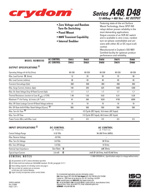
Series A48, D48 12-90Amp • 480 Vac - AC OUTPUT
• Zero Voltage and Random Turn-On Switching • Panel Mount • 800V Transient Capability • Internal Snubber
MOUNTING HOLE/SLOT 0.17 (4.3) DIA.
1.10 (27.9)
.45 (11.4)
FASTON TERMINAL .250 X .032 (2 PLCS.)
.87 REF. (22.2)
Crydom Heat Sinks offer excellent thermal management and are perfectly matched to the load current ratings of Crydom panel mount relays. Request Crydom’s Heat Sink specification sheet for all the details.
Crydom Inc., 2320 Paseo de las Americas, Ste. 201, San Diego, CA 92154
Email: sales@ WEB SITE:
SERIES A48/D48.
UK: +44 (0)1202 606030 • FAX +44 (0)1202 606035 Crydom SSR Ltd., Arena Business Centre,
A4850 D4850
A4875 D4875
A4890 D4890
Operating Voltage (47-63 Hz) [Vrms]
- 1、下载文档前请自行甄别文档内容的完整性,平台不提供额外的编辑、内容补充、找答案等附加服务。
- 2、"仅部分预览"的文档,不可在线预览部分如存在完整性等问题,可反馈申请退款(可完整预览的文档不适用该条件!)。
- 3、如文档侵犯您的权益,请联系客服反馈,我们会尽快为您处理(人工客服工作时间:9:00-18:30)。
2:1 Range 4:1 Range
Safe Operating Area
80 60
40
20 0
60%
-25 0 25 50 75 100
70
Operating Temperature (°C)
Is 2:1 Range Is 4:1 Range
Recommended Footprint Details
Pin Connections
3 1 2
5 10.16 2.54 10.16 2 1 4 3 2.54 2.54
Top View
5.08
Bottom View 4
Pin # 1 2 3 4 5
Single +Vin –Vin +Vout No Pin -Vout
REC10-S_DRW(Z)/H Series
-25°C to +70°C (see Graph) -25°C to +70°C (see Graph) -55°C to +105°C +100°C max. ±0.02%/°C 95% RH
Nickel Plated Copper with Non-Conductive Base, Six-side Shielded Natural convection 32g using MIL-HDBK 217F using MIL-HDBK 217F EN 55022 class A 800 x 103 hours 256 x 103 hours
Designed to meet EN-60950-1 UL-60950-1 Pending
4:1 * add suffix "/CTRL" for optional Remote ON/OFF-Control xx = 9-36Vin = 24 xx = 18-75Vin = 48
Specifications (Core Operating Area)
Dual +Vin –Vin +Vout Com -Vout
5
XX.X ± 0.5 mm XX.XX ± 0.25 mm
1.2ø+0.2/0.1
REC10-Series also available with Remote ON/OFF - Control
For order information please contact your RECOM representative.
元器件交易网
Features
Regulated Converters
● ● ● ● ● ● ● ●
10W 1”x 2” Package (50.1x25.4x10.8mm) 1.6kVDC Isolation Wide Input 2:1 & 4:1 Regulated Output UL94V-0 Package Material Continuous Short Circuit Protection Remote ON/OFF-Control for Single Types Efficiency to 84%
元器件交易网
ECONOLINE
DC/DC-Converter
Specifications (Core Operating Area) cont.
Operating Temperature Range (Natural convection) 2:1 (with derating) 4:1 Storage Temperature Range Case Temperature Temperature Coefficient Relative Humidity Case Material Cooling Method Package Weight EMI (Conducted & Radiated Emission) MTBF (+25°C) Detailed Information see (+70°C) Application Notes chapter "MTBF"
}
Package Style and Pinning (mm) 1” x 2” , Wide Input 2:1 & 4:1
1“ x 2“ PIN Package
50.10 10.80 6.00 20.32 20.32 25.40 3rd angle projection 25.40
1.0 15.24 20.32
Input Voltage Range Input Filter Output Voltage Accuracy Line Voltage Regulation 2:1 & 4:1 π type ±2% max. ±0.5% max.
Derating-Graph( Nhomakorabeambient Temperature)
5.08 7.62
Bottom View 4
5
1.2ø+0.2/0.1
XX.X ± 0.5 mm XX.XX ± 0.25 mm
July-2006
125
REC10-S_DRW(Z)/H/CTRL
3 1 2 6
Recommended Footprint Details
6 10.16 2.54 10.16 2 1 5 4 3 2.54 2.54
Top View
Pin Connections Pin # 1 2 3 4 5 6 Single +Vin –Vin +Vout No Pin -Vout CTRL Dual +Vin –Vin +Vout Com -Vout CTRL
120 100
Output Power (%)
Load Voltage Regulation (10% to 100% full load ) ±1% max. Minimum Load 3.3, 5V, ±3.3, ±5Vout 3% 12,15, 24, ±12, ±15Vout 0% Ripple <0.2% Vout +40mVp-p max. Noise <0.5% Vout +50mVp-p max. Operating Frequency Over Power Protection Over Voltage Protection Short Circuit Protection Efficiency at Full Load IIsolation Voltage Rated Working Voltage Isolation Capacitance Isolation Resistance (tested for 1 second) (long term isolation) 300kHz typ. 120%, automatic recovery Zener diode clamp Current limit, auto-recovery 85% max. 1600VDC min. see Application Notes 1000pF 100 MΩ min. continued on next page 124 July-2006
ECONOLINE
DC/DC-Converter
REC10S_DRW(Z)/ H Series
10 Watt 1” x 2” Single & Dual Output
Selection Guide
Part Number 1” x 2” REC10-xx3.3SRW/H REC10-xx05SRW/H REC10-xx12SRW/H REC10-xx15SRW/H REC10-xx24SRW/H REC10-xx3.3SRWZ/H REC10-xx05SRWZ/H REC10-xx12SRWZ/H REC10-xx15SRWZ/H REC10-xx3.3DRWZ/H REC10-xx05DRWZ/H REC10-xx12DRWZ/H REC10-xx15DRWZ/H 2:1 xx = 9-18Vin = 12 xx = 18-36Vin = 24 xx = 36-75Vin = 48 Input Voltage (VDC) 9-18, 18-36, 36-75 9-18, 18-36, 36-75 9-18, 18-36, 36-75 9-18, 18-36, 36-75 9-18, 18-36, 36-75 9-36, 18-75 9-36, 18-75 9-36, 18-75 9-36, 18-75 9-36, 18-75 9-36, 18-75 9-36, 18-75 9-36, 18-75 Output Voltage (VDC) 3.3 5 12 15 24 3.3 5 12 15 ±3.3 ±5 ±12 ±15 Output Current (mA) 2000 2000 830 670 420 2000 2000 830 670 ±1000 ±1000 ±416 ±333 (%) 74-76 80-81 81-84 82-84 81-84 74 77-80 81-82 80-82 74 77-80 81-82 80-82 Efficiency
