BL-Y502通用型压力控制器说明书
贝利摩双向控制阀B250技术数据表说明书

B250•ApplicationStainless Steel Ball and StemTechnical dataFunctional dataValve Size 2" [50]Fluidchilled or hot water, up to 60% glycol Fluid Temp Range (water)0...250°F [-18...120°C]Body Pressure Rating 400 psi Close-off pressure ∆ps 200 psiFlow characteristic equal percentage Servicing maintenance-free Flow Pattern 2-way Leakage rate0% for A – AB Controllable flow range 75°Cv57 No Characterized Disc TRUECv Flow RatingA-port: as stated in chart B-port: 70% of A – AB CvMaterialsValve body Nickel-plated brass body Spindle stainless steel Spindle seal EPDM (lubricated)SeatPTFECharacterized disc No Disc (full flow)Pipe connection NPT female ends O-ring EPDM (lubricated)Ballstainless steel Suitable actuators Non-Spring ARB(X)SpringAFRB(X)Safety notesWARNING: This product can expose you to lead which is known to the State of California to cause cancer and reproductive harm. For more information go to Product featuresThis valve is typically used in air handling units on heating or cooling coils, and fan coil unit heating or cooling coils. Some other common applications include Unit Ventilators, VAV box re-heat coils and bypass loops. This valve is suitable for use in a hydronic system with variable flow.B250 Flow/Mounting detailsTwo-way valves should be installed with thedisc upstream.DimensionsDimensional drawingsARB, ARXA B C D E F H1H210.0" [254] 4.2" [107] 6.9" [175] 5.5" [140] 1.7" [44] 1.7" [44] 1.2" [30]0.6" [15]ARB N4, ARX N4, NRB N4, NRX N4A B C D E F11.4" [289] 4.2" [107]9.8" [249]7.6" [194] 3.1" [80] 3.1" [80]ARQB, ARQXA B C D E F H1H29.9" [251] 4.2" [107]7.5" [191] 6.1" [155] 2.3" [58] 2.3" [58]0.8" [20]0.6" [15]AFRB, AFRXA B C D E F10.8" [275] 4.2" [107]9.5" [241]8.1" [206] 2.0" [51] 2.0" [51]B250AFRB N4, AFRX N4A B C D E F13.0" [330] 4.2" [107]10.3" [262]9.3" [235] 3.4" [86] 3.4" [86]ARX24-3-T On/Off, Floating Point, Non-Spring Return, 24VTechnical dataElectrical data Nominal voltage AC/DC 24 VNominal voltage frequency50/60 HzPower consumption in operation 2.5 WPower consumption in rest position0.5 WTransformer sizing 5.5 VA (class 2 power source)Electrical Connection Terminal blocksOverload Protection electronic thoughout 0...90° rotationFunctional data Direction of motion motor selectable with switch 0/1Manual override external push buttonAngle of rotation90°Angle of rotation note adjustable with mechanical stopRunning Time (Motor)default 90 s, variable 90 or 150 sRunning time motor variable90 or 150 sNoise level, motor45 dB(A)Position indication Mechanically, pluggableSafety data Degree of protection IEC/EN IP54Degree of protection NEMA/UL NEMA 2Enclosure UL Enclosure Type 2Agency Listing cULus acc. to UL60730-1A/-2-14, CAN/CSAE60730-1:02, CE acc. to 2014/30/EUListed to UL 2043 - suitable for use in airplenums per Section 300.22(C) of the NEC andSection 602 of the IMCQuality Standard ISO 9001Ambient temperature-22...122°F [-30...50°C]Storage temperature-40...176°F [-40...80°C]Ambient humidity Max. 95% RH, non-condensingServicing maintenance-freeAccessoriesElectrical accessories Description TypeBattery backup system, for non-spring return models NSV24 USBattery, 12 V, 1.2 Ah (two required)NSV-BAT Electrical installationINSTALLATION NOTESProvide overload protection and disconnect as required.ARX24-3-TActuators may be connected in parallel. Power consumption and input impedance must be observed.Actuators may also be powered by DC 24 V.Actuators Hot wire must be connected to the control board common. Only connect common toneg. (-) leg of control circuits. Terminal models (-T) have no-feedback.Actuators are provided with a numbered screw terminal strip instead of a cable.Meets cULus requirements without the need of an electrical ground connection.Warning! Live electrical components!During installation, testing, servicing and troubleshooting of this product, it may be necessary to work with live electrical components. Have a qualified licensed electrician or other individual who has been properly trained in handling live electrical components perform these tasks. Failure to follow all electrical safety precautions when exposed to live electrical components could result in death or serious injury.Wiring diagrams On/OffFloating PointFloating Point - Triac Source Floating Point - Triac SinkDimensions。
智能控制器使用手册

智能控制器使用手册一概述智能控制器是框架式空气断路器的核心部件,适用于50~60Hz电网,主要用作配电、馈电或发电保护,使线路和电源设备免受过载、短路、接地/漏电、电流不平衡、过压、欠压、电压不平衡、过频、欠频、逆功率等故障的危害;通过负载监控,需量保护,区域连锁等功能实现电网的合理运行。
同时也用作电网节点的电流、电压、功率、频率、电能、需量、谐波等电网参量的测量;故障、报警、操作、电流历史最大值、开关触头磨损情况等运行维护参数的记录;当电力网络进行通讯组网时,智能控制器可用为电力自动化网络的远程终端实现遥测,遥信,遥控,遥调等,智能控制器支持多种协议以适用不同的组网要求。
二基本功能对于M型无任何可选功能(加*的项目)时其功能配置为基本功能,如表1所示:表1 基本功能配置2.1.3 通讯功能通讯功能为可选项,对于M型没有通讯功能,对于H 型通讯协议可根据需要选择为Modbus,Profibus-DP,Device net.2.1.4增选功能选择增选功能为可选项,M型,H型都可以选择增选功能配置,不同增选功能代号与增选功能内容如表2所示。
表2 增选功能配置表2.1.5 区域连锁及信号单元的选择“区域连锁及信号单元”为可选项,M型、H型都可以选择信号单元的功能配置,当信号单元选择为S2,S3时,控制器具备区域连锁功能。
2.2 技术性能2.2.1 适用环境工作温度:-10℃~+70℃(24h•内平均值不超过+35℃)储存温度:-25℃~+85℃安装地点最湿月的月平均最大相对湿度不超过90%,同时该月的月平均最低温度不超过+25℃,允许由于温度变化产生在产品表面的凝露。
污染等级:3级。
(在和断路器装配在一起的情况下)安装类别:Ⅲ。
(在和断路器装配在一起的情况下)2.2.2工作电源由辅助电源和电源互感器同时供电,保证负载很小和短路情况下控制都可以可靠工作。
控制器的供电方式有下面3种方式:a.电源CT供电额定电流大于等于400A时,一次电流单相不低于0.4In,三相不低于0.2In时控制器正常工作。
MR-502控制器说明书 V2.0
一、控制器外观
MR-502 俯视图:
①
②
④
③
⑤
地址:北京市通州区九棵树西路 78 号瑞都国际中心 1105 室
邮编:101100
电话:010-80816559
传真:010-80816559-810
3 / 16
MR-502 正视图:
北京明瑞之光科技有限公司
⑥⑦⑧ ⑨
⑩
MR-502 后视图:
传真:010-80816559-810
10 / 16
北京明瑞之光科技有限公司
← 控制器型号
← 工作状态为停止播放
再按
键恢复至播放状态。
14、节目片断选择
在 MR-502 控制器处于播放状态下,按键
或数字键可选择控制器内节目片段。如下
图所示:
← 控制器编号
← 所播放的节目片段编号
三、控制器按键设置参数
⑾
⑿
① LCD 显示屏
② 设置菜单
⒀ ③ 确认并保存
⑤ 减键
⑥ AC12V 供电输入端 ⑦ 直流供电输入端
⑨ 同步线输出端 ⑩ DMX512 信号输出端 ⑾ 串行信号输出端
⒀ SD 存储卡插槽
二、输出端口定义
④ 加键 ⑧ 同步线输入端 ⑿ 遥控器红外接收器
时钟 数据 地线
时钟 数据 地线
编址线 数据 B 数据 A 地线
地址:北京市通州区九棵树西路 78 号瑞都国际中心 1105 室
邮编:101100
电话:010-80816559
传真:010-80816559-810
2 / 16
北京明瑞之光科技有限公司
SM16711、SM16716、SM16703P; LPD1882、LPD1886、LPD6803、LPD8806; WS2801、WS281; MY9221、MY9231; DM412; CX808; P9813; TLC5971、TLC5973; BS0815、BS0825、BS0901; GW6201、GW6205、GW6230、GW6236; 15. 支持标准 USITT DMX512/1990 通用协议和扩展 DMX512 协议,如: DMX512、DMX512AP、UCS512、MY7221、WS2821;
交大方菱数控平面切割控制系统F2500_Ver1.0_操作手册

方菱数控切割机控制系统使用手册(Ver 1.0)(型号:F2500)上海交亿数控设备有限公司2010-08使用注意事项阅读手册本说明书适用于上海交亿数控设备有限公司生产的F2500型数控切割控制系统。
使用前请认真阅读该使用说明书和当地安全条例。
注意:本产品的设计不适合现场维护,如有任何维护要求,请返回上海交亿数控设备有限公司售后服务(维修)中心:地址:上海市紫竹科技园紫日路609号电计大楼201室电话:021-******** 34290970 传真:021-********E-mail:support@环境要求z本数控系统适宜工作在环境温度为-10℃至60℃,相对湿度0-95%无凝结。
z工作电压为DC +24V。
z本控制器应当安装在具有保护粉尘的控制台外壳内。
z本系统最好在远离高压高频等高辐射性的场合使用。
维护z手脚远离运动的机器,控制操作或手动可以通过前面板键盘进行。
z操作机器时不能穿宽松的衣服及有线绳之类的服饰,以防被机器缠住。
z该设备应该且只能由受过培训的人操作。
z不是本公司授权的技术人员,严禁自主拆缷机器。
z使用时,切勿溅泼酸性、碱性、腐蚀性等物品到本控制系统上。
高压电z电击能伤人致死。
必须按照装箱件规定步骤及要求进行安装。
z电源接通时,不能接触电线及电缆。
z该设备应该且只能由受过培训的人操作。
目录方菱数控切割机控制系统 (I)使用手册(VER 1.0) (I)阅读手册.............................................................................................................................................. I I 环境要求.............................................................................................................................................. I I 维护...................................................................................................................................................... I I 高压电.................................................................................................................................................. I I第一章概述 (1)1.1系统简介 (1)1.2系统特点 (1)1.3技术指标 (2)1.4系统接口 (2)1.5硬件配置 (2)第二章系统开机 (4)2.1系统操作面板说明 (4)2.2系统启运及主界面说明 (4)2.3主界面功能索引 (7)第三章切割功能 (8)3.1切割操作索引 (10)3.2调速 (11)3.2.1 正常调速 (11)3.2.2 快速调速 (11)3.3前进 (11)3.4后退 (11)3.5边缘切割/偏移切割/返回 (11)3.6图形功能 (12)3.7氧燃气预热时间调整 (14)3.7选穿孔点 (15)3.7动态放大 (16)第四章部件选项 (18)4.1XY镜像 (18)4.2角度校正 (19)3.8镜像 ............................................................................................................. 错误!未定义书签。
JYB压力液位变送器使用说明书V2.1

·产品防护型外壳设计。
·本产品由电路板、传感器等重要部件组成。
P 类防爆防护型压力液位变送器螺纹安装尺寸
二.用 途:
适用于工业本安防爆现场过程控制压力的测量。
三.主要技术参数: 1、输出形式:4mA ~20mA 2、供电电源:DC 24V(12V~32V) 3、量程范围:□ 量程(0~100)MPa 内 0.5 级 □ 量程(0~5)MPa 内 0.2 级 (传感器最小量程 5kPa) 4、准确度等级:□0.5 级 □0.2 级 5、介质温度:-20℃~60℃ 6、环境温度:-20℃~60℃ 7、响应时间:≤50ms 8、负载能力(DC 24V):电流型≤500Ω 9、可重复性:±0.1%F·S 10、年长期稳定性:±0.1%F·S 11、非线性:±0.2%F·S 12、热力零点每度温漂:±0.02%F·S 13、过载压力:2 倍量程 14、电气连接:标准霍斯曼接头 15、测量介质:各种无腐蚀性气体或液体 16、防爆标志:ExiaIICT6 Ga 17、本安参数 Ui= 28VDC Ii=93mA Pi=0.65W Ci=0.03μF Li=0.1mH 18、防爆关联设备:安全栅 19、防护等级:IP65 20、产品重量:约 1150g 工作条件: 避免安装在机械震动和较强电磁干扰的环境下 外形及尺寸:
确认问题后需要把变送器寄回本公司维修时请附带以下
信息:
·现场环境描述;
·故障现象;
·测量介质以及其物理化学性质描述;
当变送器需要维修或校准时,请在寄回前务必把残余的介
质清理干净,特别是对人身健康有害的物质,如腐蚀性,
有毒的,致癌的或具有辐射性的物质。
常见故障分析与排除
贝加莱50点壁厚控制器说明书3.30

PP41型壁厚控制器使用说明书贝加莱工业自动化(上海)有限公司目录系统特性简介 (3)1系统特性介绍 (3)2控制系统各部件介绍 (4)2.1控制操作面板 (4)2.1.1 面板 42.1.2 接口 52.1.3 性能 62.1.4 安装 62.2功能按键及指示灯 (7)2.3控制器及接线 (9)2.3.1AI351 (9)2.3.2 Am351 (10)2.3.3 PP41自带输入 (10)2.3.4 PP41自带输出 (11)3画面操作说明 (12)3.1登陆画面 (12)3.2连续式型胚曲线设定画面 (12)3.2.1 操作按钮 (12)3.2.2 输入参数 (13)3.2.3 输出参数 (14)3.2.4 插入与删除设定数值点 (14)3.2.5 微调设定数值点间的曲线单元 (15)3.3储料式型胚曲线设定画面 (17)3.3.1 操作按钮 (17)3.3.2 输入参数 (18)3.3.3 输出参数 (19)3.4曲线跟踪画面 (19)3.5标记画面 (20)3.6存储画面 (20)3.7文件改名画面 (21)3.8参数存储画面 (21)3.9文件调出画面 (22)3.10监控画面 (22)3.11数据1(曲线点)画面 (22)3.12数据2画面 (23)3.13初始设定画面 (23)3.13.1 输入参数 (23)3.13.2 模式转换 (24)3.14型芯设定画面 (24)3.14.1 输入参数 (24)3.14.2 输出参数 (25)3.14.3 手动调校 (25)3.14.4 自动调校 (25)3.14.5 调校提示: (25)3.15储料设定画面 (26)3.15.1 输出参数 (26)3.15.2 手动调校 (26)3.16增益设定画面 (26)3.16.1 按钮 273.16.2 输入参数 (27)3.16.3 输出参数 (27)3.17时间设定画面 (27)3.17.1 输入参数 (27)3.17.2 输出参数 (27)3.18中英文切换画面 (28)4机器操作说明 (29)4.1开机步骤 (29)4.2系统参数设定 (29)4.2.1 初始设定 (29)4.2.2 型芯设定 (29)4.2.3 储料设定 (29)5故障处理 (30)5.1故障对应 (30)5.2干扰处理 (30)6电源 (30)7附件 (30)系统特性简介1 系统特性介绍这是一款50点型坯壁厚控制器,用来控制中空成型机型坯的壁厚。
WJ(M-PRO)系列控制器使用说明书
西门子通用控制器RLU2-
电缆长度 继电器触点
开关电压
交流电 在 250 V 在 19 V
接通电流 在 AC 250 V 的接触寿命
在 0.1 A res. 在 0.5 A res.
在 4 A res.
品质因数 (cos φ = 0.6) 绝缘强度
继电器触点和系统电子设备之间 (加强绝缘) 邻近继电器触点之间(操作绝缘) Q1⇔Q2; Q3⇔Q4; Q5⇔Q6 继电器组之间 (加强绝缘) (Q1, Q2) ⇔ (Q3, Q4) ⇔ (Q5, Q6)
型号
通用
参数
输入
RLU210
3
RLU222
4
RLU232
5
RLU236
5
名称 操作维护工具 时间控制器
数字输入
1 1 2 2
调节输出
开关输出 控制回路
1
0
2
2
3
2
3
6
型号参数 OCI700.1 SEH62.1
1 1 2 2
数据表 N5655 N5243
2/26
Siemens Building Technologies HVAC Products
Siemens Building Technologies HVAC Products
Universal controllers RLU2...
3/26
CE1N3101en 07.01.2004
工程注释
放置和安装注释
Low-voltage side Mains-voltage side
3101Z07en
较大的塑料件附有材料标记,符合 ISO / DIS 11 469 标准,以利于环境兼容处理。
压力控制器使用说明书
压力控制器使用说明书
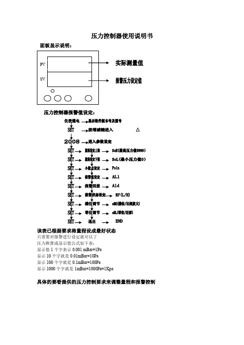
面板显示说明:
该表已根据要求将量程设成最好状态
只需要对报警进行设定就可以了
压力换算成显示值公式如下表:
显示值1个字表示0.001 mBar=1Pa
显示10个字就是0.01mBar=10Pa
显示100个字就是0.1mBar=100Pa
显示1000个字就是1mBar=1000Pa=1Kpa
具体的要看提供的压力控制要求来调整量程和报警控制
压力开关原理及工作电路
气体的压力经过压力传感器转换成电流信号通过压力控制器的主CPU处理后显示在控制控制器的PV屏上。
控制的压力值显示在SV屏上,控制压力可以根据实际环境的要求设定,实现全智能控制模式。
继电器带有常开/常闭触点,可以根据现场的要求进行状态设定,以满足现场的要求。
离合器使用说明书(压力控制器)

4、三号压力控制器(工作压力检测)压力调到 6.5kg/cm2(0.65MPa)。 5、减压阀压力调到 7kg/cm2。(0.7MPa) 6、若整个系统连锁正常,有关设备均已处于"起动准备”状态,磨机启动前的准备工作
即告完成。 九、磨机的启动
启动磨机之前应作如下常规检查 1、确认减压阀、安全阀的调定压力符合规定,压力表的读数不低于 7 Kgf/cm2(0.7Mpa); 2、检查整个系统是否漏气,发现问题,及时处理。 ㈠ 离合器的试启动 1、磨机主电机不开,调减压阀压力到 7~7.3kg/cm2,向离合器冲气,离合器冲气迅速无 堵塞。 2、离合器调好后放气迅速。 3、冲放数次。 ㈡ 磨机的启动 1、确认指示灯指示离合器内无大于 0.4kgf/cm2(0.04MPa)的压力后,启动磨机主电动机。 2、气动离合器电控箱上的绿灯亮时,电动机即已达到其同步转速。 3、电动机达到同步转速后,向离合器充气。磨机启动,此时应测定磨机由静止状态达到 额定转速所需的时间,磨机达到额定速度的时间不应超过 7 秒。 4、放出离合器里的压缩空气,使离合器脱开。 5、调整单向节流阀,使磨机由静止至达到额定转速的时间(加速全过程)在 4~7 秒之间 完成,拧紧背帽,锁紧调整螺钉。调整单向节流阀一定要针对磨机负荷条件进行。磨机满负荷 运行时单向节流阀全开。 6、必须避免连续三次以上的启动,防止烧坏离合器。两次启动的间隔时间不得少于 15 分钟。 十、离合器的维护 1、空压机 2~4 周定期排水。 2、进气‘分水滤汽器’每班定期排水排脏,出气‘分水滤汽器’每班定期排水排脏。冲 气不畅更换滤芯。 3、空压机定期更换润滑油。 十一、操作 首先要确认电动机控制柜上的指示灯指示离合器内无空气压力后,方能起动主电动机,
工作至关重要,要按规定的管子尺寸接入和接出气动控制系统。
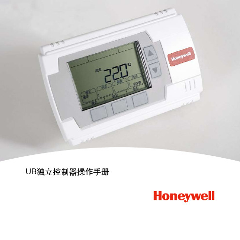
UB系列控制器操作手册
(3) 按功能键2(切换)选择设定的小时(0~23)或分钟(0~59),被选择的设定项闪烁。 (4) 用上下键选择时间值后,选择确认,返回设置界面(图2-1-1)。 2.1.1.2 设置系统日期
page -6-
(1) 在开机初始界面下,按功能键2(设定)3秒进入设置界面,如图2-1-1。 (2) 用上下键选择日期设置项,按功能键2(设定)进入日期设定界面,如图2-1-3。
图2-1-3 日期设定界面
(3)用上下键选择当前日期,被选择的日期闪烁。 (4)选定后,选择确认,返回设置界面(图2-1-1)。 2.1.1.3 时钟异常
如果时钟出现异常,则控制器在开启时,会自动进入时间设定界面,如图2-1-2。 2.1.2 日节能程序时间设定
控制器提供一周7天、一天4个开或关时段的定时设置: 时段1:为系统开启设定时间段; 时段2:为系统关闭设定时间段; 时段3:为系统开启设定时间段; 时段4:为系统关闭设定时间段。 定时功能可设置为启用或和禁止。定时功能启用时,根据时段判断是否启动;定时功能设置为禁止时,系统启动。 2.1.2.1 修改/创建日时间程序
page -10-
⑴ 相对湿度参数设定范围为 20%RH ~ 80%RH ⑵ 在参数设定界面(图2-2-1)按功能键2(切换)选择相对湿度设定。 ⑶ 按上下键改变湿度参数值,步进值为1.0%RH。按住上下键3秒后数值加速改变。当达到湿度范围上限或下限后,相对湿度值不再变化。 ⑷ 确定相对湿度参数后,按图2-2-1中功能键3(确认)或等待15秒后保存并退出参数设定。 2.2.2.4 压力参数设定 (仅型号UB4334SCH/EN适用) ⑴ 压力参数设定范围为 100Pa ~ 2500Pa。 ⑵在参数设定界面(图2-2-1)按功能键2(切换)选择压力设定。 ⑶ 按上下键改变压力参数值,步进值为25Pa。按住上下键3秒后数值加速改变。当达到压力范围上限或下限后,压力参数值不再变化。 ⑷ 确定压力参数值后,按图2-2-1中功能键3(确认)或等待15秒后保存并退出设定状态。 2.2.3设备运行模式的设定
LIA-202 压力释放阀使用及维护手册说明书

©Copyright Task Force Tips LLC 2004-2019LIA-202 November 12, 2019 Rev05INSTRUCTIONS FOR SAFE OPERATION AND MAINTENANCEUnderstand manual before use. Operation of this device without understanding the manual and receiving proper training is a misuse of this equipment. Obtain safety information at / serialnumber.This instruction manual is intended to familiarize fi re fi ghters and maintenance personnel with the operation, servicing, and safety procedures associated with this product.This manual should be kept available to all operating and maintenance personnel.Flange Mounted PRVFlange Mounted PRV with Galvanic IsolatorFlange mounted PRVs are available with a variety of outlets. Consult the catalog, factory, or to fi nd the con fi guration for your application.TASK FORCE TIPS LLCMADE IN USA • 3701 Innovation Way, Valparaiso, IN 46383-9327 USA800-348-2686 • 219-462-6161 • Fax 219-464-7155©Copyright Task Force Tips LLC 2004-2019LIA-202 November 12, 2019 Rev052©Copyright Task Force Tips LLC 2004-2019LIA-202 November 12, 2019 Rev0531.0 MEANING OF SAFETY SIGNAL WORDSA safety related message is identi fi ed by a safety alert symbol and a signal word to indicate the level of risk involved with a particular hazard. Per ANSI standard Z535.6-2011, the de fi nitions of the four signal words are as follows:DANGER indicates a hazardous situation which, if not avoided, will result in death or seriousinjury.WARNING indicates a hazardous situation which, if not avoided, could result in death or serious injury.CAUTION indicates a potentially hazardous situation which, if not avoided, could result in minoror moderate injury.NOTICE is used to address practices not related to physical injury.TABLE OF CONTENTS1.0 MEANING OF SIGNAL WORDS2.0 SAFETY3.0 GENERAL INFORMATION 3.1 DIMENSIONS 3.2 INSTALLATION 3.3 USE WITH SALT WATER4.0 RELIEF VALVE PRESSURE SETTING5.0 RELIEF VALVE FLOW VS. PRESSURE CURVE6.0 WARRANTY7.0 MAINTENANCE AND INSPECTION 8.0 TESTING©Copyright Task Force Tips LLC 2004-2019LIA-202 November 12, 2019 Rev0542.0 SAFETYThe equipment may be damaged if frozen while containing signi fi cant amounts of water. Such damage may be di ffi cult to detect visually. Subsequent pressurization can lead to injury or death. Any time the equipment is subject to possible damage due to freezing, it must be tested and approved for use by quali fi ed personnel before being considered safe for use.3.0 GENERAL INFORMATIONThe Pressure Relief Valve may be set to any pressure between 90 and 300 psi. Its function is to protect the pump and the supplyhose from excess pressure. The relief valve may be mounted with its opening facing the front, back, right, or left. A section of tubing or pipe may be mounted on the round spout to route the water in any direction.Primary MaterialsHard anodized and powder coated aluminum, POM, Nitrile Operating Temperature Range of Fluid 33 to 120°F (1 to 50°C)Storage Temperature Range-40 to 150°F (-40 to 65°C)3.1 DIMENSIONSAINLET CONNECTIONINLET HEIGHTSTANDARD/DARLEY FLANGE0.00 [0]STANDARD/DARELY WITH GALVANIC ISOLATOR 0.50 [13]2.5” NPTM WITH GALVANIC ISOLATOR 2.75 [70]2.5” NPTF WITH GALVANIC ISOLATOR 2.00 [51]3.0” NPTM WITH GALVANIC ISOLATOR 2.75 [70]3.0” NPTF WITH GALVANIC ISOLATOR2.38 [60]Dimensions in inches (millimeters)BOUTLET CONNECTION OUTLET LENGTH NO EXIT THREADS 4.34 [110]2.0” NPTM 4.26 [108]2.5” NPTM 5.53 [141]2.5” VICTAULIC 5.07 [129]2.5” NHM 5.57 [141]2.5” NPTF 5.57 [141]Dimensions in inches (millimeters)Visit for more detailed drawings, speci fi cations, feature lists, and certi fi cations speci fi c to your model number.PRV con fi gurations for use on fi re apparatus plumbing, or connected to a metal other than aluminuminclude an integrated galvanic isolator. These models are 1/2” taller that those mounted to TFT appliances.©Copyright Task Force Tips LLC 2004-2019LIA-202 November 12, 2019 Rev0553.2 INSTALLATIONTo install the fl ange mounted Pressure Relief Valve:Required parts:• (4) 7/16” bolts of appropriate length for your application (Models with a galvanic isolator require 1/2” longer bolts)• Thread locking compound such as Loctite 242• Torque wrench • O-ring (provided)1. Install the O-ring in the groove on either the Pressure Relief Valve casting or the integrated galvanic isolator.2. Place the PRV in the desired orientation. Be sure that the PRV is aligned with the opening Tightening the bolts with the PRVtilted to one side may damage the galvanic isolator.3. Apply a drop of thread locking compound on the threads of the bolts to prevent them from coming loose.4. Loosely install the bolts through the fl ange of the PRV.5. Uniformly tighten the bolts 3 time each in an alternating pattern to a fi nal torque of 140in/lb.1234Tighten bolts in an alternating pattern as shown at left.Complete the pattern for each bolt fi rst to 40 in/lb,then to 80 in/lb, and fi nally to 140 in/lb.3.3 USE WITH SALT WATERUse with salt water is permissible provided the equipment is thoroughly cleaned with fresh water after each use. The service life ofthe equipment may be shortened due to the e ff ects of corrosion, and is not covered under warranty.4.0 RELIEF VALVE PRESSURE SETTINGTo set the relief valve pressure, turn the adjusting screw on the relief valve housing until the surface of the screw is even with the step marked with the desired pressure.Do not cap or plug discharge opening.To turn o ff the Pressure Relief Valve, align the adjusting screw with the OFF position. Placing the Pressure Relief Valve in the OFF position prevents the valve from venting water. Do not use the OFF position for normal operations. System damage may occur if the Pressure Relief Valve is in the OFF position and the system exceeds its operating limits.The Pressure Relief Valve meets the requirements of NFPA 1901.90 PSI200 PSIOFFUse a 1/4” (7mm) hex key or 9/16” (14mm) socket/wrench when setting the height of the adjusting screw to the desired relief pressure.The Pressure Relief Valve is disabled in the OFF position and off ers no system protection against over-pressurization. Avoid water hammer or other pressure spikes during pump tests. Ensure PRV is returned to its normal pressure setting following pump testing.Severe water hammer may cause pressure spikes exceeding the Pressure Relief Valve’s capacity. Large spikes can result in injury from ruptured hose or system components. Review fl ow capacity of the Pressure Relief Valve. Add more PRVs if additional fl ow capacity is needed. Always operate valves slowly to avoid the risk of water hammer.5.0 RELIEF VALVE FLOW vs. PRESSURE CURVE6©Copyright Task Force Tips LLC 2004-2019 LIA-202 November 12, 2019 Rev056.0 WARRANTYTask Force Tips LLC, 3701 Innovation Way, Valparaiso, IN 46383-9327 USA (“TFT”) warrants to the original purchaser of its Pressure Relief Valve (“equipment”), and to anyone to whom it is transferred, that the equipment shall be free from defects in material and workmanship during the fi ve (5) year period from the date of purchase.TFT’s obligation under this warranty is specifi cally limited to replacing or repairing the equipment (or its parts) which are shown by TFT’s examination to be in a defective condition attributable to TFT. To qualify for this limited warranty, the claimant must return the equipment to TFT, at 3701 Innovation Way, Valparaiso, IN 46383-9327 USA, within a reasonable time after discovery of the defect. TFT will examine the equipment. If TFT determines that there is a defect attributable to it, TFT will correct the problem within a reasonable time. If the equipment is covered by this limited warranty, TFT will assume the expenses of repair.If any defect attributable to TFT under this limited warranty cannot be reasonably cured by repair or replacement, TFT may elect to refund the purchase price of the equipment, less reasonable depreciation, in complete discharge of its obligations under this limited warranty. If TFT makes this election, claimant shall return the equipment to TFT free and clear of any liens and encumbrances.This is a limited warranty. The original purchaser of the equipment, any person to whom it is transferred, and any person who is an intended or unintended benefi ciary of the equipment, shall not be entitled to recover from TFT any consequential or incidental damages for injury to person and/or property resulting from any defective equipment manufactured or assembled by TFT. It is agreed and understood that the price stated for the equipment is in part consideration for limiting TFT’s liability. Some states do not allow the exclusion or limitation of incidental or consequential damages, so the above may not apply to you.TFT shall have no obligation under this limited warranty if the equipment is, or has been, misused or neglected (including failure to provide reasonable maintenance) or if there have been accidents to the equipment or if it has been repaired or altered by someone else.THIS IS A LIMITED EXPRESS WARRANTY ONLY. TFT EXPRESSLY DISCLAIMS WITH RESPECT TO THE EQUIPMENT ALL IMPLIED WARRANTIES OF MERCHANTABILITY AND ALL IMPLIED WARRANTIES OF FITNESS FOR A PARTICULAR PURPOSE. THERE IS NO WARRANTY OF ANY NATURE MADE BY TFT BEYOND THAT STATED IN THIS DOCUMENT.This limited warranty gives you specifi c legal rights, and you may also have other rights which vary from state to state.7©Copyright Task Force Tips LLC 2004-2019 LIA-202 November 12, 2019 Rev057.0 MAINTENANCE AND INSPECTIONThe Pressure Relief Valve requires no routine maintenance but should be tested regularly. Since the Pressure Relief Valve may not need to open in normal use, it is important that it be inspected at least quarterly for proper function per NFPA 1962 or annually per NFPA 1911, depending on the application. In particular, assure that:• There is no damage such as cracks or dents• There is no corrosion• Setting indications are readable• The waterway is clear of obstructions• The valve opens at the set pressureIf any problems are found, the Pressure Relief Valve should be removed from service until the problem is corrected. Any repaired Pressure Relief Valve must be tested before being placed in service.8.0 TESTINGIt is important that your Pressure Relief Valve (PRV) is functioning properly at all times while in service. A properly functioning PRV prevents dangerous situations and reduces possible injury. In order to ensure the PRV is functioning properly, it should be tested regularly. NFPA standards set forth the minimum requirements and procedures for inspecting and testing these valves. It is strongly recommended that you read and follow the procedures.For PRVs mounted to piping of in-service emergency vehicles:NFPA 1911: Inspection, Maintenance, Testing, and Retirement of In-Service Emergency VehiclesFor PRVs mounted to a fi re hose appliance:NFPA 1962: Standard for the Care, Use, Inspection, Service Testing, and Replacement of Fire Hose, Couplings, Nozzles, and Fire Hose AppliancesAny valves taken out of service due to failure should be returned to the factory for repair or replacement. If you have any questions regarding the testing or maintenance of your Pressure Relief Valve, please call Task Force Tips at 800-348-2686.TASK FORCE TIPS LLC MADE IN USA • 3701 Innovation Way, Valparaiso, IN 46383-9327 USA 800-348-2686 • 219-462-6161 • Fax 219-464-7155©Copyright Task Force Tips LLC 2004-2019 LIA-202 November 12, 2019 Rev05。
Belimo EP050+ARX-E N4HH 压力独立门弯控制器说明书
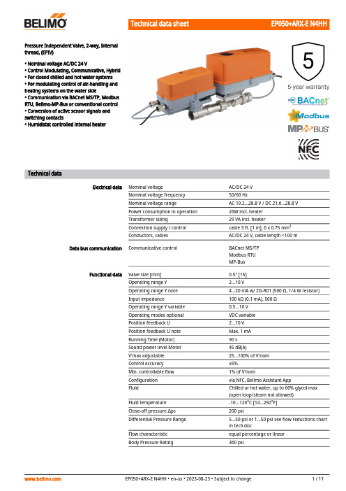
Pressure Independent Valve, 2-way, Internalthread, (EPIV)• Nominal voltage AC/DC 24 V• Control Modulating, Communicative, Hybrid• For closed chilled and hot water systems• For modulating control of air-handling andheating systems on the water side• Communication via BACnet MS/TP, ModbusRTU, Belimo-MP-Bus or conventional control• Conversion of active sensor signals andswitching contacts• Humidistat controlled internal heaterTechnical dataElectrical data Nominal voltage AC/DC 24 VNominal voltage frequency50/60 HzNominal voltage range AC 19.2...28.8 V / DC 21.6...28.8 VPower consumption in operation26W incl. heaterTransformer sizing29 VA incl. heaterConnection supply / control cable 3 ft. [1 m], 6 x 0.75 mm²Conductors, cables AC/DC 24 V, cable length <100 m Data bus communication Communicative control BACnet MS/TPModbus RTUMP-BusFunctional data Valve size [mm]0.5" [15]Operating range Y 2...10 VOperating range Y note 4...20 mA w/ ZG-R01 (500 Ω, 1/4 W resistor)Input impedance100 kΩ (0.1 mA), 500 ΩOperating range Y variable0.5...10 VOperating modes optional VDC variablePosition feedback U 2...10 VPosition feedback U note Max. 1 mARunning Time (Motor)90 sSound power level Motor45 dB(A)V'max adjustable25...100% of V'nomControl accuracy±5%Min. controllable flow1% of V'nomConfiguration via NFC, Belimo Assistant AppFluid Chilled or hot water, up to 60% glycol max(open loop/steam not allowed)Fluid temperature-10...120°C [14...250°F]Close-off pressure ∆ps200 psiDifferential Pressure Range 5...50 psi or 1...50 psi see flow reductions chartin tech docFlow characteristic equal percentage or linearBody Pressure Rating360 psiTechnical dataFunctional data Leakage rate0% leakageGPM 6.6Pipe connection Internal threadNPT (female)Installation orientation upright to horizontal (in relation to the stem)Servicing maintenance-freeManual override external push buttonThermostat / Humidistat Type of contact Normally closed contactHeating output21 WSwitch-on current Max. 2.5 ASettings65% RH fixedHeater Aluminium profile, anodizedSensor element ThermobimetalMeasuring data Measured values FlowFlow measurement Measuring principle Ultrasonic volumetric flow measurementMeasuring accuracy flow±2%Min. flow measurement0.5% of V'nomMeasurement Repeatability±0.5% (Flow)Sensor Technology Ultrasonic with glycol and temperaturecompensationSafety data Degree of protection IEC/EN IP66Degree of protection NEMA/UL NEMA 4Enclosure UL Enclosure Type 4Pressure equipment directive CE according to 2014/68/EUQuality Standard ISO 9001UL 2043 Compliant Suitable for use in air plenums per Section300.22(C) of the NEC and Section 602 of theIMCRated impulse voltage supply / control0.8 kVAmbient humidity Max. 100% RHAmbient temperature-22...122°F [-30...50°C]Storage temperature-40...176°F [-40...80°C]Materials Valve body Nickel-plated brass bodyFlow measuring pipe brass body nickel-platedValve plug Stainless steelStem stainless steelStem seal EPDM (lubricated)Seat PTFECharacterized disc TEFZEL®O-ring EPDMBall stainless steel••••Safety notesThis device has been designed for use in stationary heating, ventilation and air-conditioning systems and must not be used outside the specified field of application, especially in aircraft or in any other airborne means of transport.Outdoor application: only possible in case that no (sea) water, snow, ice, insolation or aggressive gases interfere directly with the actuator and that is ensured that the ambient conditions remain at any time within the thresholds according to the data sheet.Only authorized specialists may carry out installation. All applicable legal or institutional installation regulations must be complied during installation.The device contains electrical and electronic components and must not be disposed of as household refuse. All locally valid regulations and requirements must be observed.ApplicationMode of operationFlow measurement Product featuresWater-side control of heating and cooling systems for AHUs and water coils.The HVAC performance device is comprised of three components: characterized control valve (CCV), measuring pipe with flow sensor and the actuator itself. The adjusted maximum flow (V'max) is assigned to the maximum control signal (typically 100%). The HVAC performance device can be controlled via communicative signals. The fluid is detected by the sensor in the measuring pipe and is applied as the flow value. The measured value is balanced with the setpoint. The actuator corrects the deviation by changing the valve position. The angle of rotation α varies according to the differential pressure through the control element (see flow curves).All flow tolerances are at 68°F [20°C] & water.Flow rate curvesControl characteristics The fluid velocity is measured in the measuring component (sensor electronics) and converted to a flow rate signal.The control signal Y corresponds to the power Q via the exchanger, the volumetric flow isregulated in the EPIV. The control signal Y is converted into a linear characteristic curve andprovided with the V'max value as the new reference variable w. The momentary controldeviation forms the control signal Y1 for the actuator.The specially configured control parameters in connection with the precise flow rate sensorensure a stable quality of control. They are however not suitable for rapid control processes, i.e.for domestic water control. U5 displays the measured flow as voltage (factory setting).Parametrizing V'max with ZTH:U5 refers to the respective V'nom, i.e. if V'max is e.g. 50% of V'nom, then Y = 10 V, U5 = 5 V.Parametrizing V'max with PC-Tool:In the PC-Tool, the maximum flow rate to which U5 refers can be set individually. If V'max ischanged (e.g. to 70% V'nom), the U5 flow range is also automatically changed to the same value(e.g. 70% V'nom: U5 = 10 V). This adjustment can be reversed by entering a value manually (U5flow range = 100%: U5 refers to V'nom).As an alternative, U5 can be used for displaying the valve opening angle.Creep flow suppressionConverter for sensorsControl signal inversionHydronic balancing Combination analogue - communicative(hybrid mode)Manual override Flow controlV'nom is the maximum possible flow.V'max is the maximum flow rate which has been set with the highest control signal DDC. V'maxcan be set between 25% and 100% of V'nom.Given the very low flow speed in the opening point, this can no longer be measured by the sensor within the required tolerance. This range is overridden electronically.Opening valveThe valve remains closed until the flow required by the control signal DDC corresponds to 1% of V'nom. The control along the flow characteristic is active after this value has been exceeded. Closing valveThe control along the flow characteristic is active up to the required flow rate of 1% of V'nom. Once the level falls below this value, the flow rate is maintained at 1% of V'nom. If the level falls below the flow rate of 0.5% of V'nom required by the control signal DDC, then the valve willclose.Connection option for a sensor (active or with switching contact). In this way, the analog sensor signal can be easily digitized and transferred to the bus systems BACnet, Modbus or MP-Bus.This can be inverted in cases of control with an analog control signal. The inversion causes the reversal of the standard behavior, i.e. at a control signal of 0%, is equal to V'max, and the valve is closed at a control signal of 100%.With the Belimo tools, the maximum flow rate (equivalent to 100% requirement) can be adjusted on-site, simply and reliably, in a few steps. If the device is integrated in the management system, then the balancing can be handled directly by the management system. With conventional control by means of an analog control signal DDC, BACnet, Modbus, or MP-Bus can be used for the communicative position feedback.Manual control with push-button possible - temporary. The gear train is disengaged and the actuator decoupled for as long as the button is pressed.Product featuresAccessoriesTools Description TypeConverter Bluetooth / NFC ZIP-BT-NFC Electrical installationSupply from isolating transformer.The wiring of the line for BACnet MS/TP / Modbus RTU is to be carried out in accordance withapplicable RS485 regulations.Modbus / BACnet: Supply and communication are not galvanically isolated. Connect earth signalof the devices with one another.Modbus RTU / BACnet MS/TP with analogue setpoint (hybrid mode)BACnet MS/TP / Modbus RTUCable colors:1= black2 = red3 = white5 = orange6 = pink7 = greyBACnet / Modbus signalassignment:C1 = D– = AC2 = D+ = BConnection with active sensor, e.g. 0...10 V @ 0...50°CPossible voltage range:0...32 V (resolution 30 mV)Connection with switching contact, e.g. Δp monitorRequirements for switching contact:The switching contact must be able to accurately switch a current of 16 mA @ 24 V.Operation on the MP-BusConnection with active sensorConnection with switching contact, e.g. Δp monitorSwitching contact requirements: The switching contact must be able to switch a current of 16 mA at 24 V accurately.Connection with active sensor, e.g. 0...10 V @ 0...50°CPossible input voltage range: 0...10 VResolution 30 mVElectrical installationFunctionsFunctions with specific parameters (parametrisation necessary) M-Bus with converter in parallelmode with PoE with BACnet IP /Modbus TCPExamples of external wiring with actuator types ..24GX..A = ActuatorH [% RH] = HumidistatH = HeatingOperating controls and indicators1LED display green On:Device starting upOff:No power supply or wiring error Flashing:In operation (Voltage ok)2Flow direction 3NFC interface4Manual override button Press button:Gear train disengages, motor stops, manual override possible Release button:Gear train engages, standard mode. Device performs synchronisation.2Cover, POP button 3POP button4Scale for manual adjustment 5Manual override button Press button:Gear train disengages, motor stops, manual override possible Release button:Gear train engages, standard mode6Push-button (LED yellow)Press button:Acknowledgment of addressingPush-button (LED Green)Press button:Triggers angle of rotation adaptation, followed by standard modeSetting fail-safe positionSetting emergency setting position (POP)Operating controls and indicatorsPermissible installation orientationInstallation position in return Water quality requirementsServicing Flow directionInstallation notesThe ball valve can be installed upright to horizontal. The ball valve may not be installed in ahanging position, i.e. with the stem pointing downwards.Installation in the return is recommended.The water quality requirements specified in VDI 2035 must be adhered to.Belimo valves are regulating devices. For the valves to function correctly in the long term, they must be kept free from particle debris (e.g. welding beads during installation work). The installation of a suitable strainer is recommended.Ball valves, rotary actuators and sensors are maintenance-free.Before any service work on the control element is carried out, it is essential to isolate the rotary actuator from the power supply (by unplugging the electrical cable if necessary). Any pumps in the part of the piping system concerned must also be switched off and the appropriate slide valves closed (allow all components to cool down first if necessary and always reduce the system pressure to ambient pressure level).The system must not be returned to service until the ball valve and the rotary actuator have been correctly reassembled in accordance with the instructions and the pipeline has been refilled by professionally trained personnel.The direction of flow, specified by an arrow on the housing, is to be complied with, since otherwise the flow rate will be measured incorrectly. EP050+ARX-E N4HH • en-us • 2023-08-23 • Subject to change 11 / 11Cleaning of pipes Prevention of stressesInlet sectionSplit installationBefore installing the valve, the circuit must be thoroughly rinsed to remove impurities. The valve must not be subjected to excessive stress caused by pipes or fittings.In order to achieve the specified measuring accuracy, a flow-calming section or inflow section in the direction of the flow is to be provided upstream from the flow sensor. Its dimensions shouldbe at least 5x DN.The valve-actuator combination may be mounted separately from the flow sensor. The direction of flow of both components must be observed.Installation notesBehaviour in case of sensor failureGeneral notesIn case of a flow sensor error, the EPIV will switch from flow control to position control.Once the error disappears, the EPIV will switch back to the normal control setting.DimensionsDimensional drawingsTypeWeight EP050+ARX-E N4HH[]ABC D E F 26.6" [675]12.0" [305]6.3" [159]9.5" [241] 3.4" [86]3.4" [86]。
压力开关说明书共7页word资料
DG型气体压力开关使用说明书●请阅读和保持一个安全的地方解释符号●, 1, 2, 3 ... = 功能➔= 用法说明所有工作必须在阅读操作说明后才能进行!警告!不正确的安装、调整、修改、操作或维护可能导致伤害或物质损失。
使用前先阅读说明书。
这个单位必须安装依照本条例的实施。
标准声明We, the manufacturer, hereby declare that the products DG.., marked with product ID No. CE 0085AP0467, comply with the essential requirements of the following Directives:–90/396/EEC in conjunction with EN 1854,–73/23/EEC in conjunction with the relevant standards.The relevant products correspond to the type tested by the notified body 0085. Comprehensive quality assurance is guaranteed by a certifi ed Quality System pursuant to DIN EN ISO 9001 according to annex II, para-graph 3 of Directive 90/396/EEC.Elster Kromschröder GmbH, Osnabrück测试➔电源电压、环境温度和外壳——看类型的标签。
➔最大介质温度:-15 + 80°C。
在系统暴露于更高的热应力、热设备上时压力开关必须安装在上游。
DG..B型➔正压时1号位置为进气DG..U型, DG..H型, DG..N型➔正压时1号或者2号位置为进气,气体为空气、天然气或者烟气(其他位置密封),通风时气体从3号或者4号位置离开。
电液式压力试验机 (抗折抗压系列)使用说明书

电液式压力试验机(抗折抗压系列)使用说明书前言衷心感谢您选择了本公司的产品,本公司不仅给您提供质量优异的产品,而且将为您提供优质可靠的售后服务!无锡新路达仪器设备有限公司成立于1995年,坐落在景色秀丽的太湖之滨的滨湖经济技术开发区。
本公司为江苏省计量合格确认单位、无锡市质量信得过单位。
专业研制、生产电液伺服万能试验机(微机控制)、电液式万能试验机(微机屏显)、微机控制恒加载压力试验机、微机控制恒加载抗折抗压试验机、电液式万能试验机、电液式压力试验机等。
本说明书适用于本公司电液式压力试验机系列。
特别提示:有时为了提高设备的性能,我们会对机械部分做一些改动,这可能会导致本说明书与设备在某些细节上不一致,不同之处不再另行通知,敬请谅解。
在编写本说明书时,我们难免有错误和疏漏之处,请多加包涵并热情欢迎您提出宝贵意见或建议。
提示:为确保设备的正常使用,本公司要求用户在使用该设备之前,务必认真阅读《电液式压力试验机使用说明书》。
本公司对出厂的设备提供一年的保修服务,但因操作不当而造成的人为因素损坏则不属保修范围。
执行标准:GB/T 2611 试验机通用技术要求Q1320211 JEM02-2016 《电液式压力(抗折)试验机》JJG 139 拉力、压力和万能试验机检定规程目录前言 (2)目录 (2)电液式压力机(数显抗压系列) (9)一、概述 (9)主要特点 (9)二、产品规格和主要技术参数 (9)三、试验机的工作条件 (10)四、机器主要结构及工作原理 (11)4.1、主机 (11)4.1.1 油缸与活塞 (11)4.2、油源系统 (11)4.2.1 测控系统 (11)4.2.2 液压系统 (11)4.2.3 送油阀与回油阀 (12)4.3、电气系统 (12)五、试验操作规程 (13)六、试验装置介绍 (14)6.1、抗压强度试验装置 (14)七、安装调试及保养 (15)7.1安装 (15)7.2液压油的规格选用 (15)7.3加油及放油 (15)7.4初次运转及试车 (15)7.5 操作时必须注意的事项 (16)7.6 试验机的保养 (17)八、常见故障与处理 (18)九、附件 (18)附录一 (19)附录二 (20)电液式压力试验机(数显抗折抗压系列) (21)一、概述 (21)主要特点 (21)二、产品规格和主要技术参数 (22)三、试验机的工作条件 (23)四、机器主要结构及工作原理 (23)4.1、主机 (23)4.1.1抗压试验机 (23)4.1.2 抗折试验机 (23)4.1.3 油缸与活塞 (23)4.2、油源系统 (24)4.2.1 测控系统 (24)4.2.2 液压系统 (24)4.2.3 送油阀与回油阀 (24)4.3、电气系统 (25)五、试验操作规程 (25)六、试验装置介绍 (26)6.1、抗压强度试验装置 (26)6.2、抗折强度试验装置 (27)七、安装调试及保养 (28)7.1安装 (28)7.2液压油的规格选用 (28)7.3加油及放油 (28)7.4初次运转及试车 (28)7.5 操作时必须注意的事项 (29)7.6 试验机的保养 (30)八、常见故障与排除方法 (31)九、附件 (31)附录一 (32)附录二 (33)附录三 (34)电液式压力试验机(微机控制恒加载抗压系列) (35)一、概述 (35)主要特点 (35)二、产品规格和主要技术参数 (36)三、试验机的工作条件 (37)四、机器主要结构及工作原理 (37)4.1、主机 (37)4.1.1 油缸与活塞 (37)4.2、油源系统 (37)4.2.1 测控系统 (37)4.2.2 液压系统 (38)4.2.3 减压阀、数字阀和电磁换向阀 (38)4.3、电气系统 (38)五、试验操作规程 (39)六、试验装置介绍 (40)6.1、抗压强度试验装置 (40)七、安装调试及保养 (41)7.1安装 (41)7.2液压油的规格选用 (41)7.3加油及放油 (41)7.4初次运转及试车 (42)7.5 操作时必须注意的事项 (43)7.6 试验机的保养 (43)八、常见故障与处理 (44)九、附件 (45)附录一 (46)附录二 (47)附录三 (48)电液式压力试验机(微机控制恒加载抗折抗压) (49)一、概述 (49)主要特点 (49)二、产品规格和主要技术参数 (50)三、试验机的工作条件 (51)四、机器主要结构及工作原理 (51)4.1、抗折-抗压试验机主机 (51)4.1.1 油缸与活塞 (51)4.2、抗折-抗折试验机主机.............................................................................4.2.1 油缸与活塞 ...................................................................................4.3、油源系统 (51)4.3.1 测控系统 (52)4.3.2 液压系统 (52)4.3.3减压阀、数字阀和电磁换向阀 (52)4.4、电气系统 (53)五、试验操作规程 (53)六、试验装置介绍 (54)6.1、抗折-抗压试验装置 (54)七、安装调试及保养 (56)7.1安装 (56)7.2液压油的规格选用 (56)7.3加油及放油 (56)7.4初次运转及试车 (57)7.5 操作时必须注意的事项 (57)7.6 试验机的保养 (58)八、常见故障与处理 (59)九、附件 (60)附录一 (61)附录二 (62)附录三 (63)附录四 (64)电液式压力试验机(微机控制恒加载抗折抗压) (65)一、概述 (65)主要特点 (65)二、产品规格和主要技术参数 (66)三、试验机的工作条件 (67)四、机器主要结构及工作原理 (67)4.1、主机 (67)4.1.1 油缸与活塞 (67)4.2、油源系统 (67)4.2.1 测控系统 (67)4.2.2 液压系统 (68)4.2.3减压阀、数字阀和电磁换向阀 (68)4.3、电气系统 (68)五、试验操作规程 (69)六、试验装置介绍 (70)6.1、抗折-抗压试验装置 (70)七、安装调试及保养 (71)7.1安装 (71)7.2液压油的规格选用 (71)7.3加油及放油 (71)7.4初次运转及试车 (72)7.5 操作时必须注意的事项 (73)7.6 试验机的保养 (73)八、常见故障与处理 (74)九、附件 (75)附录一 (76)附录二 (77)附录三 (78)电液式压力试验机(数显抗压系列)一、概述数显抗压系列电液式压力试验机是采用手动液压加荷,电子测力,高精度试验机。
- 1、下载文档前请自行甄别文档内容的完整性,平台不提供额外的编辑、内容补充、找答案等附加服务。
- 2、"仅部分预览"的文档,不可在线预览部分如存在完整性等问题,可反馈申请退款(可完整预览的文档不适用该条件!)。
- 3、如文档侵犯您的权益,请联系客服反馈,我们会尽快为您处理(人工客服工作时间:9:00-18:30)。
Tianjin Bily Science and Technology Development Co., Ltd.
BL-Y502通用型压力控制器
应用领域:
主要适用于各种中性或微弱腐蚀性介质压
力控制,也可用于真空。
一、概述
控制器采用波纹管式传感器。
可用于空气、气体、水蒸气等中性气体和水、制冷剂、油等液体介质。
控制器的设定值可调,调节范围﹣0.1……2.5MPa。
二、产品特点
可用于真空。
有特殊要求的,可另行设计调节范围-0.1~6.3MPa。
传感器为不锈钢材质(316L)的波纹管传感器。
三、主要技术性能
1.仪表参数
工作参数 防爆型
工作粘度 <1x10⁻³m2/s
开关元件 密封开关
防爆等级 Exed II CT4~T6
外壳防护等级 IP54
环境温度 -40℃~50℃
介质温度 0~120℃
安装位置 压力垂直向下
抗振性能 Max. 20m/s2
重复性误差 ≤1.5%
触点容量 DC 250V ,0.25A(阻性), 60W max.
AC 250V ,5A(阻性),1250VA max.
2.设定值参照表 单位:MPa
序号
对应设定值调节范围
耐压 对应外形型号 B K X
01 -0.1~0 -0.1~0 -0.1~0
1
普通:01 防爆:04
02 -0.1~0.1 -0.1~0.1 0~0.1
03 -0.1~0.16 -0.1~0.16 0~0.16
04 -0.1~0.25 -0.1~0.25 0.01~0.25
05 0~0.1 0~0.1 0.01~0.3
06 0~0.16 0~0.16 0.02~0.4
07 0.01~0.25 0.01~0.25 0.03~0.6
08 0.02~0.4 0.02~0.4 0.03~0.8
2 普通:02 防爆:05
09 0.03~0.6 0.03~0.6 0.03~1.0
Tianjin Bily Science and Technology Development Co., Ltd.
10 0.03~1 0.03~1 0.03~1.6
11 0.05~1.6 0.05~1.6 0.05~2.5
5 普通:03 防爆:06
12 0.05~2.5 0.05~2.5 0.05~3.0
13 0.05~4.0
注:
① 耐压值的含义:在实际工作中,即使短暂的压力峰值也不能超过这个值。
② X型压力控制器:序号01~05的耐压值为0.5Mpa;06~09的耐压值为3.0Mpa;
10~13的耐压值为6.0Mpa。
③ X型对应外形尺寸07,08,只有连接螺纹的区别,此处不另加标注。
四、仪表选型
型 号
说 明 BL-Y502- □ /□ /□ /□
仪表类型 B 切换差不可调 K 切换差可调
X 超小型设计
设定值调节范围 01
设定值调节范围参照设定值参照表
02
03
04
05
06
07
08
09
10
11
12
13
连接方式 G G1/4内螺纹
防爆等级
F 无防爆
E Exed II CT4-T6 备注: X型压力开关无防爆形式。
Tianjin Bily Science and Technology Development Co., Ltd.
五、外形尺寸
1、普通型
01.正面 01.侧面
02.正面 02.侧面
Tianjin Bily Science and Technology Development Co., Ltd.
03.正面 03.侧面
2、防爆型
04.正面04.侧面
Tianjin Bily Science and Technology Development Co., Ltd.
05.正面05.侧面
06.正面06.侧面
3、超小型
07.侧面07.正面
六、仪表接线
单刀双掷微动开关作用过程:
接线端1-3
压力上升至上切换值接通;
接线端1-2
压力上升至上切换值断开.
Tianjin Bily Science and Technology Development Co., Ltd.。
